Richtige Fernseher haben Röhren!

Richtige Fernseher haben Röhren!

In Brief: On this site you will find pictures and information about some of the electronic, electrical and electrotechnical Obsolete technology relics that the Frank Sharp Private museum has accumulated over the years .
Premise: There are lots of vintage electrical and electronic items that have not survived well or even completely disappeared and forgotten.

Or are not being collected nowadays in proportion to their significance or prevalence in their heyday, this is bad and the main part of the death land. The heavy, ugly sarcophagus; models with few endearing qualities, devices that have some over-riding disadvantage to ownership such as heavy weight,toxicity or inflated value when dismantled, tend to be under-represented by all but the most comprehensive collections and museums. They get relegated to the bottom of the wants list, derided as 'more trouble than they are worth', or just forgotten entirely. As a result, I started to notice gaps in the current representation of the history of electronic and electrical technology to the interested member of the public.

Following this idea around a bit, convinced me that a collection of the peculiar alone could not hope to survive on its own merits, but a museum that gave equal display space to the popular and the unpopular, would bring things to the attention of the average person that he has previously passed by or been shielded from. It's a matter of culture. From this, the Obsolete Technology Tellye Web Museum concept developed and all my other things too. It's an open platform for all electrical Electronic TV technology to have its few, but NOT last, moments of fame in a working, hand-on environment. We'll never own Colossus or Faraday's first transformer, but I can show things that you can't see at the Science Museum, and let you play with things that the Smithsonian can't allow people to touch, because my remit is different.

There was a society once that was the polar opposite of our disposable, junk society. A whole nation was built on the idea of placing quality before quantity in all things. The goal was not “more and newer,” but “better and higher" .This attitude was reflected not only in the manufacturing of material goods, but also in the realms of art and architecture, as well as in the social fabric of everyday life. The goal was for each new cohort of children to stand on a higher level than the preceding cohort: they were to be healthier, stronger, more intelligent, and more vibrant in every way.

The society that prioritized human, social and material quality is a Winner. Truly, it is the high point of all Western civilization. Consequently, its defeat meant the defeat of civilization itself.

Today, the West is headed for the abyss. For the ultimate fate of our disposable society is for that society itself to be disposed of. And this will happen sooner, rather than later.

OLD, but ORIGINAL, Well made, Funny, Not remotely controlled............. and not Made in CHINA.

How to use the site:
- If you landed here via any Search Engine, you will get what you searched for and you can search more using the search this blog feature provided by Google. You can visit more posts scrolling the left blog archive of all posts of the month/year,
or you can click on the main photo-page to start from the main page. Doing so it starts from the most recent post to the older post simple clicking on the Older Post button on the bottom of each page after reading , post after post.

You can even visit all posts, time to time, when reaching the bottom end of each page and click on the Older Post button.

- If you arrived here at the main page via bookmark you can visit all the site scrolling the left blog archive of all posts of the month/year pointing were you want , or more simple You can even visit all blog posts, from newer to older, clicking at the end of each bottom page on the Older Post button.
So you can see all the blog/site content surfing all pages in it.

- The search this blog feature provided by Google is a real search engine. If you're pointing particular things it will search IT for you; or you can place a brand name in the search query at your choice and visit all results page by page. It's useful since the content of the site is very large.

Note that if you don't find what you searched for, try it after a period of time; the site is a never ending job !

Every CRT Television saved let revive knowledge, thoughts, moments of the past life which will never return again.........

Many contemporary "televisions" (more correctly named as displays) would not have this level of staying power, many would ware out or require major services within just five years or less and of course, there is that perennial bug bear of planned obsolescence where components are deliberately designed to fail and, or manufactured with limited edition specificities..... and without considering........picture......sound........quality........
..............The bitterness of poor quality is remembered long after the sweetness of todays funny gadgets low price has faded from memory........ . . . . . .....
Don't forget the past, the end of the world is upon us! Pretty soon it will all turn to dust!

Have big FUN ! !
-----------------------
©2010, 2011, 2012, 2013, 2014 Frank Sharp - You do not have permission to copy photos and words from this blog, and any content may be never used it for auctions or commercial purposes, however feel free to post anything you see here with a courtesy link back, btw a link to the original post here , is mandatory.
All sets and apparates appearing here are property of Engineer Frank Sharp. NOTHING HERE IS FOR SALE !
All posts are presented here for informative, historical and educative purposes as applicable within Fair Use.


Monday, April 30, 2012

6 SINUDYNE MOD. 2470 YEAR 1966.


The 6 SINUDYNE MOD. 2470 is a 23 inches (59cm) B/W television with VHF and UHF channels selectors right side located.

Television receivers currently being manufactured for consumer use were capable of operation in either the VHF (very high frequency) or UHF (ultra high frequency) bands of frequencies. In order to provide this capability, however, it is necessary to include two separate tuners or tuning circuits in the television receiver with one of these circuits being utilized for VHF reception and the other being used for UHF reception. The VHF tuner conventionally is a turret type of tuner having 13 detented positions which accomplish the coarse tuning or channel selection of the VHF tuner and a separate control is provided to effect the fine tuning at each of the channel positions. Generally, mechanical channel selecting devices for VHF television tuners fall into two groups, namely, the rotary-switching type or the turret types. Turret type tuners include an incrementally rotatable channel selector shaft for selectively connecting certain ones of a plurality of tuned circuit elements to each of a plurality of channel selector positions. UHF tuners generally employ a separate control mechanism or a tuning knob and use a dial indicator of a type commonly found in manual radio receivers. UHF tuners for television receivers are usually of a continuous tuning type similar to the tuning system adapted for radio sets. Therefore, the tuning in UHF channels has been extremely difficult as compared to the tuning in VHF channels. Such continuous tuning systems for the UHF tuners has heretofore been sufficient, since only two or three UHF channels have been authorized in one locality. However, where more UHF channels, namely seven or eight channels, are available for reception, a non-continuous type UHF tuner, which enables simpler tuning operation, is desired. Nevertheless, this continuous tuning system has heretofore been satisfactory, because there were only 2 or 3 UHF band channels or stations available for reception in an area. However, where there are an increased number (7 or 8 or more, for instance) of UHF band channels or stations available for reception, a non-continuous or intermittent tuning system as is adopted for the VHF tuner is preferable.

More desirably, the fine tuning control is presettable, so that the desired channel may be readily selected by merely turning the main channel switch-over shaft. The use of two separate tuning control mechanisms in order to effect the VHF and UHF tuning of the receiver is  at best; and when a receiver is provided with remote control capabilities, generally only the VHF band of frequencies may be remote controlled and the UHF channels still must be selected manually at the receiving set location.Conventional turret tuners still leave room for improvement, especially as far as minimizing the tuner size and dimension, and simplifying the assembly, as well as lowering the manufacture costs and improving the tuner performance are concerned.


The set has the first logotype of brand name 6 SINUDYNE which stands for SEI SINUDYNE.


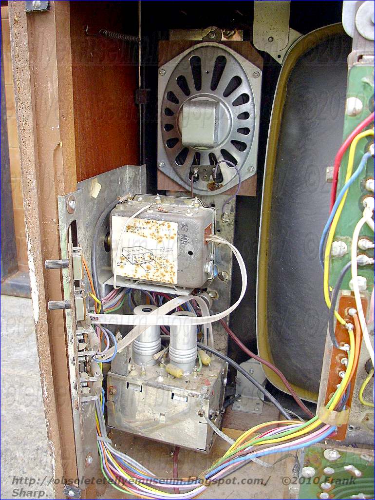
The B/W Tubes Television set was powered with a External Voltage stabiliser unit (portable metal box) which relates to voltage regulators of the type employed to supply alternating current and a constant voltage to a load circuit from a source in which the line voltage varies. Conventional AC-operated television receivers exhibit several undesirable performance attributes. For example, under low-line voltage conditions such as those encountered during peak load periods or temporary power brown-outs imposed during times of power shortage, picture shrinkage and defocusing are encountered and under extreme brown-out conditions the receiver loses synchronization with a resultant total loss of picture intelligibility.

On the other hand, abnormally high-line voltage conditions are sometimes encountered, and this can lead to excessive high voltage and X-ray generation. In addition, either abnormally high steady state line voltage conditions or high voltage transients such as those encountered during electrical storms or during power line switching operations may subject the active devices and other components of the receiver to over-voltage stresses which can lead to excessive component failure.

It is a principal object of the present invention to provide a new and improved AC-operated television receiver having greatly improved performance characteristics in the presence of fluctuating power supply voltages.

A more specific object of the invention is to provide an AC-operated television receiver affording substantially undegraded performance under even extremely low-line voltage conditions without excessive high voltage and X-ray generation under even extremely high-line voltage conditions.

Still another and extremely important object of the invention is to provide a new and improved AC-operated television receiver having greatly improved reliability against component failure. Such regulators are frequently provided employing saturable core reactors and condensers connected in circuit...  in such manner as to provide a plurality of variable voltage vectors which vary in different senses, as the line voltage varies, but which add vectorially in such manner that their vector sum remains substantially constant upon variations in line voltage, for providing automatic voltage stabilization of single or multiphase A. C. circuits where the supply voltage and frequency are subject to variation above and below normal value and where the load is subject to variation between normal limits

The voltage stabilization is automatically effected by the provision of an inductive pilot control device which is adapted to provide two excitation supply voltages for producing excitation or saturation of two magnetic circuits of a reversible booster transformer unit or units and diversion of flux from one magnetic circuit to the other, the booster unit being energized by primary windings from the A. C. supplysystem and being provided with a secondary winding or windings connected between the supply system and the corresponding inain or distribution circuit and in series therewith, through which a corrective boost voltage is
introduced into the circuit under the
influence of the pilot control device, of an amount equal to that of the supply voltage fluctuation which initiated it and appropriate in polarity and direction for restoring the voltage to normal value and providing automatic stabilization of the circuit voltage against supply voltages which fluctuate above and below normal value.


The pilot control device which may be employed singly or may comprise three units or their equivalent when applied to multiphase supply systems comprises a pair of closed magnetic circuits or cores constructed of strip wound magnetic material or stacked laminations, the two
circuits forming a pair being constructed of materials possessing dis~similar magnetic characteristics when jointly energized by identical windings in series or by a collective primary winding, the said magnetic circuits being suitably proportioned to provide equal fluxes when energized at normal voltage.

The pilot control device is
the auxiliary secondary winding embraces only one circuit, preferably that subject to the least amount of flux variation. Either of the windings consists of two equal sections or in effect a double winding with a center tapping to which one end of the single winding is connected.
provided with a main and an auxiliary secondary winding or group of windings, the main secondary winding or windings being adapted to provide a voltage representing the difference in the fluxes of the two circuits to which it is jointly associated, while

The voltage in the single secondary winding of the pilot device becomes directionally additive to that in one half of the tapped secondary winding and substractive in respect to that in the other half. When the supply voltage is normal the voltage provided by the single secondary winding is zero, since there is no difference of flux in the two magnetic circuits, and the two excitation voltages
produced in the halves of the other secondary winding are equal and when connected to the two excitation windings of the booster units, do not produce 
any diversion of flux between the two circuits or sets of circuits in the magnetic system of the booster transformer unit become equal, and since the series winding on the booster unit is arranged to provide a voltage due to the difference of
the fluxes in its two magnetic circuits or sets of magnetic circuits, no corrective voltage is introduced into the main circuit by the booster. If, however, the supply voltage varies from normal the pilot control device provides a voltage across the one secondary winding due to the difference in the fluxes of the two dis-similar magnetic circuits of which it is comprised, which voltage is combined with thosc in the halves of the other secondary winding to provide two excitation voltages which vary complementarily to each other as the supply voltage fluotuates, and cause a transference of flux between the two
circuits or groups of circuits in the booster unit and automatically provide a corrective boost voltage in the main circuit in which the series winding of the booster transformer is includcd of a value equal to that of the variation in supply voltage which initiated it.
The pilot device may be arranged in various ways, forboth single phase and multiphase operation, as exemplified by the constructions hereinafter more fully described.Similarly, numerous arrangements of the booster transformer unit are possible, some of which are hereinafter described in detail. The booster transformer unit embodies thc principles of the inductive devices described in my co-pending Application No. 411,189, filed February 18, 1954.

As an alternative to the provision of an auxiliary secondary winding on the pilot control device this may be
replaced by an independent or external source of supply,which may be either subject to or independent of supply voltage variation, provided such supply may be arranged with a center tapping if required.

Feed-back arrangements may be employed for providing compensation against voltage drop due to the effects of load in various ways. These are preferably providedon the booster transformer unit and may comprise a current transformer in one or more lines of the main circuit,
the secondary output of the transformer being rectified and arranged to energize an additional excitation winding on the booster transformer unit which in clfect increases the amount of the corrective boost voltage as the load increases.


See here below SINUDYNE History.

SINUDYNE was an Italian manufacturer of radio and television sets.

It was founded in 1946 SEI-Società Elettronica Italiana S.p.A., by two mates : Antonio Longhi and Bruno Berti, and they started manufacturing radio apparates with tubes.

In 1954 the started producing television sets which was in the 70's theyr primary activity.

In 1959 the production was transferred at Ozzano dell'Emilia near Bologna.

SINUDYNE have had a good success in Italy were it have had large diffusion and lots of service centers because a good quality of product and design.

In 1983 SINUDYNE realized the first Italian Digital Television employing the ITT DIGIVISION Technology


SINUDYNE was in the 1980's and in the 1990's even importer of brands like NORDMENDE and
ORION.

SINUDYNE was even known for it's product design which was quite remarcable some times.

The slogan of SINUDYNE in the 80's was "SINUDYNE COLORE STUPORE ! " and it was meaning " SINUDYNE COLOR ASTONISHMENT " in English.

In 2002 SINUDYNE was aquired by another Italian group called Merloni which introduced productions of appliances like air conditioning clima systems.

In 2003 SINUDYNE started marketing LCD (Crap) displays.

In 2006 SINUDYNE closed his production factory landing to fail !!


TODAY'S SINUDYNE IS NO MORE.


A good point  on good  old  B/W Televisions.....................

The Sixties was a time of great change for TV. At the start of the decade there were just monochrome sets with valves, designed for 405 -line transmissions at VHF. By the end there was 625 -line colour at UHF, with transistorised chassis that used the odd IC.

The following decade was one of growth. The "space race" had begun in 1957, when the USSR launched Sputnik 1 and terrified the Americans. Thereafter the USA began to spend countless billions of dollars on space missions. This got underway in earnest in the Sixties, with the announcement that America would be going all out to get a man on the moon by the end of the decade. There followed the Mercury series of earth - orbit missions, then the Apollo launches. Success was achieved in 1969. Most of these missions were televised, and in those days anything to do with space was hot stuff. It was inevitable that everyone wanted to have a television set. At the time an average receiver would be a monochrome one with a 14in. tube - there was no colour until 1967. It would cost about 75 guineas. 
TV sets were often priced in guineas (21 shillings) as it made the price look a bit easier on the pocket. Anyway 75 guineas, equivalent to about £78.75 in 2000's currency, was a lot of money then.  For those who couldn't, rental was a good option. The Sixties was a period of tremendous growth for rental TV. 
Much else was rented at that time, even radios, also washing machines, spin driers, refrigerators and, later on, audio tape recorders (no VCRs then). 
For most people these things were too expensive for cash purchase. 
There were no credit cards then. And when it came to a TV set, the question of reli- ability had to be taken into account: renting took care of repair costs. 

TV reliability.........The TV sets of the period were notoriously unreliable. They still used valves, which meant that a large amount of heat was generated. The dropper resistor contributed to this: it was used mainly as a series device to reduce the mains voltage to the level required to power the valve heaters. These were generally connected in series, so the heater volt- ages of all the valves were added together and the total was subtracted from the mains voltage. The difference was the voltage across the heater section of the dropper resistor, whose value was determined by simple application of Ohm's Law. 
As valves are voltage -operated devices, there was no need to stabilise the current. So the power supply circuits in TV sets were very simple. They often consisted of nothing more than a dropper resistor, a half or biphase rectifier and a couple of smoothing capacitors. If a TV set had a transformer and a full wave rectifier in addition to the other components, it was sophisticated!
 As the valve heaters were connected in series they were like Christmas -tree lights: should one fail they all went out and the TV set ceased to function. Another common problem with valves is the cathode -to -heater short. When this fault occurs in a valve, some of the heaters in the chain would go out and some would stay on. Those that stayed on would glow like search- lights, often becoming damaged as a result. Dropper failure could cause loss of HT (dead set with the heaters glowing), or no heater supply with HT present. When the HT rectifier valve went low emission, there was low EHT, a small picture and poor performance all round. CRTs would go soft or low emission, the result being a faint picture, or cathode -to -heater short-circuit, the result this time being uncontrollable brightness. On average a TV set would have twelve to fourteen valves, any one of which could go low -emission or fail in some other way. All valves have a finite life, so each one would probably have to be replaced at one time or another. The amount of heat generated in an average TV set would dry out the capacitors, which then failed. So you can see why people rented! 

The CRT could cause various problems. Because of its cost, it was the gen- eral practice to place its heater at the earthy end of the chain. In this position it was less likely to be overloaded by a heater chain fault. But during the winter months, when the mains voltage dropped a bit, it would be starved of power. This would eventually lead to 'cathode poi- soning' with loss of emission. The 'cure' for this was to fit a booster transformer designed to overrun the heater by 10, 20 or 30 per cent. It would work fine for a while, until the CRT completely expired. At about this time CRT reactivators came into being - and a weird and wonderful collection of devices they turned out to be. Regunned tubes also started to appear. You couldn't do this with the `hard -glass' triode tubes made by Emitron. These were fitted in a number of older sets. Yes, they were still around, at least during the early Sixties.


Developments................... A great deal of development occurred during the Sixties. Many TV sets and radios made in the early Sixties were still hard -wired: the introduction of the printed circuit board changed the construction of electronic equipment forever. The first one was in a Pam transistor radio. PCBs were ideal for use in transistor radios, because of the small size of the components used and the fact that such radios ran almost cold. 
They were not so good for use with valve circuitry, as the heat from the valves caused all sorts of problems. Print cracks could develop if a board became warped. If it became carbonised there could be serious leakage and tracking problems. In addition it was more difficult to remove components from a PCB. Many technicians at that time didn't like PCBs. As the Sixties progressed, transistors took over more and more in TV sets. They first appeared in a rather random fashion, for example in the sync separator stages in some Pye models. Then the IF strip became transistorised. Early transistors were based on the use of germanium, which was far from ideal. 

The change to silicon produced devices that were more robust and had a better signal-to-noise ratio. 
Car radios became fully transistorised, and 'solid-state' circuitry ceased to be based on earlier valve arrangements. Many hi-fi amplifiers had been transistorised from the late Fifties, and all tape recorders were now solid-state. 
Both reel-to-reel and compact -cassette recorders were available at this time. Initially, audio cassette recorders had a maximum upper frequency response of only about 9kHz. 
To increase it meant either a smaller head gap or a faster speed. Philips, which developed the compact audio cassette and holds the patents for the design (which we still use in 2000!) wouldn't allow an increase in speed. Good reel-to-reel recorders had a fre- quency response that extended to 20kHz when the tape speed was 15in./sec. 
This is true hi-fi. In time the frequency response of compact -cassette recorders did improve, because of the use of better head materials with a smaller gap. 
This led to the demise of the reel-to-reel audio recorder as a domestic product We began to benefit from spin-offs of the space race between the USA and the USSR. 
The need to squeeze as much technology as possible into the early computers in the Mercury space capsules used by the USA lead to the first inte- grated circuits. 
This technology soon found its way into consumer equipment. Often these devices were hybrid encap- sulations rather than true chips, but they did improve reliability and saved space. The few chips around in those days were analogue devices.  To start with most UHF tuners used valves such as the PC86 and PC88. They were all manually tuned. Some had slow-motion drives and others had push -buttons. They didn't have a lot of gain, so it was important to have an adequate aerial and use low -loss cable..............................


Further readings and more Notes:


^ (IT) Duesse Communication S.r.l., Sinudyne: delocalizzata in Lituania la produzione di Crt e Lcd, in E2S. URL consultato il 22 agosto 2018.
 
 
Redazione, la crisi, in La Repubblica - Sezione di Bologna, 1º settembre 2006, p. 2. URL consultato il 20 febbraio 2021.

Chi siamo 1946-1970, su sinudyne.com. URL consultato il 20 febbraio 2021 (archiviato dall'url originale il 5 maggio 2006).

Bruno Berti, su virtuspedia.it. URL consultato il 20 febbraio 2021.
^ 1950, su sinudyne.com. URL consultato il 20 febbraio 2021 (archiviato dall'url originale il 5 maggio 2006).
^ 1953, su sinudyne.com. URL consultato il 20 febbraio 2021 (archiviato dall'url originale il 5 maggio 2006).

Quale futuro per la tv Made in Italy?, in Trade Consumer Electronics, E2S, settembre 2006, p. 34.
^ 1954, su sinudyne.com. URL consultato il 20 febbraio 2021 (archiviato dall'url originale il 5 maggio 2006).
^ 1956, su sinudyne.com. URL consultato il 20 febbraio 2021 (archiviato dall'url originale il 5 maggio 2006).

R. Ferretti, L'industrializzazione: dalla comunità locale ai mercati mondiali, in Dalla guerra al "boom". Territorio, economia, società e politica nei comuni della pianura orientale bolognese. Industrializzazione e società. Economia, demografia e stili di vita, vol. 3, 2006, p. 177.
^ 1964, su sinudyne.com. URL consultato il 21 febbraio 2021 (archiviato dall'url originale il 5 maggio 2006).
^ 1969, su sinudyne.com. URL consultato il 21 febbraio 2021 (archiviato dall'url originale il 5 maggio 2006).
^ 1970, su sinudyne.com. URL consultato il 21 febbraio 2021 (archiviato dall'url originale il 5 maggio 2006).
^ 1975, su sinudyne.com. URL consultato il 21 febbraio 2021 (archiviato dall'url originale il 5 maggio 2006).
^ 1980, su sinudyne.com. URL consultato il 21 febbraio 2021 (archiviato dall'url originale il 5 maggio 2006).
^ R. Cominotti, S. Mariotti, Italia multinazionale 1990. L'integrazione internazionale e le prospettive del Mercato Unico Europeo. III rapporto R&P al CNEL, Franco Angeli, 1990, pp. 304, 421.
^ Sinudyne, Societá Elettronica Italiana, su radiomuseum.org. URL consultato il 6 luglio 2022 (archiviato il 1º luglio 2018).
^ 1983, su sinudyne.com. URL consultato il 21 febbraio 2021 (archiviato dall'url originale il 5 maggio 2006).
^ Redazione, S.E.I. Sinudyne: il marchio Orion sarà distribuito da Euronics, in E-Duesse.it, 1º maggio 2009. URL consultato il 6 luglio 2022 (archiviato il 6 luglio 2022).
^ 1992, su sinudyne.com. URL consultato il 21 febbraio 2021 (archiviato dall'url originale il 5 maggio 2006).
^ 1993-2002, su sinudyne.com. URL consultato il 21 febbraio 2021 (archiviato dall'url originale il 5 maggio 2006).
^ 1996, su sinudyne.com. URL consultato il 21 febbraio 2021 (archiviato dall'url originale il 5 maggio 2006).
^ 1997, su sinudyne.com. URL consultato il 21 febbraio 2021 (archiviato dall'url originale il 5 maggio 2006).
^ 1998, su sinudyne.com. URL consultato il 21 febbraio 2021 (archiviato dall'url originale il 5 maggio 2006).
^ 1999, su sinudyne.com. URL consultato il 21 febbraio 2021 (archiviato dall'url originale il 5 maggio 2006).
^ (ES) Audiotecnic, televisores para todo el mundo, in Laesfera, 21 dicembre 2003. URL consultato il 21 febbraio 2021 (archiviato dall'url originale il 27 dicembre 2009).
^ (ES) La plantilla de Audiotecnic (antigua Thomson) se concentra en San Sebastián de los Reyes (Madrid), en defensa de sus empleos, in ANIA, 16 novembre 2004. URL consultato il 21 febbraio 2021.
^ 2000, su sinudyne.com. URL consultato il 21 febbraio 2021 (archiviato dall'url originale il 5 maggio 2006).
^ Redazione, Sinudyne: l'azienda acquisita da Panini, in E-Duesse.it, 1º maggio 2009. URL consultato il 6 luglio 2022 (archiviato il 6 luglio 2022).
^ Redazione, EICMA: BERTI, MOTO MORINI SI RISVEGLIA, in Motor Press, 17 novembre 2005. URL consultato il 6 luglio 2022 (archiviato il 28 luglio 2021).
^ L. Nigro, Rinasce un marchio storico torna la Moto Morini, in La Repubblica - Sezione di Bologna, 5 dicembre 2003, p. 5. URL consultato il 6 luglio 2022 (archiviato l'11 agosto 2018).
^ Synudine vuole licenziare 83 dipendenti, in L'Unità, 25 giugno 2005, p. 14.
^ Fineldo, lo scrigno di famiglia che ha fatto il peno di utili, in La Repubblica, 12 novembre 2007, p. 19. URL consultato il 6 luglio 2022 (archiviato l'8 marzo 2013).
^ Redazione, SINUDYNE: L'AZIENDA ACQUISITA DA PANINI, in E-Duesse.it, 9 aprile 2003. URL consultato il 21 febbraio 2021.
^ Storia 2003, su sinudyne.com. URL consultato il 21 febbraio 2021 (archiviato dall'url originale il 5 maggio 2006).
^ Duesse Communication S.r.l., Sinudyne: in arrivo il televisore con combinato Dvd+Vhs, in E2S, 19 novembre 2002. URL consultato il 6 luglio 2022 (archiviato il 6 luglio 2022).
^ Lamberto Angelini, in Ottagono, n. 174, Editrice Co.P.IN.A, ottobre 2004, p. 174.
^ Product, su angelinidesign.eu. URL consultato il 21 febbraio 2021.
^ Redazione, Merloni Progetti: nasce la linea ped a marchio Sinudyne, in E-Duesse.it, 1º maggio 2009. URL consultato il 6 luglio 2022 (archiviato il 6 luglio 2022).
^ Redazione, Sinudyne: delocalizzata in Lituania la produzione di Crt e Lcd, in E-Duesse.it, 1º maggio 2009. URL consultato il 6 luglio 2022 (archiviato il 6 luglio 2022).
^ F. Allegra, Merloni e Mister Panini cercano un socio cinese per i televisori Sinudyne, in Milano Finanza, n. 181, 14 settembre 2005, p. 10.
^ Redazione, MERLONI PROGETTI: JOINT VENTURE CON JOYCARE, in E-Duesse.it, 21 febbraio 2006. URL consultato il 21 febbraio 2021.

Redazione, Sinudyne: l'azienda chiude, in E-Duesse.it, 1º maggio 2009. URL consultato il 6 luglio 2022 (archiviato il 6 luglio 2022). ^ Sinudyne: l'azienda chiude. Accordo per mobilità lavoratori, in Sassuolo 2000. URL consultato il 6 luglio 2022 (archiviato dall'url originale il 23 settembre 2020). ^ Capannoni ex Sinudyne di Ozzano demoliti entro 2 mesi | Sabato Sera, su sabatosera.it, 2 marzo 2021. URL consultato il 6 luglio 2022 (archiviato il 6 luglio 2022). ^ Iniziati i lavori di abbattimento dei capannoni dell'ex Sinudyne. | Comune di Ozzano dell'Emilia, su comune.ozzano.bo.it. URL consultato il 6 luglio 2022 (archiviato il 19 giugno 2022). ^ Ditte anni 60, su carlobramantiradio.it. URL consultato il 6 luglio 2022 (archiviato il 6 luglio 2022). ^ Sinudyne, su virtuspedia.it. URL consultato il 6 luglio 2022 (archiviato il 25 aprile 2022). ^ La Virtus Sinudyne vince il campionato di basket, 4 aprile 1976, su bibliotecasalaborsa.it. URL consultato il 13 gennaio 2023. ^ M. Bertuzzi, F. Monti, La maglia del Bologna. Storia delle divise rossoblù, Edizioni Minerva, 2017, pp. 156-159.

6 SINUDYNE MOD. 2470 CHASSIS INTERNAL VIEW.


The chassis is completely based on tubes technology and it's divided in 2 main sections:

- Above PCB Deflection power circuits.

- Bottom PCB Signal circuits.


NOTE: The chassis has some PCB's with cracks developed by unfair vandalism,
 People are BAD believe me !


Tuning is obtained with rotatable drum selectors for VHF and variable rotatable capacitor for UHF.
A rotatable drum containing twelve pre-defined channel-specific filters determines the received channel, where the inductors of the input matching, the channel filter and the LO tank circuit are changed. The tuner is divided into two chambers for maximum isolation between the sensitive RF input and the mixer-oscillator-IF section with its much larger signals. Also on the drum there are eventually two separate sub-modules.
It's completely based on tubes technology.
With this concept, which essentially turned the tuner module into a kind of Lego building block construction, many different tuners became possible. Depending upon the country of destination and its associated standard and IF settings, the required filter modules would be selected. Service workshops and tv fabricants could later even add or exchange modules when new channels were introduced, since every inductor module had its individual factory code and could be ordered separately. As a consequence more versions of the tuner were produced, covering at least standards B, B-for-Italy, C. E, F and M.


The principle of the drum tuner. On an axis two times 12 regularly spaced channel-specific filter modules are mounted. In front are twelve channel filter modules for both the channel filter and LO tank circuit tuning. Seven contacts are available, and one module is shown removed. The second row contains 12 modules with five contacts for the input filter circuit. In the tuner module the front section (for mixer-ocillator and channel filter) is separated by a metal shield from the rear RF input and pre-amp section. [Philips Service "Documentatie voor de kanalenkiezers met spoelenwals", 1954]
Examples of the filter modules as used in the drum tuner. Left the 5-contact input filter, right the 7-contact BPF and LO tank filters. In both modules the coils are co-axial for (maximum) mutual coupling.


The second new valve introduced in the tuners family was the PCF80, a triode-pentode combo valve specifically designed for the VHF mixer-oscillator role. First order the circuit principles didn't change too much from the previous ECC81 based generation, with the triode acting as a Colpitts oscillator with a tuned feedback from anode to grid. The oscillator voltage was minimally 5V at the grid, and would be inductively coupled to the input of the mixer pentode. This inductive coupling was achieved by putting the oscillator coil S7 and the BPF coils S5 and S6 on the same rod inside the drum tuner filter modules, see Fig.5 above. By adjusting the distance between these coils for each channel filter module, the coupling constant could be kept more or less constant across all channels, providing as much as possible a frequency-independent mixer performance. For the mixer the pentode replaced the previous triode, providing more feedback isolation between anode and grid. All in all the new tuner must have given a considerable performance improvement compared to the previous generation.

Constant potential transformer / Constant Voltage transformer :

 The old B/W Tubes Television set was powered with a External Voltage stabiliser / Constant Voltage transformer unit (portable metal box) because  There was intermittent significant rapid line voltage dips here and there that were rather annoying when watching a tube set with an unregulated power supply (like all tvs of ancient times) and it eliminates the line dip issue completely.


(The, of mine, Pictured Constant Voltage transformer unit taken as example is a "KURTIS" STV/3 Italian Manufactured in Milan (Italy) in Year 1954 with a 250 VA power displacement and developed under Italian Patent 50499. It's clearly reported that input may be universal within -20%  +10% variations, output is precisely regulated within 1% range.........................click on pictures to enlarge them at full screen......)

The invention relates to voltage regulators of the type employed to supply alternating current and a constant voltage to a load circuit from a source in which the line voltage varies. They are particularly advantageous in connection with commercial applications such as amplifiers for talking motion pictures, amplifiers for radio transmitters,  Television sets (tubes),   mercury arc lamps, X-ray apparatus, etc.


Features : Instantaneous Voltage regulation. No effect of input Transient and spikes on the output. Sinusoidal output waveform. Was a  perfect answer and remedy for all types of electronic equipment. The  CVT have been designed to give you total protection against power related problems and to condition the power to suit the needs of Tubes television sets based equipment. It effectively regulates voltage variation, suppresses transients and bridges short interruptions/dips.

Basics: Ferro Resonant type Constant Voltage Transformers - CVT, the AC mains power the input winding, which The input winding normally runs at very moderate Flux linkage levels. The output winding exhibits an intrinsic energy characteristic and this energy storage operate in conjunction with mains capacitor to produce self-generated AC flux Field which is indirectly extracted from the Input Winding.
These Constant Voltage transformer or CVT use a tank circuit composed of a high-voltage resonant winding and a capacitor to produce a nearly constant average output with a varying input. The ferroresonant approach is attractive due to its lack of active components, relying on the square loop saturation characteristics of the tank circuit to absorb variations in average input voltage.

The ferroresonant action is a flux limiter rather than a voltage regulator, but with a fixed supply frequency it can maintain an almost constant average output voltage even as the input voltage varies widely.

All problems related to variation / fluctuation in Voltages are effectively handled because of this principle and a constant voltage output of ± 1% is given.


 INVENTOR: JOSEPH G. SOLA.

The  invention relates to an improved constant potential transformer by means of which variations of input voltage over a wide range of limits may take place without affecting the output voltage to any substantial extent.

One of the objects of my invention is to provide a constant potential transformer which is compact as a unit and which may be economically manufactured.

o1 It is another object of my invention to provide a transformer of this type in which the efficiency and input power factor are high while the temperature rise of the magnetic core is low.

A further object of my invention is to provide 1., a transformer, the outputvoltage wave of which will have very little distortion and the device will be satisfactory for various commercial applications.

The invention consists of the novel constructions, arrangments and devices to be hereinafter described and claimed for carrying out the above stated objects and such other objects as will appear from the following description of certain preferred embodiments illustrated in the accompanying drawings, wherein,Fig. 1 is a sectional view of one form of construction that may be used; Fig. 2 is a diagrammatic illustration of the wiring arrangement that may be used in connection with a construction such as that shown in Fig. 1; Fig. 3 is a sectional view of another form of construction embodying the principles of my invention; Fig. 4 is a diagrammatic illustration of the wiring arrangement that may be used in connection with a construction such as that shown in Fig. 3; Fig. 5 is a diagram showing the vector relations between the various voltages obtained in the illustrated constructions at different values of input voltage; and Fig. 6 is a graph showing the relation between the magnitudes of various voltages obtained in the illustrated constructions as the input voltage is varied.

Like characters of reference designate like parts in the several views.

Referring to Figs. 1 and 2,
it will be seen that a core type of transformer construction is illustrated, the closed magnetic circuit 10 of which comprises a stack of I-shaped laminations II in abutting relation with the end legs 12a of a stack of E-shaped laminations 12, which may be held 5 together by any suitable means. On the end portion A of the core bar 11, I have provided a primary winding 13, the terminals 14 and 15 of which are adapted to be connected with a source of alternating current, the voltage of which from time to time may fluctuate or vary substantially. g On the end portion B of the core bar 11, I have mounted a winding 16, which is in spaced relation to but magnetically coupled with the winding 13, the winding 16 having terminal leads 17 and 18 and an intermediate tap 19. That part of the winding 16 between the lead I7 and tap 19 may be considered as an output or load winding, and the entire winding 16 between the leads 17 and 18 may be termed an intermediate winding.

The magnetic core 10 is provided with a high leakage reactance path between the windings 13 and 16 which in the form shown comprises the central leg 12b of the E-shaped laminations and which terminates short of the core bar 1 thereby providing a non-magnetic or air gap 20 between said leg 12b and the core bar II. In this arrangement, a condenser 21 is connected by leads 22 across the terminals 17 and 18 of the winding 16.

The lead 17 forms one side and the tap 19 the other side of what may be termed an output or load circuit. In the arrangement shown, an auxiliary winding 23 is positioned over the winding 13 and is magnetically coupled therewith, the terminals 24 of said winding 23 being connected in series in the lead 19 of said output circuit. In Figs. 3 and 4, I have illustrated my invention in connection with a well-known shell type of transformer having two closed magnetic circuits 10 and 10a comprising a straight central core bar 25 of I-shaped laminations, the sides of which are in abutting contact with the end legs 26a of the E-shaped laminations 26 and the end legs 27a of the E-shaped laminations 27, said parts being held in operative relation by any suitable means. On the end portion A, of the core bar 25, I have mounted a primary winding 28 the terminals 29 and 30 of which are adapted to be connected to a source of alternating current, the voltage of which may fluctuate substantially from time to time. Another winding 31 is positioned on the end portion B of the core bar 25, the winding 31 being in spaced relation to but magnetically coupled loosely with the winding 28.

A condenser 32 is connected across the terminals 33 and 34 of the winding 31. Another winding 80 35 is mounted on the end portion B of the core bar 25, in the arrangement shown the winding 35 being positioned over and magnetically coupled tightly with the winding 31. The terminal 36 of the winding 35 leads to one side of what may i be termed an output circuit. An auxiliary winding 37 is positioned on the end portion A of the core bar 25 and in the arrangement illustrated the winding 3I is positioned over and magnetically coupled tightly with the winding 28.


A lead 38 connects the winding.37 in series with the winding 35, the lead 39 of the winding 37 forming the other side of the aforesaid output circuit. The winding 35 may be termed an output or load winding and the winding 31 may be considered as an intermediate winding. The closed magnetic circuits described are each provided with a high leakage reactance path between the windings 28 and 37 on the end portion A of the core bar 25 and the windings 31 and 35 on the end portion B of said core bar, which in the arrangement shown comprise the central legs 40 and 41 of the respective E laminations 26 and 27. The shunts 40 and 41 terminate short of the adjacent sides of the core bar 25 thereby providing non-magnetic or air gaps 42 and 43 between the legs 40 and 41 and the core bar 25.

In Figs. 2, 4, 5 and 6 Vo represents the voltage across the output circuit, Vp shows the input voltage on the primary winding, Vs indicates the voltage derived from the winding 16 between the lead 17 and tap IS, and from the winding 35 forming parts of the respective output circuits, and Vpa is the component of the output voltage taken across the terminals of the auxiliary winding 23 or 31, as the case may be.

In Fig. 5, I have shown the vector relations of the various voltages in either arrangement at a certain power output and at different values of primary voltage. The various voltages are either not primed or are primed to correspond to the different values of Vp which is varied. As shown, Vpa is nearly 180* out of phase with Vs, and hence the vectorial sum Vo of the two is approximately their numerical difference.

In Fig. 6, I have illustrated graphically the relation in the constructions described between Vs, Vo, Vpa and Vp ata certain power output.

The principles upon which my improved transformer constructions operate will be clear from a detailed consideration of the construction shown in Figs. 3 and 4. The flux set up by applying a potential across the primary winding 28 will link with winding 31 and cause a definite reactance to be set up by that winding. As the voltage on the. primary winding is increased from zero to a higher level, the flux threading through winding 31 tends to increase in nearly direct proportion to the primary flux, due to the re5 luctance caused by the air gaps 42 and 43, a very slight amount leaking through the shunts 40 and 41. As the Induced E. M. F. reaches a higher value in winding 31 a critical point is reached where resonance takes place, since the reactance of the effective inductance of the winding 31 and the capacity reactance of the condenser 32 are approximately equal at the frequency of the voltage impressed on the winding 28. that is to say.

WCfL where f is the frequency of the voltage impressed on the primary winding 28, L is the effective 70 Inductance of the winding 31, and C is the capacity of the condenser 32. Under this resonant condition, a definite amount of current will flow in the resonant circuit, comprising the winding 31, condenser 32 and leads 33 and 34, and such t6 current will be limited by the constants of that circuit, with the result that a potential will be set up across the winding 31 and a corresponding amount of magnetic flux will be set up in the end portion B of the core bar 25.

It is well known that the inherent characteristic of a resonant ci
rcuit is such that its power vector may be many times greater than that of the generator which supplies the energy to the resonant circuit; in this case the energy is supplied by the primary of the transformer to the resonant circuit comprising winding 31 and condenser 32. By varying the primary voltage across winding 28 so that the magnetic density of section A thereof will still remain under the maximum magnetic density of section B of the core, with which the resonant circuit is associated, the change of flux density in section A of the core due to line variation in the primary will have no appreciable effect on the resonant circuit as the reluctance of the leakage path will be under that of section B of the core and flux will leak through the leakage path between the primary and resonant core portions, which leakage path comprises the shunts 40 and 41 and their respective nonmagnetic gap portions 42 and 43. It is due to this leakage reactance path also that the co-efficient of coupling between the primary winding 28 and the aforesaid resonant circuit is reduced to a certain optimum value, thereby maintaining a balanced condition so that the resonant circuit will continue to oscillate with the maximum current therein at a frequency equal to the frequency impressed on the primary winding. Under this state of resonance, winding 31 will set up a magnetic field in the core portion B which will remain practically constant so long as the density in the magnetic field of the core portion A remains at a lower density than that of the core portion B. It follows that this substantially constant field strength in core portion B will produce also a substantially constant voltage across the terminals of winding 31 and condenser 32, and this voltage will remain at practically a constant level regardless of variation of voltage applied to the primary winding 28. The aforesaid resonant circuit, therefore, becomes a constant primary source of voltage for any winding such as the winding 35 that is directly coupled to the winding 31. This coupling can be effected in any desired way, for example, by means of an auto-type transformer arrangement as shown in Fig. 2, or by mounting the winding 35 over the winding 31 as shown in Fig.

4. In the Fig. 4 construction, the output voltage of the windings 35 will also have a practically 5, constant level voltage independent of the voltage variation in the primary winding 28 so long as the circuit which includes the winding 31 remains in resonance.


The auxiliary regulating winding 37 is coupled go to the portion A of the core and is used to change the percentage of regulation of Vo across the terminals 36 and 39 of the output circuit with a variation of Vp. Since this auxiliary winding 37 on core portion A is directly coupled to the pri- 05 mary winding 28, the voltage induced will always be proportional to the turns ratio of primary winding 28 and the auxiliary winding 37.

A very constant level of voltage Vo across the terminals 36 and 39 may be obtained by suitably T0 apportioning the number of turns of said auxiliary winding 37 in relation to the number of turns in the winding 35. Any percentage of regulation of output voltage in relation to variations of Vp also may be obtained from terminals Ts 2 t ist. .y 36 and 39,-for example, an increase in the prinrary voltage on winding 28 will produce a decrease in output voltage Vo by properly arranging or apportioning winding 37 in relation to the winding 35.

The relation of voltages described has been upon the assumption that the transformer is on an open output circuit, that is to say, with no load on the terminals 36 and 39. If a load be applied on said terminals, a magnetic flux in the aforesaid resonant circuit will be developed corresponding to the load on said output circuit thereby unbalancing the magnetic flux in section B of the core. This density change in core section B will in turn affect the stable relation of the flux in core sections A and B and also the leakage reactance through the aforesaid shunt paths thereby causing a greater amount of useful flux from core section A to thread through core section B, which compensates for the energy used by the consuming circuit and at the same time maintains the resonant circuit in the desired oscillating condition.

It will be readily understood that in transformers embodying the principles of my invention the primary winding electrically connected to the source serves to induce voltage to the resonan
t circuit which is separated from the primary circuit by a high leakage reactance path, thereby providing a low co-efficient of coupling between the primary and the resonant circuits. The aforesaid resonant circuit may be considered as the primary or main source of controlling energy to the winding 35 and hence'to o3 the output or consuming circuit of the transformer.

My improved constant potential transformers are compact and efficient, and are of a small size relative to their power output as compared with other and more cumbersome and expensive apparatus intended for the same purpose. My improved transformers operate at an inherent high power factor, and the output voltage is very close to a pure sine wave.

My improved transformers may be used for many different purposes. They are particularly advantageous in connection with commercial applications such as amplifiers for talking motion pictures, amplifiers for radio transmitters,  Television sets (tubes),   mercury arc lamps, X-ray apparatus, etc.

I wish it to be understood that my invention is not to be limited to the specific constructions shown and described, except so far as the claims may be so limited, as it will be apparent to those skilled in the art that changes in the constructions and arrangements may be made without departing from the principles of my invention.

I claim:1. In a constant potential transformer, the combination of a magnetic core, a winding on said core adapted to be connected to a source of alternating current of fluctuating voltage, a second winding on said core, said core providing a high leakage reactance path for a portion of the flux to thread through one of the windings to the exclusion of the other winding, and means for maintaining the potential across the second winding substantially constant regardless of fluctuations in the input voltage comprising a resonant circuit including said second winding and a condenser, the resonant circuit operating at a frequency equal to the frequency of the voltage impressed on the first winding.

2. In a constant potential transformer, the 7T combination of a magnetic core, a winding on said core adapted to be connected to a source of alternating current of fluctuating voltage, a second winding on said core in spaced relation to said first winding, said core having magnetically disposed between said windings a magnetically 6 permeable shunt with a non-magnetic gap portion, and means for maintaining the potential across the second winding substantially constant regardless of fluctuations in the input voltage comprising a resonant circuit including said second winding and a condenser, the resonant circuit operating at a frequency equal to the frequency of the voltage impressed on the first winding.

3. In a constant potential transformer, the combination of a closed magnetic circuit comprising first and second core portions, a winding on said first core portion adapted to be connected to a source of alternating current of fluctuating voltage, a second winding on said second core portion, said circuit providing a high leakage reactance path for a portion of the flux to thread through one of the windings to the exclusion of the other winding, and means for maintaining the potential across the second winding substantially constant regardless of fluctuations in the input voltage comprising a resonant circuit including said second winding and a condenser, the resonant circuit operating at a frequency equal to the frequency of the voltage impressed on the first winding, the magnetic density at maximum predetermined input voltage of the first core portion being less than the maximum magnetic density of the second core portion.

4. In a constant potential transformer, the 85 combination of a closed magnetic circuit comprising first and second core portions, a win
ding on said first core portion adapted to be connected to a source of alternating current of fluctuating voltage, a second winding on said second core portion in spaced relation to said first winding, said circuit having magnetically disposed between said windings a magnetically permeable shunt with a non-magnetic gap portion, and means for maintaining the potential across the second winding substantially constant regardless of fluctuations in the input voltage comprising a resonant circuit including said second winding and a condenser, the resonant circuit operating at a frequency equal to the frequency of the voltage impressed on the first winding, the magnetic density at maximum predetermined input voltage of the first core portion being less than the maximum magnetic density of the second core portion.

5. A constant potential transformer comprising in combination a magnetic core, a primary winding on said core adapted to be connected to a source of alternating current of fluctuating voltage, a load winding on said core adapted to be connected to an output circuit, said core providing a high leakage reactance path for a portion of the flux to thread through one of the windings to the exclusion of the other winding, and means for maintaining the potential across the load winding substantially constant regard- 05 less of fluctuations in the input voltage comprising a resonant circuit including a condenser and a third winding, the resonant circuit operating at a frequency equal to the frequency of the voltage impressed on the primary winding, the third winding being in inductive relation to the load winding.

6. A constant potential transformer
comprising in combination a magnetic core, a primary winding on said core adapted to be connected to a source of alternating current of fluctuating voltage, a load winding on said core in spaced relation to said primary winding and adapted to be connected to an input circuit, said core having magnetically disposed between said winlings a magnetically permeable shunt with a non-magnetic gap portion.; and means for maintaining the potential across the load winding substantially constant regardless of fluctuations in the input voltage comprising a resonant circuit including a condenser and a third winding, the resonant circuit operating at a frequency equal to the frequency of the voltage impressed on the primary winding, the third winding being in inductive relation to the load winding.

7. A constant potential transformer comprising in combination a closed
magnetic circuit comprising first and second core portions, a primary winding on said first core portion adapted to be Sconnected to a source of alternating current of fluctuating voltage, a load winding on said second core portion and adapted to be connected to an output circuit, said magnetic circuit having magnetically disposed between said windings a magnetically permeable shunt with a non-magnetic gap portion, and means for maintaining the potential across the load winding substantially constant regardless of fluctuations in the input voltage comprising a resonant circuit including a conSdenser and a third winding, the resonant circuit operating at a frequency equal to the frequency of the voltage impressed upon the primary winding, the third winding being on the second core portion and in inductive relation to the load winding, the magnetic density at maximum predetermined input voltage of the first core portion being less than the maximum magnetic density of the second core portion.

8. A constant potential transformer comprising in combination a magnetic core, a primary wind40 ing on said core adapted to be connected to a source of alternating current of fluctuating voltage, a load winding on said core adapted to be connected to an output circuit, said core providing a high leakage reactance path for a portion of the 45 flux to thread through one of the windings to the exclusion of the other winding, a resonant circuit including a condenser and a third winding, the resonant circuit operating at a frequency equal to the frequency of the voltage impressed on the 50 primary winding, the third winding being in inductive relation to the load winding, and an auxiliary winding on the core in inductive relation to the primary winding and in series with the load winding, for the purpose described.

55 9. A constant potential transformer comprising in combination a closed magnetic core comprising first and second core portions, a primary winding on said first core portion adapted to be connected to a source of alternating current of fluctuating 60 voltage, a load winding on said second core portion and adapted to be connected to an output circuit, said core having magnetically disposed between said windings a magnetically permeable shunt with a non-magnetic gap portion, a reso65 nant circuit including a condenser and a third winding, the resonant circuit operating at a frequency equal to the frequency of the voltage impressed on the primary winding, the third winding being in inductive relation to the load winding, and an auxiliary winding on said first core portion in inductive relation to the primary winding and in series with the load winding, the magnetic density at maximum predetermined input voltage of said first core portion being less thain the maximum density of said second core portion.

10. A constant potential transformer comprising in combination a magnetic core, a primary winding on said core adapted to be connected to a source of alternating current of fluctuating voltage, a second winding on said core provided with two leads and an intermediate tap, one of said leads and said tap leading to an output circuit, said core providing a high leakage reactance path for a portion of the flux to thread through one of the windings to the exclusion of the other winding, and means for maintaining in said output circuit a substantially constant potential regardless of fluctuations in the input voltage cornprising a resonant circuit including a condenser connected in series between the leads of said second winding, the resonant circuit operating at a frequency equal to the frequency of the voltage impressed on the primary winding.

11. A constant potential transformer comprising in combination a magnetic core; a primary winding on said core adapted to be connected to a source of alternating current of fluctuating voltage; a second winding on said core provided with two leads and an intermediate tap; said core having magnetically disposed between said windings a magnetically permeable shunt with a non-magnetic gap portion; and means for maintaining in said output circuit a substantially constant potential comprising a resonant circuit ineluding a condenser connected in series between the leads of the second winding, the resonant circuit operating at a frequency equal to the frequency of the voltage impressed on the primary winding, and an auxiliary winding on said core in 40 inductive relation to the primary winding and in series with the load winding.
12. A constant potential transformer comprising in combination a closed magnetic core comprising first and second core portions; a primary 45 winding on said first core portion adapted to be connected to a source of alternating current of fluctuating voltage; a second winding on the second core portion and provided with two leads and an intermediate tap; one of said leadsandsaidtap 50 leading to an output circuit; said core having magnetically disposed between said windings a magnetically permeable shunt with a non-magnetic gap portion; the maximum density at maximum predetermined input voltage of said first 55 core portion being less than the maximum density of said second core portion; and means for maintaining in said output circuit a substantially constant potential comprising a resonant circuit including a condenser connected in series between 60 the leads of the second winding, the resonant circuit operating at a frequency equal to the frequency of the voltage impressed on the primary winding, and an auxiliary winding on said core in inductive relation to the primary winding and o5 in series with the load winding.

JOSEPH G. SOLA.


Transformer having constant and harmonic free output voltage

This invention relates to voltage transforming and regulating apparatus, and to core and coil constructions therefor, more particularly to such apparatus having a substantially harmonic free output voltage, and it is an object of the invention to provide improved apparatus and constructions of the character indicated.

It is a further object of the invention to provide improved apparatus of the character indicated having an output voltage which is substantially constant irrespective of variations of input voltage over a certain range, and which is substantially free of harmonics.

It is a further object of the invention to provide an improved transformer.

To provide a source of alternating current voltage of a desired frequency which is free of harmonics, that is, a sine wave, has long been a problem because of the undesired eifects produced thereby. For example, instruments which receive a voltage having harmonics therein may give erroneous and sometimes erratic indications. Apparatus supplied with a voltage having harmonies therein may overheat, and its useful life may be lessened. If the transformer which is supplying a voltage is responsible for the generation of harmonics, the supply transformer as well as the apparatus connected to it may overheat.

Commercial power systems supplying alternating current voltage approach the desired condition of a harmonic free voltage, and a large amount of technical eifort is devoted thereto. However, even with the extensive attention directed to this problem, it frequently occurs, in industrial areas particularly, that the supply voltage has an undesired percentage of harmonics.

In the Patent No. 2,143,745, Joseph G. Sola, entitled Constant Voltage Transformer, there is disclosed and claimed apparatus including a transformer and a condenser wherein a substantially constant output voltage is obtained throughout a certain range of variation in input voltage. While the output voltage of apparatus constructed according to the said patent has good wave form, that is, one largely free of harmonics, under certain conditions the voltage output has included as much as five per cent of third harmonic.

Filter circuits which are connected between the output of a source and a load and which serve to substantially reduce or eliminate harmonics are known. Such filters generally require the use of additional condensers and inductors and will correct the output voltage only when load current is flowing. Moreover, the correction may depend upon the amount of the load, there being the greatest correction at full load and substantially none at no load.

Accordingly, it is a further object of the invention to provide an improved transformer which will provide a constant output voltage substantially free of harmonics, which does not require additional condensers or inductors, and which will substantially eliminate the harmonics from no load to full load.

It is a further object of the invention to provide an improved transformer of the character indicated which will have improved efficiency in operation and which is economical to manufacture.

In carrying out the invention in one form, a transformer is provided having substantially constant output voltage and a substantially harmonic free output voltage and comprising in combination, a core, a primary winding and a secondary winding on the core, a high reluctance shunt magnetically disposed between the primary 2,694,177 Patented Nov. 9, 1954 and secondary windings, a third winding disposed on the core in a position to link with a portion of the leakage flux of the secondary winding and to be substantially free of any linkage with the leakage flux of the primary winding, a condenser which is connected in circuit with the secondary winding and the third winding, the condenser having a value of capacity such that when the transformer is excited with a voltage of predetermined magnitude and frequency a condition of a series resonant nature exists at that frequency, and means for connecting a load circuit to a certain portion of the secondary winding.

For a more complete understanding of the invention, relilferfince should be had to the accompanying drawings in w to Figure 1 is a sectional view of a transformer core and coils according to one form of the invention, and

Figure 2 is a diagrammatic representation of a system according to the invention and employing the core and coils of Fig. 1.

Referring to Figs. 1 and 2 of the drawing, the invention is shown embodied in regulating apparatus including a core and coil arrangement 10 having input, output, regulating and compensating windings and a condenser 11 connected to certain of these windings, all to be more particularly described.

The core and coil arrangement 10 comprises a core 12 which may be made of laminations stamped in the form shown and made of suitable material such, for example, as 26 gauge transformer C steel. The core, as shown, is composed of laminations or layers, each of which consists of two pieces, and when assembled into a stack of desired thickness form an outer piece or shell 13 and a center leg 14. The outer shell includes a pair of end legs 6 and 7 and a pair of side legs 8 and 9. The laminations of center leg 14 may be stamped from the pieces forming the outer shell 13 as part of the same process during which the openings or coil windows 15, 16, 17, 18, 19 and 21 are also formed. A core of the proper thickness is formed by assembling together the required number of outer shell laminations and pressing into the appropriate space the same number of center leg laminations assembled together, as is well understood in this art.

Each lamination of the outer shell 13, as shown, comprises a complete or continuous piece of metal with no joints therein. It will be understood, however, that the same configuration can be made up of individual pieces if so desired. Projecting inwardly from leg 8 between the coil windows 16 and 17 is a member 22 formed of the corresponding parts of the laminations of shell 13, and projecting inwardly from leg 9 between coil windows and 18 is a member 23 also formed of the corresponding parts of the laminations of shell 13. Projecting inwardly between coil windows 17 and 21 is a member 24 formed of parts of the laminations of shell 13, and projecting inwardly between coil windows 18 and 19 is a member 25 also formed of the corresponding parts of the laminations of shell 13. Projecting outwardly from the center leg 14 are members 26 and 27 formed of corresponding parts of the center leg laminations and so disposed as to lie between the coil windows 15 and 18 and 16 and 17 and to be disposed opposite the members 23 and 22, respectively, when the center leg 14 is disposed in shell 13 with the right end thereof forming the joint 28.

The members 22 and 27 are spaced from each other by a nonmagnetic gap 29, and the members 23 and 26 are spaced from each other by a nonmagnetic gap 31. The members 24 and 25 are formed of such a length as to tightly abut the center leg 14 at the joints 32 and 33 and have a cross-sectional area substantially less than that of the end leg 7 of the outer shell 13. The center .leg 14 is formed of a length so as to tightly abut the outer shell at joint 28 at one end and to leave a nonmagnetic gap 35 between the other end of the center leg and the inside surface of end leg 7.

Coil windows 15 and 16 comprise a space within which a primary winding 36 and a compensating winding 37 are disposed; coil windows 17 and 18 form a space within which a secondary winding 38 is disposed;

and coil windows 19 and 21 comprise a space within which a neutralizing winding 3% is disposed. Each of the coils or windings 36, 3'7, 38 and 39 comprise an appropriate number of turns and are provided with sufficient insulation, as is shown schematically in Fig. 1. Each of the coils may be preformed and placed upon the center leg and the unit pressed into the outer shell so as to form the nonmagnetic gap 35 and the abutting joints 23, 32 and 33.

The members 22 and 27 and gap 29, and members 23 and 26 and gap 31, form a high magnetic leakage path between the primary winding 36 and the secondary winding 38. The width of the members 22, 27, 23 and and the length of the nonmagnetic gaps 23 and 31 are chosen so as to provide the desired amount of magnetic leakage reactance, as will become clear subsequently in this specification. While the members 22 and 2'7 and gap 29, and members 23 and 26 and gap 31, as shown, form a high magnetic leakage pathway, it will be understood that the high magnetic leakage pathway may be formed in other well understood manners.

The members 24 and 25, the end of leg 14 together with the end leg 7 and the nonmagnetic gap 35 complete the end path for magnetic flux generated by the primary winding. Since the joints 32 and 33 are press-fits, there is little magnetic reluctance thereat, and consequently the members 24 and 25 form a return path which carries the major portion of the primary flux. These mom bers, however, are formed narrower than the end leg 7 whereby a small percentage of the primary flux flows through the end leg 7. The nonmagnetic gap 35 produces high reluctance in the path of the primary flux, thereby reducing the amount of flux which would flow through leg 7 if the gap were not there, and increasing the percentage of primary flux which flows through members 24 and 25.

The structure as thus far described in Fig. l is illustrated diagrammatically in Fig. 2, the same reference characters being used in the two figures to designate corresponding parts. Thus the windings 36 and 38 are disposed on a common core with a high leakage reactance shunt 22, 27, 29, 23, 26, and 31 disposed therebetween, winding 39 is disposed on the same magnetic core with the nonmagnetic gap 35 separating the core parts, and winding 3'7 is disposed in a closely coupled relationship to winding 36.

The effect of the high leakage path between primary winding 36 and secondary winding 38 is to relatively loosely couple these windings so that each of the windings has a high leakage reactance, and nonmagnetic gap 35 tends to isolate the winding 39 from the flux of the primary winding.

The primary winding 36 is adapted to be connected to a line or source by conductors 41 and 42. The secondary winding 38 has one of its ends connected by means of a conductor 43 to one terminal of condenser ll, and has its other end connected by means of a conductor 44 to one end of neutralizing winding 39 by a conductor 45. The other end of neutralizing winding 3% is connected by means of a conductor 46 to the other terminal of condenser 11. The conductors 44 and 45 connected together may be connected to one side of a load circuit through a conductor 47, and the other side of the load may be connected through a conductor 48 to one end of a compensating winding 37, the other end of which is connected by means of a conductor 49 to a tap on the secondary winding 38. The load circuit may then be traced as follows: From one side of the load through conductor 47, conductor 44, the right-hand portion of winding 38, conductor 49, winding 37, and conductor 43 to the other side of the load.

The operation of the apparatus may perhaps best be understood by considering its operation in two phases; that is, as a constant voltage apparatus alone, and as the combination of the constant voltage and the harmonic elimination or neutralizing apparatus. Considering first the constant potential aspects of the apparatus, it may be made such in one form by removing, in efiect, the neutralizing winding 39. Referring to Fig. 2, this may be accomplished by connecting conductor 46 to conductors 44 and 47 and disconnecting conductor 45 from conductors 44 and 47. When so connected, the apparatus of Figs. 1 and 2 is essentially similar to the form of the apparatus illustrated in the Patent No. 2,143,745, already hereinbefore referred to. When connected in this form as only a constant potential device,

the members 24 and 25, together with leg 7, form a portion of the return circuit for the primary winding flux and provide a return leg having substantially the same elfgctgive cross section as the other flux return legs 8 an For a complete understanding of the operation of the device in this form as a constant voltage transformer, reference may be had to the aforesaid Patent No. 2,143,745. Briefly, however, when voltage above a certain magnitude is applied to the primary winding 36 through conductors 41 and 42, a condition approximating series resonance is set up in the apparatus, and particularly in the circuit including condenser 11 and winding 38. When this condition exists, a substantially constant voltage is obtained across conductors 4'7 and 49 over a wide range of variations in voltage applied to the primary winding. Such small changes as occur in this voltage may be compensated for by the winding 37 which is closely coupled to winding 36 and which is in such a relation as to buck the voltage existing across conductors 47 and 49. Thus, if the primary voltage rises and the output voltage would tend to rise on account thereof, the compensating winding prevents it. Likewise, if the primary voltage falls and the output voltage tends to fall, the bucking voltage is also reduced and the output voltage remains the same. By proper choice of turns of winding 37, the load voltage, that is, the voltage appearing across conductors 47 and 48, is made substantially constant.

Vvhile explanation of the operation of this form of the device as a constant potential apparatus does not lend itself to simple terms, it is thought that the currents flowing in the condenser 11 and winding 38, due to the existing resonance condition, set up a llux condition in the portion of the core underneath and directly associated with the winding 38, due to the presence of the shunts between the primary and secondary windings 36 and 38, such that changes in flux caused by changes in voltage across the primary winding are largely absorbed in the shunts and thus do not change the flux conditions of the secondary winding. The output voltage or" the device as a constant voltage transformer has good wave shape, but it does have appreciable percentages of harmonies in it which are eliminated by the presence of the neutralizing winding 39. When the device is operating as a constant voltage apparatus and the winding 39 is present in the core but is not connected to the circuit, the winding 39 will, of course, have a voltage induced into it since a certain percentage of flux will course through the center leg 14 and through the end leg 7. With the core constructed as shown and described, it has been found that the voltage of coil 3? has a high percentage of odd harmonics in it, that is, third, fifth, seventh and ninth, etc. There is also present a certain value of fundamental since the winding 39 is linked by a small percentage of the flux set up by the primary winding. The presence of the odd harmonic voltages in winding 39 is due to the linkage of winding 39 by the leakage flux created by winding 38 when current flows through the condenser 11 and winding 33. This leakage flux, of course, has two pathways to follow, one of these including a portion of the central leg 14, the members 24 and 25, a portion of the legs 8 and 9 of the core,

. which links with winding 39, that is, that portion of these windings prior to such connection.

the secondary leakage flux which flows across gap 35 and through leg 7. The leakage flux of the primary winding 36 flows largely through the shunts 22, 27, 29 and 23, 26, 31 and thus does not link with winding 39. Consider now the second phase of the device. The winding 39 is connected in circuit with and in additive polarity to winding 38 and with condenser 11 as shown, to form a constant voltage and harmonic free device. When so connected the combined voltage of windings 38 and 39 is increased over the sum of the voltages of With the con nections so made, the percentage of odd harmonics existing in the winding 38 and across the conductors 47 and 49 is very much reduced and a constant voltage output also is had. They are, in fact, reduced to a virtually negligible amplitude. After. the connection has been made, as shown in Fig. 2, the harmonic voltage still '5 exists across winding 39 and also across the condenser 11, but these harmonic voltages are of such phase that they neutralize the harmonics which formerly existed in the Winding 38. For example the third harmonic, which exists in winding 39, is induced therein by the leakage flux from Winding 38, and this harmonic voltage is approximately 180 out of phase with the third harmonic voltage existing in winding 38.

With winding 39 connected into circuit in additive polarity, there has been, in effect, a number of turns added to the secondary winding, but these turns and the core configuration produce harmonic elimination and do not destroy the constant voltage. The flux in the core remains such that the condition of a series resonant nature still exists and hence substantially constant volt age exists across Winding 38. In order to have the proper value of output voltage with the higher voltage available when winding 39 is connected in circuit with winding 38 in additive polarity, the number of turns of winding 38 may be less than in a construction having only constant voltage output of the same value.

The number of turns in winding 39, the cross-sectional area of members 24 and 25, the length of gap 35, and the cross-sectional area of leg 7 enter into the magnitude of the third harmonic voltage produced as compared with the fundamental voltage in winding 39. The fundamental component is not essential since winding 38 may have a sufficicnt number of turns to produce the necessary value thereof, and it is thought that by coupling the winding 39 to the winding 38, as shown, the necessary .third harmonic neutralizing voltage is obtained while at the same time the fundamental voltage is not changed much.

Reduction of the harmonic voltages, and consequently currents in winding 38, reduces the heating of the windings and of the iron thereby making the transformer itself more eificient and economical, this being an advantage in addition to the desirable effects due to the lack of harmonics in loads.

By way of additional and more complete disclosure, one form of apparatus which was constructed and op; erated may be particularly described. This apparatus had a continuous rating of 500 volt amperes, a rated primary (across conductors 41 and 42) voltage range of 90 to 125 volts, a rated load voltage (across conductors 47 and 48) of 115 volts, and a rated load current of 4.35 amperes. In this apparatus the primary winding 36 had 106 turns of No. 13 copper wire arranged in 10 layers of 11 turns per layer, the winding 37 had 12 turns of No. 14 copper wire arranged in one layer of 12 turns, the secondary winding 38 had 405 turns of No. 15 copper wire arranged in 14 layers of 29 turns each, and the winding 39 had 207 turns of No. 15 copper wire arranged in 23 layers of 9 turns each. That portion of winding 38 lying between conductors 44 and 47, that is, the load portion of the winding, had 290 turns arranged in 10 layers.

The core of the apparatus described was designed to operate at a flux density of 100,000 lines per square inch and consisted of a stack of laminations 3 inches thick of No. 26 gauge transformer C steel. The length of side legs 8 and 9 was 6 inches and the length of end legs 6 and 7 was 5 inches; the width of end leg 6 and side legs 8 and 9 adjacent windings 36 and 38 was /8 of an inch; the width of side legs 8 and 9 adjacent winding 39 and the width of end leg 7 was /8 of an inch; the width of members 24 and 25 was A of an inch; the width of center leg 14 inside of coils 36 and 38 and members 24 and 25 was 1% inches, and the width of leg 14 inside of coil 39 was of an inch; the width of shunt members 22, 27, 23 and 26 was /2 of an inch; the length of gaps 29 and 31 was 0.050 of an inch; and the length of gap 35 was 0.150 of an inch. The width of center leg 14 inside of coil 39 may be the same as inside of coil 38 and the number of turns in coil 39 changed to fit the different space of windows 19 and 21.

The condenser 11 had a capacity of 16 microfarads and was rated at 660 volts.

By way of further disclosure, the results of a harmonic analvsis on the foregoing apparatus. as described and particularized, may be summarized. The first analysis was made at no load; that is, there'was no load connected across conductors 47 and 48. The winding 36 was connected to a sine wave generator supplying 115 volts R. M. S. A harmonic analysis of the sine wave generator voltage indicated that 'the voltage supplied to winding 36 had a fundamental component (60 cycles) of arbitrarily assigned amplitude equal to 100 per cent, and a third harmonic of 1.1 per cent of the fundamental, the remaining harmonics being less than one per cent of the fundamental and consequently negligible. With this same connection, the R. M. S. voltage across condenser 11, that is, across combined windings 38 and 39, was 610 volts. The harmonic analysis of this voltage showed on the basis of a fundamental of arbitrarily assigned amplitude equal to per cent, a third harmonic having an amplitude of 7 per cent, and a fifth harmonic having an amplitude of 2 per cent all in terms of the fundamental. The voltage across the winding 39 had an R. M. S. amplitude of 122 volts. The harmonic analysis showed on the basis of a fundamental of arbi trarily assigned amplitude equal to 100 per cent, a third harmonic having an amplitude of 100 per cent, a fifth harmonic having an amplitude of 20 per cent, a seventh harmonic having an amplitude of 4 per cent, and a ninth harmonic having an amplitude of 17 per cent, all in terms of the fundamental. The voltage across winding 38 had an R. M. S. amplitude of 522 volts, the harmonic analysis showing on the basis of a fundamental of arbitrarily assigned amplitude equal to 100 per cent, a third harmonic having an amplitude of 1.1 per cent, a seventh harmonic having an amplitude of l per cent, and a ninth harmonic having an amplitude of 1.8 per cent, all in terms of the fundamental. Correspondingly, the voltage across that portion of winding 38 between conductors 44 and 49 (load winding) had an R. M. S. amplitude of 127 volts, the harmonic analysis showing on the basis of a fundamental of arbitrarily assigned amplitude equal to 100 per cent, a third harmonic having an amplitude of .4 per cent, a fifth harmonic having an amplitude of .6 per cent, a seventh harmonic having an amplitude of 1.2 per cent, and a ninth harmonic having an amplitude of 1.6 per cent, all in terms of the fundamental. The output voltage, that is, the voltage across conductors 47 and 48, had an R. M. S. value of 114 volts with the harmonic analysis showing on the basis of an arbitrarily assigned fundamental component having an amplitude equal to 100 per cent, a third harmonic having an amplitude of .4 per cent, a fifth harmonic having an amplitude of .7 per cent, a seventh harmonic having an amplitude of 1.3 per cent, and a ninth harmonic having an amplitude of 1.7 per cent, all in terms of the fundamental.

The percentage of harmonics at the load conductors 47 and 48 is of the same general order as that of the applied voltage, the third harmonic being an improvement and some of the higher harmonics being very slightly increased.

In the apparatus as described and for the harmonic values given, when the conductor 46 was connected to the conductor 44, that is, the winding 39 was removed from the circuit as previously described, and the same sine wave generator was connected to the winding 36, the voltage across winding 36 had an R. M. S. amplitude of 115 volts. A harmonic analysis thereof showed on the basis of a 6D cycle or fundamental component arbitrarily assigned an amplitude of 100 per cent, a third harmonic having an amplitude of .8 per cent, a fifth harmonic having an amplitude of .4 per cent, and a seventh harmonic having an amplitude of .3 per cent, all in terms of the fundamental. The voltage across condenser 11 or across winding 38 had an R. M. S. amplitude of 467 volts, the harmonic analysis showing on the basis of a fundamental component of 100 per cent, a third harmonic having an amplitude of 23 per cent, and a fifth harmonic having an amplitude of 6 per cent, all in terms of the fundamental. The portion of winding 38 forming the load winding, that is, the winding connected across conductors 47 and 49, had an R. M. S. amplitude of 113 volts, the harmonic analysis showing on the basis of a fundamental component arbitrarily assigned an amplitude of 100 per cent, a third harmonic having an amplitude of 23 per cent, and a fifth harmonic having an amplitude of 6 per cent, all in terms of the fundamental. Under these conditions, the output voltage, that is, across conductors 47 and 48, had an R. M. S. amplitude of 100 volts, the harmonic analysis showing on the basis of a fundamental component arbitrarily assigned an amplitude of 100 per cent, a third harmonic having an amplitude of 27 per cent, a fifth harmonic having an amplitude of 7 per cent, and a seventh harmonic having an amplitude of one per cent, all in terms of the fundamental. The voltage across winding 39 had an R. M. S. amplitude of 73 volts, a harmonic analysis showing on he basis-of a fundamental componen arbitrarily assignedau amplitude f 100. per cent. a-third harmonic havin an amplitude of 11.00, per cent, a fifth harmoni havingan amplitudeof .78 per cent, a sev nth harmonic having an amplitude; of percent, an a ninth harmonic having an amplitude'of 6 per cenhall in terms of the fundamental.

A compari n f he rela ive harmonic val es across conductors a7 and 43 with the condenser c nnected to include the winding 39 andto exclude it, reveals. the reduction in the harmonic content' t? he output vol age.

A m lar h rmonic a alysis was. made with the apparatus opera ng at full loa with th sin wavesource as alr adyescrib providing l.15 volts acros he primary winding 36. With, the condenser 11 connected s shown in F gthe output volt ge across conductors 47 and cent, a third harmonic having an amplitude of 1-1 per cent, a fifth harmonic having an arriplittldev of .4 per cent, a seventh harmonic having an amplitude of 1.6 percent, an a ni th h rmonic having an amplitude of 1.2 p r. cent. These harmonic values are not substa tially diiferent from those taken at no load. Under the full load condition described, the voltage across winding 3,9had an R. M. S. amplitude of 111 volts, the harmonic analysis showing on the basis of a fundamental component arbitrarily assigned an ampltiude of 100 per cent, a third harmonic-having an amplitude of ,98 per cent, a fifthv harmonic having an amplitude of 16 per cent, a seventh harmonic having an amplitude of ll per cent, and a ninth harmonic having an amplitude of 11 per cent, all in terms of thefundamental- The vol age across Condenser 11 had an R. M. S. value of 593 volts with the harmonic analysisshowing n the basis of a fundamental component arbitrarily assigned an amplitude of 100 per cent, a third harmonic having an amplitude of 13 per cent, a fifth harmonic having an amplitude of 1.5 per cent, a seventh harmonic having an amplitude of .2 per cent, and a ninth harmonic having an amplitude of .1 per cent, all in terms of the fundamental. The voltage across winding 38'had an R. M. S. amplitude of 512 volts, the harmonic analysis show ing a fundamental component arbitrarily assigned an amplitude of 100 per cent, a third harmonichaving an amplitude of 1.7 per cent, a fifth harmonic having an amplitude of zero per cent, a seventh harmonic having an am.- plitude of 1.4 per cent, and a ninth harmonic having an amplitude of 1.2 per cent.

With full load being supplied by the transformer, and i with the condenser 11 connected so as to-remove wind.- ing .39 from the circuit,-tha.t is, conductor connected to conductor 44, the output voltage across conductors 4.7. and 48 had an R. M. S. amplitude of '97 volts, the harmonic analysis showing on the basis of a fundamental component arbitrarily assigned an amplitude of 10.0 per cent, a third harmonic having an amplitude of 23 per cent, a fifth harmonic having an amplitude of 6 per cent, and a seventh harmonic haying'an amplitude of .Tper cent. The voltage of winding 3.8 or condenser 11 had an, R. M. ,S. amplitude of 452 volts, the harmonic analysis showing a fundamental component arbitrarily assigned an amplitude of .100 per cent, a third harmonic having an amplitude of '20 per cent, a fifth harmonic having ah amplitude of per cent, and a seventh harmonichaving an amplitude of ,4 per cent. Comparing the relativeharlmonic value between the-full load condition where-in the neutralizing winding 39 is connected into and out .of the circuit, reveals that the harmonic content is very much by the presence of winding 39 in the core structure defined.

The loads fed by the transformer in the preceding tests were resistance loads.

"The structure as shown in Fig. 2 and having the harmonic analysis as given, was connected to a re ular The. in en on ha ing h s be descr ed, Wha is el imedandde re to. be s cur d by L e s. a nt s:

A transformer having substantially costant output voltage and a substantially armonic free voltage comprising, a core, a primary winding and a secondary winding on said core, ahigh reluctance shunt magnetrc l v disposed t eens d v nd ngs, a con e av ng a value of capacity such that when'connected across said secondary winding and the transformer is excited with a voltage of predetermined magnitude and frequency a condition of a seriesresonaut nature exists at the said freq v, a third ind ng d pos d n sa d ore n a P tion to link with a portion ofthe leakage flux of said secondary Windingand to be substantially free of any linkage with the leakage flux of said primary winding, said secondary winding, said third winding and said condenser being connected in circuit, and means for connecting a load circuit to at least a certain portion of said secondary winding.

2. A transformer having substantially constant output voltage and a substantially harmonic free output voltage comprising, a core, a primary winding and a secondary winding on said core, a high reluctance shunt magnetically disposed between said windings, a condenser having a value of capacity such that when connected across said secondary winding and the transformer is excited with a voltage of predetermined magnitude and frequency a condition of a series resonant nature exists at the said frequency, a third winding disposed on said core in a positionto link with a portion of the leakage flux of said secondary windingand to be substantially free of any linkage with the leakage flux of said primary winding, said secondary winding, said third winding and said condenser being connected in circuit with said third winding in additive polarity to said secondary winding, a compensating winding disposed on said core in close coupled relationship with said primary winding and connected in b ng r lat onship to saidse ary nd ng. and means for connecting a load circuit to at least a certain portion of said secondary winding and to said compensating winding,

A ns m ha ing suhstantia yc nst toutput voltage and a substantially harmonic free output voltage comprising, a core, a primary winding and a secondary winding on said core, a high reluctance shunt magnetically disposed-between said windings, a condenser having a value of capacity such that when connected across said secondary winding and the transformer is excited with a voltage of predetermined magnitude and frequency a condition-of a series resonant nature exists at the said frequency, a harmonic eliminating winding disposed on said core in a position to link with a portion of the leakage flux'of said secondary winding and to be substantially free of any linkage with the leakage flux of said primary winding, said secondary winding, said harmonic eliminating winding and said condenser being connected in circuit, and means for connecting a load circuit to at least a certain portion of said secondary winding.

4. A transformer having substantially constant output voltage and a substantially harmonic free output voltage comprising, a core, a primary winding and a secondary winding on said core, a high reluctance shunt magnetically disposed between said windings, a condenser having a value of capacity such that when connected across said secondarywinding and the transformer is excited with a voltage of predetermined magnitude and frequency a condition of a series resonant nature exists at the-said frequency, a third w'mding disposed on said core in a position to link with a portion of the leakage flux of said secondary winding and to be substantially free of any linkage with the leakage flux of said primary winding, saidse'condary winding, saidthird winding and said condenser being connected in a series circuit with said third winding in additive polarity relative to said secondary winding, and means for connecting a load circuit to at least a certain portion .of said secondary winding.

5- A n o m h in subs ant ally con tant ou pu voltage an a substanti l y harmonic free output lt ge mpr sing, a c e, a pr ary Winding and a se nd ry in g o said co e, a hi h re uct n s un ma c ly d posed be ween a d i di s, .a cond se having a alu o apac y such t a h n e ted a r ss sai se da y in ing. and he t an former is excited with a voltage of predetermined magnitude and frequency a condition of a series resonant nature exists at the said frequency, a thir:l winding disposed on said core, the leakage flux path of said third winding including a portion having low reluctance and a portion having high reluctance to the fluxes of said primary and secondary windings, said secondary winding, said third winding and said condenser being connected in circuit, and means for connecting a load circuit to at least a certain portion of said secondary winding.

6. A transformer having substantially constant output voltage and a substantially harmonic free output voltage comprising, a core, a primary winding and a secondary winding on said core, a high reluctance shunt magnetically disposed between said windings, a condenser having a value of capacity such that when connected across said secondary winding and the transformer is excited with a voltage of predetermined magnitude and frequency a condition of a series resonant nature exists at the said frequency, a third winding on said core, a low reluctance shunt magnetically disposed between said third winding and said primary and secondary windings, and high reluctance means disposed in the flux path of said third winding, said secondary winding, said third winding and said condenser being connected in circuit, and means for connecting a load circuit to at least a certain portion of said secondary winding.

7. A transformer having substantially constant output voltage and a substantially harmonic free output voltage comprising, a core, a primary winding disposed on one leg of said core, a secondary winding disposed on said one leg, said primary and secondary windings being relatively loosely coupled thereby to provide said windings with high leakage reactance, a condenser having a value of capacity such that when connected across said secondary winding and the transformer is excited with a voltage of predetermined magnitude and frequency a condition of a series resonant nature exists at the said frequency, a third winding on said one leg, at low reluctance shunt disposed between said third winding and said secondary winding, high reluctance means in said core beyond said shunt, and means for connecting a load circuit to at least a certain portion of said secondary winding.

8. A transformer having substantially constant output voltage and a substantially harmonic free output voltage comprising, a core, a primary winding disposed on one leg of said core, a secondary winding disposed on said one leg, said primary and secondary windings being relatively loosely coupled thereby to provide said windings with high leakage reactance, a condenser having a value of capacity such that when connected across said secondary winding and the transformer is excited with a voltage of predetermined magnitude and frequency a condition of a series resonant nature exists at the said frequency, a third winding on said one leg, a low reluctance shunt disposed between said third winding and said secondary winding, high reluctance means in said one leg beyond said shunt, and means for connecting a load circuit to at least a certain portion of said secondary winding.

9. A transformer having substantially constant output voltage and a substantially harmonic free output voltage comprising, a core, a primary winding disposed on one leg of said core, a secondary winding disposed on said one leg, said primary and secondary windings being relatively loosely coupled thereby to provide said windings with high leakage reactance, said high leakage reactance means including a magnetic shunt having a nonmagnetic gap, a condenser having a value of capacity such that when connected across said secondary winding and the transformer is excited with a voltage of predetermined magnitude and frequency a condition of a series resonant nature exists at the said frequency, a third winding on said one leg, a low reluctance shunt disposed between said third winding and said secondary winding, high reluctance means in said core beyond said shunt, said high reluctance means including a core portion and a nonmagnetic gap, and means for connecting a load circuit to at least a certain portion of said secondary winding.

10. A transformer having substantially constant output voltage and a substantially harmonic free output voltage comprising, a core, a primary winding and a secondary winding on said core, a high reluctance shunt magnetically disposed between said windings, a third winding disposed on said core in a position to link With a portion of the leakage flux of said secondary winding and to be substantially free of any linkage with the leakage flux of said primary winding, a condenser, said secondary winding, said third winding and said condenser being connected in circuit, said condenser having a value of capacity such that when the transformer is excited with a voltage of predetermined magnitude and frequency a condition of a series resonant nature exists at the said frequency, and means for connecting a load circuit to at least a certain portion of said secondary winding.

ll. A transformer having substantially constant output voltage and a substantially harmonic free output voltage comprising, a core, a primary winding and a secondary winding on said core, a high reluctance shunt magnetically disposed between said windings, a third winding disposed on said core in a position to link with a portion of the leakage flux of said secondary winding and to be substantially free of any linkage with the leakage flux of said primary winding, a condenser, said third winding in additive polarity to said secondary winding and said condenser being connected in circuit with said secondary winding, said condenser having a value of capacity such that when the transformer is excited with a voltage of predetermined magnitude and frequency a condition of a series resonant nature exists at the said frequency, and means for connecting a load circuit to at least a certain portion of said secondary winding.

12. A transformer having substantially constant output voltage and a substantially harmonic free output voltage comprising, a core, a primary winding and a secondary winding on said core and having high leakage reactance associated therewith, a condenser having value of capacity such that when connected across said secondary winding and the transformer is excited with a voltage of predetermined magnitude and frequency a condition of a series resonant nature exists at the said frequency, a third winding disposed on said core in a position to link with a portion of the leakage flux of said secondary winding and to be substantially free of any linkage with the leakage flux of said primary winding, said secondary winding, said third winding and said condenser being connected in a series circuit with said third winding in additive polarity relative to said secondary winding, and means for connecting a load circuit to at least a certain portion of said secondary winding.

13. A transformer having substantially constant output voltage and a substantially harmonic free output voltage comprising, a core, a primary winding and a secondary Winding on said core, said primary and secondary windings being relatively loosely coupled thereby to provide said windings with high leakage reactance, a condenser having a value of capacity such that when connected across said secondary winding and the transformer is excited with a voltage of predetermined magnitude and frequency a condition of a series resonant nature exists at the said frequency, a third winding disposed on said core in a position to link with a portion of the leakage flux of said secondary winding and to be substantially free of any linkage with the leakage flux of said primary winding, said secondary winding, said third Winding and said condenser being connected in circuit with said third winding in additive polarity to said secondary winding, and means for connecting a load circuit to at least a certain portion of said secondary winding.

14. A transformer having substantially constant output voltage and a substantially harmonic free output voltage comprising, a core, a primary winding and a secondary winding on said core, said primary and secondary windings being relatively loosely coupled thereby to provide said windings with high leakage reactance, a condenser having a value of capacity such that when connected across said secondary winding and the transformer is excited with a voltage of predetermined magnitude and frequency a condition of a series resonant nature exists at the said frequency, a third winding disposed on said core in a position to link with a portion of the leakage flux of said secondary winding and to be substantially free of any linkage with the leakage flux of said primary winding, said secondary winding, said third winding and said condenser being connected in circuit with said third winding in additive polarity to 11 said secondary Winding, a compensating winding disposed on said core in close coupled relationship with said primary winding and Connected in bucking relationship to said secondary winding, and means for connecting a load circuit to at least a certain portion of said secondary Winding and to said compensating Winding.