
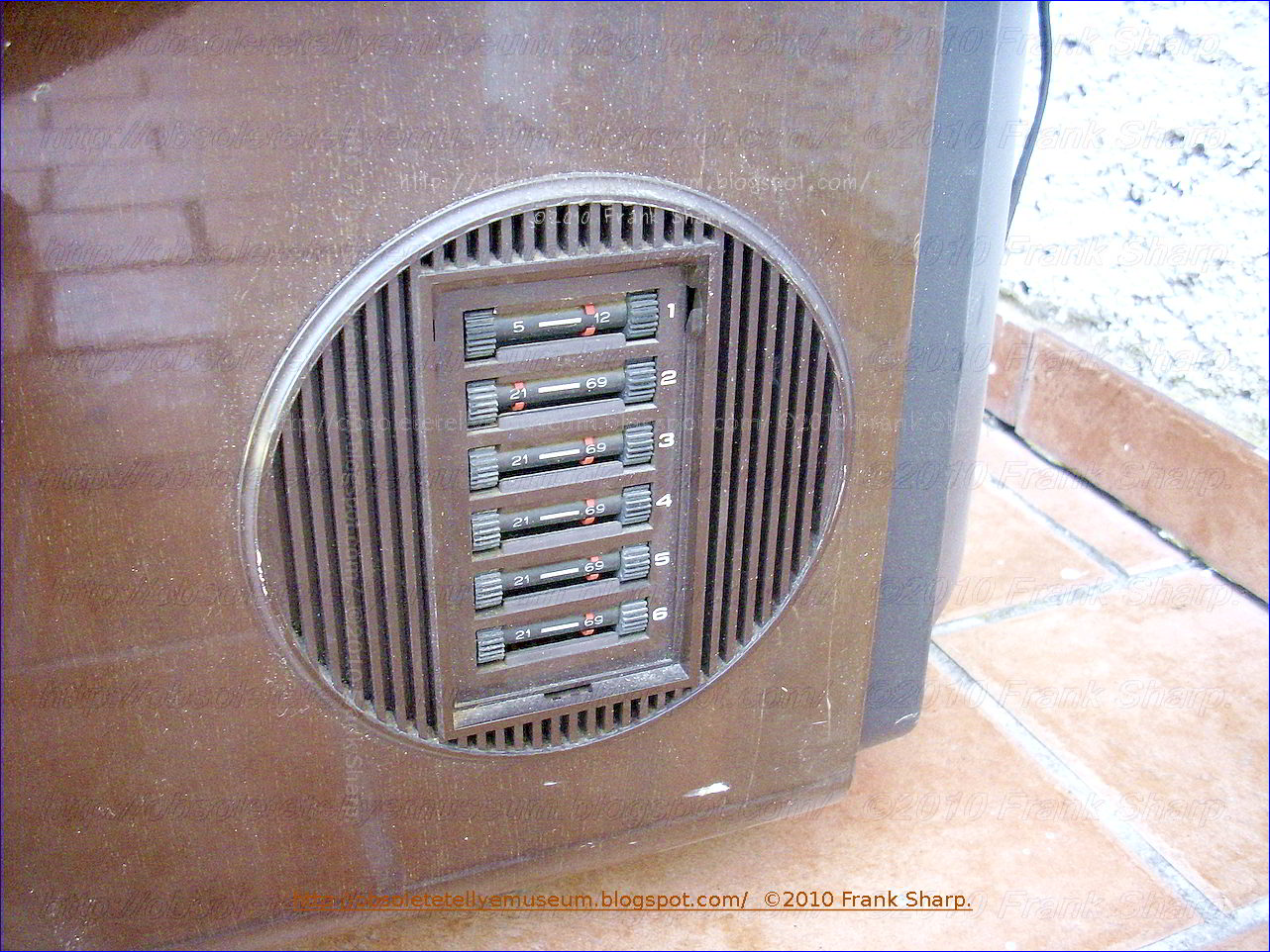


The EMERSON VULCAN 24" is a 24 (61 cm) B/W television with 6 VHF/UHF programs keyboard selected channels and tuning potentiometers drawbar side right located for every single program.
ALL commands are manual perfomed with knobs and rotatable knobs for Volume, Brightness, Contrast and On/OFF switch.
- The set is first EMERSON B/W big screen entirely featured with semiconductors and units in modular fashion.
The mechanical turret
approach to television tuning has been used almost exclusively for the
past over 60 years. Even though replete with the inherent disadvantages of
mechanical complexity, unreliability and cost, such apparatus has been
technically capable of performing its intended function and as a result
the consumer has had to bear the burdens associated with the device.
However, with the " recent " Broadcast demands for parity of tuning for
UHF and VHF channels, the increasing number of UHF and cable TV stations
have imposed new tuning performance requirements which severely tax the
capability of the mechanical turret tuner. Consequently, attempts are
now being made to provide all electronic tuning to meet the new
requirements.
The invention relates to a tuning unit with bandswitch for high
frequency receivers, especially radio and television receivers, having a
potentiometer system for the control of capacity diodes, the said
potentiometer system consisting of a plurality of parallel resistance
paths along which wiper contacts can be driven by means of screw
spindles disposed adjacent one another in a common insulating material
housing in which a bandswitch formed of metal rods is associated with
each tuning spindle.
In these tuning units, the working voltages of the capacity diodes in
the tuning circuits are recorded once a precise tuning to the desired
frequency has been performed. A potentiometer tuning system has great
advantages over the formerly used channel selectors operating with
mechanically adjustable capacitors (tuning condensers) or mechanically
adjustable inductances (variometers), mainly because it is not required
to have such great precision in its tuning mechanism.
Tuning units with bandswitches formed of variable resistances and
combined with interlocking pushbuttons controlling the supply of
recorded working voltages to capacity diodes are known. Channel
selection is accomplished by depressing the knobs, and the tuning or
fine tuning are performed by turning the knobs. The resistances serving
as voltage dividers in these tuning units are combined into a component
unit such that they are in the form of a ladderlike pattern on a common
insulating plate forming the cover of the housing in which the tuning
spindles and wiper contacts corresponding to the variable resistances
are housed. The number of resistances corresponds to the number of
channels or frequencies which are to be recorded. The wiper contact
picks up a voltage which, when applied to the capacity diodes determines
their capacitance and hence the frequency of the corresponding
oscillating circuit. The adjustment of the wipers is performed by
turning the tuning spindle coupled to the tuning knob. By the depression
of a button the electrical connection between a contact rod and a
tuning spindle is brought about and thus the selected voltage is applied
to the capacity diodes. Since the push buttons release one another, it
is possible simply by depressing another button to tune to a different
receiving frequency or a different channel, as the case may be.
Moreover, using this arrangement, the only indication--during
adjustment--of which channel is selected is by station identification.
- The set is build with a Modular chassis design because as modern television receivers become more complex the problem of repairing the receiver becomes more difficult. As the number of components used in the television receiver increases the susceptibility to breakdown increases and it becomes more difficult to replace defective components as they are more closely spaced. The problem has become even more complicated with the increasing number of color television receivers in use. A color television receiver has a larger number of circuits of a higher degree of complexity than the black and white receiver and further a more highly trained serviceman is required to properly service the color television receiver.
Fortunately for the service problem to date, most failures occur in the vacuum tubes used in the television receivers. A faulty or inoperative vacuum tube is relatively easy to find and replace. However, where the television receiver malfunction is caused by the failure of other components, such as resistors, capacitors or inductors, it is harder to isolate the defective component and a higher degree of skill on the part of the serviceman is required.
Even with the great majority of the color television receiver malfunctions being of the "easy to find and repair" type proper servicing of color sets has been difficult to obtain due to the shortage of trained serviceman.
At the present time advances in the state of the semiconductor art have led to the increasing use of transistors in color television receivers. The receiver described in this application has only two tubes, the picture tube and the high voltage rectifier tube, all the other active components in the receiver being semiconductors.
One important characteristic of a semiconductor device is its extreme reliability in comparison with the vacuum tube. The number of transistor and integrated circuit failures in the television receiver will be very low in comparison with the failures of other components, the reverse of what is true in present day color television receivers. Thus most failures in future television receivers will be of the hard to service type and will require more highly qualified servicemen.
The primary symptoms of a television receiver malfunction are shown on the picture tube of the television receiver while the components causing the malfunction are located within the cabinet. Also many adjustments to the receiver require the serviceman to observe the screen. Thus the serviceman must use unsatisfactory mirror arrangements to remove the electronic chassis from the cabinet, usually a very difficult task. Further many components are "buried" in a maze of circuitry and other components so that they are difficult to remove and replace without damage to other components in the receiver.
Repairing a modern color television receiver often requires that the receiver be removed from the home and carried to a repair shop where it may remain for many weeks. This is an expensive undertaking since most receivers are bulky and heavy enough to require at least two persons to carry them. Further, two trips must be made to the home, one to pick up the receiver and one to deliver it. For these reasons, the cost of maintaining the color television receiver in operating condition often exceeds the initial cost of the receiver and is an important factor in determining whether a receiver will be purchased.
Therefore, the object of this invention is to provide a transistorized color television receiver in which the main electronic chassis is easily accessible for maintenance and adjustment. Another object of this invention is to provide a transistorized color television receiver in which the electronic circuits are divided into a plurality of modules with the modules easily removable for service and maintenance. The main electronic chassis is slidably mounted within the cabinet so that it may be withdrawn, in the same manner as a drawer, to expose the electronic circuitry therein for maintenance and adjustment from the rear closure panel after easy removal. Another aspect is the capability to be serviced at eventually the home of the owner.
- This TV chassis was even fitted in other models and was produced for a few as the interests concentrated in Color Tvs.
- The set is fabricated in Firenze (Italy) by Giovanni BORGHI EMERSON Firm which activity was after acquired by Guido BORGHI son of Giovanni BORGHI.In 1973, his father entrusted him with the management of Emerson, the television manufacturer, of which he became president. The company, in which the Japanese Sanyo had entered after , subsequently due to conflicts between Guido Borghi and the Japanese partners went into crisis and was placed in liquidation in 1980.
Emerson History:
- Emerson Electronics S.p.A., better known as Emerson, was an Italian manufacturer of consumer electronics based in Florence.
The origins of the company date back to 1929, when on the initiative of Mr. Aldobrando Saccardi the sole proprietorship Saccardi Radio was founded in Florence, with headquarters in via Porta Rossa 39/r, which began its activities as the exclusive Radiotelefunken agent, as a concessionaire and repairer of other brands (Phonola, Magnadyne, Geloso, etc.) and with the handcrafted construction of small tube radios.
In March 1950, another shareholder, Dr. Cesare Campagnano, joined Saccardi's company and, transformed into SICART, began a collaboration with the American Emerson Radio & Phonograph Corp. SICART, with headquarters in viale Fratelli Rosselli 61, Emerson licensee and its exclusive distributor for Italy, marketed radios and televisions (assembled with frames imported from the United States) with the homonymous brand produced by the Gold Plated company Fabbriche Riunite of Casalmaggiore, in the province of Cremona. From the 1960s until its closure, SICART would later house Europhon's assistance and sales.
In 1956, the company was transformed into a joint-stock company and assumed the company name Emerson Electronics S.p.A.. The independent industrial activities were subsequently started by the American parent company, with the production of radios, televisions, record players and various electronic components, which initially amounted to 60 -70 prices per day, and the headquarters changed several times until it was located in via Bardazzi, in the Novoli area. The company had flourishing moments around 1961-63, and in 1968, it bought the use of the Emerson brand from the American house and leased the other DuMont brand.
In 1969, Campagnano, holder of 49% of the shares of Emerson, sold the same to the Milanese entrepreneur Giovanni Borghi. Borghi, the following year, in 1970, also took over the shares held by Saccardi, with whom disagreements had arisen regarding the construction of a second production plant. Emerson, under Borghi's ownership, grew both in economic-financial and productive terms, and in terms of employees, thus becoming one of the main Italian companies in the electronics sector: in 1972, together with Geloso of Milan and IREL of Genoa, it formed a consortium called Fabbriche Italiane Riunite Elettroniche e Meccaniche (FIREM), based in the Ligurian capital, and chaired by Borghi. The following year, in 1973, he left the position of president of Emerson to entrust it to his son Guido.
The growth in the turnover of the Tuscan company was remarkable, which went from about 8 billion lire in 1973 to almost 50 billion in 1978, in contrast with the other national companies in the sector, which starting from the second half of the seventies difficulties due to declines in turnover and contraction of market shares. The contraction of market shares was mainly due to the introduction of color television in Italy which took place late compared to other European countries, which prevented the ability to build the prearranged devices: in In this context, Emerson distinguished itself by starting the production of color televisions as early as 1974.
In 1977, the new factory built in Siena, in the Isola d'Arbia area, was inaugurated, a modern plant for the production of color televisions, which employed about 550 people, in addition to the 130 employed in the Florentine factory.
In 1978, a financial crisis loomed which ended with the entry of a new shareholder, the Japanese multinational Sanyo, which acquired 34% of the capital.
Through this operation, Emerson acquired new technologies and started integrated productions with Sanyo frames and its own aesthetics, while for Sanyo the aim was to facilitate the entry of its products into the European market.
The entry of the new foreign shareholder led to Emerson's marketing of computers and high-fidelity stereophonic systems under its own brand, produced by Sanyo and destined for the Italian and European markets.
The cooperation between Emerson and Sanyo was short-lived, as many misunderstandings arose between the two partners and this situation plunged the company into a serious crisis: in 1980, the Tuscan company accumulated losses of 5 billion lire, reached liquidation at the end of the same year with an attempt at an arrangement with creditors to reduce debts and avoid bankruptcy, and then it was placed in receivership.
While the liquidation and the arrangement with creditors continued, Nuova Emerson S.p.A. was set up. which attempted a relaunch, proposing an association with Indesit and Voxson, and subsequently attempting to enter REL, the national plan for the restructuring of companies in the electronic sector established in 1982 by the Ministry of Industry, from which it was excluded.
In 1985 there was interest from another Japanese electronics giant, Pioneer, to buy the Tuscan company's brand and factories, which however did not lead to anything concrete.
The Siena plant and the Emerson brand were taken over in 1988 by Ultravox Siena, a subsidiary of the Milanese Ultravox and REL.
This company was active until 1999, when it had to close due to bankruptcy, and subsequently the plant passed to a newco controlled by the German Galaxis Holding GmbH which continued the activity, Galaxis Produzione S.p.A., which in turn went bankrupt in 2001
Emerson Electronics S.p.A., a company with registered office in Florence, and two production plants in Florence and Siena, manufactured Emerson brand televisions and marketed other types of products under the same name, such as video recorders, hi-fi systems and calculators.
In 1979, the company had 836 employees in the two plants, and achieved a turnover of 57.5 billion lire and an operating loss of 58 million.
In the television market, Emerson was fourth in Italy after Philips, Grundig and Telefunken, and the sale of such products constituted 90% of its turnover.
20% of television sales were made abroad, most of them in West Germany.
Sponsorships
Emerson was a sponsor of Pallacanestro Varese in the 1978-79 and 1979-80 seasons.
 The Milan industrialist Giovanni Borghi founded
the IGNIS brand of household appliances. His factories would turn out
one appliance every eight seconds, and make billions selling them to
Italy's exploding middle class. Borghi was famous for his early
support of cycling, and his yellow IGNIS jerseyed squadra won more than a
few great races in the late fifties and early sixties.
The Milan industrialist Giovanni Borghi founded
the IGNIS brand of household appliances. His factories would turn out
one appliance every eight seconds, and make billions selling them to
Italy's exploding middle class. Borghi was famous for his early
support of cycling, and his yellow IGNIS jerseyed squadra won more than a
few great races in the late fifties and early sixties.Borghi was aggressive, flamboyant and flashy. And he took care of his stars - famously buying Spanish sprinter Miguel Poblet a Lancia convertible after his Milan San Remo win. On top of his 25 million lire per year salary.
illumination: refrigerators insulated with Polyurethane foam were much more
efficient and capacious than those hand-filled with mineral wood.
His refrigerators Group, Ignis, developed internally this technology and the
related equipment, a suitable alternative to the imported foam dispensers, which
were difficult to get, fix and maintain, stimulating an industrial supply of
similar machines.

Borghi kept control of IGNIS in the family. In the paternalistic Italian industrial model - like Ferrari, Maserati or Campagnolo. He later turned the reins over to his son, who in turn finally sold the company to Dutch conglomerate, Philips.
When Philips decided to get into the major household appliances
market, its procedure was to buy increasing quantities of these goods from the Italian firm, Ignis, then at the height of its prosperity.
Once it became the principal client of the manufacturer, it took over supplying the latter by purchasing 50 percent of its capital. It took over the firm completely in 1972, to the satisfaction of the founder of Ignis, Giovanni Borghi.
The American company in 1991, acquired the whole of the Ignis, which became Italy s.r.l, Whirlpool and Whirlpool Europe later, and since then is a part of the group, which produced household appliances in the Italian plants, still active
BORGHI DIED IN 1975.
Borghi is still remembered in Italia. RAI even aired TV miniseries about his life this past year, "Mister Ignis".
(To see the Internal Chassis Just click on Older Post Button on bottom page, that's simple !)
Further NOTES and readings.
^ ANTICHE DITTE RADIO A FIRENZE, su iw5csj.jimdofree.com. URL consultato il 16 aprile 2021.
^ Ditta Saccardi Firenze, su carlobramantiradio.it. URL consultato il 16 aprile 2021.
^ Inserzione pubblicitaria pubblicata da Emerson Electronics S.p.A. sulla rivista Epoca n. 988 del 31 agosto 1969
^ Annuario industriale della Provincia di Milano, Unione Industriale Fascista della Provincia di Milano, 1933, p. 217.
^ E. Parente, SICART "La Voce del Mondo" mod. 232 radiofonografo, in Antique Radio Magazine, n. 139, Club Antique Radio Magazine, settembre-ottobre 2017, pp. 10-15.
^ Gazzetta Ufficiale del Regno d'Italia, Foglio delle inserzioni n. 20 del 25 gennaio 1936, p. 106
^ Da non confondere con la SICART (Società Italiana Commercio Apparecchi Radio e di Televisione) di Milano, fondata nel 1931, che commercializzava radioricevitori e radiofonografi con il marchio La Voce del Padrone, fino alla sua messa in liquidazione avvenuta nel 1936.[5][6][7]
Archivio Emerson.
^ XVIII Mostra nazionale della radio e televisione. Elenco degli espositori in L'Antenna n.9 del settembre 1951, p. V
^ Inserzione pubblicitaria della Emerson Radio and Television pubblicata sulla rivista L'Antenna n. 12 del dicembre 1949, p. 536
^ Inserzione pubblicitaria della SICART pubblicata sulla copertina della rivista Radio Industria Televisione n. 177 del settembre 1951
^ B. Cappello, La fabbrica dell’oro matto, in Preziosa Magazine, 29 aprile 2015. URL consultato il 17 aprile 2021.
^ Sentenze e note, in Rivista di diritto industriale, n. 5, Giuffrè, settembre-ottobre 1956, p. 189.
^ Kompass, vol. 2, Etas, 1971, p. 1473.
^ G. Migliorino, Nasce la superazienda elettronica, in Corriere della Sera, 17 ottobre 1972, p. 7.
^ Entra in scena Borghi junior, in Corriere della Sera, 15 dicembre 1973, p. 6.
Emerson in quinta marcia, in Selezione di tecnica. Radio TV HiFi Elettronica, n. 3, JCS, marzo 1979, p. 266.
^ L'Emerson (Borghi) insieme ai giapponesi, in Corriere della Sera, 20 gennaio 1978, p. 27.
- La Sanyo (giapponese) acquista il 30 per cento della Emerson, in La Stampa, 20 gennaio 1978, p. 16.
- ^ G. Mazzuca, Forse Sanyo divorzierà da Emerson dopo solo due anni di «matrimonio», in Corriere della Sera, 16 ottobre 1980, p. 12.
- ^ G. Mazzuca, L'Emerson sarà messa in liquidazione, in Corriere della Sera, 22 ottobre 1980, p. 13.
- ^ M. Salvatorelli, Nasce in Italia un colosso elettronico, in La Stampa, 21 febbraio 1981, p. 10.
- ^ I GIAPPONESI DELLA PIONEER INTERVENGONO PER LA EMERSON, in La Repubblica, 28 luglio 1985, p. 30. URL consultato il 17 aprile 2021.
- ^ Nuovo stabilimento a Siena, in L'Unità, 15 gennaio 1988, p. 12.
- ^ F. Saulino, DUE MILIARDI A DIPENDENTE PER 'SALVARE' LA EMERSON, in La Repubblica, 6 febbraio 1988, p. 55. URL consultato il 15 aprile 2021.
- ^ 1898/1999 ULTRAVOX SIENA SPA, su portalecreditori.it. URL consultato il 14 aprile 2021.
- ^ CONTRATTAZIONE PROVINCIALE SETTORE METALMECCANICO (1991-1998), su archivio.movimentooperaio.com.
- ^ V. Ravizza, Borghi, l'amico dei giapponesi, in La Stampa, 29 maggio 1980, p. 15.
- R. Delfiol (a cura di), Archivio Emerson (Inventario) (PDF), Firenze, Soprintendenza Archivistica e Bibliografica della Toscana, 2000, nota 1, pp. 3-4.
External LINKS:
- Emerson Electronics; Firenze, su radiomuseum.org. URL consultato il 16 aprile 2021.
- Emerson, su aireradio.org. URL consultato il 16 aprile 2021.


