

CRT TUBE PHILIPS A50-120W
TELEVISION TUBE A50- 120W/R
QUICK REFERENCE DATA
50cm (20in) direct viewing television tube With metal backed screen
and reinforced envelope. A separate safety screen is not required.
Suitable for use in receivers with push-through presentation. This
tube is fitted with a ring trap base:
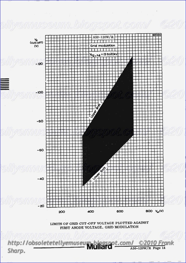
Deflection angle 110 deg
Focusing Electrostatic
Light transmission (approx.) ’ ’ 45 %
Maximum overall length 319 mm
This data should be read in conjunction with GENERAL OPERATIONAL
RECOMMENDATIONS — TELEVISION PICTURE TUBES
HEATER
Suitable for series or parallel operation
Vh 6 . 3 V
Ib 300 mA
The limits of heater voltage and current are contained in ‘General
Operational Recommendations — Television Picture Tubes’.
Note - applies to series operation only
The surge heatervoltage must not exceed 9.5V r.m.s. when the supply is
switched on. A current limiting device maybe necessary in the circuit, to
ensure that this voltage is not exceeded.
OPERATING CONDITIONS
V 32’ £4 20 20 IN
V a3 (focus electrode control range) 0 to 400 0 to 400 V
V 400 500 V
a1Vg for visual extinction of focused raster -40 to -77 ~50 to -93 V
Vk for visual extinction of focused raster 36 to 66 45 to 80 V
For cathode modulation, all voltages are measured with respect to the
grid .
SCREEN (Metal backed)
Fluorescent colour White
Light transmission (EPPFOX-) 45 96


The range of focus voltage shown in ‘Operating Conditions’ results in opti-
mum overall focus at a beam current of 250UA. In general, acceptable
resolution will be obtained with a fixed focus voltage.
DEFLECTION (Magnetic)
Diagonal deflection angle E 110 deg
Horizontal deflection angle 98 deg
Vertical deflection angle ' ' 81 ~ deg
The deflection coils should be designed to provide a pull—back of 4 .0mm
on a. nominal tube . '
CAPACITANCES
cg_au 7.0 pl?‘
ck_an 5.0 pF
ca2’.a4_M 850 to 1300; pF <- br="">"a2,a4-B 50° PF
EXTERNAL CONDUCTIVE COATING
This tube has an external conductive coating, M, and in accordance with
the General Operational Recommendations this should be connected directly
to pin 5 and not to chassis. The electrical connection to this coating must
be made within the area specifiedon the tube outline drawing.
The capacitance of this coating to the final anode is used to provide smoothing for the
e.h.t. supply.
For flashover protection of the receiver, parallel spark gaps are included
for all the electrodes in the base of this tube, and the common connection
is made to pin 5. These spark gaps are intended as part of a system for
full flashover protection. A direct connection must always be made from
pin 5 to chassis, and the external conductive coating returned to chassis
only via pin 5, using short leads. Any electrode supplied directly from a
high energy source (such as the h.t. line) should be provided with a series
resistor.
RASTER CENTRING
See note under this heading in ‘General Operational Recommendations —
Television Picture Tubes‘.
Centring magnet field intensity . , 0 to 800 A/m
Maximum distance of centre of
centring field from reference line 57 mm
Adjustment of the centring magnet should not be such that a general reduction in brightness of the raster occurs .
TELEVISION TUBE MOUNTING POSITION
Any. The tube socket should not be rigidly motmted but should have
flexible leads and be allowed to move freely. The bottom circumference of the
base shell will fall within a circle of 40mm diameter which is centred on
the perpendicular from the centre of the face.
This tube is fitted with a pin protector in order to avoid damage to the
glass base due to bending of the base pins whilst handling the tube.
It is advisable to keep this pin protector on the base imtil it can be replaced
by the socket after installation of the tube in any equipment.
No comments:
Post a Comment
The most important thing to remember about the Comment Rules is this:
The determination of whether any comment is in compliance is at the sole discretion of this blog’s owner.
Comments on this blog may be blocked or deleted at any time.
Fair people are getting fair reply. Spam and useless crap and filthy comments / scrapers / observations goes all directly to My Private HELL without even appearing in public !!!
The fact that a comment is permitted in no way constitutes an endorsement of any view expressed, fact alleged, or link provided in that comment by the administrator of this site.
This means that there may be a delay between the submission and the eventual appearance of your comment.
Requiring blog comments to obey well-defined rules does not infringe on the free speech of commenters.
Resisting the tide of post-modernity may be difficult, but I will attempt it anyway.
Your choice.........Live or DIE.
That indeed is where your liberty lies.
Note: Only a member of this blog may post a comment.