


This Units system provides the services for all remote control functions.
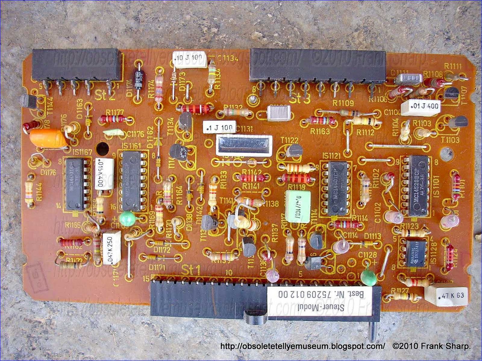
Command Unit: Steuer Modul 75 209 012 00
Converter Unit: Wandler Modul 72 209 011 00
SABA ULTRACOLOR T6787 Telecommander CM CHASSIS CM110 75 206 000 30 UniLineReceiver tuning circuit with automatic search and AFC using common capacitor:

The most common type of voltage-dependent variable-reactance device is a diode which has an interelectrode capacitance directly proportional to its reverse-bias voltage, commonly referred to as a "Varicap" or "varactor" diode. By placing one or more such diodes in the frequency-selecting portion of a tuner, station selection may be achieved by progressively increasing or decreasing the voltage applied to the diode(s) until the desired frequency is obtained. Moreover, by combining a varactor-diode tuner with a progressively variable DC control voltage generator, a signal detector, and a feedback control loop, a satisfactory solid-state signal-seeking system may be created.
In conventional signal-seeking systems employing varactor diodes, however, a temporary loss of signal resulting from "airplane flutter," transmitter failure, etc., or even receiver deenergization, varies (or eliminates) the control voltage and/or interrupts the recognition signal from the signal detector and therefore sends the system seeking for a new station. The addition of complex delay circuitry for temporarily maintaining the DC control voltage not only adds appreciable cost to the system but also does not compensate for the loss of control voltage due to receiver deenergization such as when the receiver is turned off for a while.
It is therefore an object of the invention to provide a new and improved signal-seeking system for a voltage-controlled tuner.
It is a more specific object of the invention to provide such a new and improved signal-seeking tuning system which is immune to undesired signal-seeking resulting from a temporary loss of signal or receiver deenergization.
A station finder which switches to automatic frequency control during automatic finding in case of reception of a transmitter and, if desired, continues to find a transmitter some time later with the frequency control switched off.
1. A receiver tuning circuit f

2. A receiver tuning circuit as claimed in claim 1, wherein said operating device has a supply lead and the time constant circuit is coupled to the supply lead of the operating device.
3. A receiver tuning circuit as claimed in claim 1, wherein the detection circuit is coupled to an output of a frequency detector and includes a means for preventing pulling in on the same transmitter upon activation of said search tuning circuit.
Description:
The invention relates to a receiver tuning circuit including a search tuning circuit which can be activated by a control device in which the search tuning circuit is automatically switched off when a received station is detected by a detection circuit and an automatic frequency control circuit is switched on, and in which a time constant circuit changes the state of the receiver tuning circuit after a certain time.A receiver tuning circuit of the kind described above is known from German Offenlegungsschrift 2,023,352 which after activation of the search tuning stops the search action when a transmitter transmitting a pilot signal is received and switches on an automatic frequency control circuit. The search tuning circuit must again be a
This known tuning circuit is only suitable for special receivers. An object of the invention is to provide a tuning circuit which is more suitable for other receiver types.
To this end a receiver tuning circuit of the kind described in the preamble according to the invention is characterized in that the time constant circuit is incorporated in the tuning circuit in such a manner that again and again it switches on the search tuning circuit a certain time after having automatically switched it off and switches off the automatic frequency control as long as the search tuning circuit is maintained operative with the aid of the operating device.
By using the step according to the invention a receiver is obtained which upon activation of the search tuning circuit receives without distortion transmitter after transmitter each during a time determined by the time constant circuit. The search tuning can be rendered inactive with the aid of the operating device after the desired station has been found. The tuning circuit is very suitable for radio or television receivers for domestic use.
SABA ULTRACOLOR T6787 Telecommander CM CHASSIS CM110 75 206 000 30 UniLineMethod and system for increasing the number of instructions transmitted in digital systems, I.A. in systems for remote control of television receiver:ITT VOLTAGE SYNTHESIZER TUNING SEARCH SYSTEM
Method of increasing the number of instructions according to the invention consists therein that withing the command signal (6) additional instructions are transmitted, which after being decoded in the instruction decoder (1) and processed in the strobbin signal generation circuit (4) strobes the operation of additional controlled units (5) and control the transmission of the signal through the register (2) to the controlled units (3).
 In the system according to the invention, between one of the outputs od the instruction decoder (1) and the unit (3) to be controlled the register (2) is connected, provided with an additional input for the record inhibiting instruction (10), whereas to the second output of the instruction decoder (1) the strobbing signal generation circuit (4) is connected aimed at controlling the additional controlled units (5). The register (2) and the strobbing signal generation circuit (4), employed in the system according to the invention, can be built-in into each of the integrated circuits or made in form of a separate integrated circuit.
1. A method of increasing the number of instructions transmitted in remote control systems of television receivers and the like in which decoded signals directly control receiving units, comprising transmitting coded instructions in a command signal (6), decoding said instructions into a first part of an instruction signal (8), processing said first part of the instruction signal (8) in a strobing signal generation circuit (4) to provide a first signal (10) in a form for enabling the transmission of a control signal (7) through a register (2) in the form of a stored signal (11) to first receiving units (3) to be controlled while simultaneously providing a second signal (9) in a form for blocking the reception of one of said instruction signal (8) and said control signal (7) by additional receiving units (5) to be controlled, transmitting an additional coded instruction in said command signal, decoding said additional instruction into a second part of the instruction signal (8), processing said second part of the instruction signal (8) in said strobing signal generation circuit (4) to provide said first signal (10) in a form for blocking furthe
Description:
This invention relates to a method and a system making it possible to increase the number of instructions transmitted in systems of remote control of television or radio receivers, and the like.
One of the known remote control systems is a system based on integrated circuits of the firm ITT. Similarly as in other systems, the instructions transmitted remotely are coded by a transmitter, for instance SAA1024, in an electric signal modulating a wave being able to propagate in the environment. In the receiver for instance SAA 1130, the coded electric signal is received and gives at its outputs the completely decoded output information signal and decoded output control signals.
In known application notes of the firm ITT the decoded output control signals control directly the receiving devices SAA1021, SAA1020. The decoder of information transmits also other decoded control signals, for instance analog adjustment signals, turning a signal on the power supply, and other signals necessary for the operation of the system. A certain part of the total number of instructions transmitted in the coded input signal constitutes a group of additional instructions for decoding by an additional instructions decoder controlled by the output signal.
The method of increasing the number of instructions transmitted in digital systems, i.a. in remote control systems of television receivers, according to the invention comprises transmitting in the control signal additional instructions which, on being decoded in an instruction decoder and after processing in a circuit for generating strobing signals, strobe the operation of additional controlled devices and control the transmission of the control signal through a register to main controlled units. In the system according to the invention two variants of operation of the system are distinguished. In the first variant an inhibiting signal coming out of the strobing signal generation circuit enables storage by the register of the real values being decoded, the output control signals, and controls with a suitable signal the main controlled units, while blocking by another suitable signal the additional controlled devices. In the second variant of the method according to the invention, after transmission of the additional instruction in the input signal, the storage inhibiting signal inhibits the register which stores the previous instruction and interruptedly controls the controlled unit, whereby simultaneously another strobing signal enables the additional controlled units to receive the controlling instruction.
In the system according to the invention the controlling of additional units is performed in the course of uninterrupted operation of controlled units.
In the system for increasing the number of instructions transmitted in digital systems, i.a. in remote control systems of television receivers, according to the invention, between one output of the instruction decoder and first controlled units a register is connected, having an additional input for a recording inhibiting signal, whereas to another output of the instruction decoder a strobing signal generation circuit is connected for controlling additional controlled units.
The inputs of the additional controlled units are connected with any outputs of the instruction decoder and with outputs of a register of the strobing circuit. The register and the strobing generation circuit, employed in the system according to the invention, can be built-in in one integrated circuit or may be made in the form of separate integrated circuits.
Referring to the aforement ioned system of the firm ITT, the list of instructions thereof comprises 10 instructions used for basic servicing of the television receivers, 16 instructions for program selection and 5 additional instructions. In the method according to the invention, by using all the additional instructions, additionally 5×16 instructions are obtained. The number of all useful instructions in the method according to the invention amounts to 10+16+5×16=106 instructions, and thus by 75 instructions more than it was foreseen by the manufacturer of said systems.
Employing of the method and the system in a simple constructional arrangement enables one to multiply the number of transmitted signals, and simultaneously the number of units to be controlled. With reference to the system of the firm ITT, based on integrated circuits SAA1024, SAA1130, SAA1021, SAA1020, this enables one to employ additionally a teletext, a time programmer, an electronic watch, remote control of a radio receiver, tuning of a second head to observe another program, and other uses that were not possible and not foreseen by the manufacturer of said circuits.
The method and system according to the invention will be now described by means of an exemplary embodiment with reference to the accompanying drawing, wherein:
FIG. 1 is the block diagram of the system, and
FIG. 2 is the connection diagram of the strobing circuit.
The system of an instruction invention consists of the decoder 1, one output of which is connected through a register 2 with units 3 to be controlled. Another output of the instruction decoder 1 is connected with a strobing signal generation system 4 to the output of which is connected an additional controlled unit 5 having inputs connected with either output of the decoder 1.
The strobing circuit 4 is equipped with a decoder 12 an output 13 of which is connected with the clearing input of a register 14, and outputs 15, 16, 17, 18 of which are connected with the recording inputs of the register 14. The registers outputs 19, 20, 21, and 22, however, are connected with the additional unit 5 (FIG. 1) and with an adding gate 23, the output 10 of which is connected with the record inhibiting input of the register 14 and with the record inhibiting input of the register 2.
In the method according to the invention, the control signal 6 received by the instruction decoder 1 is decoded into groups of instructions 7 and 8. The instructions 8 after being processed in the strobing signal generating circuit 4 strobe the operation of additional devices 5 in the form of a signal 9, and in the form of the inhibiting signal 10 they control the operation of the register 2. A part of instructions 8, after processing in the strobbing circuit 4, enables with the signal 10 the transmission of the instructions 7 through the reg ister 2 to the controlled units 3 in the form of the decoded control signal 11. Simultaneously, the decoded instruction 8 blocks with the strobing signal 9 the receiving of instructions 7 or 8 by the additional units 5 to be controlled. After transmitting the additional information from the second part of the instructions 8 in the signal 6, the instruction 8 after processing in the strobing signal generating circuit 4 blocks with the signal 10 the register 2, which stores the previous signal 7 and uninterruptedly controls the units 3 to be controlled, and simultaneously enables the additional controlled units 5 to receive instructions 7 or 8. The transmission of an erasing instruction in the signal 6 causes the return to the previous way of transmission and the turning off of the additional units 5.
The controlling of additional units 5 in the method according to the invention by means of the signal 7 or 8 is performed in the course of uninterrupted controlling of the units 3 by means of the signal 11 from the register 2.
One of the known remote control systems is a system based on integrated circuits of the firm ITT. Similarly as in other systems, the instructions transmitted remotely are coded by a transmitter, for instance SAA1024, in an electric signal modulating a wave being able to propagate in the environment. In the receiver for instance SAA 1130, the coded electric signal is received and gives at its outputs the completely decoded output information signal and decoded output control signals.
In known application notes of the firm ITT the decoded output control signals control directly the receiving devices SAA1021, SAA1020. The decoder of information transmits also other decoded control signals, for instance analog adjustment signals, turning a signal on the power supply, and other signals necessary for the operation of the system. A certain part of the total number of instructions transmitted in the coded input signal constitutes a group of additional instructions for decoding by an additional instructions decoder controlled by the output signal.
The method of increasing the number of instructions transmitted in digital systems, i.a. in remote control systems of television receivers, according to the invention comprises transmitting in the control signal additional instructions which, on being decoded in an instruction decoder and after processing in a circuit for generating strobing signals, strobe the operation of additional controlled devices and control the transmission of the control signal through a register to main controlled units. In the system according to the invention two variants of operation of the system are distinguished. In the first variant an inhibiting signal coming out of the strobing signal generation circuit enables storage by the register of the real values being decoded, the output control signals, and controls with a suitable signal the main controlled units, while blocking by another suitable signal the additional controlled devices. In the second variant of the method according to the invention, after transmission of the additional instruction in the input signal, the storage inhibiting signal inhibits the register which stores the previous instruction and interruptedly controls the controlled unit, whereby simultaneously another strobing signal enables the additional controlled units to receive the controlling instruction.
In the system according to the invention the controlling of additional units is performed in the course of uninterrupted operation of controlled units.
In the system for increasing the number of instructions transmitted in digital systems, i.a. in remote control systems of television receivers, according to the invention, between one output of the instruction decoder and first controlled units a register is connected, having an additional input for a recording inhibiting signal, whereas to another output of the instruction decoder a strobing signal generation circuit is connected for controlling additional controlled units.
The inputs of the additional controlled units are connected with any outputs of the instruction decoder and with outputs of a register of the strobing circuit. The register and the strobing generation circuit, employed in the system according to the invention, can be built-in in one integrated circuit or may be made in the form of separate integrated circuits.
Referring to the aforement
Employing of the method and the system in a simple constructional arrangement enables one to multiply the number of transmitted signals, and simultaneously the number of units to be controlled. With reference to the system of the firm ITT, based on integrated circuits SAA1024, SAA1130, SAA1021, SAA1020, this enables one to employ additionally a teletext, a time programmer, an electronic watch, remote control of a radio receiver, tuning of a second head to observe another program, and other uses that were not possible and not foreseen by the manufacturer of said circuits.
The method and system according to the invention will be now described by means of an exemplary embodiment with reference to the accompanying drawing, wherein:
FIG. 1 is the block diagram of the system, and
FIG. 2 is the connection diagram of the strobing circuit.
The system of an instruction invention consists of the decoder 1, one output of which is connected through a register 2 with units 3 to be controlled. Another output of the instruction decoder 1 is connected with a strobing signal generation system 4 to the output of which is connected an additional controlled unit 5 having inputs connected with either output of the decoder 1.
The strobing circuit 4 is equipped with a decoder 12 an output 13 of which is connected with the clearing input of a register 14, and outputs 15, 16, 17, 18 of which are connected with the recording inputs of the register 14. The registers outputs 19, 20, 21, and 22, however, are connected with the additional unit 5 (FIG. 1) and with an adding gate 23, the output 10 of which is connected with the record inhibiting input of the register 14 and with the record inhibiting input of the register 2.
In the method according to the invention, the control signal 6 received by the instruction decoder 1 is decoded into groups of instructions 7 and 8. The instructions 8 after being processed in the strobing signal generating circuit 4 strobe the operation of additional devices 5 in the form of a signal 9, and in the form of the inhibiting signal 10 they control the operation of the register 2. A part of instructions 8, after processing in the strobbing circuit 4, enables with the signal 10 the transmission of the instructions 7 through the reg
 ister 2 to the controlled units 3 in the form of the decoded control signal 11. Simultaneously, the decoded instruction 8 blocks with the strobing signal 9 the receiving of instructions 7 or 8 by the additional units 5 to be controlled. After transmitting the additional information from the second part of the instructions 8 in the signal 6, the instruction 8 after processing in the strobing signal generating circuit 4 blocks with the signal 10 the register 2, which stores the previous signal 7 and uninterruptedly controls the units 3 to be controlled, and simultaneously enables the additional controlled units 5 to receive instructions 7 or 8. The transmission of an erasing instruction in the signal 6 causes the return to the previous way of transmission and the turning off of the additional units 5.
The controlling of additional units 5 in the method according to the invention by means of the signal 7 or 8 is performed in the course of uninterrupted controlling of the units 3 by means of the signal 11 from the register 2.
No comments:
Post a Comment
The most important thing to remember about the Comment Rules is this:
The determination of whether any comment is in compliance is at the sole discretion of this blog’s owner.
Comments on this blog may be blocked or deleted at any time.
Fair people are getting fair reply. Spam and useless crap and filthy comments / scrapers / observations goes all directly to My Private HELL without even appearing in public !!!
The fact that a comment is permitted in no way constitutes an endorsement of any view expressed, fact alleged, or link provided in that comment by the administrator of this site.
This means that there may be a delay between the submission and the eventual appearance of your comment.
Requiring blog comments to obey well-defined rules does not infringe on the free speech of commenters.
Resisting the tide of post-modernity may be difficult, but I will attempt it anyway.
Your choice.........Live or DIE.
That indeed is where your liberty lies.
Note: Only a member of this blog may post a comment.