


The PANASONIC EURO-4 is a full digital CHASSIS implementing the DIGIT3000 chipset family from ITT/MICRONAS and is the successor of the EURO2 CHASSIS Family series from PANASONIC.
It differs from previous by the high integration and compactness compared to other digital chassis types.
The PANASONIC EURO-4 runs Quiet and good but they have had a high rate of failures caused mainly by high number of dry joint points all around the chassis and particularly in the Frame deflection section which runs discretely HOT !
PANASONIC TX-25MD4C CHASSIS EURO-4 CIRCUITS DESCRIPTIONS:
STRF6654LF51 OFF-LINE QUASI-RESONANT FLYBACK SWITCHING REGULATORS:

ments for incre
ased integration and reliability in off-line quasi-resonantflyback converters. The series incorporates a primary control and drive
circuit with discrete avalanche-rated power MOSFETs.
Covering the power range from below 25 watts up to 300 watts for
100/115/230 VAC inputs, and up to 150 watts for 85 to 265 VAC
universal input, these devices can be used in a range of applications,
from battery chargers and set top boxes, to televisions, monitors, and
industrial power supply units.
Cycle-by-cycle current limiting, under-voltage lockout with hyster-
esis, over-voltage protection, and thermal shutdown protects the power
supply during the normal overload and fault conditions. Over-voltage
protection and thermal shutdown are latched after a short delay. The
latch may be reset by cycling the input supply. Low-current startup and
a low-power standby mode selected from the secondary circuit completes
a comprehensive suite of features. The series is provided in a five-pin
overmolded TO-3P style package, affording dielectric isolation without
compromising thermal characteristics.
FEATURES
I Flyback Operation with Quasi-Resonant Soft Switching
for Low Power Dissipation and EMI
I Rugged Avalanche-Rated MOSFET
I Choice of MOSFET Voltage and rDS(on)
I Full Over-Current Protection (no blanking)
I Under-Voltage Lockout with Hysteresis
I Over-Voltage Protection
I Direct Voltage Feedback
I Low Start-up Current (<400 br="">I Low-Frequency, Low-Power Standby Operation
I Overmolded 5-Pin Package.
LA7845 Vertical Deflection Output Circuit:
Overview
The LA7845 is a vertical deflection output IC for high-
resolution television and CRT display systems that use a
bus controller system signal processing IC. It can directly
drive the deflection yoke (including the required DC
component) from the bus controller system signal
processing IC's sawtooth waveform output. Connecting
the LA7845 and a Sanyo TV bus control system signal
processing IC in the LA7615 series allows all functions of
a color television signal system to be processed by the bus
system. Since the LA7845 has a maximum deflection
current of 2.2 Ap-p, it is optimal for use in large aperture
products, and is capable of driving 33 to 37 inch class
monitors.
Features
• Low power dissipation due to the provision of a built-in
pump circuit
• Vertical output circuit
• On-chip thermal protection circuit
• Good crossover characteristics
• Supports DC coupling.
ITT VDP3108 Single-Chip Video Processor
Preamble:
The ITT VDP3108 Is the evolution of the DIGIT2000 chipset.

1. Introduction
The entire video processing and controlling for a color
TV has been developed on a single chip in 0.8m CMOS
technology. Modular design and submicron technology
allow the economic integration of features in all classes
of TV sets.
Open architecture is the key word to the new DSP generation.
Flexible standard building blocks have been defined
that offer continuity and transparency of the entire
system.
One IC contains the entire video and deflection processing
and builds the heart of a modern color TV. Its performance
and complexity allow the user to standardize
his product development. Hardware and software applications
can profit from the modularity as well as manufacturing,
system support or maintenance. The main
features are:
– low cost, high performance
– all digital video processing
– multi-standard color decoder PAL/NTSC/SECAM
– 3 composite, 1 S–VHS input
– integrated high-quality AD/DA converters
– sync and deflection processing
– luminance and chrominance
features, e.g.peaking, color transient improvement
– programmable RGB matrix
– various digital interfaces
– embedded RISC controller (80 MIPS)
– one crystal, few external components
– single power supply 5 V
– 0.8m CMOS Technology
– 68-pin PLCC or 64-pin Shrink DIL Package
1.1. System Architecture
Two main modules have been defined:
Video Processor and
Display Processor.
They are designed as silicon building blocks. Their partitioning
permits a variety of IC configurations with the aim
to satisfy the particular requirements of different applications.
Both, analog and digital interfaces, support
state of the art TV receivers as well as other environments.
Fig. 1–1 shows the block diagram of the singlechip
Video Processor which consists of both modules.

2. Functional Description
2.1. Analog Front End
This block provides the analog interfaces to all video inputs
and mainly carries out analog-to digital conversion
for the following digital video processing. A block diagram
is given in figure 2–1.
Most of the functional blocks in the front end are digitally
controlled (clamping, AGC and clock-DCO). The control
loops are closed by the Fast Processor (‘FP’) embedded
in the decoder.
2.1.1. Input Selector
Up to four analog inputs can be connected. Three inputs
are for input of composite video or S–VHS luma signal.
These inputs are clamped to the sync back porch and
are amplified by a variable gain amplifier. One input is
for connection of S–VHS carrier–chrominance signal.
This input is internally biased and has a fixed gain amplifier.
2.1.2. Clamping
The composite video input signals are AC coupled to the
IC. The clamping voltage is stored on the coupling capacitors
and is generated by digitally controlled current
sources. The clamping level is the back porch of the video
signal. S-VHS chroma is also AC coupled. The input
pin is internally biased to the center of the ADC input
range.
2.1.3. Automatic Gain Control
A digitally w
orking automatic gain control adjusts themagnitude of the selected baseband by +6/–4.5 dB in 64
logarithmic steps to the optimal range of the ADC .
The gain of the video input stage including the ADC is
213 steps/V for all three standards (PAL/NTSC/SECAM/
Y/C), with the AGC set to 0 dB.
2.1.4. Analog-to-Digital Converters
Two ADCs are provided to digitize the input signals.
Each converter runs with 20.25 MHz and has 8 bit resolution.
An integrated bandgap circuit generates the required
reference voltages for the converters.
The two ADCs are of a 2-stage subranging type.
---------------------------------------------------------------------------
TOGHETHER WITH VIDEO PROCESSING THERE IS SOUND PROCESSING WITH MSP3400C


Multistandard Sound Processor
Release Notes: The hardware description in this
document is valid for the MSP 3400C – C8 and newer
codes. Revision bars indicate significant changes
to the previous version.
1. Introduction
The MSP 3400C is designed as single-chip Multistandard
Sound Processor for applications in analog and
digital TV sets, satellite receivers and video recorders.
The MSP-family, which is based on the MSP 2400, demonstrates
the progressive development towards highly
integrated multi-functional ICs.
The MSP 3400C, again, improves function integration:
The full TV sound processing, starting
with analogsound IF signal-in, down to processed analog AF-out, is
performed in a single chip. The IC is produced in 0.8 mm
CMOS technology, combined with high performance
digital signal processing.
The MSP 3400C 0.8 m CMOS version is fully pin and
software compatible to the 1.0 m MSP 3400 and MSP
3410. The main difference between the MSP 3400C and
the MSP 3410, consists of the MSP 3410 being able to
decode NICAM signals.
2. Features of the MSP 3400C:
2.1. Features of the Demodulator and Decoder
Sections
The MSP 3400C is designed to perform demodulation
of FM-mono TV sound and two carrier FM systems according
to the German or Korean terrestrial specs.
Withcertain constraints, it is also possible to do AM-demodulation
according to the SECAM system. Alternatively, the
satellite specs can be processed with the MSP 3400C.
For FM carrier detection in satellite operation, the AMdemodulation
offers a powerful feature to calculate the
carrier field strength, which can be used for automatic
search algorithms. So, the IC facilitates a first step towards
multistandard capability with its very flexible
application and may be used in TV-sets, satellite tuners,
and video recorders.
The MSP 3400C facilitates profitable multistandard capability,
offering the following advantages:
– two selectable analog inputs (TV and SAT-IF sources)
– Automatic Gain Control (AGC) for analog input: input
range: 0.14 – 3 Vpp
– integrated A/D converter for sound-IF inputs
– all demodulation and filtering is performed on chip and
is individually programmable
– no external filter hardware is required
– only one crystal clock (18.432 MHz) is necessary
– FM carrier level calculation for automatic search algorithms
and carrier mute function
– high deviation FM-mono mode (max. deviation:
approx. 360 kHz)
2.2. Features of the DSP-Section
– flexible selection of audio sources to be processed
– digital input and output interfaces via I2S-Bus for external
DSP-processors, surround sound, ADR etc.
– digital interface to process ADR (Astra Digital Radio)
together with DRP 3510 A
– performance of all deemphasis systems including
adaptive Wegener Panda 1 without external components
or controlling
– digitally performed FM-identification decoding and dematrixing
– digital baseband processing: volume, bass, treble,
5-band equalizer, loudness, pseudostereo, and basewidth
enlargement
– simple controlling of volume, bass, treble, equalizer
etc.
– increased audio bandwidth for FM-Audio-signals
(20 Hz – 15 kHz, 1 dB)
2.3. Features of the Analog Section
– three selectable analog pairs of audio
baseband inputs(= three SCART inputs)
input level: 32 V RMS,
input impedance: .25 kW
– one selectable analog mono input (i.e. AM sound),
input level: 32 V RMS,
input impedance: .10 kW
– two high quality A/D converters, S/N-Ratio: .85 dB
– 20 Hz to 20 kHz Bandwidth for SCART-to-SCARTCopy
facilities
– MAIN (loudspeaker) and AUX (headphones): two
pairs of 4-fold oversampled D/A-converters
output level per channel: max. 1.4 V RMS
output resistance: max. 5 kW
S/N-Ratio: .85 dB at maximum volume
max. noise voltage in mute mode: 310 mV (BW: 20 Hz
...16 kHz)
– one pair of four-fold oversampled D/A-converters supplying
two selectable pairs of SCART-Outputs. Output
level per channel: max. 2 V RMS, output resistance:
max. 0.5 kW, S/N-Ratio: .85 dB
(20 Hz...16 kHz).

PANASONIC TX-28MD4 - TX-25MD4 - TX-21MD4 - EURO-4 CHASSIS – SERVICE MODE – ADJUSTMENTS

* Set the Bass to maximum position, set the Treble to minimum
position, press the F button followed by the volume down button on the customer
controls at the front of the TV and at the same time press the "INDEX" button on the
remote control, this will place the TV into the Service Mode.
* Press the RED / GREEN buttons to step up / down
through the functions.
* Press the YELLOW / BLUE buttons to alter the function
values.
* Press the STR button
after each adjustment has been made to store the required values.
* To exit the Service Mode, press the "N" button.
[This TV also has the option of using a Memory Pack which enables
you to copy the preset TV channels into the Memory Pack and then download them
onto this or any other EURO-4 TV set.]
TV to Memory Pack process
1 Plug the memory pack into the AV1 21 pin terminal at the back of the TV and switch the TV on.
2 Go into Service Mode as explained above. The screen will show : Program External>>TV.
1 Plug the memory pack into the AV1 21 pin terminal at the back of the TV and switch the TV on.
2 Go into Service Mode as explained above. The screen will show : Program External>>TV.
3 Press the BLUE button
on the remote control. The screen will
show : Program TV>>External.
4 Press the STR button
on the TV. The screen will show : Please Wait.
5 All the tuning information stored inside the TV will now be
transferred to the Memory Pack. This process will take 2-3 minutes to complete
and when finished the screen will show : Complete.
Memory Pack to TV process
* Plug the memory pack into the AV1 21 pin terminal at the back of
the TV and switch the TV on.
* Go into Service Mode as explained above. The screen will show : Program External>>TV.
* Go into Service Mode as explained above. The screen will show : Program External>>TV.
* Press the STR button
on the TV. The screen will show : Please Wait
All the tuning information stored inside the Memory Pack will now
be transferred to the TV. This process will take 2-3 minutes to complete and
when finished the screen will show : Complete.
The tuning information from the Memory Pack has now been copied
into the TV.
* To exit from the Service Mode press the "N" button.
* The process has now been completed and the Memory Pack can now be removed.
* To exit from the Service Mode press the "N" button.
* The process has now been completed and the Memory Pack can now be removed.
If an error occurs while using the Memory Pack the TV will detect
this and the screen will show : Error;
{If this happens then press the "N" button and repeat the process that was being used.
If the errors continue to occur then check the connectors between the TV and
the memory pack and check the 9V battery inside the memory pack.}
SELF CHECK
Self-check is used to automatically check the bus lines and
hexadecimal code of the TV set. To get into the Self-Check mode press the down (-/v) button on the customer controls
at the front of the set, at the same time pressing the STATUS button on the remote control, and the screen will show:
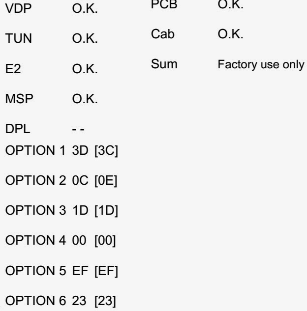
[If the CCU ports have been checked and found to be incorrect or
not located then " - - " will appear in place of "O.K.".]
ADJUSTMENT PROCEDURE

Additional information for Self-Check
feature
(Information in brackets {} refers to the TX-21MD4)
FACTORY SETTINGS
To return customer settings to factory settings and clear owner ID of all information input by the customer, enter Self-Check mode. Press the down (-/v) button on the customer controls at the front of the TV set, at the same time pressing the STATUS button on the remote control. To exit Self Check, switch off the TV set at the power button.
Self Check is also used to automatically check the bus lines and hexadecimal code of the TV set. If the CCU ports have been checked and found to be incorrect or not located then " - - " will appear in place of "O.K.". For more in-depth TV diagnostics use the LUCI interface as listed below.
Service Aids
To aid in the service of our current chassis there are a number of Service Aids which have been made available.
• LUCI interface kit (Linked Utility Computer Interface) Part number: TZS6EZ002.
This contains interface and cables for connecting TV service connector and a PC as well as diagnostic software. As new models are introduced upgrade software will become available.
• VICI (Visual Interactive Computer Information): These C.D.’s contain multimedia documentation providing quick access to service information. Part No. TZS7EZ006 & TZS7EZ005
• TASMIN (Technically Advanced System for Multimedia Interactive Notes). As well as providing a first step towards more interactive training this product also achieves quick access to Technical Information.

NOTE: Self Check should only be
used when refurbishing the TV set and not during normal repair work.
SMPS SCHEMATIC

CLICK ON THE PICTURES TO MAGNIFY
Universal Remote Control Set-up codes to check with Panasonic Brand Televisions.[CRT, LCD & Plasma types]
0016 0032 0033 0049 0054 0075
0099 0101 0104 0107 0110 0119 0143 0151 0152 0161 0166 0207 0249 0304 0305 0306
0396 0420 0461 0611 0631 0633 0692
No comments:
Post a Comment
The most important thing to remember about the Comment Rules is this:
The determination of whether any comment is in compliance is at the sole discretion of this blog’s owner.
Comments on this blog may be blocked or deleted at any time.
Fair people are getting fair reply. Spam and useless crap and filthy comments / scrapers / observations goes all directly to My Private HELL without even appearing in public !!!
The fact that a comment is permitted in no way constitutes an endorsement of any view expressed, fact alleged, or link provided in that comment by the administrator of this site.
This means that there may be a delay between the submission and the eventual appearance of your comment.
Requiring blog comments to obey well-defined rules does not infringe on the free speech of commenters.
Resisting the tide of post-modernity may be difficult, but I will attempt it anyway.
Your choice.........Live or DIE.
That indeed is where your liberty lies.
Note: Only a member of this blog may post a comment.