
NORDMENDE SPECTRA SK3 COLOR TP4330 CHASSIS F9
IC-TDA 3300 B
IC-TEA 1020 SP
IC-TDA 2541
IC-TDA 2593 OR
IC-TDA 2594
IC-LM 340 T-12
IC-uPC 7812 H, .
IC-SFC 2709 DC
IC-72709 P,
IC-TBA 120 T
IC-TDA 2006
TDA 3300 B can be replaced with TDA 3300, but TDA 3300 cannot replaced with TDA 3300.
TDA 2593 not interchangeable with TDA 2594
Right side
Supply with Step-Up line synchronized (Supply is 80 Volt converted to 135 Volt)
Synchronization
Line deflection output (Telefunken BU208) EHT + Tripler + E/W Correction.
- Left side
Signal Processing / Video with TDA3300 (MOTOROLA)
Frame deflection with TEA1020SP (Thomson)
Tuner + IF VIDEO AND SOUND BOARD
This chassis runs cold without particularly hot parts. It's higly reliable and durable.
It's power supplyed by a separation transformer (see picture) wich
provides all mains voltages for the set then these are converted where
needed by line synch SMPS stabilized switching circuitry to supply the
main parts of the receiver (Deflections and Video).
Probabily one of the best chassis made by NORDMENDE During the transition to THOMSON.
We can see a discrete level of integration here and we are in 1981 !!!!
you can find this Chassis even in some SABA Tellye.
This pictured here is made by NORDMENDE in THOMSON Transition (See code Style Numbers)
Fully transistorized chassis
Designation: Chassis F 9
Components
8 Integrated circuits
21 Transistors
1 Thyristor
45 Diodes
1 EHT rectifier (cascade)
Electrical values
Power supply 220/240 V ~
Consumption 85 W
EHT 25 kV
Antenna input: Sensitivity limits 40 uV
Input impedance 75 Ohm
Sound output: Output stage (rms) 7W
Loudspeaker impedance 8 Ohm


- VIDEO CHROMA PROCESSING WITH TDA3300 (MOTOROLA)

TDA3300 3301 TV COLOR PROCESSOR
This device will accept a PAL or NTSC composite video signal and output the
three color signals, needing only a simple driver amplifier to interface to the pic-
ture tube. The provision of high bandwidth on-screen display inputs makes it
suitable for text display, TV games, cameras, etc. The TDA3301 B has user con»
trol laws, and also a phase shift control which operates in PAL, as well as NTSC.
0 Automatic Black Level Setup
0 Beam Current Limiting
0 Uses Inexpensive 4.43 MHZ to 3.58 MHz Crystal
0 No Oscillator Adjustment Required
0 Three OSD Inputs Plus Fast Blanking Input
0 Four DC, High Impedance User Controls
0 lnterlaces with TDA33030B SECAM Adaptor
0 Single 12 V Supply
0 Low Dissipation, Typically 600 mW
The brilliance control operates by adding a pedestal to the output
signals. The amplitude of the pedestal is controlled by Pin 30.
During CRT beam current sampling a standard pedestal is
substituted, its value being equivalent tothe value given by V30 Nom
Brightness at black level with V30 Nom is given by the sum of three gun
currents at the sampling level, i.e. 3x20 |.1A with 100 k reference
resistors on Pins 16, 19, and 22.
During picture blanking the brilliance pedestal is zero; therefore, the
output voltage during blanking is always the minimum brilliance black
level (Note: Signal channels are also gain blanked).

Chrominance Decoder
The chrominance decoder section of the TDA3301 B
consists of the following blocks:
Phase-locked reference oscillator;
Phase-locked 90 degree servo loop;
U and V axis decoders
ACC detector and identification detector; .
Identification circuits and PAL bistable; .
Color difference filters and matrixes with fast blanking
Circuits.
The major design considerations apart from optimum
performance were:
o A minimum number of factory adjustments,
o A minimum number of external components,
0 Compatibility with SECAM adapter TDA3030B,
0 Low dissipation,
0 Use of a standard 4.433618 Mhz crystal rather
than a 2.0 fc crystal with a divider.
The crystal VCO is of the phase shift variety in which the
frequency is controlled by varying the phase of the feedback.
A great deal of care was taken to ensure that the oscillator loop
gain and the crystal loading impedance were held constant in
order to ensure that the circuit functions well with low grade
crystal (crystals having high magnitude spurious responses
can cause bad phase jitter). lt is also necessary to ensure that
the gain at third harmonic is low enough to ensure absence of
oscillation at this frequency.
It can be seen that the
necessary 1 45°C phase shift is obtained by variable addition
ol two currents I1 and I2 which are then fed into the load
resistance of the crystal tuned circuit R1. Feedback is taken
from the crystal load capacitance which gives a voltage of VF
lagging the crystal current by 90°.
The RC network in the T1 collector causes I1 to lag the
collector current of T1 by 45°.
For SECAM operation, the currents I1 and I2 are added
together in a fixed ratio giving a frequency close to nominal.
When decoding PAL there are two departures from normal
chroma reference regeneration practice:
a) The loop is locked to the burst entering from the PAL
delay line matrix U channel and hence there is no
alternating component. A small improvement in signal
noise ratio is gained but more important is that the loop
filter is not compromised by the 7.8 kHz component
normally required at this point for PAL identification
b) The H/2 switching of the oscillator phase is carried out
before the phase detector. This implies any error signal
from the phase detector is a signal at 7.8 kHz and not dc.
A commutator at the phase detector output also driven
from the PAL bistable coverts this ac signal to a dc prior
to the loop filter. The purpose ot this is that constant
offsets in the phase detector are converted by the
commutator to a signal at 7.8 kHz which is integrated to
zero and does not give a phase error.
When used for decoding NTSC the bistable is inhibited, and
slightly less accurate phasing is achieved; however, as a hue
control is used on NTSC this cannot be considered to be a
serious disadvantage.
90° Reference Generation
To generate the U axis reference a variable all-pass network
is utilized in a servo loop. The output of the all-pass network
is compared with the oscillator output with a phase detector of
which the output is filtered and corrects the operating point of
the variable all»pass network .

As with the reference loop the oscillator signal is taken after
the H/2 phase switch and a commutator inserted before the
filter so that constant phase detector errors are cancelled.
For SECAM operation the loop filter is grounded causing
near zero phase shift so that the two synchronous detectors
work in phase and not in quadralure.
The use of a 4.4 MHz oscillator and a servo loop to generate
the required 90° reference signal allows the use of a standard,
high volume, low cost crystal and gives an extremely accurate
90° which may be easily switched to 0° for decoding AM
SECAM generated by the TDA3030B adapter.
ACC and Identification Detectors
During burst gate time the output components of the U and
also the V demodulators are steered into PNP emitters. One
collector current of each PNP pair is mirrored and balanced
against its twin giving push-pull current sources for driving the
ACC and the identification filter capacitors.
The identification detector is given an internal offset by
making the NPN current mirror emitter resistors unequal. The
resistors are offset by 5% such that the identification detector
pulls up on its filter capacitor with zero signal.
Identification
See Figure 11 for definitions.
Monochrome I1 > I2
PAL ldent. OK I1 < lg
PAL ldent_ X l1 > I2
NTSC I3 > I2
Only for correctly identified PAL signal is the capacitor
voltage held low since I2 is then greater than I1.
For monochrome and incorrectly identified PAL signals l1>l2
hence voltage VC rises with each burst gate pulse.
When V,ef1 is exceeded by 0.7 V Latch 1 is made to conduct
which increases the rate of voltage rise on C. Maximum
current is limited by R1.
When Vref2 is exceeded by 0.7 V then Latch 2 is made to
conduct until C is completely discharged and the current drops
to a value insufficient to hold on Latch 2.
As Latch 2 turns on Latch 1 must turn off.
Latch 2 turning on gives extra trigger pulse to bistable to
correct identification.
The inhibit line on Latch 2 restricts its conduction to alternate
lines as controlled by the bistable. This function allows the
SECAM switching line to inhibit the bistable operation by firing
Latch 2 in the correct phase for SECAM. For NTSC, Latch 2
is fired by a current injected on Pin 6.
lf the voltage on C is greater than 1.4 V, then the saturation
is held down. Only for SECAM/NTSC with Latch 2 on, or
correctly identified PAL, can the saturation control be
anywhere but minimum.
NTSC Switch
NTSC operation is selected when current (I3) is injected into
Pin 6. On the TDA33O1 B this current must be derived
externally by connecting Pin 6 to +12 V via a 27 k resistor (as
on TDA33OOB). For normal PAL operation Pin 40 should be
connected to +12 V and Pin 6 to the filter capacitor.
4 Color Difference Matrixing, Color Killing,
and Chroma Blanking
During picture time the two demodulators feed simple RC
filters with emitter follower outputs. Color killing and blanking
is performed by lifting these outputs to a voltage above the
maximum value that the color difference signal could supply.
The color difference matrixing is performed by two
differential amplifiers, each with one side split to give the
correct values of the -(B-Y) and -(Ft-Y) signals. These are
added to give the (G-Y) signal.
The three color difference signals are then taken to the
virtual grounds of the video output stages together with
luminance signal.
Sandcastle Selection
The TDA3301B may be used with a two level sandcastle
and a separate frame pulse to Pin 28, or with only a three level
(super) sandcastle. In the latter case, a resistor of 1.0 MQ is
necessary from + 12 V to Pin 28 and a 70 pF capacitor from
Pin 28 to ground.
Timing Counter for Sample Control
In order to control beam current sampling at the beginning
of each frame scan, two edge triggered flip-flops are used.
The output K ofthe first flip-flop A is used to clock the second
tlip-flop B. Clocking of A by the burst gate is inhibited by a count
of A.B.
The count sequence can only be initiated by the trailing
edge of the frame pulse. ln order to provide control signals for:
Luma/Chroma blanking
Beam current sampling
On-screen display blanking
Brilliance control
The appropriate flip-flop outputs ar matrixed with sandcastle
and frame signals by an emitter-follower matrix.
Video Output Sections
Each video output stage consists of a feedback amplifier in A further drive current is used to control the DC operating
which the input signal is a current drive to the virtual earth from point; this is derived from the sample and hold stage which
the luminance, color difference and on-screen display stages. samples the beam current after frame flyback.
 BU208(A)
Silicon NPN
npn transistors,pnp transistors,transistors
Category: NPN Transistor, Transistor
MHz: <1 MHz
Amps: 5A
Volts: 1500V
HIGH VOLTAGE CAPABILITY
JEDEC TO-3 METAL CASE.
DESCRIPTION
The BU208A, BU508A and BU508AFI are
manufactured using Multiepitaxial Mesa
technology for cost-effective high performance
and use a Hollow Emitter structure to enhance
switching speeds.
APPLICATIONS:
* HORIZONTAL DEFLECTION FOR COLOUR TV With 110° or even 90° degree of deflection angle.
ABSOLUTE MAXIMUM RATINGS
Symbol Parameter Value Unit
VCES Collector-Emit ter Voltage (VBE = 0) 1500 V
VCEO Collector-Emit ter Voltage (IB = 0) 700 V
VEBO Emitter-Base Voltage (IC = 0) 10 V
IC Collector Current 8 A
ICM Collector Peak Current (tp < 5 ms) 15 A
TO - 3 TO - 218 ISOWATT218
Ptot Total Dissipation at Tc = 25 oC 150 125 50 W
Tstg Storage Temperature -65 to 175 -65 to 150 -65 to 150 oC
Tj Max. Operating Junction Temperature 175 150 150 °C
DESCRIPTION
The TDA2591 is a circuit intended for the horizontal
deflection of color TVsets, supplied with transistors
or SCR’S.
The TDA2591 and TDA2593 are integrated line
oscillator ‘_circuits for colour television receivers using
thyristor or transistor line deflection output stages.
The _circuits incorporate a line oscillator ‘which is
based on the threshold switching principle, a line de-
flection output stage capable of direct drive of thyristor
deflection circuits, phase comparison between the
oscillator voltage and both the sync pulse and line
flyback pulse. Also included on the chip is a switch for
changing the filter characteristic and the gate circuit
when used for VCR.
The TDA2593 generates a sandcastle pulse (at pin
7) suitable for use with the TDA.2532.
.LINE OSCILLATOR(two levels switching)
.PHASE COMPARISON BETWEEN SYNCHRO-
PULSE AND OSCILLATOR VOLTAGE Ø 1, ENABLED BY AN INTERNAL PULSE,
(better parasitic immunity)
PHASE COMPARISON BETWEEN THE FLYBACK
PULSES AND THE OSCILLATOR VOLTAGE Ø2
.COINCIDENCE DETECTOR PROVIDING A LARGE HOLD-IN-RANGE.
.FILTER CHARACTERISTICS AND GATE SWITCHING FOR VIDEO RECORDER APPLICATION.
.NOISE GATED SYNCHRO SEPARATOR
.FRAME PULSE SEPARATOR .BLANKING AND SAND CASTLE OUTPUT PULSES
.HORIZONTAL POWER STAGE PHASE LAGGING CIRCUIT
.SWITCHING OF CONTROL OUTPUT PULSE WIDTH
.SEPARATED SUPPLY VOLTAGE OUTPUT STAGE ALLOWING DIRECT DRIVE OF SCR’S CIRCUIT
.SECURITY CIRCUIT MAKES THE OUTPUT PULSE SUPPRESSED WHEN LOW SUPPLY
VOLTAGE.
Function description power supply
The power supply unit utilized here works on the “Step-up” principle, that is the input voltage on test point 3= 80 Vis smaller than the stabilized output voltage U 1 = 135 V. The stabilization operates line synchronized as a switched mode power unit. Mains separation is obtained over a low radiation transformer. The input voltages possible are 220 V and 240 V. The mains transformer has two separate secondary windings which after rectification provide U 3 = approx. 24 V for the power supply of the sound stage and approx. 80 V to supply the remaining circuits.
 Operation of the switching mode
The switching transistor TP 30 is made periodically conducting with the forward trace voltage from pin 2 of the line transformer being applied to the base via DP 33/RP 37/ CP 36/RP 36. The charging inductance LP 30 is thereby charged up. The input voltage of approx. 80 V drives a rising current with a sawtooth waveform through the charging inductance and the switching transistor RP 31 to earth. The relationship between input voltage and charging inductance is so arranged that the sawtooth current reaches 5A after approx. 25 us. The voltage drop on RP 31 is then so large (1,1 V) that thyristor DP 34 is made to conduct by the voltage being applied to the gate via DP 32 and RP 32. Subsequently through this the base current for the switching transistor TP 30 is interrupt- ed. The combination of CP 36/RP 36 maintains the correct switch-off conditions. For the remainder of the forward trace time the thyristor remains in the conducting state. On- ly at the start of the retrace when the thyristor is negatively poled over RP 33is it shut off. At the start of the subsequent forward trace, TP 30 is switched again and the previously described cycle is repeated. During the time that DP 34 is conducting, the charging inductance can discharge over DP 30. Charging capacitor CP 33 which is al- ready charged to 80 V over the galvanic connection is thus charged further. After a few periods the voltage U 1 = 135 V is attained. If the charging process in LP 30 is not now prematurely ended, then the output voltage, depending on the load, can rise above the desired stabilized voltage U 1 (135 V).
Operation of the regulationIn the regulated condition, the firing point of thyristor DP 34 is advanced depending on load and input voltage. This is achieved by adding a regulation voltage dependent DC voltage over RP 41, to the sawtooth voltage on the gate obtained from RP 32. This regulation voltage dependent DC voltage is obtained by comparing the voltage to be stabilized U 1 = 185 V - (reduced over RP 49, RP 50 and PP 30) - with a stable reference (over RP 46 to U2=+ 12 V) from the operational amplifier IP 30. U 1 is adjusted to + 135 V (+1 V) with PP 30. The adjustment must be carried out with a dark picture screen because the reference voltage is additionally influenced from a beam current dependent component over RP 51. Through the reduction of U 1 by approx. 2 V the picture format is held constant.
 Protection circuit
Should a fault occur in the regulation components PP 30, RP 49, RR 41 or IP 30 which causes U 1 to become unregulated and rise above 135 V, then all other voltages which are obtained from the line transformer will also rise. The voltage on U 7 (+ 30 V) which additionally provides the supply for IP 30 will also increase. However as soon as a voltage of 34 - 35 Vis attained, thyristor DP 34 triggers over DP 39 and RP 39. A further in- crease of voltage is thus limited. Switch-on and starting phase As previously described, the line pulse on pin 2 of the line transformer is necessary for the operation of the power supply unit. The function sequence when initially switching on is thus fixed. Firstly the stages IP 30 and TL 01 receive the operating voltage U 3 = 24 V over diode DP 38 in order that they may start. The horizontal generator IL 01 receives it’s operating voltage over RP 47 and CP 47 at the moment of switching on. This voltage however sinks as the charge on CP 47 rises. IL 01 can already work with this operating voltage and therewith also the horizontal deflection with the at first reduced input voltage U1 ~ 80 V=. The power supply begins to operate as already described and all voltages take up their nominal values. The U 3 supply (24 V) is now less than the voltage standing on pin 2 of the line transformer (30 V cathode of DL 01). This voltage blocks DP 38 thus preventing the sound section from influencing the display on the screen.
Notes to repair workGeneral
The description shows that the dependence of the power unit controls the operation of the protection circuit. If U 1 is too small, then it is practically certain that there is either a short circuit or an open circuit in the signal flow from the horizontal generator to the line output stage or in the power supply over pin 2 of the line transformer. Starting aid (only for use in cases of repair): To enable the horizontal oscillator to commence oscillating, a 68 2/4 W wire wound resistor is to be connected from the anode of DP 38 to the cathode of DL 10. The line generator thus receives a voltage of approx. 7 -8V over IL 02 and DL 11. Fault in the switched mode power unit Disconnect the collector connection of TP 30. This will enable the regulation of IP 30 and the function of thyristor DP 34 to be checked. 4. Function check of IP 30: Connect an oscilloscope or multimeter to pin 6 of the IP 30. The voltage is < + 2,5 V. When the reference voltage on pin 2 of the IP 30 is short circuited to earth (pin 4) then the output voltage on pin 6 should rise to approx 20 V. 2. Function check of DP 34: Connect an oscilloscope to the anode of DP 34 and check oscilloscope 1. Now short circuit the reference voltage of IP 30 (pin 2) to earth (pin 4) and check oscilloscope 2.
NORDMENDE SPECTRA SK3-COLOR T3137 CHASSIS F9 (492.445) Switching regulator
power supply device combined with the horizontal deflection circuit of a
television receiver which it supplies
Step-up
switching regulator power supply device comprising, connected between
the poles of a rectifier circuit supplied by an isolating voltage
step-down transformer and loaded by a first filter capacitor, and
inductance and the collector-emitter path of a first switching
transistor of NPN type, a first diode whose anode is connected to the
junction of the inductance and to the collector of said transistor and
whose cathode is connected to a second filter and storage capacitor
supplying a voltage at its output which supplies a horizontal deflection
circuit of a television receiver.

This horizontal deflection
circuit which comprises in cascade a horizontal oscillator, a driver
stage and an output stage, forms an integral part of the circuit
controlling said first transistor and determines the repetition period
of the switching, because it is started under an initial voltage
slightly less than the unregulated input voltage of the device.
The
switching transistor is being turned off in synchronism with the
turning off of the trace switch transistor by using flyback pulses of
negative polarity to bias the base thereof.

1.
A power supply device with switching regulation and boosting of its DC
output voltage, combined with a horizontal deflection circuit of a
television receiver, supplied thereby and which comprises in cascade a
horizontal oscillator, a driver stage and an output stage including a
trace switch transistor and a line transformer, this device comprising
an inductance and the collector-emitter path of a switching transistor
connected in series between the poles of a DC input voltage source, a
rectifying diode connected by its anode to the junction between the
inductance and the collector of said switching transistor and by its
cathode to one of the terminals of a filtering and storage capacitor
whose other terminal is connected to the emitter of said transistor, so
as to apply across its terminals an initial DC voltage slightly lower
than said input voltage, when said switching transistor is turned off,
and a regulated DC output voltage with a level higher than said input
voltage, when said transistor is recurrently, alternately turned on and
off, the level of said output voltage depending on the duty cycle of
said switching transistor states, and a control circuit feeding the base
of said switching transistor and including a regulator stage comparing
an adjustable fraction of said output voltage to a fixed reference
voltage and supplying a regulating current or voltage proportional to
the difference between said compared voltages, a pulse-width modulator
triggered by means of a recurrent signal and supplying a rectangular
signal whose duty cycle varies as a function of said regulating current
or voltage, another driver stage receiving the rectangular signal and
controlling said switching transistor, the regulation and boosting of
said output voltage being controlled by the initially independent
starting up of the entire horizontal deflection circuit when supplied by
said initial voltage from said power supply device as soon as a DC
input voltage is applied thereto and which then delivers recurrent
trigger pulses to said pulse-width modulator, one of the supply inputs
of said other driver stage receiving directly a first voltage waveform
whose positive alternations comprise constant-voltage plateau and whose
negative alternations comprise negative-going horizontal flyback pulses
provided by a first secondary winding of said line transformer, so as
to control the turning off of said switching transistor substantially
simultaneously with that of the trace switch transistor.

2.
A power supply device as claimed in claim 1, wherein said other driver
circuit comprises a third transistor whose emitter is connected to the
base of said switching transistor and which is of the same type as the
latter, whose collector is connected, through said supply input, to
said first secondary winding of said line transformer to receive
therefrom said first waveform and whose base is coupled to the output
of said pulse-width modulator.
3. A power supply
device as claimed in claim 2, wherein the collector of said third
transistor is connected, through a resistor to the supply input and its
emitter is connected, furthermore, to that of the switching transistor
through another resistor so that the negative-going flyback pulses,
applied to the collector of said third transistor, control the
symmetric (reverse) saturation thereof so as to reversely bias the
base-emitter junction of said switching transistor.
4.
A power supply device as claimed in claim 2, wherein the collector of
said third transistor is connected to said power supply input through a
fourth diode conducting in the normal direction of its
collector-emitter path, and wherein its emitter is further connected,
on the one hand, through a resistor, to the emitter of the switching
transistor and, on the other hand, through another resistor and a fifth
diode conducting in the reverse direction to that of the base-emitter
junction of the switching transistor, so as to transmit to the base
thereof negative-going flyback pulses through a voltage divider formed
by said two resistors in series.

5.
A power supply device as claimed in claim 1, wherein said other driver
circuit comprises a third transistor whose emitter is connected to the
base of said switching transistor, whose collector is connected to
that of this latter so as to form a so-called Darlington circuit and
whose base coupled, moreover, to said pulse-width modulator is further
connected, through a resistor and a diode in series, to said first
secondary winding of said line transformer so as to control the
simultaneous turn off of both transistors of said Darlington circuit by
simultaneously reversely biasing their respective base-emitter
junctions, connected in series, by means of negative-going flyback
pulses.

6.
A power supply device as claimed in any one of the preceding claims,
wherein said pulse-width modulator, supplied at its input with a
voltage waveform whose positive alternations comprise positive-going
flyback pulses and whose negative alternations comprise constant
negative-voltage plateaux, comprises a passive circuit which forms a
simple integrator during positive alternations because one of its
resistors is shunted by a diode and which is a cascaded double
integrator during negative alternations of this waveform so as to
deliver during the trace periods of the scan a linearly decreasing
negative current which, added to the positive regulating current,
supplies the base of a fourth comparator transistor, so that the turning
off of this latter through equality of the negative and positive
currents supplied to this base controls the beginnings of the saturation
of said switching transistor in such a manner that the duration of
this saturation varies inversely with variation of said output voltage.
7.
A power supply device as claimed in claim 6, wherein said comparator
transistor is biased, furthermore, at its base by means of a resistor
which connects it to the positive pole of said input voltage source, so
that it remains saturated in the absence of flyback pulses supplied by
said horizontal deflection circuit so as to maintain the switching
transistor in a cut off state.
8. A power supply device
as claimed in any one of the preceding claims, wherein said control
circuit, except for the regulator stage which is supplied by said output
voltage, is supplied by said input voltage.
9. A
power supply device as claimed in any one of the preceding claims 1 to
6, wherein said DC supply voltage of said control circuit, with the
exception of one of the inputs of said regulator stage receiving said
output voltage, is supplied by a secondary winding of said line
transformer, through a rectifier circuit including a diode and a
filtering capacitor.
Description:
BACKGROUND OF THE INVENTION
The
present invention relates to a switching voltage regulator power
supply device combined with the horizontal deflection circuit of a
television receiver which it supplies with DC voltage. It relates, more
particularly, to DC voltage supply devices of the type which boost or
increase the voltage supplied at the output of the device in relation
to the level of a DC voltage applied to its input and which regulate
this level by recurrent switching of this input voltage, this switching
being synchronous with the (horizontal) line frequency of the
television receiver supplied by this device.

Switched step-up or
boost voltage regulator devices of this type are known, particularly
from the publications U.S. Pat. Nos. 3,571,697 (or 3,736,496) and they
are related to switched mode power supply devices or DC-DC converters
of the so-called unisolated flyback type, in which the
collector-emitter path of a bipolar switching transistor is connected
in series with a commutating inductance between the terminals of a DC
source supplying an input voltage and a rectifying diode is connected
between the junction of the inductance with the transistor and one of
the plates of a filtering or storage capacitor (in parallel with the
load), so that the current stored in the inductance during the
conducting period of the transistor is used for charging the capacitor
(and supplying the load) through the diode during its consecutive
cut-off period. The use of a switched-mode power supply device of this
type in television receivers for supplying, particularly, the
horizontal deflection circuit thereof has been described, for example,
in two articles by VAN SCHAIK entitled respectively "AN INTRODUCTION TO
SWITCHED-MODE POWER SUPPLIES IN TV RECEIVERS" and "CONTROL CIRCUITS
FOR SMPS IN TV RECEIVERS," appearing respectively on pages 93 to 108 of
No. 3, Vol. 34, of September 1976 and on pages 162 to 180 of No. 4 of
this same volume, of December 1976, in the English language Dutch
review "ELECTRONIC APPLICATIONS BULLETIN" of PHILIPS', or on pages 181
to 195 of No. 135 of July 1977 and on pages 210 to 226 of No. 136 of
October 1977 of the British review "MULLARD TECHNICAL COMMUNICATIONS."
Since none of the switched-mode power supply devices described in these
articles, isolated or not from the mains, whether they use a forward
or a flyback converter, supplies at its output a DC voltage for
supplying the horizontal deflection circuit before the switching
transistor has been turned on (saturated or conducting) one or more
times, the control circuit of this transistor must comprise an
independent relaxation oscillator and must be supplied by the same DC
input voltage (rectified and smoothed voltage of the AC mains) as the
switching circuit comprising the inductance and the transistor in
series. Synchronization of the switching with the horizontal deflection
can only occur subsequently, when the horizontal oscillator and/or the
horizontal deflection circuit as a whole have begun to operate, as
soon as the supply voltage supplied thereto by the device which
operates independently on starting up, has become sufficient. This
synchronization of the switching with the horizontal deflection,
advantageous for reducing or eliminating the interferences visible on
the screen which are caused by high-frequency energy radiation due to
abrupt transitions of power switching, particularly when the switching
transistor is being cutt off, is generally carried out by means of a
signal comprising flyback or retrace pulses, taken at the terminals of
an auxiliary secondary winding of the line tranformer whose primary
winding is generally connected between the output of the switched-mode
power supply device and one of the terminals of the trace switch which
is provided in the output stage. It is also possible to use for this
purpose the signal provided by the horizontal oscillator (see, for
example, the publication FR-A-2 040 217).
In
a switched-mode supply for a television receiver described in the
publication FR-A-2 261 670, the circuit for controlling the switching
transistor of a forward-type converter, supplied with the rectified and
smoothed voltage of the mains, comprises a bistable trigger circuit of
flip-flop one of whose outputs is coupled back to one of its trigger
inputs through a regulating circuit comprising a sawtooth voltage
generator and a voltage comparator providing transitions which control
the setting of the flip-flop, when the sawtooth voltage reaches the
level of a voltage proportional to the amplitude of the flyback pulse.
The other one of the two complementary outputs of this flip-flop is
coupled back to its other trigger input through a so-called starting
loop comprising an ascending voltage wave-form which approaches
asymptotically a predetermined voltage level smaller than a
predetermined fraction of the nominal level which the amplitude of the
flyback pulse must reach in normal operation, and a voltage comparator
providing transitions which control the recurrent resetting of the
flip-flop to its initial state until the flyback pulse has reached or
exceeded a threshold amplitude slightly below its nominal amplitude.
When this threshold amplitude has been exceeded, resetting of the
flip-flop is controlled by the flyback pulses themselves, negative-going
in the present case, which supplant the starting pulses. Such an
arrangement is equivalent to an astable multivibrator during the
starting period, which later becomes a monostable one and triggered by
the flyback pulses and whose quasi-stable state has a variable duration,
depending on the amplitude of these pulses so as to obtain regulation
thereof by the duty cycle. The pulse which controls the closing of the
switch (saturation of the switching transistor) begins here with the
leading edge of the flyback pulse and its duration or length is
modulated as a function of the current drawn by the load and of the
variation of the rectified and smoothed voltage, so that its end
controlling the opening of the supply switch (cutting off the
transistor) occurs during the trace portion of the horizontal
deflection. Thus it can be seen that this switched-mode supply, like
most of the known ones, effects regulation of its output voltage by
varying the duty cycle as a reverse function of the level thereof.
Since
the high-frequency radiation is precisely at its most intense during
abrupt transitions of current in the switching inductance and of the
voltage accross its terminals, the appearance of one or more vertical
lines (light or dark according to the sense of the modulation of the
carrier wave by the video signal) may be observed, contrasting with the
normal contents of the picture, whose location on the screen depends on
the duration of the pulse controlling the switching transistor. The
effect of this radiation becomes particularly troublesome when the input
signal of the radio-frequency stages or tuner is small, particularly
when the selected channel is situated in the lower part of the VHF band,
for the automatic gain-control device of the receiver acts on the gain
of the high-frequency and/or intermediate-frequency input stages, so
that the sensitivity (amplification) of the receiver is then maximum and
this also as concerns the spurious radiated signals.
SUMMARY OF THE INVENTION
The
present invention, on the one hand, avoids or at least appreciably
reduces the interferences visible on the screen by controlling the
cutting off of the switching transistor in synchronism with the leading
edge or the flyback pulse and, on the other hand, the starting of the
horizontal deflection circuit by means of a simple circuit without any
special oscillator, and provides efficient protection of the switching
transistor which remains cut off when the horizontal deflection circuit
is not operating. This is made possible by using a step-up switching
regulator supply device of the type described in the publication U.S.
Pat. No. 3,571,697 and whose control circuit includes, in accordance
with the invention, the horizontal deflection circuit, which it
supplies.
The object of the present invention is a power supply
device with boosting and regulation of its output voltage by switching,
combined with a horizontal sweep circuit of a television receiver,
which it supplies and which comprises a horizontal oscillator, a driver
stage and an output stage including a line transformer, this device
comprising an inductance and the collector-emitter path of a switching
transistor connected in series between the poles of a DC input voltage
source, a rectifiying diode connected by its anode to the junction
between the inductance and the collector of the transistor and by its
cathode to one of the terminals of a filtering capacitor whose other
terminal is connected to the emitter of the transistor so as to supply
between its terminals an initial output voltage, slightly lower than the
input voltage, when the transistor is cut off permanently, and a
regulated DC output voltage with a level higher than the input voltage,
when the transistor is recurrently alternately turned on and off, the
level of this output voltage depending on the duty cycle of the
respective states of this transistor, and a control circuit for driving
the base of the transistor and including a regulator stage comparing an
adjustable fraction of the output voltage to a fixed reference voltage
and supplying a regulating current or voltage proportional to the
difference between these compared voltages, to a pulse-width modulator
triggered by means a recurrent signal and supplying a rectangular signal
whose duty cycle varies as a function of this regulating current or
voltage, and another driver stage receiving the rectangular signal and
controlling the switching transistor.
In
accordance with the invention, the horizontal deflection forming an
integral part of the circuit controlling the switching transistor,
determines therefor, from the start, the repetition period of the
rectangular signal controlling it, and one of the supply inputs of the
other driver stage receives directly a first voltage waveform whose
positive alternations, comprise DC voltage plateaux and whose negative
alternations comprise negative-going flyback pulses supplied by a first
secondary winding of the line transformer, so as to control the
cut-off the switching transistor substantially simultaneously with that
of the trace switch transistor.
DESCRIPTION OF THE DRAWINGS
The
invention will be better understood and other of its objects,
characteristics, features and advantages will become clear from the
following description and the accompanying drawings which refer thereto,
given solely by way of example, in which:
FIG. 1 is partly a
block diagram and partly a schematic diagram of a power supply device
combined with the horizontal deflection circuit in accordance with the
invention;
FIG. 2 shows waveforms of two voltages and of a current at different points of the circuit of FIG. 1;
FIG. 3 is a block diagram of the circuit for controlling the switching transistor;
FIGS.
4 and 5 are schematic diagrams of two different embodiments of the
driver circuit 20 forming the output stage of the control circuit of
FIG. 3;
FIG. 6 is the block diagram of one embodiment of the pulse-width modulator 10 of the circuit of FIG. 3;
FIG. 7 shows three voltage waveforms at different points of the circuit of FIG. 6;
FIG.
8 is a schematic diagram of one embodiment of the pulse-width
modulator 10 of the circuit of FIG. 3, using discrete components;
FIG. 9 shows a current waveform and two voltage waveforms at different points of the circuit of FIG. 8;
FIG.
10 is a schematic diagram of a conventional embodiment of a regulator
stage 30 adapted to supply the modulation input of the modulator of
FIG. 8; and
FIGS. 11 and 12 are partial respective schematic
diagrams of two embodiments of a power supply device in accordance with
the invention.
DESCRIPTION OF THE PREFERRED EMBODIMENTS
FIG.
1 shows the schematic diagram of the power stages of the power supply
device and of the horizontal deflection circuit of the television
receiver, which it supplies and in block diagram form the respective
circuits which control them.
The DC input voltage VE which is
not regulated is supplied by a rectifier bridge R with four diodes,
supplied at its input by the secondary winding of an insulating
step-down transformer TS, whose primary winding is supplied by the AC
mains. The output terminals of rectifier bridge R are connected
respectively to the terminals of a first filtering capacitor C1 across
which this input voltage VE is taken.
The positive pole P of
this source of the input voltage VE is connected to one of the terminals
of an energy-storage inductance L, whereas its negative pole N is
connected to ground G of the receiver, which is isolated from the mains.
The other terminal of inductance L is connected, on the one hand, to
the collector of a first NPN bipolar switching transistor T1, whose
emitter is connected to ground G and, on the other hand, to the anode of
a first diode D1 whose cathode is connected to the positive terminal
of a second filtering and storage capacitor C2. With the negative
terminal of this second capacitor C2 connected to ground G, the output
voltage VS which supplies the load is taken between its terminals.
Such
a supply device BS provides both step-up or boost and regulation of
its output voltage level, because the first switching transistor T1 and
the first diode D1 thereof are connected so as to conduct respectively
currents flowing through inductance L in the same direction, it
supplies at its output formed by the terminals of the second capacitor
C2, an initial DC voltage VSI as soon as the primary winding of the
insulating transformer TS is connected to the mains. This initial
voltage VSI which is equal to the input voltage VE less the forward
voltage drop VD1 across the first diode D1, is then supplied to the
load until the control circuit SC is started up, whose output 6 is
connected to the base of the first transistor T1 so as to cause it to
be alternately turned on and off.
When the first transistor T1
is turned on by positively biasing its base-emitter junction, its
collector-emitter path connects the junction of the inductance L with
the anode of the first diode D1 to ground G. Diode D1 being then
reversely biased, it ceases to conduct and the inductance L connected
by the first transistor T1 between the positive P and negative N poles
of the source supplying the unregulated DC input voltage VE, then
conducts a linearly increasing current IL so as to store the energy
which increases with the square of the conduction duration of the first
transistor T1, until this latter is cut off. At the instant when the
first transistor T1 is cut off after the control circuit SC has brought
its base-emitter voltage to zero or below, the voltage at the
terminals of inductance L is reversed so that, at its junction with the
collector of transistor T1 and the anode of diode D1, there appears a
voltage VM greater than the input voltage VE, which results in the
forward biasing of diode D1. Consequently, from the instant when
transistor T1 is cut off, diode D1 conducts a linearly decreasing
current until the energy stored in the form of a current IL in the
inductance L, which charges the second capacitor C2 to an output
voltage VS greater than the input voltage VE, disappears. The regulation
of the level of the output voltage VS is here effected in a
conventional way, by varying the duty cycle, i.e. the radio (quotient)
between the duration of the conducting period of transistor T1 and the
sum of the respective durations of two of its successive conducting and
cut off periods, as a function of the desired output voltage VS
(determined by comparison to a stable reference voltage).

According
to the invention, a supply device BS of the above-described type is
combined with the horizontal deflection circuit SH of a television
receiver, which it supplies, so that this latter forms an integral part
of its control circuit SC and for determining the repetition period of
its operation and so that the above-mentioned regulation by varying the
duty cycle maintains a stable peak-to-peak amplitude of the sawtooth
scanning current and/or the very high voltage for biasing the electrodes
(anode, focusing electrode and accelerating grid) of the cathode-ray
tube, which are obtained by rectifying the horizontal flyback pulses
supplied by a step-up secondary winding (not shown) of the line
transformer TL.
The horizontal deflection circuit SH which
comprises in cascade the horizontal oscillator OH whose known phase
control circuit with respect to the horizontal sync signal separated
from the composite video signal has not been shown here, the driver
stage HD controlled by the horizontal oscillator OH and controlling the
output stage OS of the horizontal deflection, is as a whole supplied by
the above-described regulated power supply device BS. In fact, the
positive supply input AL of the horizontal deflection circuit SH is
connected by means of a fuse FS to the junction of the cathode of the
first diode D1 with the positive terminal of the second capacitor C2,
which forms the positive output terminal SP of the regulated power
supply device BS. This supply input AL is connected directly to that of
the driver circuit HD and, preferably, through a conventional Zener
diode or series ballast transistor voltage regulator VR, to that of the
horizontal oscillator OH, which are moreover connected to the isolated
ground G.
The supply input AL of the horizontal deflection
circuit SH is furthermore connected to one of the primary winding
terminals B1 of the line transformer TL, whose other terminal AB is
connected in parallel to the collector of another switching transistor
TH, of NPN type, called trace switch transistor, to the cathode of a
second so-called shunt recovery diode DR, to one of the terminals of
another capacitor CR, called line-retrace capacitor, and to one of the
plates of an additional capacitor CS, called trace capacitor, which
supplies the horizontal deflection coils LH one terminal of which is
connected to its other terminal during the trace periods of the
scanning. The emitter of the scanning transistor TH, the anode of the
"shunt" recovery diode DR, the other terminal of the retrace capacitor
CR and the other terminal of the horizontal deflection coils LH are all
connected to ground G. This assembly of components thus connected forms
the output stage OS whose operation is well-known and does not form
part of the invention.
As
was mentioned above, as soon as the primary winding of the step-down
isolating transformer TS is connected to the mains, rectifier R
supplies the first filtering capacitor C1 so as to provide between its
terminals P and N a unregulated low DC voltage VE. With the first
transistor T1 then turned off, this input voltage is applied through
the inductance L and the first diode D1 to the second capacitor C2 so
as to obtain between the terminal SP and ground G an initial output
voltage VSI substantially equal to VE-VD1, which is approximately equal
to 60 percent of the regulated output voltage VS. This initial output
voltage VSI (equal to about 0.6 VS) is sufficient to cause the
generation of autonomous oscillations by the horizontal oscillator OH.
This latter supplies at its output, connected to the input of driver
circuit HD, pulses at an independent frequency close to the line
frequency. In response to these pulses, driver circuit HD, also
supplied by device BS, provides at the base of the trace switch
transistor TH pulses controlling its periodical cut off at this
independent frequency and its consecutive turning on after a period
greater than the duration of the flyback period, so that the recovery
diode DR may take the current from the deflector LH during substantially
the first half of the trace portion of the scan. During flyback or
retrace, with both transistor TH and diode DR cut off, the energy stored
in the form of currents respectively in the inductances of deflector
LH and of the primary winding B1 of the line transformer TL which are
then, from the AC current point of view, connected in parallel, flow in
an oscillating manner through the retrace capacitor CR which forms
therewith a parallel resonant circuit whose resonance period determines
the duration of the flyback period.
There then appears
periodically between point AB and ground G a voltage pulse VTH having
substantially a sinusoidal half-wave form, which is shown in Diagram A
of FIG. 2. The average value of this voltage VTH being then equal to
VSI, at start-up, and to VS, during established operation. The line
transformer TL comprises, in addition to a very-high-voltage winding and
other windings for supplying rectifying circuits, not shown, two
secondary windings B2, B3 respectively supplying across their terminals,
voltage waveforms comprising flyback pulses with zero average values
and with respectively negative and positive polarities.
This
means that the first secondary winding B2 supplies a voltage waveform
-VTL which, between two successive flyback pulses, comprises a positive
plateau whose level is equal to the average value of these pulses and
which is used, in accordance with the invention, to control the turn off
of the first transistor T1 so that the interferences which would
otherwise be visible only occur during the line-blanking periods
comprising the line-retrace periods. The second secondary winding B3
then supplies a voltage waveform +VTL which is the reverse of or
complementary to the preceding one -VTL.
One of the terminals of
each of these secondary windings B2, B3 is connected to ground G,
whereas their other terminals are respectively connected to two inputs 2
and 1 of the control circuit SC. A third input 3 of this latter is
connected to the SP output of the supply device BS and a fourth input 4
is connected to the positive pole P of the input voltage source VE. A
fifth terminal 5 of the control circuit SC is connected to ground G (or
negative pole N) and its output 6 is connected to the base of the first
transistor T1. This control circuit SC causes, following the start up
of the horizontal deflection circuit SH, a first saturation of the
first transistor T1 at a time determined by a pulse-width modulator
operating by conventional comparison of a sawtooth voltage waveform the
elaboration of which is controlled by a first flyback pulse, with a
regulating voltage, depending on the output voltage VS. During this
saturation period of transistor T1 which extends as far as the leading
edge of the next flyback pulse, energy is stored in inductance L.
From
the instant when transistor T1 is turned off, diode D1 transfers this
stored energy to the second capacitor C2, at the terminals of which it
causes an increase of the voltage VS with respect to its initial value
VSI, until the current in diode D1 is canceled out, when it becomes
reverse biased.
The collector-emitter voltage waveforms VTH of
the trace switch transistor TH and VCE of the switching transistor T1 in
established operation have been shown respectively by the diagrams A
and B of FIG. 2. Diagram C of FIG. 2 shows the corresponding waveform of
the current IL flowing through the inductance L.

When the base
of the first transistor T1 receives from the output 6 of the control
circuit SC a rectangular signal which turns it on at time instant t1,
its collector-emitter voltage VCE (Diagram B) becomes close to zero (V
CEsat )
and a linearly increasing current IL (Diagram C) flows through
inductance L from time t1 until time t2 when transistor T1 is again
turned off, which is controlled by the leading edge of the flyback pulse
VTH (Diagram A). With the collector current of transistor T1 canceled
at the end of the storage time of the excess minority carriers in the
base, the voltage across the terminals of the inductance L inverses its
polarity so as to be added to the input voltage VE, so that the
collector-emitter voltage VCE (Diagram B) then reaches a level VM
greater than VS (as well as VE), so as to apply forward bias to the
first diode D1, which then conducts the current IL through the
inductance L. This current IL, from time instant t2 when it reaches its
maximum value IM, becomes linearly decreasing and it flows through the
first diode D1 in the passing direction in order to recharge the second
capacitor C2 and supply, in particular, the horizontal deflection
circuit SH.
When the current IL passing through the first diode
D1 is canceled out at time t3, the collector-emitter voltage VCE of the
first transistor T1 becomes equal to the unregulated input voltage VE
until the next turn on of the transistor T1, and the first diode D1
remains reversely biased until the time when this latter is cut off
again.
From the above it can be easily seen that the principal
advantage of this combined device resides in the fact that a single
oscillator OH belonging to the horizontal deflection circuit SH is
sufficient for controlling the two power switching transistors TH and
T1.
Furthermore, a possible overload in the circuitry of the
television receiver, such for example as a short-circuit of the trace
switch transistor TH, results in overloading the diode D and the
inductance L. The first transistor T1 which is consequently cut off is
not subjected to this overload and is therefore protected. In order to
protect the rest of the television receiver as well as inductance L and
the first diode D1, a fuse FS may be connected in series in the supply
line from the second capacitor C2. This fuse FS may also be inserted
between pole P and inductance L.
It
is moreover known that it is difficult to construct switched supplies
for obtaining correct operation when it is not fully charged (for
supplying, for example, a ready-state remote-control receiver). In the
present case, the problem does not come up since, when the supply is in
operation, there is always a minimum load formed by the horizontal
deflection circuit. When this circuit is not operating, the supply
circuit BS does not operate either, but it supplies an output voltage
VSI of a value less than the nominal voltage VS which cannot cause
damage and which may, for example, supply a ready-state receiver for
television receivers having a remote control.
Finally, the
control circuit SC allows transistor T1 to be cut off at the beginning
of each flyback period, when the blanking circuit has extinguished the
spot (s) on the cathode-ray tube. Thus, the spurious signals radiated
into the receiver input circuits will cause no visible effect on the
screen of the cathode-ray tube.
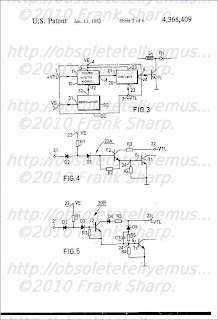
FIG. 3 shows in block diagram form the control circuit SC of FIG. 1.
This
control circuit SC comprises a pulse-width modulator stage 10 a first
input 11 of which, connected to input 1, receives flyback pulses of
positive polarity +VTL from the second secondary winding B3 of the line
transformer TL (see FIG. 1 and a second input 12 of which receives a
so-called regulating voltage or current whose level is proportional to
the difference between the actual output voltage VS and a constant
reference value, delivered by the output 32 of a regulating circuit or
stage 30 whose input 31 is connected through input 3 to the positive
output pole SP of the supply device BS supplying the regulated voltage
VS. The variation of the regulating current or voltage causes the
variation of the time instant when the instantaneous amplitude of a
sawtooth voltage waveform, either with substantially constant slope and
amplitude, reaches the level of this regulating voltage, or with a
slope variable depending of the regulating current (which is added to
the current for linearly charging a capacitor), reaches the
predetermined level of a fixed reference (threshold) voltage, with
respect to the beginning or the end of the sawtooth waveform. Thus a
two-level rectangular signal with constant periodicity is generated,
whose duty cycle varies as a function of the regulating current or
voltage. If it is arranged, which is possible, for a reduction of the
output voltage VS with respect to its nominal value defined by the
reference voltage, to cause an increase in the duty cycle and for an
increase in VS to have the opposite effect, regulation of this output
voltage VS is provided, which tends to be stabilized to this nominal
value.
The output 14 of modulator 10 supplies a first input 21
of the driver stage 20 of the first switching transistor T1, a second
input 22 of which receives the flyback pulses of negative polarity
-VTL, coming from the first secondary winding B2 of the line
transformer TL.
FIGS. 4 and 5 illustrate two different
embodiments of the driver stage 20 of FIG. 3, providing efficient turn
off of the first transistor T1.
In FIG. 4, the driver stage 20A
comprises a third supply input 23 which connected to the positive pole
(P) of the source of the (unregulated) input voltage VE and to one of
the terminals of a first resistor R1 (1.8 kiloohms) whose other
terminal is connected in parallel to the anodes of two diodes D2 and D3
(of type 1N4148). The second of these diodes D3 has its cathode
connected to the base of a third NPN transistor T2 and to one of the
terminals of a second resistor R2 (220 ohms). The emitter of the third
transistor T2 is connected to the other terminal of the second resistor
R2 and to the output 24 of stage 20A, which is connected through the
output 6 of the control circuit SC to the base of the first transistor
T1. The collector of the second transistor T2 is connected through a
third resistor R3 (10 ohms) to the second input 22 of stage 20A
receiving the signal -VTL which comprises the negative-going flyback
pulses and, between them, plateaux of a constant positive level (zero
average value). The base of the first transistor T1 is coupled to its
emitter and to ground G, through a fourth resistor R4 (100 ohms). The
third transistor T2 is thus mounted as a common collector
(emitter-follower) stage.
When
the output 14 of modulator 10 (FIG. 3) which is connected to the input
21 of stage 20A supplies a low state (level), i.e. a voltage close to
zero, the thus positively biased diode D2 becomes conducting so that
its anode will be at a voltage of a few tenths of a volt (0.7+V
CEsat )
which is less than the voltage required for making the three series PN
junctions orientated in the same direction conductive, the first of
which is formed by the third diode D3, the second is the base-emitter
junction of a third transistor T2 and the third that of the first
transistor T1, which will thus remain turned off. When, on the other
hand, output 14 supplies a high state or forms an open circuit (the
output stage of modulator 10 being formed by an open-collector
transistor), diode D2 is cut off by its reverse bias and the voltage VE
applied to the input 23 causes a current to flow through the first
resistor R1, the diode D3 and the respective base-emitter junctions of
transistors T2 and T1 connected in series. Under these circumstances
and if, at the same time, the voltage waveform -VTL applied to the
collector of transistor T3 presents its constant positive level
portion, coinciding with the trace periods of the horizontal scan,
transistors T2 and T1 become simultaneously saturated with the effect
previously described insofar as the supply device BS of FIG. 1 is
concerned. On the other hand, when the voltage waveform -VTL applied to
the collector of the third transistor T2 becomes negative, during
flyback periods, the current then flows between terminals 23 and 22 of
driver stage 20 A, through resistor R1, diode D3, the base-collector
junction of the third transistor T2 and resistor R3. The third
transistor T2 then operates along its symmetrical saturation
characteristics, i.e. it is inverted so that its collector becomes
emitter and vice versa. It then conducts a current in the reverse
direction between ground and the input 22 (negative) through the
resistor R4 across the terminals of which it causes, after removal of
the excess minority carriers from the base of the first transistor T1
through the third transistor T2, a voltage drop biasing said base
negatively with respect to the emitter. This negative voltage applied to
the base of reversely saturated transistor T3 allows a considerable
reduction in the storage time and a rapid turnoff of the first
transistor T1. Since the sawtooth generator of the pulse-width modulator
10 described above is controlled by positive-going flyback pulses, the
rectangular signal applied by its output 14 (FIG. 14) to input 21 of
stage 20A undergoes, during the flyback period following the turn off of
the first transistor T1, a transition from its high state to its low
state which causes diode D2 to conduct and, consequently, the third
transistor T2 (reversed) to be cut off before the waveform -VTL becomes
positive again and rebiases this transistor T2 the right way round.
FIG.
5 shows the schematic diagram of another embodiment of the driver
circuit 20 of FIG. 3, designated by 20B, which has only been modified
with respect to circuit 20A of FIG. 4 insofar as the collector circuit
of the third transistor T2 and the base circuit of the first transistor
T1 are concerned.
This modification is more particularly
intented for the case where the negative peak amplitude of the voltage
waveform -VTL applied to the base of the first transistor T1 through
resistor R3 and the emitter-collector path of the reversely saturated
third transistor T2, exceeds the reverse (Zener) avalanche-effect
breakdown voltage of one of the base-emitter or base-collector junctions
of the first transistor T1. This may occur when the first secondary
winding B2 of the line transformer TL is also used for other functions
in the television receiver.
To prevent the third transistor T2
from being reversely saturated (symmetrically), the circuit 20B
comprises a fourth diode D4 inserted between the input 22 receiving the
voltage waveform -VTL and the collector thereof, in series with the
resistor R3 and connected to conduct in the same direction as its
collector-emitter path. The input 22 is more over connected to the
cathode of a fifth diode D5 (1N4148) whose anode is connected through a
circuit formed by a fifth resistor R5 (330 ohms) and a third capacitor
C3 (1nF) connected in parallel, to the base of the first transistor T1.
Diode D5 isolates the base of transistor T1 from the input 22,
when the waveform -VTL is positive, and connects them together through a
resistive voltage divider formed by resistors R5 and R4 in series,
when it becomes negative. Capacitor C3 accelerates the turn-off by
favoring the transmission to the base of T1 of abrupt transitions of
the negative flybacd pulses.

FIG.
6 is a diagram, partly in block form, of a possible embodiment of the
pulse-width modulator 10 of the control circuit SC of FIG. 3. Diagrams
D, E and F of FIG. 7 show the voltage waveforms applied respectively to
the input 11 (+VTL) and supplied by the output SI (VI) of the sawtooth
generator GD and by the output 14 (VP) of circuit 10A.
Modulator
10A of FIG. 5 comprises a sawtooth generator GD formed by a
conventional integrator circuit comprising a first amplifier A1
(integrated operational amplifier, for example), an integrating resistor
R1 inserted in series between the input 11 receiving the voltage
waveform +VTL illustrated by Diagram D of FIG. 7 and supplied by the
second secondary winding B3 of the line transformer TL, and the input
(inverting) of amplifier A1, as well as an interating capacitor CI
connected between this input and the output SI of amplifier A1
(capacitive feedback). In response to this waveform +VTL, the output of
amplifier A1 forming the output SI of sawtooth generator GD, supplies a
voltage waveform VI illustrated by the diagram E of FIG. 7 which
comprises, during the period between time instants t0 and t2
corresponding to the trace period TA of the scan, a voltage decreasing
linearly between a maximum value (positive) and a minimum value
(negative), and during the flyback intervals preceding time instant t0
and succeding to time instant t2, an increasing voltage of substantially
semi-cosinusoidal shape.
Voltage VI is applied to one of the
inputs (-) of an analog voltage comparator which may be formed by means
of a second differential-type amplifier A2 (integrated operational
amplifier), whose other input (+) connected to the input 12 of modulator
10A, receives the regulating voltage VR supplied by the regulator
stage (30 of FIG. 3). This regulating voltage VR, which is obtained by
comparing the output voltage VS of the supply device BS of the circuit
of FIG. 1 with a reference voltage (VZ supplied by a Zener diode, for
example), is a DC voltage undergoing slow variations, shown in Diagram E
of FIG. 7 by a dash-dot line.
When the waveform VI applied to
the inverting input (-) of comparator A2 is greater than the regulating
voltage VR, which is the case during the period between time instants
t0 and t1, its output connected to the output 14 of modulator 10A
provides a low state. When, on the other hand, it (VI) reaches or
becomes less than VR, which occurs from the time instant t1, the output
14 of modulator 10A provides a high state (which causes saturation of
the first transistor T1). This high state continues until time instant
t4 subsequent to the time instant t2 of the beginning of the following
flyback pulse whose leading edge controls the turn-off of the first
transistor T1, when the waveform VI becomes greater than the regulating
voltage VR. Thus there is obtained at the output 14 of modulator 10A a
rectangular signal VP shown in Diagram F of FIG. 7, formed successively
of a low-level (zero or negative) beginning during the first half of
the flyback period TR and ending at time instant t1, and a high level
going from time instant t1 to time instant t4. Time instant t1 of the
positive transition of signal VP, which determines the beginning of
conduction of the first transistor T1 is then situated during the trace
period of the scan TA and its position with respect to the beginning t0
or to the end t2 thereof varies as a function of the regulating
voltage VR. When the regulating voltage VR is negative (as on the
Diagram E of FIG. 7), a predetermined fraction of the output voltage VS
is greater than the reference voltage, the duration of the high level
state (t2-t1) is less than half of the trace period of the scan T1. In
the opposite case, this duration (t2-t1) is greater than TA/2. The
modification of this duration (t2-t1) and thus of the duty cycle is
carried out in the reverse direction of the variation of the output
voltage VS so as to stabilize it at a previously adjusted level, with
respect to this reference voltage. The waveform -VTL may also be
applied to the input 11 of modulator 10A. In this case, the input of
comparator A2 must also be inverted.
To
obtain suitable operating limits, while taking into consideration
particularly the value of inductance L, the duty cycle or the durations
(t2-t1) must vary between 0, the case where the input voltage VE is
equal to the nominal output voltage VS, and about two-thirds, the case
where the maximum power is supplied for a minimum voltage at the input.
The ratio between the residual alternating voltage (hum) at the
output and the alternating voltage at the input must also allow an
image to be obtained which is not perturbed for the eye. A value less
than or equal to a hundredth for this ratio gives satisfactory results.

FIG.
8 shows the simplified diagram of a practical embodiment (by means of
discrete components) of the pulse-width modulator 10 of FIG. 3.
Different waveforms of a current I1 and input +VTL and output VP
voltages are respectively illustrated by the Diagrams H, J and K of FIG.
9.
The input 11 of modulator 10B of FIG. 3 receives the voltage
waveform +VTL which may be suppled either directly by the second
secondary winding B3 of line transformer TL, or through a coupling
capacitor whose one terminal is connected to the collector of the trace
switch transistor TH (see FIG. 1). This input 11 supplies a passive
shaping circuit, supplying negative-going (decreasing) sawtooth
waveforms during the trace periods of scan T1. This passive circuit
comprises a fourth coupling capacitor C4 (0.1μ) one terminal of which is
connected to the input 11 and the other of which is connected to one
of the terminals of a sixth resistor R6 (10 Kohms). The other terminal
of this resistor R6 is connected to one of the terminals of a seventh
resistor R7 (5.6 Kohms), to one of the terminals of a fifth capacitor C5
(5.6 nF) and to the anode of a sixth diode D6. The other terminal of
capacitor C5 is connected to ground G. The cathode of the sixth diode D6
and the other terminal of resistor R7 are both connected to one of the
terminals of an eighth resistor R8 (33 kohms), to that of a ninth
resistor R9 (470 ohms), to that of a sixth capacitor C6 (4.7 nF) and to
the regulation input 12 of modulator 10B, which is connected to the
output 32 of the regulator stage 30 (see FIG. 3). The other terminal of
capacitor C6 is connected to ground. The other terminal of resistor R8
is connected to the supply input 13 of modulator 10B receiving the
input voltage VE. The other terminal of the ninth resistor R9 is
connected to the base of a fourth NPN transistor T3, which forms the
voltage comparator stage, whose emitter is connected to ground and
whose collector (open), which forms the output 14 of modulator 10 B, is
connected to the input 21 of the driver stage 20A (of FIG. 4) or 20B
(of FIG. 5), formed by the cathode of the second diode D2. The value of
capacitor C6 has been chosen so as to limit the maximum negative
voltage applied to the base-emitter junction of transistor T3 to a
value less than its reverse avalanche breakdown voltage. When the input
voltage waveform +VTL is positive, as during the major portion of the
flyback periods TR, diode D6 short-circuits resistor R7 and we have
then a simple passive RC integrator formed by resistor R6 in series and
two capacitors C5 and C6 in parallel, whose output is connected to the
base of transistor T3 through resistor R9. Transistor T3 becomes
conducting when its base current IB formed by the sum of currents I1
and I2 becomes positive. The current I1 shown by an arrow in FIG. 8 and
on the Diagram H of FIG. 9, results from the application of the +VTL
waveform of Diagram J to the above-mentionned simple integrator, during
its positive alternation, and to the cascaded double integrator R6,
C5, R7, C6 during its negative plateau going from t0 to t2. During this
negative voltage plateau of the +VTL signal, the current I1 becomes
negative and linearly decreasing. When the instantaneous negative
amplitude of current I1 becomes equal to the positive current I2 shown
by another arrow in FIG. 8 and by means of a reversed constant level
(-I2) shown by a broken line in diagram H of FIG. 7, which occurs at
time t1, the base current of transistor T3 is cancelled out and this
latter is cut off. Since the current I2 is due for a large part to the
regulating current IR supplied by the output of the regulator stage (30
in FIG. 3) and proportional to the error voltage, the duration of the
cut-off state (t4-t1) of transistor T3 and, consequently, that (t2-t1)
of the saturated state of the first transistor T1 (as well as the duty
cycle) will vary reversely to the variation of this current IR. The
current IE shown by an arrow in FIG. 8, which flows through the
high-value resistor R8 from the input voltage source VE and which is
one of the components with IR of current I2, forms a small current for
maintaining transistor T3 saturated in the absence of flyback pulses
and thus of horizontal deflection. The fact that resistor R8 is
supplied by the unregulated input voltage VE allows another parameter
to be added for acting on the duty cycle of transistor T3 as a function
thereof. Diagram K of FIG. 9 illustrates the rectangular signal VP
obtained at the output 14 of the modulator 10B of FIG. 8.

FIG.
10 is a schematic diagram of a conventional regulator stage 30 of the
control circuit of FIG. 3. It is formed essentially by a well-known
circuit called differential amplifier having two inputs, the first of
which receives an adjustable fraction of the voltage to be stabilized,
formed, in the present case, by the output voltage VS of the power
supply device (BS, FIG. 1) and the second input of which receives a
stable reference voltage which is generally generated within this stage
(as in most known ballast or switched-mode voltage regulator).
The
reference voltage VZ is here produced by means of a Zener diode D7 (of
the BZX83C type having a stabilized Zener voltage of 7.5 V) whose
cathode is connected to the input 31 receiving the output voltage VS of
the device BS (FIG. 1) and whose anode is connected through an eleventh
resistor R11 (10 Kohms) to ground G. The second input of the
differential amplifier used here is formed by the emitter of a fifth PNP
transistor T4 which is connected to the anode of the Zener diode D7.
The voltage (VS-VZ) biasing this emitter is then fixed with respect to
the output voltage VS. The first input of the differential amplifier is
here formed by the base of transistor T4 which is biased by a
voltage-divider circuit, formed from a fifteenth resistor R15 (4.7
Kohms), a potentiometer R16 (5 Kohms) and a fourteenth resistor R14 (22
Kohms) connected in series between the input terminal 31 and ground G.
The base of transistor T4, connected to the slider of potentiometer R16
receives then a previously adjusted fraction of the output voltage VS
supplying the horizontal deflection circuit (SH), so that it forms a
constant current generator supplying a current proportional to its
emitter-base voltage which is equal to the difference (error voltage)
between the reference voltage VZ and the selected fraction of the output
voltage VS supplied by potentiometer R16. The collector of the fourth
transistor T4, connected by a tenth resistor R10 (2.2 Kohms) to the
output 32, supplies then the regulating current IR to the regulating
input (12, FIGS. 3 and 8) of the pulse-width modulator (10 or 10B, FIGS.
3 and 8).
It will be noted here that a feedback circuit
comprising a twelfth resistor R12 (5.6 Kohms) and a seventh capacitor C7
(4.7 nF) in series connects the collector of transistor 14 to its
base.
The difference between the voltage respectively provided
by the potentiometer R16 and the Zener diode D7 causes more or less
heavy conduction of transistor T4 which delivers the current IR.
In
short, when the output voltage VS increases, the voltage (VS-VZ) at
the emitter of transistor T4 increases more than that applied to its
base and current IR increases. The value of I1 at which transistor T3
is cut off increases then in absolute value and this transistor T3 is
turned off later, which reduces the conducting period of transistor T1.
The peak current in inductance L then diminishes, which causes a
reduction of the output voltage VS which comes back to its nominal
value, taking into account the residual error required for controlled
operation.
FIG. 11 shows the complete simplified diagram of a
power supply device BS of FIG. 1 whose control circuit SCA is
respectively formed by the driver circuit 20A of FIG. 4, by the
modulator 10B of FIG. 8 and the regulator stage 30 of FIG. 10, except
for a few variations.
The variations concern a damping resistor
R17 of 1 kiloohm shunting the inductance L, resistor R8 and resistor
R10 which are both connected directly to the base of transistor T3
instead of being connected to the cathode of diode D6, resistor R11
which has been omitted and a resistor R13 which shunts the slider of
potentiometer R16 to ground. These details of construction have no
influence at all on the operation of the circuit such as it has been
described above, but simply allow easier adjustment.

Another
embodiment is shown in FIG. 12. It allows more especially a television
set to be supplied with power in which the horizontal deflection
circuit operates from a higher DC voltage VS, of about 100 volts for
example, itself obtained from an initial output voltage VSI of about 60
volts. The operation of the circuit is fundamentally the same as that
of FIG. 11 and only the differences will be described below. The
components playing the same role in both diagrams bear the same
references. The values may however be different but their dimensioning
is within the scope of a man skilled in the art. The voltage VS
delivered by the power supply is used principally in the horizontal
deflection circuit which is the component consuming most power in the
television set. The power supply circuit components receiving
permanently a voltage when the horizontal deflection circuit is not
operating, but when the mains is connected, are solely those
indispensable for activating the power supply, i.e. the first switching
transistor T1 and the circuit for measuring the output voltage in the
regulator stage 300.
To simplify the driver stage 100, instead
of the single switching transistor T1, an integrated Darlington circuit
T10 is used of the BU 807 type, for example. Therefore, the gain is
sufficient to omit a discrete driver transistor T2 and to connect the
cathode of diode D3 directly to the base input of T10. The negative
-VTH pulses, coming from an intermediate tapping on coil B2 of the line
output transformer, are applied directly to the base of T10 through
resistor R3 which is connected in series with a diode D9 whose cathode
is connected to this intermediate tapping.
Instead of the input
voltage VE, the power supply input 4 of the control circuit SCB is fed
by a voltage obtained by rectifying the positive half-waves (plateaux)
of the -VTL voltage supplied by the first secondary winding B2, by
means of a diode D8 and a capacitor C8. Thus considerably lower voltage
may be obtained than that supplying the horizontal deflection circuit,
of the order of 13 volts, for example. A voltage of this value allows
video amplification circuits as well as other circuits of the
television set to be supplied while providing for these latter a very
great reliability. This voltage is applied through resistor R1 to the
anodes of diodes D2 and D3 and through resistor R8 to the base of the
transistor T3 of modulator 10B.
The regulator stage 300 here
comprises two PNP transistors T4 and T5 connected differentially. For
that, their emitters receive the voltage rectified by D8 through a
resistor R18 of 1.5 kiloohms. The collector of transistor T5 is
connected to ground through a resistor R20 of 3.9 kiloohms and the
collector of transistor T4, which supplies the regulating current IR,
is connected to the cathode of diode D6 through a resistor R10 of 4.7
kiloohms.
The reference voltage (6.2 volts) is supplied by a
Zener diode D7 whose anode is connected to ground, and cathode to a
resistor R19 (6.8 kiloohms) which receives the voltage rectified by D8.
This reference voltage is applied to the base of transistor 14. A
capacitor C9 (49 microfarads) shunts diode D7 so as to cause the
reference voltage to rise gradually when the apparatus is switched on,
which allows a gradual rise of the output voltage VS to be obtained.
A
potentiometer R16 of 10 kiloohms connected between two stopper
resistors R15 (68 kiloohms) and R14 (5.6 kiloohms) receives the voltage
VS through the resistor R15 and is connected to ground through
resistor R14. The sliding contact of potentiometer R16 allows a
fraction of the voltage VS to be applied to the base T5. A resistor R13
(47 kiloohms) also connects this base to the common point between R15
and R16.
An anti-oscillation capacitor C10 (15 nanofarads) connects the base of the collector of transistor T5.
Thus
the regulating current IR supplied by resistor R10 is directly
dependent on the difference between the output voltage VS, applied to
the horizontal deflection circuit, and the reference voltage determined
by the Zener diode D7. The power supply BS thus stabilizes this voltage
VS and at the same time the rectified voltage supplied by diode D8.
To
stop this power supply, as well as that of FIG. 11 moreover, it is
sufficient to stop by means of a remote control receiver, for example,
the operation of the horizontal oscillator.
In
this case, the input voltage VE is still present, but is considerably
smaller than voltage VS. For the power supply of FIG. 12, this reduced
voltage is only applied to the Darlington transistor T10 and a fraction
thereof to the base of transistor T5 of the regulator stage 300. Thus
the life expectation of the other components of the device BS is
increased. Since the voltage supplied by diode D8 is itself regulated,
it may be used for supplying a major portion of the television set,
except for the horizontal deflection circuit supplied by voltage VS and
the remote control receiver which must be capable of operating
permanently (also in the ready state) so as to detect the turn-on
control signal. The protection which was mentioned earlier on is then
extended to the greatest part of the components of the television set.
It
will be noted here that the three stages 10, 20 and 30 of control
circuit SC (see FIGS. 1 and 3) may be formed by means of circuits
different from those described and shown and which are known per se,
and that it is sufficient to have a secondary winding B2 (in addition
to the very-high-voltage winding) of the line transformer TL, supplying
negative line-flyback pulses which may be used for generating a
decreasing or increasing sawtooth voltage waveform as well as for
controlling the cutting off of the first switching transistor T1.

CRT TV EHT VOLTAGE MULTIPLIER - KASKADE COCKCROFT-WALTON CASCADE CIRCUIT FOR VOLTAGE MULTIPLICATION:
A
Cockcroft-Walton cascade circuit comprises an input voltage source and a
pumping and storage circuit with a series array of capacitors with
pumping and storage portions of the circuit being interconnected by
silicon rectifiers, constructed and arranged so that at least the
capacitor nearest the voltage source, and preferably one or more of the
next adjacent capacitors in the series array, have lower tendency to
internally discharge than the capacitors in the array more remote from
the voltage source.
1. An improved voltage multiplying circuit comprising,
2.
An improved voltage multiplying circuit in accordance with claim 1
wherein said first pumping capacitor is a self-healing impregnated
capacitor which is impregnated with a high voltage impregnant.
3.
An improved voltage multiplying circuit in accordance with claim 1
wherein said first pumping capacitor comprises a foil capacitor.
Description:
BACKGROUND OF THE INVENTION
The
invention relates in general to Cockcroft-Walton cascade circuits for
voltage multiplication and more particularly to such circuits with a
pumping circuit and a storage circuit composed of capacitors connected
in series, said pumping circuits and storage circuit being linked with
one another by a rectifier circuit whose rectifiers are preferably
silicon rectifiers, especially for a switching arrangement sensitive to
internal discharges of capacitors, and more especially a switching
arrangement containing transistors, and especially an image tube
switching arrangement.
Voltage multiplication cascades composed
of capacitors and rectifiers are used to produce high D.C. voltages from
sinusoidal or pulsed alternating voltages. All known voltage
multiplication cascades and voltage multipliers are designed to be
capacitance-symmetrical, i.e., all capacitors used have the same
capacitance. If U for example is the maximum value of an applied
alternating voltage, the input capacitor connected directly to the
alternating voltage source is charged to a D.C. voltage with a value U,
while all other capacitors are charged to the value of 2U. Therefore, a
total voltage can be obtained from the series-connected capacitors of a
capacitor array.
In voltage multipliers, internal resistance is
highly significant. In order to obtain high load currents on the D.C.
side, the emphasis in the prior art has been on constructing voltage
multipliers with internal resistances that are as low as possible.
Internal
resistance of voltage multipliers can be reduced by increasing the
capacitances of the individual capacitors by equal amounts. However, the
critical significance of size of the assembly in the practical
application of a voltage multiplier, limits the extent to which
capacitance of the individual capacitors can be increased as a practical
matter.
In television sets, especially color television sets,
voltage multiplication cascades are required whose internal resistance
is generally 400 to 500 kOhms. Thus far, it has been possible to achieve
this low internal resistance with small dimensions only by using
silicon diodes as rectifiers and metallized film capacitors as the
capacitors.
When silicon rectifiers are used to achieve low
internal resistance, their low forward resistance produces high peak
currents and therefore leads to problems involving the pulse resistance
of the capacitors. Metallized film capacitors are used because of space
requirements, i.e., in order to ensure that the assembly will have the
smallest possible dimensions, and also for cost reasons. These film
capacitors have a self-healing effect, in which the damage caused to the
capacitor by partial evaporation of the metal coating around the point
of puncture (pinhole), which develops as a result of internal
spark-overs, is cured again. This selfhealing effect is highly desirable
as far as the capacitors themselves are concerned, but is not without
its disadvantages as far as the other cirucit components are concerned,
especially the silicon rectifiers, the image tubes, and the components
which conduct the image tube voltage.
It is therefore an important object of the invention to improve voltage multiplication cascades of the type described above.
It is a further object of the invention to keep the size of the entire assembly small and the internal resistance low.
It is a further object of the invention to increase pulse resistance of the entire circuit.
It is a further object of the invention to avoid the above-described disadvantageous effects on adjacent elements.
It
is a further object of the invention to achieve multiples of the
foregoing objects and preferably all of them consistent with each other.
SUMMARY OF THE INVENTION
In
accordance with the invention, the foregoing objects are met by making
at least one of the capacitors in the pumping circuit, preferably
including the one which is adjacent to the input voltage source, one
which is less prone to internal discharges than any of the individual
capacitors in the storage circuit.
The Cockcroft-Walton cascade
circuit is not provided with identical capacitors. Instead, the
individual capacitors are arranged according to their loads and designed
in such a way that a higher pulse resistance is attained only in
certain capacitors. It can be shown that the load produced by the
voltage in all the capacitors in the multiplication circuit is
approximately the same. But the pulse currents of the capacitors as well
as their forward flow angles are different. In particular, the
capacitors of the pumping circuit are subjected to very high loads in a
pulsed mode. In the voltage multiplication cascade according to the
invention, these capacitors are arranged so that they exhibit fewer
internal discharges than the capacitors in the storage circuit.
The
external dimensions of the entire assembly would be unacceptably large
if one constructed the entire switching arrangement using such
capacitors.
The voltage multiplication cascade according to the invention also makes it possible to construct a reliably operating
arrangement
which has no tendency toward spark-overs, consistent with satisfactory
internal resistance of the voltage multiplication cascade and small
dimensions of the entire assembly. This avoids the above cited
disadvantages with respect to the particularly sensitive components in
the rest of the circuit and makes it possible to design voltage
multiplication cascades with silicon rectifiers, which are characterized
by long lifetimes. Hence, a voltage multiplication cascade has been
developed particularly for image tube circuits in television sets,
especially color television sets, and this cascade satisfies the highest
requirements in addition to having an average lifetime which in every
case is greater than that of the television set.
A further aspect
of the invention is that at least one of the capacitors that are less
prone to internal discharges is a capacitor which is impregnated with a
high-voltage impregnating substance, especially a high-voltage oil such
as polybutene or silicone oil, or mixtures thereof. In contrast to
capacitors made of metallized film which have not been impregnated, this
allows the discharge frequency due to internal discharges or
spark-overs to be reduced by a factor of 10 to 100.
According to a
further important aspect of the invention, at least one of the
capacitors that are less prone to internal discharges is either a foil
capacitor or a self-healing capacitor. In addition, the capacitor in the
pumping circuit which is adjacent to the voltage source input can be a
foil capacitor which has been impregnated in the manner described above,
while the next capacitor in the pumping circuit is a self-healing
capacitor impregnated in the same fashion.
Other objects,
features and advantages of the invention will be apparent from the
following detailed description of preferred embodiments, taken in
connection with the accompanying drawing, the single FIGURE of which:
BRIEF DESCRIPTION OF THE DRAWING
is a schematic diagram of a circuit made according to a preferred embodiment of the invention.
DETAILED DESCRIPTION OF PREFERRED EMBODIMENTS
The
voltage multiplier comprises capacitors C1 to C5 and rectifiers D1 to
D5 connected in a cascade. An alternating voltage source UE is connected
to terminals 1 and 2, said voltage source supplying for example a
pulsed alternating voltage. Capacitors C1 and C2 form the pumping
circuit while capacitors C3, C4 and C5 form the storage circuit.
In
the steady state, capacitor C1 is charged to the maximum value of the
alternating voltage UE as are the other capacitors C2 to C5. The desired
high D.C. voltage UA is picked off at terminals 3 and 4, said D.C.
voltage being composed of the D.C. voltages from capacitors C3 to C5.
Terminal 3 and terminal 2 are connected to one pole of the alternating
voltage source UE feeding the circuit, which can be at ground potential.
In the circuit described here, a D.C. voltage UA can be picked off
whose voltage value is approximately 3 times the maximum value of the
pulsed alternating voltage UE. By using more than five capacitors, a
correspondingly higher D.C. voltage can be obtained.
The
individual capacitors are discharged by disconnecting D.C. voltage UA.
However, they are constantly being recharged by the electrical energy
supplied by the alternating voltage source UE, so that the voltage
multiplier can be continuously charged on the output side.
According
to the invention, in this preferred embodiment, capacitor C1 and/or C2
in the pumping circuit are designed so that they have a lower tendency
toward internal discharges than any of the individual capacitors C3, C4
and C5 in the storage circuit.
It is evident that those skilled
in the art, once given the benefit of the foregoing disclosure, may now
make numerous other uses and modifications of, and departures from the
specific embodiments described herein without departing from the
inventive concepts. Consequently, the invention is to be construed as
embracing each and every novel feature and novel combination of features
present in, or possessed by, the apparatus and techniques herein
disclosed and limited solely by the scope and spirit of the appended
claims.
Inventors:Petrick, Paul (Landshut, DT)
Schwedler, Hans-peter (Landshut, DT)
Holzer, Alfred (Schonbrunn, DT)
ERNST ROEDERSTEIN SPEZIALFABRIK
US Patent References:
3714528 ELECTRICAL CAPACITOR WITH FILM-PAPER DIELECTRIC 1973-01-30 Vail
3699410 SELF-HEALING ELECTRICAL CONDENSER 1972-10-17 Maylandt
3463992 ELECTRICAL CAPACITOR SYSTEMS HAVING LONG-TERM STORAGE CHARACTERISTICS 1969-08-26 Solberg
3457478 WOUND FILM CAPACITORS 1969-07-22 Lehrer
3363156 Capacitor with a polyolefin dielectric 1968-01-09 Cox
2213199 Voltage multiplier 1940-09-03 Bouwers et al.
Digital phase locked loop tuning system / PLL FREQUENCY SYNTHESIZER:(ITT SAA1274 SAA1275 SAA1276)
A phase locked loop circuit for use in an automatic frequency
synthesizing system. The system includes a programmer circuit which is
responsive to a channel number input signal and generates a first
digital control signal which is representative of the selected channel
number and a second digital control signal which is representative of a
predetermined group of channel numbers. A programmable divider is
controlled by the programming circuit and generates a digital output
signal which causes the phase locked loop circuit to generate a desired
system output frequency corresponding to the selected channel number
input signal. The phase locked loop circuit includes automatic fine
tuning and manual fine tuning features.
1. A digital phase locked loop tuning system responsive to a local
oscillator signal for producing a frequency synthesized digital output
signal which is utilized to control the frequency of the local
oscillator, the local oscillator having a plurality of frequencies
associated therewith corresponding, respectively, to a plurality of
selectable channels, each of the channels being allocated to one of at
least two channel groups with each channel in a particular channel
group being separated from an adjacent channel in the particular
channel group by a predetermined frequency spacing of the local
oscillator, comprising:
programming means responsive to an input signal representing a
selected channel number of a particular channel group for generating a
first digital control signal having a value corresponding to the
selected channel number and for generating a second digital control
signal representative of said particular channel group, said second
digital control signal being a constant predetermined value for all of
said channel numbers that are within said group; and
programmable divider means coupled to said programming means being
responsive to said first, second digital control signals and the local
oscillator signal, in a local oscillator mode, for generating the
digital output signal which is representative of a desired frequency
corresponding to said selected channel number, said programmable divider
means including means for dividing the local oscillator signal by
first and second factors, said first factor being related to the
frequency separation between local oscillator signals by an integral
number, the local oscillator signal being divided by said first factor
during a first interval for a first number of periods of the output
signal and being divided by said second factor for a second number of
periods of the output signal, said first number of periods being
related to the number of the channel selected, said second number being
related to the channel group within which the selected channel lies.
2. Phase locked loop system according to claim 1, wherein said
programming means including means coupled to said programming means for
receiving an MFT signal and being responsive to said MFT signal for
altering said first and second digital control signals, and said
programmable divider means being responsive to said altered digital
control signals for generating an altered system output frequency.
3. Phase locked loop system
according to claim 2, wherein said programming means includes first
terminal means coupled to said programming means for receiving an AFT
control signal, and first logic means responsive to the input signal
and the AFT control signal for generating the first digital control
signal. 4. Phase locked loop
system according to claim 3, wherein said programming means includes
second logic means coupled to said first logic means and responsive to
the AFT control signal for generating the second digital control
signal. 5. Phase locked loop
system according to claim 4, wherein said second logic means includes
group decoder means coupled to said first logic means.
6. Phase locked loop circuit means according
to claim 5, wherein said second logic means includes memory means
coupled to said group decoder means and to said first terminal means.
7. Phase locked loop system
according to claim 6, wherein said second logic means includes second
terminal means for receiving an MFT signal, and up/down counter latch
means coupled to said memory means and to said second terminal means
for altering said first and second digital control signals in response
to said MFT signal. 8. Phase
locked loop system according to claim 7, wherein said second logic
means includes adder means coupled to said up/down counter latch means
to said memory means. 9. Phase
locked loop system according to claim 3, wherein said first logic
means includes channel number generator means coupled to said first
terminal means and responsive to said input signal.
10. Phase locked loop system according to claim
9, wherein said channel number generator means includes first and
second data selector means coupled to said first terminal means, and
adder means coupled to said second data selector means and to said
up/down counter latch means.
11. Phase locked loop system according to claim 1, wherein said means
for dividing the local oscillator signal includes programmable counter
means for generating a modulus control output signal, and variable
modulus prescaler divider means coupled to and responsive to said
programmable counter means, said variable modulus prescaler divider
means dividing the local oscillator signal by said first and second
factors. 12. Phase locked loop
system according to claim 11, wherein said programmable counter means
includes third data selector means coupled to receive said first and
second digital control signals and said modulus control signal.
13. Phase locked loop system
according to claim 12, wherein said programmable counter means
includes a programmable counter coupled to said third data selector
means and to said variable modulus prescaler divider means.
14. Phase locked loop system according to
claim 13, wherein said programmable counter means includes look ahead
circuit means coupled to said programmable counter, and divide by two
circuit means coupled to said look ahead circuit means for generating
said modulus control output signal.
15. Phase locked loop tuning system according to claim 1
including digital automatic fine tuning (AFT) means wherein:
said programmable divider means includes switching means responsive to
an AFT control signal to inhibit the local oscillator signal to said
programmable divider means and to provide an input signal thereto of a
different frequency than the local oscillator signal; and
said programming means including logic means responsive to said AFT
control signal for altering said first and second digital control
signals to predetermined values to cause the phase locked loop tuning
system to be operable in an automatic fine tuning mode.
16. Phase locked loop tuning system of claim 15 wherein said programmable divider means includes:
programmable counter means for generating first and second modulus control signals; and
dual modulus prescaler means responsive to said first modulus control
signal for dividing the local oscillator signal in said local
oscillator mode and said input signal of a different frequency in said
automatic fine tuning mode by said first factor which is equal to the
integer six and being responsive to said second modulus control signal
for dividing said local oscillator signal and said input signal of a
different frequency by said second factor which is equal to the integer
five respectively.
17. Phase locked loop tuning system of claim 16 wherein said signal of
a different frequency is an intermediate frequency signal provided by
the tuning system and supplied to said switching means.

18. In a phase locked loop tuning system for receiving a channel number
input signal and a local oscillator signal having groups of
selectable frequencies wherein the frequency spacing between each
adjacent local oscillator frequency within a single group is uniform,
the improvement comprising programmable divider means for generating a
digital output signal representative of a desired tuning system output
frequency including variable modulus prescaler divider means having a
prescaler division ratio being equal to P = S/Y' for dividing the
local oscillator frequency by said prescaler division ratio during a
first interval for a first number of periods of the digital output
signal and for dividing the local oscillator frequency by a second
prescaler division ratio during a second interval for a second number
of periods, said second ratio being related to said first ratio, where
S is the frequency spacing between each adjacent local oscillator
frequency within a single group (i), Y
i =D
i -X
i S, where D
i is said desired tuning system output frequency within said selected group; X
i =D
i /S rounded off to the nearest integer; Y' is chosen such that Y
i /Y' is an integer and S/Y' is an integer and Y' is the smallest value of all values of Y
i.
19. In a receiver including a
tuning apparatus for providing a plurality of local oscillator signals
each corresponding to a respective one of a plurality of selectable
channels, each of the channels being allocated to one of at least two
channel groups wherein each channel is separated from an adjacent
channel in the respective channel group by a predetermined frequency
spacing, a phase locked loop tuning system for producing a frequency
synthesized output signal for controlling the frequency of the local
oscillator, comprising:
variable modulus divider means for selectively dividing the frequency
of the local oscillator signal by first and second factors in response
to a modulus control signal to provide an output signal, said first
factor being related to the frequency separation between local
oscillator signals by an integral number; and
programmable means for generating said modulus control signal to cause
said variable modulus divider means to divide by said first factor
during a first interval for a first number of periods of said output
signal and to divide by said second factor during a second interval for
a second number of periods of said output signal, said first number
of periods being related to the number of the channel selected, said
second number of periods being related to the channel group
corresponding to the selected channel.
20. The phase locked loop tuning system of claim 19 wherein said programmable means includes:
programming means responsive to a selected channel input signal for
producing first and second digital output signals, said first digital
output signal being related to the selected channel number plus one of
two constant values which are determined in accordance within which
channel group the selected channel input signal lies, said second
digital signal being a constant value for all selected channels within a
channel group; and
programmable divider means responsive to said first and second digital
output signals from said programming means for providing said
variable modulus control signal and the frequency synthesized output
signal.
21. The phase locked loop tuning system of claim 20 wherein said
programming means includes automatic fine tuning (AFT) means responsive
to a AFT control signal being applied thereto when the receiver is
placed in an AFT mode wherein:
said variable modulus divider means is caused to receive a input signal different from the local oscillator signal;
said programming means being responsive to the AFT control signal for
altering said first and second digital signals such that the receiver
is finely tuned to the frequency of the received signal applied to the
receiver.
22. The phase locked loop tuning system of claim 21 wherein said
programming means includes means for receiving a manual fine tuning
(MFT) signal for altering said first and second digital output signals,
and said programmable divider means being responsive to said altered
digital control signals for generating an altered output signal.
23. The phase locked loop tuning
system of claim 19 wherein the one of said first and second factors is
an even number and the other is an odd number.
24. The phase locked loop tuning system of claim 23
wherein said first factor is the integer six and said second factor is
the integer five.
Description:
BACKGROUND OF THE INVENTION
This invention relates to digital tuning systems, and more
particularly, to a simplified digital phase locked loop (PLL) tuning
system incorporating unique digital automatic fine tuning and manual
fine tuning schemes.
Since the appearance of varactor tuners for television, many tuning
address schemes have evolved for controlling them. PLL techniques have
maintained a performance advantage but have suffered a cost
disadvantage due to complexity, the high frequencies involved, the
need for automatic fine tuning and in some localities, the need for a
manual fine tuning arrangement. With the advances that have taken
place in semiconductor technology in the last several years, the high
operating frequencies no longer present a significant problem.
Prior art PLL systems for use in television tuners have not yet been
able to incorporate an automatic fine tuning feature, nor have they
been able to incorporate a manual fine tuning system which would
enable the PLL tuning system to be intentionally offset in
predetermined increments. Television sets normally have an automatic
fine tuning (AFT) feature, but this is normally incorporated as a
separate circuit which is not directly incorporated into the television
tuner.
An additional disadvantage of prior art PLL systems which are designed
for use in a television tuner environment is that they are highly
complex and relatively expensive. In order to convert the channel
number input into the proper digital control signals for the PLL, a
relatively large ROM having a capacity on the order of 82 words by 12
bits was required. The best prior art PLL tuning systems require two
high speed programmable counters which greatly increase the system
complexity. This together with the large ROM which the system required,
greatly decreased the cost effectiveness of the system so that
commercial manufacturers were able to use these prior art PLL systems
only in their most expensive commercial television receivers.
Therefore, it is a feature of this invention to provide a digital PLL
tuning system which incorporates design techniques that vastly simplify
the complexity of the PLL while at the same time allowing the system
to meet the latest needs of a television tuning system or any other
PLL tuning system which is addressed by a channel number.
It is another feature of this invention to provide a digital PLL
tuning system that has the ability to automatically tune nonprecise
station frequencies and the ability to be manually fine tuned.
It is yet another feature of the present invention to provide a
digital PLL tuning system having only a single high speed programmable
counter and requiring a ROM capacity of only 5 words by 9 bits.
It is still another feature of this invention to provide a digital PLL
tuning system which performs the automatic fine tuning feature by
utilizing the PLL tuning system as a digital discriminator.
It is yet another feature of this invention to provide a digital PLL
tuning system incorporating a manual fine tuning (MFT) arrangement
which is capable of intentionally offsetting the local oscillator
frequency of a TV tuner in one megahertz steps or of offsetting TV IF
frequency in steps of 125 kilohertz.
SUMMARY OF THE INVENTION
The preferred embodiment of the present invention includes a phase
locked loop circuit means for an automatic frequency synthesizing
system. The phase locked loop circuit means includes programming means
which is responsive to an input signal representing a selected channel
number for generating a first digital control signal representative
of the selected channel number and for generating a second digital
control signal representative of a predetermined group of channel
numbers. A programmable divider means is coupled to the first and
second digital control signals and generates a digital output signal
representative of a desired system output frequency corresponding to
the selected channel number.
The phase locked loop circuit means further includes an automatic fine
tuning feature for fine tuning the phase locked loop output frequency
to the exact frequency of the received signal. The system further
includes a manual fine tuning provision which allows the phase locked
loop operating frequency to be intentionally offset in predetermined
increments.


 Consequently many commercially available
television apparatuses include a separate SCART connectors each
dedicated to receive input television signals in one of an RGB format
and an S-Video format. This limits the functionality of the SCART
connectors. In practical terms, the number of SCART connectors which can
be provided on a television apparatus is limited by cost and space
considerations. However, different users wish the input a wide range of
different combinations of formats of television signals, depending on
the equipment they personally own and use. However, the provision of
SCART connectors dedicated to input television signals in one of an RGB
format and an S-Video format limits the overall connectivity of the
television apparatus. Furthermore, for many users the different RGB
format and S-Video format are confusing. Some users may not understand
or may mistake the format of a television signal being supplied on a
given cable from a given piece of equipment. This can result in the
supply of input television signals of an inappropriate format for the
SCART connector concerned.
 (1885-1940) in Dresden. Following the destruction of the plant during the bombing raids in 1945, Martin Mende (the founder's son) created a new company in Bremen in 1947, in a former Focke-Wulf plant, under the name North German Mende Broadcast GmbH.
The name was subsequently changed to Nordmende: subsequently the
company became one of the prominent German manufacturers of radios,
televisions, tape recorders and record players in the 1950s and 1960s.

 Nordmende
was well known for its televisions throughout Ireland during the
1970s and 1980s, the company bought the rights to the name and
launched a range of white goods including fridges, freezers, washing machines, and dishwashers, alongside a revamped range of flat-screen TVs and stereos.


