Richtige Fernseher haben Röhren!

Richtige Fernseher haben Röhren!

In Brief: On this site you will find pictures and information about some of the electronic, electrical and electrotechnical Obsolete technology relics that the Frank Sharp Private museum has accumulated over the years .
Premise: There are lots of vintage electrical and electronic items that have not survived well or even completely disappeared and forgotten.

Or are not being collected nowadays in proportion to their significance or prevalence in their heyday, this is bad and the main part of the death land. The heavy, ugly sarcophagus; models with few endearing qualities, devices that have some over-riding disadvantage to ownership such as heavy weight,toxicity or inflated value when dismantled, tend to be under-represented by all but the most comprehensive collections and museums. They get relegated to the bottom of the wants list, derided as 'more trouble than they are worth', or just forgotten entirely. As a result, I started to notice gaps in the current representation of the history of electronic and electrical technology to the interested member of the public.

Following this idea around a bit, convinced me that a collection of the peculiar alone could not hope to survive on its own merits, but a museum that gave equal display space to the popular and the unpopular, would bring things to the attention of the average person that he has previously passed by or been shielded from. It's a matter of culture. From this, the Obsolete Technology Tellye Web Museum concept developed and all my other things too. It's an open platform for all electrical Electronic TV technology to have its few, but NOT last, moments of fame in a working, hand-on environment. We'll never own Colossus or Faraday's first transformer, but I can show things that you can't see at the Science Museum, and let you play with things that the Smithsonian can't allow people to touch, because my remit is different.

There was a society once that was the polar opposite of our disposable, junk society. A whole nation was built on the idea of placing quality before quantity in all things. The goal was not “more and newer,” but “better and higher" .This attitude was reflected not only in the manufacturing of material goods, but also in the realms of art and architecture, as well as in the social fabric of everyday life. The goal was for each new cohort of children to stand on a higher level than the preceding cohort: they were to be healthier, stronger, more intelligent, and more vibrant in every way.

The society that prioritized human, social and material quality is a Winner. Truly, it is the high point of all Western civilization. Consequently, its defeat meant the defeat of civilization itself.

Today, the West is headed for the abyss. For the ultimate fate of our disposable society is for that society itself to be disposed of. And this will happen sooner, rather than later.

OLD, but ORIGINAL, Well made, Funny, Not remotely controlled............. and not Made in CHINA.

How to use the site:
- If you landed here via any Search Engine, you will get what you searched for and you can search more using the search this blog feature provided by Google. You can visit more posts scrolling the left blog archive of all posts of the month/year,
or you can click on the main photo-page to start from the main page. Doing so it starts from the most recent post to the older post simple clicking on the Older Post button on the bottom of each page after reading , post after post.

You can even visit all posts, time to time, when reaching the bottom end of each page and click on the Older Post button.

- If you arrived here at the main page via bookmark you can visit all the site scrolling the left blog archive of all posts of the month/year pointing were you want , or more simple You can even visit all blog posts, from newer to older, clicking at the end of each bottom page on the Older Post button.
So you can see all the blog/site content surfing all pages in it.

- The search this blog feature provided by Google is a real search engine. If you're pointing particular things it will search IT for you; or you can place a brand name in the search query at your choice and visit all results page by page. It's useful since the content of the site is very large.

Note that if you don't find what you searched for, try it after a period of time; the site is a never ending job !

Every CRT Television saved let revive knowledge, thoughts, moments of the past life which will never return again.........

Many contemporary "televisions" (more correctly named as displays) would not have this level of staying power, many would ware out or require major services within just five years or less and of course, there is that perennial bug bear of planned obsolescence where components are deliberately designed to fail and, or manufactured with limited edition specificities..... and without considering........picture......sound........quality........
..............The bitterness of poor quality is remembered long after the sweetness of todays funny gadgets low price has faded from memory........ . . . . . .....
Don't forget the past, the end of the world is upon us! Pretty soon it will all turn to dust!

Have big FUN ! !
-----------------------
©2010, 2011, 2012, 2013, 2014 Frank Sharp - You do not have permission to copy photos and words from this blog, and any content may be never used it for auctions or commercial purposes, however feel free to post anything you see here with a courtesy link back, btw a link to the original post here , is mandatory.
All sets and apparates appearing here are property of Engineer Frank Sharp. NOTHING HERE IS FOR SALE !
All posts are presented here for informative, historical and educative purposes as applicable within Fair Use.


Showing posts with label GBC. Show all posts

Thursday, July 18, 2013

GBC UT7512 YEAR 1976.


The GBC UT7512  is aportable 12 inches (31cm) B/W television with 6 programs preselection keyboard and potentiometric tuning search.


The mechanical turret approach to television tuning has been used almost exclusively for the past 60 years. Even though replete with the inherent disadvantages of mechanical complexity, unreliability and cost, such apparatus has been technically capable of performing its intended function and as a result the consumer has had to bear the burdens associated with the device. However, with the " recent "  Broadcast demands for parity of tuning for UHF and VHF channels, the increasing number of UHF and cable TV stations have imposed new tuning performance requirements which severely tax the capability of the mechanical turret tuner. Consequently, attempts are now being made to provide all electronic tuning to meet the new requirements.

The invention relates to a tuning unit with bandswitch for high frequency receivers, especially radio and television receivers, having a potentiometer system for the control of capacity diodes, the said potentiometer system consisting of a plurality of parallel resistance paths along which wiper contacts can be driven by means of screw spindles disposed adjacent one another in a common insulating material housing in which a bandswitch formed of metal rods is associated with each tuning spindle.
In these tuning units, the working voltages of the capacity diodes in the tuning circuits are recorded once a precise tuning to the desired frequency has been performed. A potentiometer tuning system has great advantages over the formerly used channel selectors operating with mechanically adjustable capacitors (tuning condensers) or mechanically adjustable inductances (variometers), mainly because it is not required to have such great precision in its tuning mechanism.
Tuning units with bandswitches formed of variable resistances and combined with interlocking pushbuttons controlling the supply of recorded working voltages to capacity diodes are known. Channel selection is accomplished by depressing the knobs, and the tuning or fine tuning are performed by turning the knobs. The resistances serving as voltage dividers in these tuning units are combined into a component unit such that they are in the form of a ladderlike pattern on a common insulating plate forming the cover of the housing in which the tuning spindles and wiper contacts corresponding to the variable resistances are housed. The number of resistances corresponds to the number of channels or frequencies which are to be recorded. The wiper contact picks up a voltage which, when applied to the capacity diodes determines their capacitance and hence the frequency of the corresponding oscillating circuit. The adjustment of the wipers is performed by turning the tuning spindle coupled to the tuning knob. By the depression of a button the electrical connection between a contact rod and a tuning spindle is brought about and thus the selected voltage is applied to the capacity diodes. Since the push buttons release one another, it is possible simply by depressing another button to tune to a different receiving frequency or a different channel, as the case may be.
 Moreover, using this arrangement, the only indication--during adjustment--of which channel is selected is by station identification.
The use of voltage-variable diode-capacitors, such as varactor diodes, permits the electronic tuning of radio receivers and television receivers by the use of DC control voltages; so that the tuning elements no longer need to be intimately associated with the tuner. Thus, the tuned circuits of the tv receivers may be located remotely from the devices used to provide the necessary DC tuning voltages. In addition, the compact size of the voltage-variable diode-capacitor tuning circuits makes it desirable to use such tuning circuits in many tv applications which formerly used mechanically adjusted variable capacitors or the like as the tuning elements.

To employ voltage-variable diode capacitors in pushbutton tvs, however, especially in multiband pushbutton tv sets , a problem exists in providing a "memory," so that operation of a pushbutton will provide consistent tuning of the tv receiver to the station which is to be selected by that pushbutton. In addition it is necessary to provide some means for providing the initial tuning of the tv receiver for each pushbutton location in a manner which is reliable and inexpensive.

The set was allowing 220volt mains and 12volt dc supply.
Recently, it has become more popular than ever to watch TV in a car as the number of cars increases. In general, a storage battery of 12 volts is used in small cars while one of 24 volts is used in large cars so that there is a disadvantage that a separate power supply device is required for driving a TV set in compliance with the respective battery used in the car. The present invention relates to a power supply circuit of a television receiver used in an automobile, and in particular to a power supply circuit of a television receiver which enables two different voltages from two kinds of supply respectively mains at 220v and dc 12v.


GBC is a commercial brand with a long tradition and solid experience. It history begins in 1958, when Gian Bruto Castelfranchi (G.B.C.) established the company, with the aim of conquer the market.GBC is the acronym for Gian Bruto Castelfranchi, who founded the company in 1958 in order to commercialize instrument accessories and related material.
It is his son Jacopo, however, who made GBC the biggest company in Italy for the commercialisation of electronic materials and devices.

Jacopo joins his father's company in 1946, starting to increase the number of represented products and expanding in the field of electronic components, tubes, passive components and various equipment such as tape recorders and turntables.

The company expands and diversifies and in 1957 the Selezione di Tecnica Radio TV periodical is born, for which is created the J.C.E., Jacopo Castelfranchi Editore who was also the editor
of a monthly Magazine "IL CINESCOPIO" with his technical director Amadio Gozzi.

Not to be confused with the Selezione Radio magazine, published from 1951.

In 1962 the head office is transferred to Cinisello Balsamo owing to a shortage of space.
In 1970, the magazine changes its name to Sperimentare Selezione di Tecnica Radio TV.
In 1970 it becomes a Sony distributor for Italy and it later creates a joint venture with it.
The sales points in Italy reach maximum expansion with over 150 shops.
GBC also designs and creates its own high-fidelity stereo systems and televisions.
In these years, GBC also commercialises assembly kits branded “High kit” and “Amtron”.
In the next few years, it also becomes an importer for Bang&Olufsen, Sinclair and Goldstar.
GBC is sold in 1980.

With these words we could define Kon.El.Co. S.p.A. The history of the society in fact is recent, but the competence and the experience baggage that this company is able to guarantee, defines this reality as a reliable distributor with a long commercial tradition. Founded in 1994, Kon.El.Co. S.p.A. developed immediately, earning the concession of well-known commercial brands. Subsequently the company has become a S.p.A. and since then has obtained great results, always more and more rewarding, that today define Kon.El.Co. S.p.A. as one of the leader society in the electronic branch. Since the beginning, GBC brand accompanies the success of Kon.El.Co. S.p.A., constituting the most important commercial project of the company.

GBC UT7512 CHASSIS 701456006 INTERNAL VIEW.


The tuning circuits has a large knob potentiometers tuning system which use voltage controlled capacitances such as varactor diodes as the frequency determining elements.

Therefore a stable AFC circuit is developed:

A superheterodyne receiver having an automatic intermediate frequency control circuit with means to prevent the faulty regulation thereof. The receiver has means for receiving a radio frequency signal and mixing the same with the output of a superheterodyne oscillator. This produces an intermediate frequency signal which is coupled to a frequency or phase discriminator to produce an error signal for controlling the frequency of the superheterodyne oscillator. A regulation circuit is provided having an electronic switch to interrupt the feedback circuit when only unwanted frequencies tend to produce faulty regulation of the superheterodyne oscillator.


Power supply is realized with mains transformer and Linear transistorized power supply stabilizer, A DC power supply apparatus includes a rectifier circuit which rectifies an input commercial AC voltage. The rectifier output voltage is smoothed in a smoothing capacitor. Voltage stabilization is provided in the stabilizing circuits by the use of Zener diode circuits to provide biasing to control the collector-emitter paths of respective transistors.A linear regulator circuit according to an embodiment of the present invention has an input node receiving an unregulated voltage and an output node providing a regulated voltage. The linear regulator circuit includes a voltage regulator, a bias circuit, and a current control device.

In one embodiment, the current control device is implemented as an NPN bipolar junction transistor (BJT) having a collector electrode forming the input node of the linear regulator circuit, an emitter electrode coupled to the input of the voltage regulator, and a base electrode coupled to the second terminal of the bias circuit. A first capacitor may be coupled between the input and reference terminals of the voltage regulator and a second capacitor may be coupled between the output and reference terminals of the voltage regulator. The voltage regulator may be implemented as known to those skilled in the art, such as an LDO or non-LDO 3-terminal regulator or the like.
The bias circuit may include a bias device and a current source. The bias device has a first terminal coupled to the output terminal of the voltage regulator and a second terminal coupled to the control electrode of the current control device. The current source has an input coupled to the first current electrode of the current control device and an output coupled to the second terminal of the bias device. A capacitor may be coupled between the first and second terminals of the bias device.
In the bias device and current source embodiment, the bias device may be implemented as a Zener diode, one or more diodes coupled in series, at least one light emitting diode, or any other bias device which develops sufficient voltage while receiving current from the current source. The current source may be implemented with a PNP BJT having its collector electrode coupled to the second terminal of the bias device, at least one first resistor having a first end coupled to the emitter electrode of the PNP BJT and a second end, a Zener diode and a second resistor. The Zener diode has an anode coupled to the base electrode of the PNP BJT and a cathode coupled to the second end of the first resistor. The second resistor has a first end coupled to the anode of the Zener diode and a second end coupled to the reference terminal of the voltage regulator. A second Zener diode may be included having an anode coupled to the cathode of the first Zener diode and a cathode coupled to the first current electrode of the current control device.
A circuit is disclosed for improving operation of a linear regulator, having an input terminal, an output terminal, and a reference terminal. The circuit includes an input node, a transistor, a bias circuit, and first and second capacitors. The transistor has a first current electrode coupled to the input node, a second current electrode for coupling to the input terminal of the linear regulator, and a control electrode. The bias circuit has a first terminal for coupling to the output terminal of the linear regulator and a second terminal coupled to the control electrode of the transistor. The first capacitor is for coupling between the input and reference terminals of the linear regulator, and the second capacitor is for coupling between the output and reference terminals of the linear regulator. The bias circuit develops a voltage sufficient to drive the control terminal of the transistor and to operate the linear regulator. The bias circuit may be a battery, a bias device and a current source, a floating power supply, a charge pump, or any combination thereof. The transistor may be implemented as a BJT or FET or any other suitable current controlled device.


Power Supply: The examples chosen are taken from manufacturers' circuit diagrams and are usually simplified to emphasise the fundamental nature of the circuit. For each example the particular transistor properties that are exploited to achieve the desired performance are made clear. As a rough and ready classification the circuits are arranged in order of frequency: this part is devoted to circuits used at zero frequency, field frequency and audio frequencies. Series Regulator Circuit Portable television receivers are designed to operate from batteries (usually 12V car batteries) and from the a.c. mains. The receiver usually has an 11V supply line, and circuitry is required to ensure that the supply line is at this voltage whether the power source is a battery or the mains. The supply line also needs to have good regulation, i.e. a low output resistance, to ensure that the voltage remains constant in spite of variations in the mean current taken by some of the stages in the receiver. Fig. 1 shows a typical circuit of the power -supply arrangements. The mains transformer and bridge rectifier are designed to deliver about 16V. The battery can be assumed to give just over 12V. Both feed the regulator circuit Trl, Tr2, Tr3, which gives an 11V output and can be regarded as a three -stage direct -coupled amplifier. The first stage Tr 1 is required to give an output current proportional to the difference between two voltages, one being a constant voltage derived from the voltage reference diode D I (which is biased via R3 from the stabilised supply). The second voltage is obtained from a preset potential divider connected across the output of the unit, and is therefore a sample of the output voltage. In effect therefore Tr 1 compares the output voltage of the unit with a fixed voltage and gives an output current proportional to the difference between them. Clearly a field-effect transistor could do this, but the low input resistance of a bipolar transistor is no disadvantage and it can give a current output many times that of a field-effect transistor and is generally preferred therefore. The output current of the first stage is amplified by the two subsequent stages and then becomes the output current of the unit. Clearly therefore Tr2 and Tr3 should be current amplifiers and they normally take the form of emitter followers or common emitter stages (which have the same current gain). By adjusting the preset control we can alter the fraction of the output voltage' applied to the first stage and can thus set the output voltage of the unit at any desired value within a certain range. By making assumptions about the current gain of the transistors we can calculate the degree of regulation obtainable. For example, suppose the gain of Tr2 and Tr3 in cascade is 1,000, and that the current output demanded from the unit changes by 0.1A (for example due to the disconnection of part of the load). The corresponding change in Tr l's collector current is 0.1mA and, if the standing collector current of Tr 1 is 1mA, then its mutual conductance is approximately 4OmA/V and the base voltage must change by 2.5mV to bring about the required change in collector current. If the preset potential divider feeds one half of the output voltage to Tr l's base, then the change in output voltage must be 5mV. Thus an 0.1A change in output current brings about only 5mV change in output voltage: this represents an output resistance of only 0.0552.


GENERAL BASIC TRANSISTOR LINE OUTPUT STAGE OPERATION:

The basic essentials of a transistor line output stage are shown in Fig. 1(a). They comprise: a line output transformer which provides the d.c. feed to the line output transistor and serves mainly to generate the high -voltage pulse from which the e.h.t. is derived, and also in practice other supplies for various sections of the receiver; the line output transistor and its parallel efficiency diode which form a bidirectional switch; a tuning capacitor which resonates with the line output transformer primary winding and the scan coils to determine the flyback time; and the scan coils, with a series capacitor which provides a d.c. block and also serves to provide slight integration of the deflection current to compensate for the scan distortion that would otherwise be present due to the use of flat screen, wide deflection angle c.r.t.s. This basic circuit is widely used in small -screen portable receivers with little elaboration - some use a pnp output transistor however, with its collector connected to chassis.

Circuit Variations:
Variations to the basic circuit commonly found include: transposition of the scan coils and the correction capacitor; connection of the line output transformer primary winding and its e.h.t. overwinding in series; connection of the deflection components to a tap on the transformer to obtain correct matching of the components and conditions in the stage; use of a boost diode which operates in identical manner to the arrangement used in valve line output stages, thereby increasing the effective supply to the stage; omission of the efficiency diode where the stage is operated from an h.t. line, the collector -base junction of the line output transistor then providing the efficiency diode action without, in doing so, producing scan distortion; addition of inductors to provide linearity and width adjustment; use of a pair of series -connected line output transistors in some large -screen colour chassis; and in colour sets the addition of line convergence circuitry which is normally connected in series between the line scan coils and chassis. These variations on the basic circuit do not alter the basic mode of operation however.

Resonance
The most important fact to appreciate about the circuit is that when the transistor and diode are cut off during the flyback period - when the beam is being rapidly returned from the right-hand side of the screen to the left-hand side the tuning capacitor together with the scan coils and the primary winding of the line output transformer form a parallel resonant circuit: the equivalent circuit is shown in Fig. 1(b). The line output transformer primary winding and the tuning capacitor as drawn in Fig. 1(a) may look like a series tuned circuit, but from the signal point of view the end of the transformer primary winding connected to the power supply is earthy, giving the equivalent arrangement shown in Fig. 1(b).

The Flyback Period:
Since the operation of the circuit depends mainly upon what happens during the line flyback period, the simplest point at which to break into the scanning cycle is at the end of the forward scan, i.e. with the beam deflected to the right-hand side of the screen, see Fig. 2. At this point the line output transistor is suddenly switched off by the squarewave drive applied to its base. Prior to this action a linearly increasing current has been flowing in the line output transformer primary winding and the scan coils, and as a result magnetic fields have been built up around these components. When the transistor is switched off these fields collapse, maintaining a flow of current which rapidly decays to zero and returns the beam to the centre of the screen. This flow of current charges the tuning capacitor, and the voltage at A rises to a high positive value - of the order of 1- 2k V in large -screen sets, 200V in the case of mains/battery portable sets. The energy in the circuit is now stored in the tuning capacitor which next discharges, reversing the flow of current in the circuit with the result that the beam is rapidly deflected to the left-hand side of the screen - see Fig. 3. When the tuning capacitor has discharged, the voltage at A has fallen to zero and the circuit energy is once more stored in the form of magnetic fields around the inductive components. One half -cycle of oscillation has occurred, and the flyback is complete.

Energy Recovery:
First Part of Forward Scan The circuit then tries to continue the cycle of oscillation, i.e. the magnetic fields again collapse, maintaining a current flow which this time would charge the tuning capacitor negatively (upper plate). When the voltage at A reaches about -0.6V however the efficiency diode becomes forward biased and switches on. This damps the circuit, preventing further oscillation, but the magnetic fields continue to collapse and in doing so produce a linearly decaying current flow which provides the first part of the forward scan, the beam returning towards the centre of the screen - see Fig. 4. The diode shorts out the tuning capacitor but the scan correction capacitor charges during this period, its right-hand plate becoming positive with respect to its left-hand plate, i.e. point A. Completion of Forward Scan When the current falls to zero, the diode will switch off. Shortly before this state of affairs is reached however the transistor is switched on. In practice this is usually about a third of the way through the scan. The squarewave applied to its base drives it rapidly to saturation, clamping the voltage at point A at a small positive value - the collector emitter saturation voltage of the transistor. Current now flows via the transistor and the primary winding of the line output transformer, the scan correction capacitor discharges, and the resultant flow of current in the line scan coils drives the beam to the right-hand side of the screen see Fig. 5.

Efficiency:
The transistor is then cut off again, to give the flyback, and the cycle of events recurs. The efficiency of the circuit is high since there is negligible resistance present. Energy is fed into the circuit in the form of the magnetic fields that build up when the output transistor is switched on. This action connects the line output transformer primary winding across the supply, and as a result a linearly increasing current flows through it. Since the width is
dependent on the supply voltage, this must be stabilised.

Harmonic Tuning:
There is another oscillatory action in the circuit during the flyback period. The considerable leakage inductance between the primary and the e.h.t. windings of the line output transformer, and the appreciable self -capacitance present, form a tuned circuit which is shocked into oscillation by the flyback pulse. Unless this oscillation is controlled, it will continue into and modulate the scan. The technique used to overcome this effect is to tune the leakage inductance and the associated capacitance to an odd harmonic of the line flyback oscillation frequency. By doing this the oscillatory actions present at the beginning of the scan cancel. Either third or fifth harmonic tuning is used. Third harmonic tuning also has the effect of increasing the amplitude of the e.h.t. pulse, and is generally used where a half -wave e.h.t. rectifier is employed. Fifth harmonic tuning results in a flat-topped e.h.t. pulse, giving improved e.h.t. regulation, and is generally used where an e.h.t. tripler is employed to produce the e.h.t. The tuning is mainly built into the line output transformer, though an external variable inductance is commonly found in colour chassis so that the tuning can be adjusted. With a following post I will go into the subject of modern TV line timebases in greater detail with other models and technology shown here at  Obsolete Technology Tellye !


- The EHT Output is realized with a selenium rectifier.

The EHT selenium rectifier which is a Specially designed selenium rectifiers were once widely used as EHT rectifiers in television sets and photocopiers. A layer of selenium was applied to a sheet of soft iron foil, and thousands of tiny discs (typically 2mm diameter) were punched out of this and assembled as "stacks" inside ceramic tubes. Rectifiers capable of supplying tens of thousands of volts could be made this way. Their internal resistance was extremely high, but most EHT applications only required a few hundred microamps at most, so this was not normally an issue. With the development of inexpensive high voltage silicon rectifiers, this technology has fallen into disuse.A selenium rectifier is a type of metal rectifier, invented in 1933. They were used to replace vacuum tube rectifiers in power supplies for electronic equipment, and in high current battery charger applications.

The photoelectric and rectifying properties of selenium were observed by C. E. Fitts around 1886 but practical rectifier devices were not manufactured routinely until the 1930s. Compared with the earlier copper oxide rectifier, the selenium cell could withstand higher voltage but at a lower current capacity per unit area.


GBC UT7512 CHASSIS 701456006 CRT TUBE 12"-110 A31-120W.


Saturday, August 18, 2012

GBC MOD. 7319 YEAR 1976.


This set from GBC has 19 inches B/W screen with front glass and 8 programs keyboard with potentiometric tuning search.

The mechanical turret approach to television tuning has been used almost exclusively for the past 60 years. Even though replete with the inherent disadvantages of mechanical complexity, unreliability and cost, such apparatus has been technically capable of performing its intended function and as a result the consumer has had to bear the burdens associated with the device. However, with the " recent "  Broadcast demands for parity of tuning for UHF and VHF channels, the increasing number of UHF and cable TV stations have imposed new tuning performance requirements which severely tax the capability of the mechanical turret tuner. Consequently, attempts are now being made to provide all electronic tuning to meet the new requirements.

 One " " new " " tuning system currently being incorporated in some television receivers uses a varactor tuner which overcomes some of the disadvantages of mechanical turret tuner by accomplishing tuning electronically. As the name indicates, the heart of such a tuner is a varactor diode which is used as a capacitive tuning element in the RF and local oscillator sections. In this system, channel selection is made by applying a given reverse bias voltage to the varactor to change its electrical capacitance. The channel selection biasing can be performed by mechanically or electrically switching approximately 5 or many more preset potentiometers. The problem with such arrangement is that it quite seriously limits the number of channels available to the consumer. Additionally, it suffers from the drawback that all potentiometers require adjusting for the desired channels. The VHF channels are usually factory adjusted while the six UHF channels require on-location adjustment. Moreover, using this arrangement, the only indication--during adjustment--of which channel is selected is by station identification.

The set is tubes based even if it's made in 1976 where majority are semiconductors based.

The set has a color burst killer button feature to lock the broadcasted color burst to avoid disturbances on the picture and this because at the time many transmissions were already in color.


GBC is a commercial brand with a long tradition and solid experience. It history begins in 1958, when Gian Bruto Castelfranchi (G.B.C.) established the company, with the aim of conquer the market.GBC is the acronym for Gian Bruto Castelfranchi, who founded the company in 1958 in order to commercialize instrument accessories and related material.
It is his son Jacopo, however, who made GBC the biggest company in Italy for the commercialisation of electronic materials and devices.

Jacopo joins his father's company in 1946, starting to increase the number of represented products and expanding in the field of electronic components, tubes, passive components and various equipment such as tape recorders and turntables.

The company expands and diversifies and in 1957 the Selezione di Tecnica Radio TV periodical is born, for which is created the J.C.E., Jacopo Castelfranchi Editore who was also the editor
of a monthly Magazine "IL CINESCOPIO" with his technical director Amadio Gozzi.

Not to be confused with the Selezione Radio magazine, published from 1951.

In 1962 the head office is transferred to Cinisello Balsamo owing to a shortage of space.
In 1970, the magazine changes its name to Sperimentare Selezione di Tecnica Radio TV.
In 1970 it becomes a Sony distributor for Italy and it later creates a joint venture with it.
The sales points in Italy reach maximum expansion with over 150 shops.
GBC also designs and creates its own high-fidelity stereo systems and televisions.
In these years, GBC also commercialises assembly kits branded “High kit” and “Amtron”.
In the next few years, it also becomes an importer for Bang&Olufsen, Sinclair and Goldstar.
GBC is sold in 1980.

With these words we could define Kon.El.Co. S.p.A. The history of the society in fact is recent, but the competence and the experience baggage that this company is able to guarantee, defines this reality as a reliable distributor with a long commercial tradition. Founded in 1994, Kon.El.Co. S.p.A. developed immediately, earning the concession of well-known commercial brands. Subsequently the company has become a S.p.A. and since then has obtained great results, always more and more rewarding, that today define Kon.El.Co. S.p.A. as one of the leader society in the electronic branch. Since the beginning, GBC brand accompanies the success of Kon.El.Co. S.p.A., constituting the most important commercial project of the company.


GBC MOD. 7319 CHASSIS INTERNAL VIEW


The chassis is almost based around tubes exception for signal parts which are even using first time a TBA750 12V 34mA 5.5MHz limiter/amplifier (PHILIPS).

TBA75OC
TBA75OCQ
LIMITER/AMPLIFIER
The TBA750C is a limiter/amplifier with f.m. detector, d.c. volume control and a.f. preamplifier. It is
intended for 4,5 MHz, 5,5 MHz or 10,7 MHZ. The limiter/amplifier is a four-stage differential amplifier
that gives very good noise and interference suppression. The detector is of the balanced type. The d.c.
volume control stage has excellent control characteristics with a control range of more than 80 dB.
The a.f. preamplifier can drive a triode-pentode output stage or a class-A push-pull transistor output stage.
QUICK REFERENCE DATA
Supply voltage V2_5 typ 12 V
Total current drain Ito‘ typ 34 mA
Frequency to 5,5 MHz
input voltage at start of limiting Vi Hm typ 130 1.4V _
A.M. rejection at Vi = 1 mV 01 typ 45 dB
A.F. output voltage at At = i 15 kHz
at pin 16 V0(rms) typ 2,7 V
D.C. volume control range > 80 dB.


Note the EHT selenium rectifier which is a Specially designed selenium rectifiers were once widely used as EHT rectifiers in television sets and photocopiers. A layer of selenium was applied to a sheet of soft iron foil, and thousands of tiny discs (typically 2mm diameter) were punched out of this and assembled as "stacks" inside ceramic tubes. Rectifiers capable of supplying tens of thousands of volts could be made this way. Their internal resistance was extremely high, but most EHT applications only required a few hundred microamps at most, so this was not normally an issue. With the development of inexpensive high voltage silicon rectifiers, this technology has fallen into disuse.

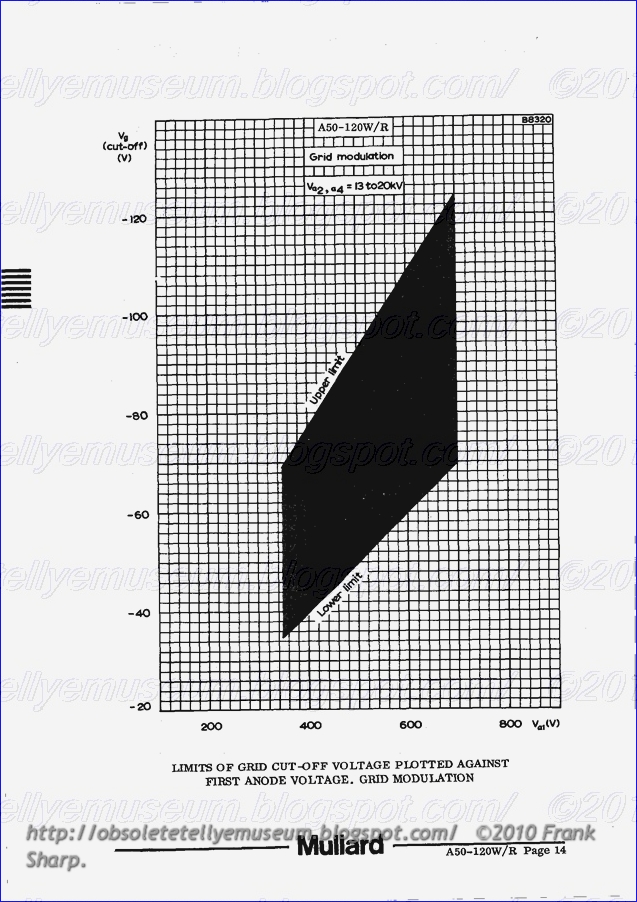
GBC MOD. 7319 CRT TUBE A50-120W.


TELEVISION TUBE A50- 120W/R

QUICK REFERENCE DATA

50cm (20in) direct viewing television tube With metal backed screen
and reinforced envelope. A separate safety screen is not required.
Suitable for use in receivers with push-through presentation. This
tube is fitted with a ring trap base:

Deflection angle 110 deg
Focusing Electrostatic
Light transmission (approx.) ’ ’ 45 %
Maximum overall length 319 mm

This data should be read in conjunction with GENERAL OPERATIONAL
RECOMMENDATIONS — TELEVISION PICTURE TUBES

HEATER
Suitable for series or parallel operation
Vh 6 . 3 V
Ib 300 mA

The limits of heater voltage and current are contained in ‘General
Operational Recommendations — Television Picture Tubes’.

Note - applies to series operation only

The surge heatervoltage must not exceed 9.5V r.m.s. when the supply is
switched on. A current limiting device maybe necessary in the circuit, to
ensure that this voltage is not exceeded.

OPERATING CONDITIONS
V 32’ £4 20 20 IN
V a3 (focus electrode control range) 0 to 400 0 to 400 V
V 400 500 V

a1Vg for visual extinction of focused raster -40 to -77 ~50 to -93 V

Vk for visual extinction of focused raster 36 to 66 45 to 80 V

For cathode modulation, all voltages are measured with respect to the
grid .

SCREEN (Metal backed)
Fluorescent colour White
Light transmission (EPPFOX-) 45 96


FOCUSING Electrostatic

The range of focus voltage shown in ‘Operating Conditions’ results in opti-
mum overall focus at a beam current of 250UA. In general, acceptable
resolution will be obtained with a fixed focus voltage.

DEFLECTION (Magnetic)

Diagonal deflection angle E 110 deg
Horizontal deflection angle 98 deg
Vertical deflection angle ' ' 81 ~ deg

The deflection coils should be designed to provide a pull—back of 4 .0mm
on a. nominal tube . '

CAPACITANCES
cg_au 7.0 pl?‘
ck_an 5.0 pF
ca2’.a4_M 850 to 1300; pF <- br="">"a2,a4-B 50° PF

EXTERNAL CONDUCTIVE COATING

This tube has an external conductive coating, M, and in accordance with
the General Operational Recommendations this should be connected directly
to pin 5 and not to chassis. The electrical connection to this coating must
be made within the area specifiedon the tube outline drawing.

 The capacitance of this coating to the final anode is used to provide smoothing for the
e.h.t. supply.


For flashover protection of the receiver, parallel spark gaps are included
for all the electrodes in the base of this tube, and the common connection
is made to pin 5. These spark gaps are intended as part of a system for
full flashover protection. A direct connection must always be made from
pin 5 to chassis, and the external conductive coating returned to chassis
only via pin 5, using short leads. Any electrode supplied directly from a
high energy source (such as the h.t. line) should be provided with a series
resistor.

RASTER CENTRING

See note under this heading in ‘General Operational Recommendations —
Television Picture Tubes‘.

Centring magnet field intensity . , 0 to 800 A/m

Maximum distance of centre of
centring field from reference line 57 mm

Adjustment of the centring magnet should not be such that ageneral reduc-
tion in brightness of the raster occurs .


TELEVISION TUBE MOUNTING POSITION

Any. The tube socket should not be rigidly motmted but should have
flexible leads and be allowed to move freely. The bottom circumference of the
base shell will fall within a circle of 40mm diameter which is centred on

the perpendicular from the centre of the face.

This tube is fitted with a pin protector in order to avoid damage to the

glass base due to bending of the base pins whilst handling the tube.

It is advisable tokeep this pin protector on the base imtil it can be replaced

by the socket after installation of the tube in any equipment.