Richtige Fernseher haben Röhren!

Richtige Fernseher haben Röhren!

In Brief: On this site you will find pictures and information about some of the electronic, electrical and electrotechnical Obsolete technology relics that the Frank Sharp Private museum has accumulated over the years .
Premise: There are lots of vintage electrical and electronic items that have not survived well or even completely disappeared and forgotten.

Or are not being collected nowadays in proportion to their significance or prevalence in their heyday, this is bad and the main part of the death land. The heavy, ugly sarcophagus; models with few endearing qualities, devices that have some over-riding disadvantage to ownership such as heavy weight,toxicity or inflated value when dismantled, tend to be under-represented by all but the most comprehensive collections and museums. They get relegated to the bottom of the wants list, derided as 'more trouble than they are worth', or just forgotten entirely. As a result, I started to notice gaps in the current representation of the history of electronic and electrical technology to the interested member of the public.

Following this idea around a bit, convinced me that a collection of the peculiar alone could not hope to survive on its own merits, but a museum that gave equal display space to the popular and the unpopular, would bring things to the attention of the average person that he has previously passed by or been shielded from. It's a matter of culture. From this, the Obsolete Technology Tellye Web Museum concept developed and all my other things too. It's an open platform for all electrical Electronic TV technology to have its few, but NOT last, moments of fame in a working, hand-on environment. We'll never own Colossus or Faraday's first transformer, but I can show things that you can't see at the Science Museum, and let you play with things that the Smithsonian can't allow people to touch, because my remit is different.

There was a society once that was the polar opposite of our disposable, junk society. A whole nation was built on the idea of placing quality before quantity in all things. The goal was not “more and newer,” but “better and higher" .This attitude was reflected not only in the manufacturing of material goods, but also in the realms of art and architecture, as well as in the social fabric of everyday life. The goal was for each new cohort of children to stand on a higher level than the preceding cohort: they were to be healthier, stronger, more intelligent, and more vibrant in every way.

The society that prioritized human, social and material quality is a Winner. Truly, it is the high point of all Western civilization. Consequently, its defeat meant the defeat of civilization itself.

Today, the West is headed for the abyss. For the ultimate fate of our disposable society is for that society itself to be disposed of. And this will happen sooner, rather than later.

OLD, but ORIGINAL, Well made, Funny, Not remotely controlled............. and not Made in CHINA.

How to use the site:
- If you landed here via any Search Engine, you will get what you searched for and you can search more using the search this blog feature provided by Google. You can visit more posts scrolling the left blog archive of all posts of the month/year,
or you can click on the main photo-page to start from the main page. Doing so it starts from the most recent post to the older post simple clicking on the Older Post button on the bottom of each page after reading , post after post.

You can even visit all posts, time to time, when reaching the bottom end of each page and click on the Older Post button.

- If you arrived here at the main page via bookmark you can visit all the site scrolling the left blog archive of all posts of the month/year pointing were you want , or more simple You can even visit all blog posts, from newer to older, clicking at the end of each bottom page on the Older Post button.
So you can see all the blog/site content surfing all pages in it.

- The search this blog feature provided by Google is a real search engine. If you're pointing particular things it will search IT for you; or you can place a brand name in the search query at your choice and visit all results page by page. It's useful since the content of the site is very large.

Note that if you don't find what you searched for, try it after a period of time; the site is a never ending job !

Every CRT Television saved let revive knowledge, thoughts, moments of the past life which will never return again.........

Many contemporary "televisions" (more correctly named as displays) would not have this level of staying power, many would ware out or require major services within just five years or less and of course, there is that perennial bug bear of planned obsolescence where components are deliberately designed to fail and, or manufactured with limited edition specificities..... and without considering........picture......sound........quality........
..............The bitterness of poor quality is remembered long after the sweetness of todays funny gadgets low price has faded from memory........ . . . . . .....
Don't forget the past, the end of the world is upon us! Pretty soon it will all turn to dust!

Have big FUN ! !
-----------------------
©2010, 2011, 2012, 2013, 2014 Frank Sharp - You do not have permission to copy photos and words from this blog, and any content may be never used it for auctions or commercial purposes, however feel free to post anything you see here with a courtesy link back, btw a link to the original post here , is mandatory.
All sets and apparates appearing here are property of Engineer Frank Sharp. NOTHING HERE IS FOR SALE !
All posts are presented here for informative, historical and educative purposes as applicable within Fair Use.


Friday, September 24, 2010

HOW TO REPLACE A BU808DFI LINE SCAN TRANSISTOR (LOT)

Vestel, Sanyo and Mivar and many others CRT TVs with a BU808DFI transistor installed in a horizontal scan are no longer included in the repair

https://blogger.googleusercontent.com/img/b/R29vZ2xl/AVvXsEjuwX3E5m1BNh15_aXndXpO3JFzyab2tZerco5TqQjhPwtgGBYgC4EXwr5R9g1FW4hIZU5QslI7aMfgdLBD31qIQYfSd-EnR8mloPEtb_nKKGmTgTyy3_e-90hDLb4_tLJG6djDZ-3zvWA/s1600/IMGH_06541__TVM.jpghttps://blogger.googleusercontent.com/img/b/R29vZ2xl/AVvXsEjmyVZikXdPzlRhAxP6QVN17By8Lc2h-tF6fygSsuuKXRCcrsdEq0kKbp2U6EbbmgspGnJBR5sL4_Pzd-MdiGsPjUbErH-T2ubyKxDoq-3VGUt8Y_WA-n4bP1ZC-r20lGviHnjSnf7jEAnR/s1600/IMGH_10010_DCE__TVM.jpg


WHY ?


Unfortunately, these transistors have long been absent from the free market. BU808DFX is nowhere to be found.

It should be noted that the analogue - 2SC5388, also became inaccessible. Counterfeits have appeared on sale, and the prices for this transistor are growing.

It is also not easy to find the original BU808DFH on sale, which has a smaller size and power, but can work fine in these TVs.


You can distinguish the original transistor from the fake one using an ohmmeter by measuring the resistance between terminals B and E. If there is less than 50 Ohm in both directions, it is re-labeled from some cheap one, but similar in body. The original multimeter will show the resistance between the base and the emitter, usually 200-300 ohms.

How to replace a composite transistor in a line scan?

This issue has been repeatedly discussed on forums and is relevant to this day.


I have tried and tested two options:

1. Installation of a functional analogue of two transistors.
2. Installation of 2SD2499 with some changes in the circuit.

Attention! Important Note: In most cases, the BU808 breakdown is caused by the electrolytic decoupling capacitor in the 10uFx63V driver.

It is necessary to replace it with a new one that has minimum active resistance loss (ESR). Capacitor quality is critical.
Sometimes a breakdown occurs due to the formation of an annular crack in the soldering of the OS connector of the line coils.

1. Functional analogue BU808 - in fact it is a composite Darlington transistor.
The internal structure is shown in the figure below:
BU808DFI


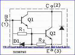
When using a line transistor (Q2 in the diagram) with a snubber diode and a resistor, for example 2SD2499, it remains to add three elements to the circuit - transistor Q1, as a current amplifier, as well as a resistor and a diode in its base.

The value of the resistor R1 is 270-330 ohms. You can take any diode D1 with a maximum current of 1 A, preferably a faster one, for example, the HER or UF series. Transistor Q1 is best used in a small package, for example BU1508AX, there is no need to attach it to the radiator.


The entire structure of three elements is mounted with a canopy and attached to the terminals of the second transistor (Q2), according to the connections and according to the scheme.
Q2 is screwed into place on the radiator. 

The conclusions of its collector and emitter are soldered into the standard contact pads.

This inclusion somewhat complicates the design, but does not change the circuit design. With proper and careful installation, excessive heating and other negative consequences are unlikely.


2. Installation of a bipolar transistor instead of a composite transistor is possible if a transistor with a sufficient current gain and good dynamic characteristics is used.
The original 2SD2499 was used for the experiments. Its fakes from unknown manufacturers, which are currently in widespread sale, do not work normally in this inclusion, they overheat within a few minutes. It is sometimes easy to distinguish a fake 2SD2499 from the original by the conclusions. The original one has thick tinned leads, while the counterfeit ones have flat ones, made of thin sheet steel.

Attention!
The replacement method was checked , but cannot be recommended to repairmen who do not have sufficient experience and theoretical knowledge.
Due to the fact that this replacement option is somewhat unreliable, contradicts the manufacturer's circuit design and can be implemented only with individual types and instances of line transistors, it cannot be considered and recommended in detail, in order to avoid negative consequences when it is used by unqualified craftsmen or TV owners.


The use of a transistor with sufficient current gain and good dynamic characteristics is a must.


HERE the Necessary modifications in case of using the original 2SD2499:

- The quality of the decoupling capacitor in the driver is critical.

The denomination 10uF 63Volt was changed by me to 47uF 63Volt Panasonic/Matshushita.
- Choke in the driver - short-circuit.
- Remove the standard BE 47 ohm resistor installed on the board.
- Install the BE diode, cathode to the base, anode to the body. Anything from 2A will do, preferably fast.

It is imperative to carry out temperature control.
Checked  on more than 20 TVs with crappy  Vestel 11AK30 chassis........SUCCESS !

The possibility of overheating is not excluded and depends on the properties of a particular transistor instance.


No comments:

Post a Comment

The most important thing to remember about the Comment Rules is this:
The determination of whether any comment is in compliance is at the sole discretion of this blog’s owner.

Comments on this blog may be blocked or deleted at any time.
Fair people are getting fair reply. Spam and useless crap and filthy comments / scrapers / observations goes all directly to My Private HELL without even appearing in public !!!

The fact that a comment is permitted in no way constitutes an endorsement of any view expressed, fact alleged, or link provided in that comment by the administrator of this site.
This means that there may be a delay between the submission and the eventual appearance of your comment.

Requiring blog comments to obey well-defined rules does not infringe on the free speech of commenters.

Resisting the tide of post-modernity may be difficult, but I will attempt it anyway.

Your choice.........Live or DIE.
That indeed is where your liberty lies.

Note: Only a member of this blog may post a comment.