


First Commodore monitor, the Commodore 1701 video monitor is introduced on 1983 Winter Consumer Electronics Show, Las Vegas, January 6-9................
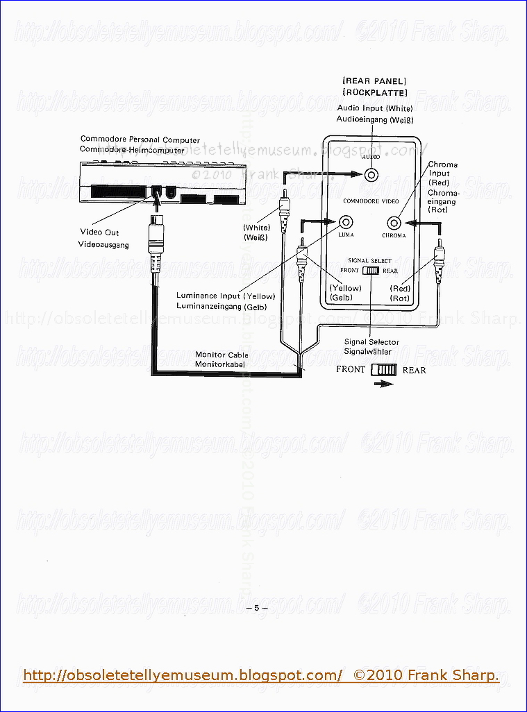
The COMMODORE MODEL NO. 1701 VIDEO MONITOR PAL system color TV ; 1701 and 1702 were 13-inch (33 cm) color monitors for the C64 which accepted as input either composite video or separate chrominance and luminance signals, similar to the S-Video standard, for superior performance with the C64 (or other devices capable of outputting a separated signal).
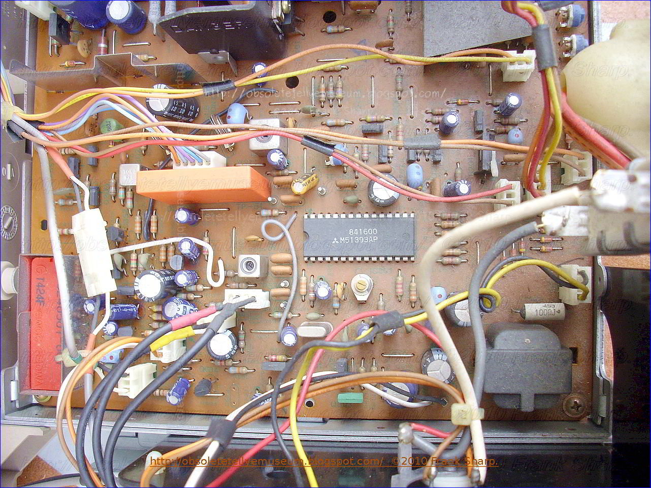
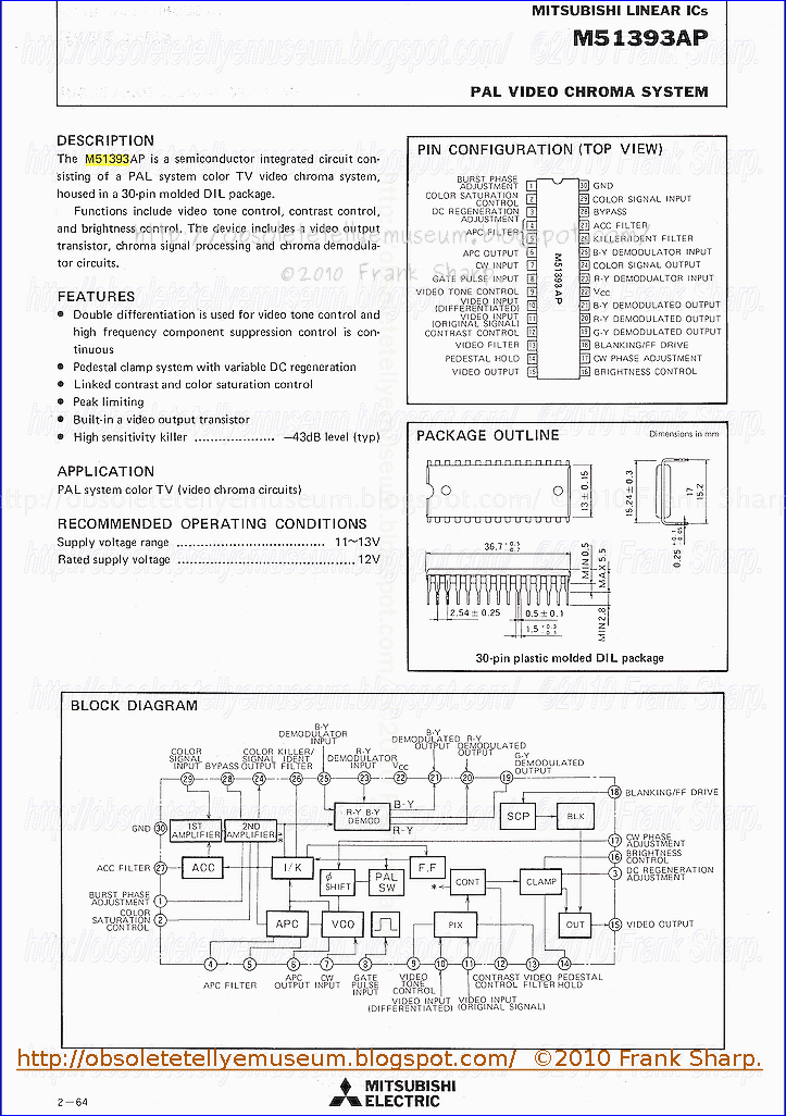
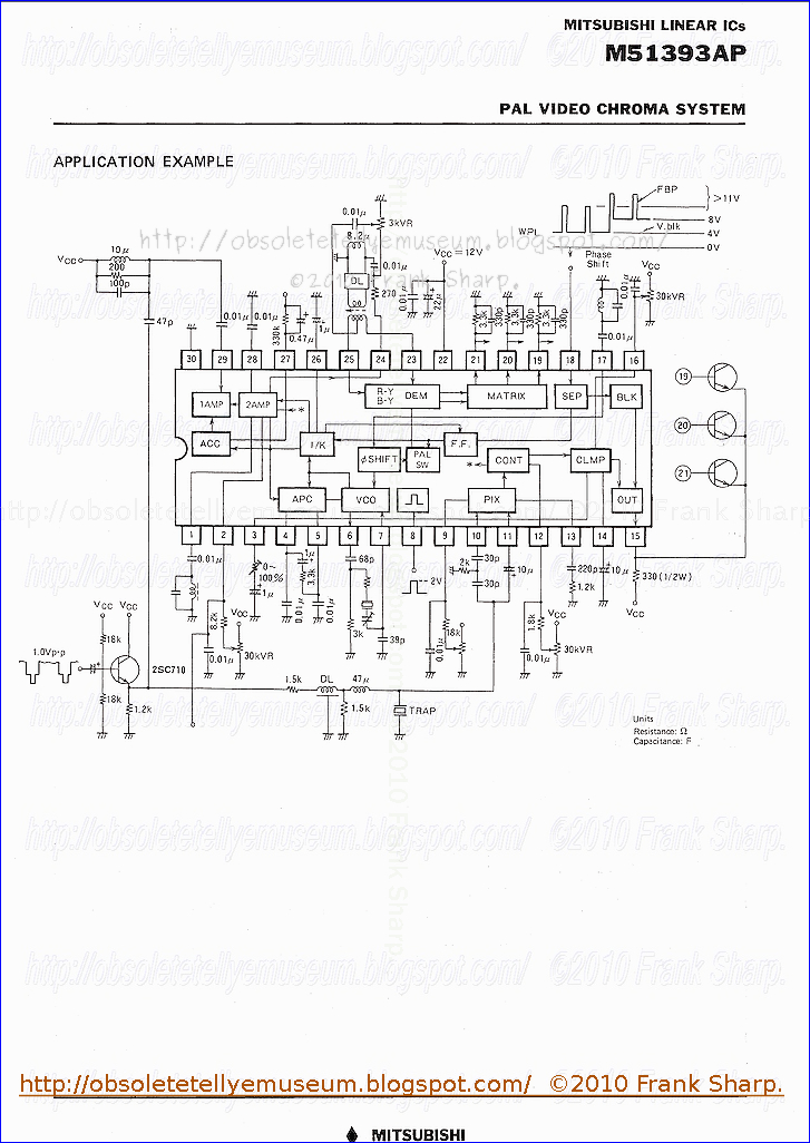
The monitor was developed in conjunction with a major television manufacturer , JVC , and includes special circuitry that greatly enhances picture resolution. Commodore even has applied for a patent on the new design, and features a first time a MITSUBISHI PAL decoder. the M51393AP is a semiconductor integrated circuit consisting of a PAL system color TV video chroma system, housed in a 30-pin molded dIL package.Functions include video tone control, contrast control,and brightness control. The device includes a video output transistor, chroma signal processing and chroma demodulator circuits.
The 1701 monitor has a composite input for the Vic 20, or for an even better picture for the C64, C16 and Plus 4, there is a chrominance and luminance output.
Although these peripherals came very late in the VIC-20's production history, they are worth mentioning because of their immense popularity among Commodore computer owners. Because of this, many VIC-20s were used with 1701 & 1702 monitors even after the VIC-20 had ceased being produced. Many present-day VIC-20 collectors and enthusiasts prefer to use this monitor because of its good quality picture, durability and versatility.
The 1701 and 1702 monitors are made to match the tan and brown colour theme of the Commodore 64. The only monitor known to have been designed specifically for use with the VIC-20 is Commodore's ultra-elusive VIC-1510 (which may not have been produced for sale).
The 1701 & 1702 monitors operate on the NTSC or PAL television standard. This means that any video player, video game or other source with A/V connectors can be used with these monitors. In fact, up until the recent advent of high-definition widescreen television, many amateur & professional film-makers sought out second-hand 1701/1702s to use as inexpensive monitors for use in video-editing suites. Perhaps these alternate uses explain why so many 1701/1702's were spared destruction in the period between the decline of 8-bit computers in the mid 1980s and the emergence of retro-computer collecting in the late 1990s.
The 1701 and 1702 monitors produce vivid colour and a good quality picture, but were not well-suited for displaying sharp text beyond 40 columns.
The square, charcoal-colored screen is framed in a black plastic rim at the top of the front panel of the box. Beneath the screen, on the right side of the front panel, is a grey power button. Beneath it are two jacks. The leftmost jack has a yellow plastic rim and is labeled "VIDEO". The rightmost jack has a white plastic rim and is labeled "AUDIO". There is a small, rectangular power indication light underneath the center of the screen. Beneath the screen on the left-hand side is a plastic strip that can be manually folded down revealing a row of monitor controls.
There are ventilation slits cut into the sides of the monitor. In the top, left-hand corner of the back panel of the monitor are additional Audio and Visual input jacks. There is also a switch for selecting either the front or the back input.
Commodore International (other names include Commodore International Limited and Commodore Business Machines) was an American home computer and electronics manufacturer founded by Jack Tramiel. Commodore International (CI), along with its subsidiary Commodore Business Machines (CBM), was a significant participant in the development of the home personal computer industry in the 1970s, 1980s and early 1990s. The company developed and marketed the world's best-selling computer, the Commodore 64 (1982), and released its Amiga computer line in July 1985. With quarterly sales ending 1983 of $49 million (equivalent to $109 million in 2020), Commodore was one of the world's largest personal computer manufacturers.
In 1954 Jack Tramiel founded Commodore as a typewriter repair service. Jack Tramiel was Polish, and after Auschwitz he traveled to the United States and joined the Army. After the army he decided to open a repair shop in the Bronx. Tramiel always had an inclination towards technology such as mechanical and electro-mechanical. Tramiel Moved again in 1955, this time to Ontario, Canada becoming a low-cost office furniture manufacturer.
In the 70’s there was a boom in the calculator and digital watches and although Tramiel ventured in this area in 1976 Commodore was on the edge of insolvency. Tramiel was saved by Irving Gould by lending him three million dollars and purchased MOS technologies. The acquisition was key to Tramiel’s philosophy of vertical integration. By production and distribution controlling, Commodore kept its costs very low and it’s products competitive. Commodore was again transferred to the Bahamas in order to take advantage of lower taxes, which eventually the company came on its feet again.
The headquarters and manufacturing base was in California. The idea in the 70’s was that the future of computers was in databases which were accessed via terminals. Desktop computers and affordable models were still a far reached idea. Tramiel refused to accept this. Determined as he was, in 1977 Commodore introduced the PET (Personal Electronic Transactor) which was designed by Chuck Paddle and it was sold at $795. By the time PET was put on the market there were other competitors such as Tandy TRS-80 and Apple II. Always keeping the idea of “User-Friendly” PET was composed of a Monitor, Keyboard and a Tape Drive which were housed in a plastic case.
Some References:
"The Commodore 64, that '80s computer icon, lives again". Retrieved November 17, 2014.
Mace, Scott (April 9, 1984). "Atarisoft vs. Commodore". InfoWorld. Vol. 6, no. 15. p. 50. Archived from the original on March 18, 2015. Retrieved February 4, 2015.
Johnston, Louis; Williamson, Samuel H. (2022). "What Was the U.S. GDP Then?". MeasuringWorth. Retrieved February 12, 2022. United States Gross Domestic Product deflator figures follow the Measuring Worth series.
"COMMODORE CORP reports earnings for Qtr to Dec 31". The New York Times. February 15, 1984.
"Commodore's History in the Adding Machine Business – Commodore International Historical Society". commodore.international. Retrieved July 1, 2022.
Bagnall, Brian (2006). On the Edge: The Spectacular Rise and Fall of Commodore, Variant Press. Page xiii. ISBN 0-9738649-0-7
Bagnall, Brian (2006). On the Edge: The Spectacular Rise and Fall of Commodore, Variant Press. Page 532. ISBN 0-9738649-0-7
"Might's Greater Toronto city directory, 1966". Internet Archive. 1966. Retrieved October 19, 2020.
"Calculator maker integrates downwards". New Scientist. Vol. 71, no. 1017. September 9, 1976. p. 541. ISSN 0262-4079. Archived from the original on March 18, 2015.
"Computer aus Zonenrandgebiet:: Commodore bald aus Braunschweig". computerwoche.de. Archived from the original on May 2, 2015. Retrieved July 12, 2015.
Hogan, Thom (August 31, 1981). "From Zero to a Billion in Five Years". InfoWorld. pp. 6–7. Archived from the original on March 1, 2017. Retrieved February 15, 2015.
Hogan, Thom (September 14, 1981). "State of Microcomputing / Some Horses Running Neck and Neck". pp. 10–12. Retrieved April 8, 2019.
Dickerman, Harold (August 1982). "The Commodore 8032 Business System". BYTE. p. 366. Archived from the original on March 15, 2016. Retrieved January 16, 2016.
West, Raeto Collin (1982). "Introduction and Overview". Programming the PET/CBM. Greensboro, North Carolina: Compute! Books. p. 1. ISBN 0-942386-04-3.
Bagnall, Brian (2006). On the Edge: The Spectacular Rise and Fall of Commodore, Variant Press. Page 221. ISBN 0-9738649-0-7
"RUN Magazine Issue 30 June 1986". June 1986. Archived from the original on March 11, 2016.
"Computer Commercial: Are You Keeping Up With Your Commodore (1983)(Commodore)(AU).mp4". Internet Archive. 1983. Archived from the original on March 22, 2016. Retrieved November 29, 2015.
Plus4world.com: Bil Herd: About the Commodore 16 prototype. Retrieved August 13, 2017
Mitchell, Peter W. (September 6, 1983). "A summer-CES report". Boston Phoenix. p. 4. Retrieved January 10, 2015.
Mace, Scott (February 27, 1984). "Can Atari Bounce Back?". InfoWorld. p. 100. Archived from the original on March 4, 2017. Retrieved January 18, 2015.
Leeman, Sheldon (May 1984). "The Future of Commodore?". Ahoy!. p. 44. Archived from the original on March 16, 2016. Retrieved June 27, 2014.
Perry, Tekla S.; Wallich, Paul (March 1985). "Design case history: the Commodore 64" (PDF). IEEE Spectrum. 22 (3): 48–58. doi:10.1109/MSPEC.1985.6370590. ISSN 0018-9235. S2CID 11900865. Archived (PDF) from the original on May 13, 2012. Retrieved November 12, 2011.
Kleinfield, N. R. (December 22, 1984). "Trading Up in Computer Gifts". The New York Times. Archived from the original on February 5, 2015. Retrieved February 5, 2015.
Garamszeghy, Mikos (1987). "Commodore in Europe: An International Comparison of Price and Availability" (PDF). The Transactor. Transactor Publishing. 7 (6): 21–23. Retrieved December 5, 2015.
"News BRK" (PDF). The Transactor. Transactor Publishing. 5 (2): 6–14. 1984. Retrieved January 1, 2015.
"News and New Products" (PDF). The Transactor. Canadian Micro Distributors. 4 (2): 4–9. 1983. Retrieved December 5, 2015.
Pollack, Andrew (January 14, 1984). "Founder of Commodore Resigns Unexpectedly". The New York Times. p. 27.
Anderson, John J. (March 1984). "Commodore". Creative Computing. p. 56. Archived from the original on April 5, 2015. Retrieved February 6, 2015.
Maher, Jimmy (July 28, 2013). "A Computer for Every Home?". The Digital Antiquarian. Archived from the original on July 11, 2014. Retrieved July 10, 2014.
Herzog, Marty (January 1988). "Neil Harris". Comics Interview. No. 54. Fictioneer Books. pp. 41–51.
(1985). Jack Tramiel Interview on YouTube
David Needle. "Special Report" p.90 Personal Computing, (August 1985)
"TOP SECRET: Confidential Atari-Amiga Agreement". Atari Historical Society. November 1981. Archived from the original on July 23, 2012. Retrieved July 23, 2006.
""Confidential Atari-Amiga Agreement" and "Afterthoughts: The Atari 1600XL Rumor"". Archives.atarimuseum.com. Archived from the original on April 15, 2009. Retrieved August 10, 2009.
Jay Miner
Osborne, Adam (April 13, 1981). "The Portable Osborne". InfoWorld. pp. 42–43. Archived from the original on March 18, 2015. Retrieved January 1, 2015.
Wierzbicki, Barbara (December 5, 1983). "Longevity of Commodore 64, VIC 20 questioned". InfoWorld. p. 24. Archived from the original on March 18, 2015. Retrieved January 13, 2015.
"Commodore's Back On Line, And Amiga's The Reason". Archived from the original on January 12, 2015.
"The Great Amiga Reboot". Archived from the original on January 12, 2015.
"1987 Commodore ad in InfoWorld targeted at dealers". October 26, 1987. Archived from the original on May 14, 2015.
Chin, Kathy (January 28, 1985). "Atari Promises Software For ST". InfoWorld. IDG. p. 17. Archived from the original on May 27, 2013. Retrieved March 19, 2011.
"OS/2's Arrival Marks the Dawn of a New Era". November 9, 1987. Archived from the original on May 14, 2015.
Dvorak, John C. (September 1985). "Image". Ahoy!. p. 5. Archived from the original on March 15, 2016. Retrieved June 27, 2014.
"Amiga: 25 Years Later". July 23, 2010. Archived from the original on January 1, 2015.
"Adios, Amiga?". Time. February 24, 1986. Archived from the original on December 4, 2011.
"The Maturation of Computer Entertainment: Warming The Global Village". Computer Gaming World. July 8, 1990. p. 11. Archived from the original on December 3, 2013. Retrieved November 16, 2013.
"Pay Went Up As Profits Plunged Proxy Reveals Big Salaries At Commodore". Archived from the original on January 12, 2015.
"Executive Benefits Questioned Commodore Hurting, But Officials Aren't". Archived from the original on January 12, 2015.
Ali's minimum $2 million annual combined salary and bonus will certainly earn him a place among the most richly rewarded technology company executives in the country.
"The Amiga Story: Conceived at Atari, Born at Commodore". Archived from the original on January 12, 2015.
Commodore began to falter in the early 90s as Windows PCs became more advanced. The multimedia features that wowed audiences in 1985 were commonplace in even inexpensive computers of the early 90s.
"What's hot: Amiga or Sega?". Archived from the original on January 12, 2015.
Still, Amiga owners could take consolation in the fact that their system played the best games around. But that's no longer the case. New videogame systems, NEC TurboGrafix, and SNK's NeoGeo--have surpassed the Amiga as a game machine. Another up-and-comer, the Nintendo SFX (known in Japan as the SuperFamicom), will blow it away. Meanwhile, after seven years the Amiga still has the same palette, the same eight sprites, and the same four audio voices.
"Taking the PC Plunge!". Archived from the original on December 28, 2014.
"A history of the Amiga Part 8: The demo scene". April 29, 2013. Archived from the original on July 4, 2017.
"MULTIMEDIA AND TELECOMMUNICATIONS, 1997-2002:PERSPECTIVES AND RECOMMENDATIONS".
"Looks great, Manny, but will it sell?". August 5, 1985. Archived from the original on May 14, 2015.
"PERIPHERALS; COMMODORE INTRODUCES NEW AMIGA". Archived from the original on October 23, 2016.
...as a new, untested machine from a company that has previously sold its products in toy stores, Amiga faces a tough challenge in cracking the conservative business market. Commodore officials vow that Amiga is the flagship of an armada of business products that will transform the company into a major international force in technology.
"RUN Magazine issue 42". June 1987. Archived from the original on April 3, 2016.
"A Multimedia Gem Commodore Is Dead. Long Live The Amiga. Suddenly, It's A Hot Item". Archived from the original on January 12, 2015.
David Pleasance, joint managing director of Commodore's United Kingdom subsidiary...
Tim Smith and Chris Lloyd (1994), "Chewing the Facts", 'Amiga Format' Annual 1994, 106-111, 107.
Maher, Jimmy (April 13, 2012). The Future Was Here: The Commodore Amiga. ISBN 9780262300742. Archived from the original on May 14, 2015.
"Natami Project Home Page". Archived from the original on January 18, 2015.
"Amiga Shopper Feb 1995". February 1995. Archived from the original on April 1, 2016.
"Forum / Interview / Rainer Benda". www.amigagadget.de. Retrieved June 21, 2020.
CTW August 16, 1993
Staff writer (December 27, 1993). "3D to make, distribute DOS-based Commodores". Computer Dealer News. Plesman Publications. 9 (26): 2 – via ProQuest.
Staff writer (April 20, 1994). "Commodore's financial woes leave it facing uncertain future". Computer Dealer News. Plesman Publications. 10 (8): 6 – via ProQuest.
Schofield, Jack (May 5, 1994). "Adios Amiga? Commodore is going into voluntary liquidation. Will its products survive?". The Guardian. Guardian Newspapers – via ProQuest.
Burgess, John (May 9, 1994). "Adios, Amiga and Commodore: From a Bang to a Whimper, PC Maker Closes Its Doors". The Washington Post. p. F17.
"Commodore Sinks". GamePro. No. 60. IDG. July 1994. p. 168.
Magee, Mike (July 1994). "Commodore International goes into voluntary liquidation". Personal Computer World. p. 214.
"Kidnapper's retro computer offers scant clues". TheGuardian.com. September 5, 2006. Archived from the original on April 16, 2017.
The beige-coloured machine was popular in the 1980s but is now considered an antique, though some electronic dance acts still use it and it has a cult following among some fans of retro computers.
"Ced Kurtz's Techman Texts: Andy's Amiga a cult computer favorite". Archived from the original on October 18, 2014.
Reimer, Jeremy (November 13, 2017). "A history of the Amiga, part 11: Between an Escom and a Gateway". Ars Technica. Retrieved June 21, 2020.
Reimer, Jeremy (November 13, 2017). "A history of the Amiga, part 11: Between an Escom and a Gateway". Ars Technica. Retrieved June 21, 2020.
Stets, Dan (April 22, 1995). "Escom Bid for Assets Triumphs over Dell: The German company doubled a $6.6 million bid for Commodore after Dell forced up the price". Philadelphia Inquirer. Philadelphia Media Network: C1 – via ProQuest.
"Commodore Auction Report". Archived from the original on March 3, 2016. Retrieved November 29, 2015.
"Tulip offloads Commodore brand". Retrieved November 29, 2015.
"Commodore International Corporation Changed Its Company Name to Reunite Investments, Inc". Reuters. June 24, 2009. Archived from the original on September 24, 2015.
"EDGAR Filing Documents for 0001457860-09-000002". Sec.gov. Archived from the original on October 15, 2012. Retrieved November 29, 2012.
C=Holdings BV v. Asiarim Corp. (United States District Court, Southern District of New York December 16, 2013).Text
Faillissements verslag Commodore Licensing B.V. Archived January 21, 2014, at the Wayback Machine
Nedfield Persbericht Archived February 2, 2014, at the Wayback Machine, Netherlands Authority for the Financial Markets, February 9, 2010
"Cloanto confirms transfers of Commodore/Amiga copyrights". amiga-news.de. Archived from the original on February 21, 2015. Retrieved February 20, 2015.
Braunschweiger Zeitung: Erinnerung an einen Konzern mit Weltruf, February 17, 2017
"Commodore calculator catalog" (PDF). Archived (PDF) from the original on July 14, 2014. Retrieved June 7, 2014.
"Commodore monitors". Gona.mactar.hu. Retrieved July 23, 2019.
"Computer Monitor". C64-Wiki. February 20, 2018. Retrieved July 23, 2019.
"Big Book of Amiga Hardware".


