


The Panasonic chassis Z1 is completely organized on one orizontal pcb board with all parts on it.
It has an uncommon parts placement in a semi diagonally mixed way starting from left to right.
Power Supply part is centrally placed, Line deflection + EHT on right side.
Signal part are left front placed, center side is the video part, bottom right is the microcontroller section placed.
Tuner + IF is upper left placed
It uses the TDA3562A (PHILIPS) as a Lum+Chrom combination but it doesn't implement the automatic cut-off function of it.
MICOM - MN14841
IR PREAMP - uPC1475HA
EAROM - MN1220T EAROM (Electrically Alterable ROM) 16bit, DIP-16.
The tuning voltage is supplied by TAHBX6270
The AN5071 is the integrated circuit incorporating TV tuner band-switch circuits and 31V-power-supply circuit.
The Panasonic Z I chassis was used in several 14, 16 and 21 in. models that were on sale during the years 1986-8. Models fitted with the chassis include the TC 1460, TC I465, TC 1470, TC 1475, TC 1665, TC 1675 and TC2175.The Z1 chassis is fairly complex , with everything under the control of an MN14841 microcomputer chip (IC1101). The self -oscillating chopper power supply STR55041N also provides mains isolation. IC101 (AN5150N) contains the i.f. circuitry and the timebase generators. A somewhat unusual chip is the TAHBX6267 (IC501) which produces the sandcastle pulses at pin 7, a mute output from a coincidence detector at pin 10, and an `X-ray protection' output at pin 12. This output is fed to pin 27 of IC101, where it shuts down the line oscillator in the event of excessive beam current or a shorted line output transformer - input sensing is at pin 13, via zener diode D502 for beam current and D510 for a line output transformer short.
Power Supply Circuit:
Fig. 1 shows the basic power supply circuit. The chopper transistor Q3 is within the STR55041N chip IC801. It's connected as a blocking oscillator, with feedback to its base (pin 2) from a secondary winding on the transformer (T801) via R81
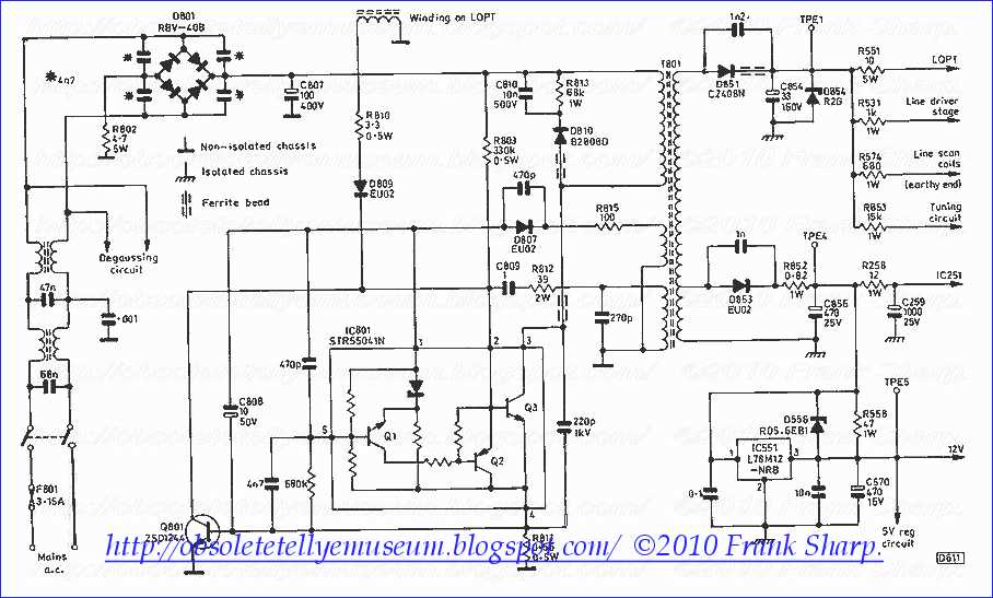 2 and C809. There are two other connections to pin 2. D809 feeds in pulses from a winding on the line output transformer to synchronise the operation of the chopper and line output stages. The other connection is to the collector of Q801, whose base senses the voltage across R811. This resistor is in series with the emitter of the chopper .transistor. In the event of excessive chopper current, the voltage across R811 rises and Q801 switches on, shorting out the input to the base of the chopper transistor. R803 supplies the chopper transistor with base bias, providing the start-up action and a discharge path for C809. D807 produces a negative voltage across C808. This voltage is applied to pin 1 of IC101 for regulation. Q1 is the error amplifier, comparing the fixed zener voltage at its emitter with the voltage produced at its base by a potential divider. Q1 's collector sets the voltage at the base of Q2, which in turn sets the d.c. conditions at the base of Q3.
No Life:
The first thing to do
is to check the chopper circuit outputs. There should be 103V at TPE1 and 16V at TPE4. If both voltages are missing, check the 3.15A mains fuse F801. If this is open -circuit, check the bridge rectifier diodes (D801) and the chopper chip (IC801) for shorts. If the fuse is o.k. and there are low output voltages from the power supply IC801 is probably faulty. Check it by replacement. Low h.t. voltage can be caused by the C2408N rectifier D851 being defective, its 33μF reservoir capacitor C854 being open -circuit or the R2G over -voltage protection diode D854 being leaky. If these items are all o.k., there's probably a fault in the line output stage. If the line output transformer T551 goes short-circuit the voltage at pin 6 (h.t. input) falls. This is communicated via the MA165 diode D510 to pin 13 of the TAHBX6267 chip IC501, which produces a high output at pin 12. This shuts down the line oscillator in IC101. If T551 is not short-circuit, the main possibilities are that the 2SD1439RL line output transistor Q551 is short-circuit or T551 has shorted turns. Intermittent fuse blowing can be caused by the degaussing posistor D805.A dead line output stage can also be caused by failure of the line driver stage. Check the driver transformer T531 for dry -joints then, if necessary, check whether the 11(12 feed resistor R531 or the 2SC1573AH driver transistor is open -circuit. There's an optocoupler (D811) in the power on/off circuitry in some models. If this is at fault there will be no operation. Also check, if necessary, Q1109 and the microcomputer chip IC1101. If the set is stuck in standby, check whether crystal X1101 is faulty or dry -jointed then suspect IC1101.
No Line Sync
For loss of line sync check whether C505 (4.7nF) or C506 (33nF) is short-circuit. If necessary check the associated components then replace IC101 (AN5150N).
Field Timebase faults
The field drive output from pin 26 of IC101 is fed to pin 4 of the AN5521 field driver/output chip IC451 via C467 (33μF, 25V) and R452 (18012). If the fault is field collapse, check the field oscillator waveform
at pin 24 of IC101 (AN5150N). If it's missing, check R401 (33k12), R402 (201(12 - field hold) and C401 (l pF) which could be short-circuit. If it's o.k., check for a field drive output at pin 26. Replace IC101 if it's missing. The first check in the field output stage should be for 24V at pin 7 of IC451. If the supply is missing, check D555 (EU02) and 8482 (TSF19631) which could be open -circuit, and C572 (2,200pF, 35V) which could be short-circuit. Then check whether there's an output waveform at pin 2. Replace IC451 if there is no waveform here. Other possibilities for field collapse are open -circuit scan coils (check at pins 4 and 2 of connector E4), R461 (3.312, 0.5W) which could be open -circuit and C458 (1,000pF, 35V) which could be short-circuit. For lack of height, check the values of R455 (15012) and R456 (50012 - height control). R456's carbon track could be faulty. The other things to check are diodes D455 (MR4270L) and D453 (MA700), by replacement if necessary.Picture Faults
Distorted picture: Check the voltage at pin 3 of IC101 (TPE9). The reading should be 4.5V. If it's incorrect, IC101 could be faulty, giving incorrect or no r.f. a.g.c. output. If the voltage is correct, check whether R104 (1M) is open -circuit or C14 (22pF, 16V) short-circuit. Double image/ringing effect: Check for dry -joints at the F1045A SAW filter X101. Resolder as necessary. Low contrast: Can be caused by an incorrect a.f.c. output from IC101 (AN5150N). If replacing IC101 doesn't provide a cure, check the components connected to pins 12, 13 and 14.
No Picture/Snowy Picture/Poor Sound
These symptoms can be caused by a faulty tuner. Check also that the receiver is tuning, and if so that it's memorising the channels. If this is not happening, check the TAHBX6289 memory protector chip IC1106. Check the voltages carefully. There should be 5V at pin 4. If this is missing or low, check whether D1112 (MA165) and/or C1130 (lpF, 50V) is open -circuit. Also ensure that the 5V series regulator transistor Q1105 (2SCI317) is operating correctly. The feed to its collector comes via R115 (1012) which could be open -circuit - this resistor also supplies the tuner's BU pin, via L18. If these points are in order, check that the -27V supply is present at pin 9 of the MN1220T memory chip IC1102. If this voltage is missing, check whether R552 (0.8212, 0.5W) or D553 (ERA22-04) is open -circuit and/or C563 (22pF, 50V) is short-circuit. A
lternatively R1165 (27012 safety) could be open -circuit. If the -27V supply is present, suspect ICI 102. Check it by replacement. Returning to the tuner, check that its 12V supply is present at pin 2 (BM). The tuner is type ENV -87455F1. If the 12V supply is missing, check the filter components: C19 (33pF, 16V) could be short-circuit and/or R12 (8.2(2, 0.5W) open -circuit. Alternatively the L78M12N I2V regulator chip IC551 could be faulty. It should produce 12V at pin 3. If it has no input at pin 1, check whether R852 (0.82S2, 1W) is open -circuit (this will remove the 16V supply at TPE4). If still in trouble, check that the r.f. a.g.c. control R102 (21d2) is set up correctly. Its carbon track could be dirty - check by replacement. If R102 is o.k., suspect the AN5150N i.f./timebase generator chip IC101. Check the pin voltages carefully. If necessary, check it by replacement. If the problem is tuning drift, D1118 (pPC574J) could be leaky. The tuning voltage is supplied by IC1104 (TAHBX6270). If there is no tuning, check whether its 33V supply is present at pin 3 -R1142 (100 safety) could be open -circuit. If loss of tuning or tuning drift is still the problem, check IC1104 by replacement.Colour Faults
No sync/colour smearing: Check that the amplitude of the sandcastle pulses at pin 7 of the TDA3562 colour decoder chip IC601 is correct. If the pulses are missing, suspect IC501 (TAHBX6267). If necessary, check it by replacement.
Loss of one colour: Check whether the relevant 2SC1473A output transistor is open -circuit - Q351 (green), Q352 (blue) and Q253 (red). Alternatively one of the 1.5kil, 0.5W flashover protection resistors could be open -circuit - R367 (green), 8366 (blue), R365 (red). The bases of the output transistors should be at about 3.3V. If this voltage is incorrect, check the associated MA165 diodes (D357 and D351 red, D356 and D352 blue, D355 and D353 green). D355/6/7 are in the switch -off spot suppression circuit, with Q356, while D351/2/3 with Q355 and Q354 provide on -screen displays. If everything is in order on the tube base panel, check the RGB outputs at pins 10 (red), II (green) and 12 (blue) of the TDA3565 colour decoder chip IC601. If necessary, check IC601 by replacement.
No colour: First check whether the 8.8MHz crystal X601 is dry -jointed or faulty (replace to test). Then check the waveforms at pins 13, 14 and 18 of th
e TDA3562 colour decoder chip IC601. Pin 18 provides the feed to the chroma delay line circuit, whose outputs are fed to pins 13 and 14. There could be a fault in the delay line DL601 or an associated component. Check that the sandcastle pulses are present at pin 7. If missing, check the continuity between pins 7 of IC601 and IC501 (TAHBX6267) which produces the sandcastle pulses. There could be a track break, R621 (2200) could be open -circuit or IC501 could be faulty. If all these points are in order, check IC501 by replacement.No/low Sound
The AN5265 audio amplifier chip IC251 should have a 16V supply at pin 9 and a 12V supply at pin 1. Check first that the 16V supply is present. If missing, check whether D853 (EU02), R852 (0.820, 1W) or R258 (120, 1W) is open -circuit. If D556 (RD5.6EB1) is short-circuit there will be no sound. If the 12V supply is missing, IC551 (L78M12N) could be faulty, R251 (1012 safety) open -circuit and/or C254 (100pF, 16V) short-circuit. If the supplies are o.k., suspect IC251. The cause of the problem could be IC101 (AN5150N), which produces a demodulated audio output at pin 11.
No Remote Control Operation
Some of the models that use the Z1 c
hassis feature remote control. If there is no remote control operation, check the handset - for poor battery connections and dry -joints to the LED and maybe the crystal. Worn touch pads can be a problem with the handset. Water damage is another possibility. Within the set, IC1105 (pPC1475HA) is the remote control receiver chip which is coupled to the MN14841 microcomputer chip IC1101. Problems here are minimal. Check that the I.t. supply is present at pin 9 of IC1105 - the reading should be about 5V. IC1105 can cause loss of remote control when faulty.Video chrominance and Luminance with TDA3562A,
TDA3562A
TDA3562A (Philips)PAL/NTSC ONE-CHIP DECODER, DESCRIPTION

The TDA3562A is a monolithic IC designed as
decode PAL and/or NTSC colour television standards
and it combines all functions required for the
identification and demodulation of PAL and NTSC
signals.
.CHROMINANCE SIGNAL PROCESSOR
.LUMINANCE SIGNAL PROCESSING WITH
CLAMPING
.HORIZONTAL AND VERTICAL BLANKING
.LINEAR TRANSMISSION OF INSERTED
RGB SIGNALS
.LINEAR CONTRAST AND BRIGHTNESS
CONTROL ACTING ON INSERTED AND MATRIXED
SIGNALS
.AUTOMATIC CUT-OFF CONTROL
.NTSC HUE CONTROL
FEATURES:
· A black-current stabilizer which
controls the black-currents of the
three electron-guns to a level low
enough to omit the black-level
adjustment
· Contrast control of inserted RGB
signals
· No black-level disturbance when
non-synchronized external RGB
signals are available on the inputs
· NTSC capability with hue control.
APPLICATIONS
· Teletext/broadcast antiope
Channel number display.
GENERAL DESCRIPTION
IIt follows that the external switches and filters which are required for the TDA3562A are not required for the TDA3566A. There is no difference between the amplitudes of the colour output signals in the PAL or NTSC mode. · The clamp capacitor at pins 10, 20 and 21 in the black-level stabilization loop can be reduced to 100 nF provided the stability of the loop is maintained. Loop stability depends on complete application. The clamp capacitors receive a pre-bias voltage to avoid coloured background during switch-on. · The crystal oscillator circuit has been changed to prevent parasitic oscillations on the third overtone of the crystal. Consequently the optimum tuning capacitance must be reduced to 10 pF.
The hue control has been improved (linear) .
CHROMINANCE SIGNALPROCESSOR
.LUMINANCE SIGNAL PROCESSING WITH CLAMPING
.HORIZONTAL AND VERTICAL BLANKING
.LINEAR TRANSMISSION OF INSERTED RGB SIGNALS
.LINEAR CONTRAST AND BRIGHTNESS CONTROL ACTING ON INSERTED AND MATRIXED SIGNALS
.AUTOMATIC CUT-OFF CONTROL .NTSC HUE CONTROL DESCRIPTION
The TDA3562A is a monolithic IC designed as decode PAL and/or NTSC colour television standards and it combines all functions required for the identification and demodulation of PAL and NTSC signals.
No comments:
Post a Comment
The most important thing to remember about the Comment Rules is this:
The determination of whether any comment is in compliance is at the sole discretion of this blog’s owner.
Comments on this blog may be blocked or deleted at any time.
Fair people are getting fair reply. Spam and useless crap and filthy comments / scrapers / observations goes all directly to My Private HELL without even appearing in public !!!
The fact that a comment is permitted in no way constitutes an endorsement of any view expressed, fact alleged, or link provided in that comment by the administrator of this site.
This means that there may be a delay between the submission and the eventual appearance of your comment.
Requiring blog comments to obey well-defined rules does not infringe on the free speech of commenters.
Resisting the tide of post-modernity may be difficult, but I will attempt it anyway.
Your choice.........Live or DIE.
That indeed is where your liberty lies.
Note: Only a member of this blog may post a comment.