

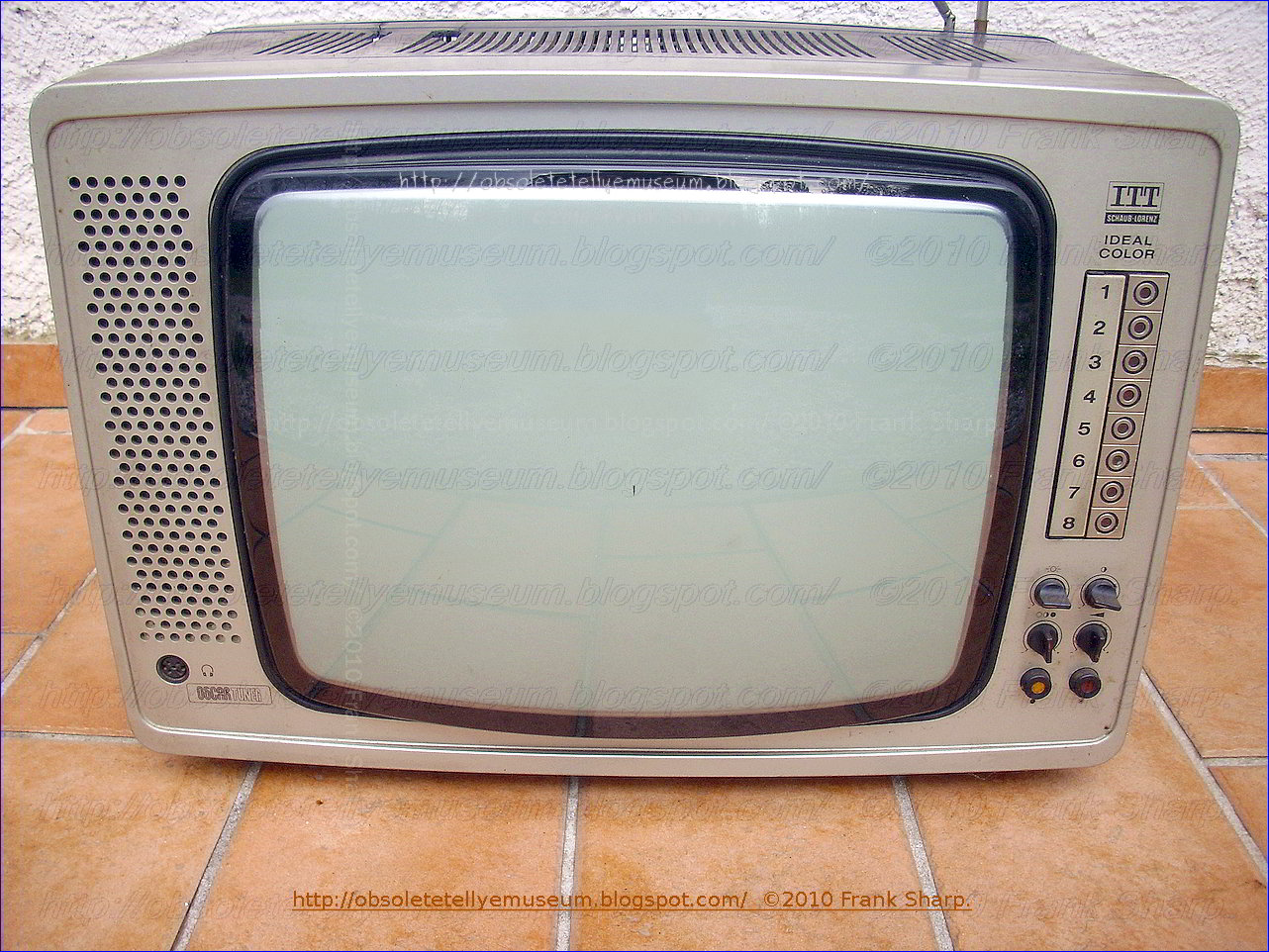


ITT IDEAL COLOR 1840X OSCAR 8 is a 18 inches portable heavy color television with manual potentiometric channel preselection 8 programs system and sensor program change.
- All commands are manually performed and front right placed.

- A DIN headphone jack is left side present.
- The set came in 1977 advertised as an all around house placeable tv color set for his versatility
The mechanical turret approach to television tuning has been used almost
exclusively for the past over 60 years. Even though replete with the
inherent disadvantages of mechanical complexity, unreliability and cost,
such apparatus has been technically capable of performing its intended
function and as a result the consumer has had to bear the burdens
associated with the device. However, with the " recent " Broadcast
demands for parity of tuning for UHF and VHF channels, the increasing
number of UHF and cable TV stations have imposed new tuning performance
requirements which severely tax the capability of the mechanical turret
tuner. Consequently, attempts are now being made to provide all
electronic tuning to meet the new requirements.
 The invention relates to a tuning unit with bandswitch for high
frequency receivers, especially radio and television receivers, having a
potentiometer system for the control of capacity diodes, the said
potentiometer system consisting of a plurality of parallel resistance
paths along which wiper contacts can be driven by means of screw
spindles disposed adjacent one another in a common insulating material
housing in which a bandswitch formed of metal rods is associated with
each tuning spindle.
The invention relates to a tuning unit with bandswitch for high
frequency receivers, especially radio and television receivers, having a
potentiometer system for the control of capacity diodes, the said
potentiometer system consisting of a plurality of parallel resistance
paths along which wiper contacts can be driven by means of screw
spindles disposed adjacent one another in a common insulating material
housing in which a bandswitch formed of metal rods is associated with
each tuning spindle.
In these tuning units, the working voltages of the capacity diodes in
the tuning circuits are recorded once a precise tuning to the desired
frequency has been performed. A potentiometer tuning system has great
advantages over the formerly used channel selectors operating with
mechanically adjustable capacitors (tuning condensers) or mechanically
adjustable inductances (variometers), mainly because it is not required
to have such great precision in its tuning mechanism.
Tuning units with bandswitches formed of variable resistances and
combined with interlocking pushbuttons controlling the supply of
recorded working voltages to capacity diodes are known. Channel
selection is accomplished by depressing the knobs, and the tuning or
fine tuning are performed by turning the knobs. The resistances serving
as voltage dividers in these tuning units are combined into a component
unit such that they are in the form of a ladderlike pattern on a common
insulating plate forming the cover of the housing in which the tuning
spindles and wiper contacts corresponding to the variable resistances
are housed. The number of resistances corresponds to the number of
channels or frequencies which are to be recorded. The wiper contact
picks up a voltage which, when applied to the capacity diodes determines
their capacitance and hence the frequency of the corresponding
oscillating circuit. The adjustment of the wipers is performed by
turning the tuning spindle coupled to the tuning knob. By the depression
of a button the electrical connection between a contact rod and a
tuning spindle is brought about and thus the selected voltage is applied
to the capacity diodes. Since the push buttons release one another, it
is possible simply by depressing another button to tune to a different
receiving frequency or a different channel, as the case may be.
For many years, mechanical turret tuners have been commonly employed in
television receivers to select the VHF channels and a second rotary or
continuous tuner has been used to select the UHF channels. For most
television receivers, this requires two different channel selection
knobs; and the tuners themselves are relatively bulky and require a
relatively large amount of space within the television receiver cabinet.
Because of the nature of these tuners, it also is necessary to locate
them directly behind the front level panel of the receiver, which
imposes significant restrictions on the cabinet design and the
arrangement of parts within the cabinet, reducing the flexibility of
design which would be possible if such tuners could be eliminated.
- It has a sensor keyboard for local commands, includes a plurality of tuning positions each defined by an adjustable potentiometer, a neon bulb indicator, a UHF/VHF switch and a two pole momentary contact touch switch. A common tuning capacitor has a tuning voltage developed thereacross for controlling the tuning of a varactor diode tuner. A source of reference potential is coupled across the tuning potentiometers and closure of any touch switch results in the tuning capacitor being charged from the voltage reference source through the selected one of the tuning potentiometers. The neon bulbs yield a visual indication of the selected tuning position. Circuitry for automatically placing control of the tuner to a preselected one of the tuning positions upon turn on of the receiver is also included.
"Recent" introduction (1970's) of several models featuring
touch-sensitive tuning is the culmination of a series of developments in
television tuning techniques over a long period of time. In the
earliest (66/67's) push-button tuner units (v.h.f.) tuning was effected
by the extent to which a multiple slug was inserted into the inline
signal and oscillator coils. This was an improvement over rotary types
of tuner and proved to be very reliable though the reset accuracy tended
to diminish after prolonged use. The earlier u.h.f. and integrated or
multiband tuners were also purely mechanical in operation and though the
designs were considerable technical achievements the push-buttons
nevertheless required quite some pressure to effect channel changing.
More recently (1970's) with the introduction of varicap tuners channel
changing has been done by electrical means. The capacitance of the
varicap diodes associated with each of the tuned circuits is altered by
changing the bias applied to them. For this a relatively simple switch
unit to select the appropriate potentiometer is all that is required.
The lightness of touch needed, elimination of mechanical switching
problems and the fact that the tuner can be mounted remote from the
switch at any convenient place in the cabinet give considerable design
advantages. Varicap tuners have also facilitated the application of
a.f.c., which is of particular importance in colour receivers. Basic
Principles Touch-sensitive control units form a welcome and natural
adjunct to the use of varicap tuner units. As they dispense completely
with the need for electrical switches and switch contacts they should
reduce further the number of service calls for tuning faults. Various
circuit arrangements are used in touch - operated tuner control units
but all operate when a finger tip bridges a pair of contacts which
incidentally look at first glance like a single contact. When the finger
tip completes the circuit forward bias is applied to a high gain
switching transistor. This in turn switches on another transistor or
transistors and the net outcome is that the supply to the appropriate
tuning potentiometer is connected and held on while the supply to the
previously selected potentiometer is switched off. In addition a channel
identfication bulb is usually brought into circuit. As skin resistance
is high the touch contacts must be incorporated in a correspondingly
high resistance circuit; in practice resistor values in the range
10-22Mohm are used. The switching operations are carried out either by
discrete transistors or i.c.s. Transistors form almost ideal switches of
course. In the absence of forward base bias the collector emitter
resistance they present is very high especially with silicon types
since there is negligible leakage current with these. On the other hand
when a transistor is biased fully on, i.e. is saturated or bottomed, the
collector current is maximum, the collector voltage minimum and the
collector emitter impedance is very little. There is very little
dissipation since although the collector current is at maximum the
collector emitter voltage is at minimum generally less than 1 Volt.
- Was first and last ITT(SEL) color television set using a special version of the "VIDOM CHASSIS" featuring a Horizontal deflection stage with Thyristors circuits.
- Horizontal Beam Deflection and high voltage generating circuits realized with Thyristors circuits.
 ation
in the ITT circuit. however is the use of thyristors in the line
timebase (see Fig. 3). This type of circuit was originated by RCA in
America and has been successfully used in over half a million RCA colour
sets since 1968. The great advantages of the circuit are its relative
simplicity (for a 110° timebase), its efficiency and reliability
thyristors as used in this circuit are immune to picture tube flashover
and to almost any fault condition which might occur (such as
short-circuited scan coils). Receiver manufacturers are thus faced with
two basic alternatives and the final decision will take into account
simplicity, reliability and cost. At first sight the ITT circuit appears
to be the more attractive proposition but it must be pointed out that
the narrow - neck tube is not entirely proven and due to the
miniaturisation of the electron -gun assembly there may be cause to
suspect its reliability. Nonetheless it seems likely that thyristors
will be widely used in both colour and monochrome timebases in the years
to come so it is worthwhile understanding how they work.
ation
in the ITT circuit. however is the use of thyristors in the line
timebase (see Fig. 3). This type of circuit was originated by RCA in
America and has been successfully used in over half a million RCA colour
sets since 1968. The great advantages of the circuit are its relative
simplicity (for a 110° timebase), its efficiency and reliability
thyristors as used in this circuit are immune to picture tube flashover
and to almost any fault condition which might occur (such as
short-circuited scan coils). Receiver manufacturers are thus faced with
two basic alternatives and the final decision will take into account
simplicity, reliability and cost. At first sight the ITT circuit appears
to be the more attractive proposition but it must be pointed out that
the narrow - neck tube is not entirely proven and due to the
miniaturisation of the electron -gun assembly there may be cause to
suspect its reliability. Nonetheless it seems likely that thyristors
will be widely used in both colour and monochrome timebases in the years
to come so it is worthwhile understanding how they work. It's a very good system to use where the line scan coils require large
peak currents with only a moderate flyback voltage an intrinsic
characteristic of toroidally wound deflection coils. The basic thyristor
line output stage arrangement used in all these chassis is shown in
Fig. 1
It's a very good system to use where the line scan coils require large
peak currents with only a moderate flyback voltage an intrinsic
characteristic of toroidally wound deflection coils. The basic thyristor
line output stage arrangement used in all these chassis is shown in
Fig. 1it was originally devised by RCA. Many sets fitted with 110°, narrow -neck delta -gun tubes used a thyristor line output stage - for example those in the Grundig and Saba ranges and the Finlux Peacock , Indesit, Siemens, Salora, Metz, Nordmende, Blaupunkt, ITT, Seleco, REX, Mivar, Emerson, Brionvega, Loewe, Galaxi, Stern, Zanussi, Wega, Philco. The circuit continued to find favour in earlier chassis designed for use with in -line gun tubes, examples being found in the Grundig and Korting ranges - also, Indesit, Siemens, Salora, Metz, Nordmende, Blaupunkt, ITT, Seleco, REX, Mivar, Emerson, Brionvega, Loewe, Galaxi, Stern, Zanussi, Wega, Philco the Rediffusion Mk. III chassis. Deflection currents of up to 13A peak -to -peak are commonly encountered with 110° tubes, with a flyback voltage of only some 600V peak to peak. The total energy requirement is of the order of 6mJ, which is 50 per cent higher than modern 110° tubes of the 30AX and S4 variety with their saddle -wound line scan coils. The only problem with this type of circuit is the large amount of energy that shuttles back and forth at line frequency. This places a heavy stress on certain components. Circuit losses produce quite high temperatures, which are concentrated at certain points, in particular the commutating combi coil. This leads to deterioration of the soldered joints around the coil, a common cause of failure. This can hav
 e
a cumulative effect, a high resistance joint increasing the local
heating until the joint becomes well and truly dry -a classic symptom
with some Grundig / Emerson sets. The wound components themselves can be
a source of trouble, due to losses - particularly the combi coil and
the regulating transductor. Later chassis are less prone to this sort of
thing, partly because of the use of later generation, higher efficiency
yokes but mainly due to more generous and better design of the wound
components. The ideal dielectric for use in the tuning capacitors is
polypropylene (either metalised or film). It's a truly won- derful
dielectric - very stable, with very small losses, and capable of
operation at high frequencies and elevated temperatures. It's also
nowadays reasonably inexpensive. Unfortunately many earlier chassis of
this type used polyester capacitors, and it's no surprise that they were
inclined to give up. When replacing the tuning capacitors in a
thyristor line output stage it's essential to use polypropylene types -a
good range of axial components with values ranging from 0.001µF to
047µF is available from RS Components, enabling even non-standard values
to be made up from an appropriate combination. Using polypropylene
capacitors in place of polyester ones will not only ensure capacitor
reliability but will also lower the stress on other components by
reducing the circuit losses (and hence power consumption).
e
a cumulative effect, a high resistance joint increasing the local
heating until the joint becomes well and truly dry -a classic symptom
with some Grundig / Emerson sets. The wound components themselves can be
a source of trouble, due to losses - particularly the combi coil and
the regulating transductor. Later chassis are less prone to this sort of
thing, partly because of the use of later generation, higher efficiency
yokes but mainly due to more generous and better design of the wound
components. The ideal dielectric for use in the tuning capacitors is
polypropylene (either metalised or film). It's a truly won- derful
dielectric - very stable, with very small losses, and capable of
operation at high frequencies and elevated temperatures. It's also
nowadays reasonably inexpensive. Unfortunately many earlier chassis of
this type used polyester capacitors, and it's no surprise that they were
inclined to give up. When replacing the tuning capacitors in a
thyristor line output stage it's essential to use polypropylene types -a
good range of axial components with values ranging from 0.001µF to
047µF is available from RS Components, enabling even non-standard values
to be made up from an appropriate combination. Using polypropylene
capacitors in place of polyester ones will not only ensure capacitor
reliability but will also lower the stress on other components by
reducing the circuit losses (and hence power consumption).Numerous circuit designs for completely transistorized television receivers either have been incorporated in commercially available receivers or have been described in detail in various technical publications. One of the most troublesome areas in such transistor receivers, from the point of View of reliability and economy, lies in the horizontal deflection circuits.
As an attempt to avoid the voltage and current limitations of transistor deflection circuits, a number of circuits have been proposed utilizing the silicon controlled rectifier (SCR), a semiconductor device capable of handling substantially higher currents and voltages than transistors.
The circuit utilizes two bi-directionally conductive switching means which serve respectively as trace and commutating switches. Particularly, each of the switching means comprises the parallel combination of a silicon controlled rectifier (SCR) and a diode. The commutating switch is triggered on shortly before the desired beginning of retrace and, in conjunction with a resonant commutating circuit having an inductor and two capacitors, serves to turn off the trace switch to initiate retrace. The commutating circuit is also arranged to turn oft the commutating SCR before the end of retrace.
 ALL
colour television receivers in yr 1971's production in the European
continent were employing a shadowmask tube with a deflection angle of
90°. The manufacturers of colour tubes have however in their wisdom
decided to develop 110 tubes, on the grounds that the increase in
complexity of the scanning requirements for such tubes is more than
justified by the resultant saving in cabinet depth even though this
saving is only of the order of a few inches. It is of increase in the
deflection angle will make the precise control of the three electron
beams more difficult, thus increasing the scanning, convergence, purity
and focusing errors.
ALL
colour television receivers in yr 1971's production in the European
continent were employing a shadowmask tube with a deflection angle of
90°. The manufacturers of colour tubes have however in their wisdom
decided to develop 110 tubes, on the grounds that the increase in
complexity of the scanning requirements for such tubes is more than
justified by the resultant saving in cabinet depth even though this
saving is only of the order of a few inches. It is of increase in the
deflection angle will make the precise control of the three electron
beams more difficult, thus increasing the scanning, convergence, purity
and focusing errors. To add to the general confusion in this field at present there are two different 110' systems, backed by Philips and ITT respectively, which are contending for the grand prize of acceptance by the receiver manufacturers.
The loser in this contest will be in a sorry state indeed. Philips are advocating the use of a wide neck 110' tube ("wide neck" in this connection means that the tube neck and the electron gun dimensions are the same as in a 90° tube) with saddle yoke scan coils and a single transistor line output stage. This system suffers from several disadvantages. The saddle yoke scan coils are of the type used in monochrome receivers. with the windings "flared" up the bowl of the tube and therefore not likely to give very precise scanning. Due to the design of the tube and the scan coils highly complex dynamic convergence circuitry was required : while a few potentiometers and variable inductors are sufficient to achieve convergence on a 90' tube, on this thick -neck
type of 110 ° tube it is necessary to incorporate transistors in the convergence circuitry and extra controls for corner convergence. Furthermore the potential required to focus the tube varies considerably over the scanning range so that dynamic focus circuitry is necessary imagine the problems involved in varying the 5kV focus potential at line rate! The desirable feature of the Philips 110° time base circuitry was the simplicity of the line output stage which employs a single transistor and is said to be more reliable than earlier two -transistor circuits. ITT's approach to the problem was altogether different and was shown in earlier apparates. A narrow neck 110° tube is used (type A51 -190X), the neck of this being little larger than that of a conventional 100° monochrome tube. Miniature, closely spaced electron guns are incorporated in this and thus the three electron beams are closer together from the very start and require less convergence in fact a relatively simple passive convergence circuit can be used. To ensure that the scanning is precisely controlled a new type of deflection yoke is employed. The construction of this is toroidal (see Fig. 1) and both the line and field coils are similarly wound on it. At first sight the ITT circuit appears to be the more attractive proposition but it must be pointed out that the narrow neck tube was not entirely proven and due to the miniaturisation of the electron -gun assembly there may be cause to suspect its reliability (indeed).
Nonetheless it seems likely that thyristors will be widely used in both colour and monochrome timebases in the further 70's years so it is worthwhile understanding how they work under the obsolete technology aspect ; see above.
-
 The set is build with a Modular chassis design because as modern television receivers become more complex the problem of
repairing the receiver becomes more difficult. As the number of
components used in the television receiver increases the susceptibility
to breakdown increases and it becomes more difficult to replace
defective components as they are more closely spaced. The problem has
become even more complicated with the increasing number of color
television receivers in use. A color television receiver has a larger
number of circuits of a higher degree of complexity than the black and
white receiver and further a more highly trained serviceman is required
to properly service the color television receiver.
The set is build with a Modular chassis design because as modern television receivers become more complex the problem of
repairing the receiver becomes more difficult. As the number of
components used in the television receiver increases the susceptibility
to breakdown increases and it becomes more difficult to replace
defective components as they are more closely spaced. The problem has
become even more complicated with the increasing number of color
television receivers in use. A color television receiver has a larger
number of circuits of a higher degree of complexity than the black and
white receiver and further a more highly trained serviceman is required
to properly service the color television receiver.

Even with the great majority of the color television receiver malfunctions being of the "easy to find and repair" type proper servicing of color sets has been difficult to obtain due to the shortage of trained serviceman.
At the present time advances in the state of the semiconductor art have led to the increasing use of transistors in color television receivers. The receiver described in this application has only two tubes, the picture tube and the high voltage rectifier tube, all the other active components in the receiver being semiconductors.
One important characteristic of a semiconductor device is its extreme reliability in comparison with the vacuum tube. The number of transistor and integrated circuit failures in the television receiver will be very low in comparison with the failures of other components, the reverse of what is true in present day color television receivers. Thus most failures in future television receivers will be of the hard to service type and will require more highly qualified servicemen.
The primary symptoms of a television receiver malfunction are shown on the picture tube of the television receiver while the components causing the malfunction are located within the cabinet. Also many adjustments to the receiver require the serviceman to observe the screen. Thus the serviceman must use unsatisfactory mirror arrangements to remove the electronic chassis from the cabinet, usually a very difficult task. Further many components are "buried" in a maze of circuitry and other components so that they are difficult to remove and replace without damage to other components in the receiver.
Repairing a modern color television receiver often requires that the receiver be removed from the home and carried to a repair shop where it may remain for many weeks. This is an expensive undertaking since most receivers are bulky and heavy enough to require at least two persons to carry them. Further, two trips must be made to the home, one to pick up the receiver and one to deliver it. For these reasons, the cost of maintaining the color television receiver in operating condition often exceeds the initial cost of the receiver and is an important factor in determining whether a receiver will be purchased.
Therefore, the object of this invention is to provide a transistorized color television receiver in which the main electronic chassis is easily accessible for maintenance and adjustment. Another object of this invention is to provide a transistorized color television receiver in which the electronic circuits are divided into a plurality of modules with the modules easily removable for service and maintenance. The main electronic chassis is slidably mounted within the cabinet so that it may be withdrawn, in the same manner as a drawer, to expose the electronic circuitry therein for maintenance and adjustment from the rear closure panel after easy removal. Another aspect is the capability to be serviced at eventually the home of the owner.
- This chassis was even fitted in table models and was produced only in 1977.
-
ITT Corporation (NYS E:
ITT) is a global diversified manufacturing company with 2008
revenues of $11.7 billion. ITT participates in global markets including
water and fluids management, defense and security, and motion and
flow control. Forbes.com named ITT Corporation to its list of
"America's Best Managed Companies" for 2008, and awarded the company
the top spot in the conglomerates category.
E:
ITT) is a global diversified manufacturing company with 2008
revenues of $11.7 billion. ITT participates in global markets including
water and fluids management, defense and security, and motion and
flow control. Forbes.com named ITT Corporation to its list of
"America's Best Managed Companies" for 2008, and awarded the company
the top spot in the conglomerates category.
,ITT's
water business is the world's largest supplier of pumps and systems
to transport, treat and control water, and other fluids. The
company's defense electronics and services business is one of the ten
largest US defense contractors providing defense and security
systems, advanced technologies and operational services for military
and civilian customers. ITT's motion and flow control business
manufactures specialty components for aerospace, transportation and
industrial markets.
In 2008, ITT was named to the
Dow Jones Sustainability World Index (DJSI World) for the tenth time
in recognition of the company's economic, environmental and social
performance. ITT is one of the few companies to be included on the
list every year since its inception in 1999.
The
company was founded in 1920 as International Telephone &
Telegraph. During the 1960s and 1970s, under the leadership of its
CEO Harold Geneen the company rose to prominence as the archetypal
conglomerate, deriving its growth from hundreds of acquisitions in
diversified industries. ITT divested its telecommunications assets in
1986, and in 1995 spun off its non-manufacturing divisions, later to
be purchased by Starwood Hotels & Resorts Worldwide.
In 1996, the company became ITT Industries, Inc., but changed its name back to ITT Corporation in 2006.
 History
ITT
was formed in 1920, created from the Puerto Rico Telephone Company
co-founded by Sosthenes Behn.[1] Its first major expansion was in 1923
when it consolidated the Spanish Telecoms market into what is now
Telefónica.[2] From 1922 to 1925 it purchased a number of European
telephone companies. In 1925 it purchased the Bell Telephone
Manufacturing Company of Brussels, Belgium, which was formerly
affiliated with AT&T, and manufactured rotary system switching
equipment. In the 1930s, ITT grew through purchasing German electronic
companies Standard Elektrizitaetsgesellschaft (SEG) and Mix
& Genest, both of which were internationally active
companies. Its only serious rival was the Theodore Gary &
Company conglomerate, which operated a subsidiary, Associated
Telephone and Telegraph, with manufacturing plants in Europe.
In
the United States, ITT acquired the various companies of the Mackay
Companies in 1928 through a specially organized subsidiary
corporation, Postal Telegraph & Cable. These companies
included the Commercial Cable Company, the Commercial Pacific Cable
Company, Postal Telegraph, and the Federal Telegraph Company.
International telecommunications
International
telecommunications manufacturing subsidiaries included STC in
Australia and Britain, SEL in Germany, BTM in Belgium, and CGCT and LMT
in France. Alec Reeves invented Pulse-code modulation (PCM), upon
which future digital voice communication was based. These companies
manufactured equipment according to ITT designs including the (1960s)
Pentaconta crossbar switch and (1970s) Metaconta D, L and 10c Stored
Program Control e xchanges,
mostly for sale to their respective national telephone
administrations. This equipment was also produced under license in
Poznań (Poland), and in Yugoslavia, and elsewhere. ITT was the
largest owner of the LM Ericsson company in Sweden but sold out in
1960.
xchanges,
mostly for sale to their respective national telephone
administrations. This equipment was also produced under license in
Poznań (Poland), and in Yugoslavia, and elsewhere. ITT was the
largest owner of the LM Ericsson company in Sweden but sold out in
1960.
1989 breakup
In
1989 ITT sold its international telecommunications product
businesses to Alcatel, now Alcatel-Lucent. ITT Kellogg was also part
of the 1989 sale to Alcatel. The company was then sold to private
investors in the U.S. and went by the name Cortelco Kellogg. Today
the company is known as Cortelco (Corinth Telecommunications
Corporation, named for Corinth, MS headquarters). ITT Educational
Services, Inc. (ESI) was spun off through an IPO in 1994, with ITT as
an 83% shareholder. ITT merged its long distance division with
Metromedia Long Distance, creating Metromedia-ITT. Metromedia-ITT
would eventually be acquired by Long Distance Discount Services, Inc.
(LDDS) in 1993. LDDS would later change its name to Worldcom in
1995.
In 1995, ITT Corporation split into 3 separate public companies:
*
ITT Corp. — In 1997, ITT Corp. completed a merger with Starwood
Hotels & Resorts Worldwide, selling off its non-hotel and
resorts business. By 1999, ITT completely divested from ITT/ESI;
however, the schools still operate as ITT Technical Institute using
the ITT name under license.[1] Also in 1999, ITT Corp. dropped the
ITT name in favor of Starwood.[7]
* ITT Hartford (insurance) —
Today ITT Hartford is still a major insurance company although it has
dropped the ITT from its name altogether. The company is now known
as The Hartford Financial Services Group, Inc.
* ITT Industries — ITT operated under this name until 2006 and is a major manufacturing and defense contractor business.
o On July 1, 2006, ITT Industries changed its name to ITT Corporation as a result of its shareholders vote on May 9, 2006.
Purchase of International Motion Control (IMC)
An
agreement was reached on June 26, 2007 for ITT to acquire privately
held International Motion Control (IMC) for $395 million. The deal
was closed and finalized in September 2007. An announcement was made
September 14, 2010, to close the Cleveland site.
Purchase of EDO
An
agreement was reached September 18, 2007 for ITT to buy EDO
Corporation for $1.7 billion.[12] After EDO shareholders' approval, the
deal was closed and finalized on December 20, 2007.
Purchase of Laing
On
April 16, 2009, ITT announced it has signed a definitive agreement
to acquire Laing GmbH of Germany, a privately held leading producer
of energy-efficient circulator pumps primarily used in residential
and commercial plumbing and heating, ventilating and air conditioning
(HVAC) systems.
2011 breakup
On
January 12, 2011, ITT announced a transformation to separate the
company into 3, stand-alone, publicly-traded, and independent companies.
HISTORY OF Standard Elektrik Lorenz AG IN GERMAN:
Die
Standard Elektrik Lorenz AG (heute Alcatel-Lucent Deutschland
AG) ist ein Unternehmen der Nachrichtentechnik (früherer Slogan:
SEL – Die ganze Nachrichtentechnik) mit Hauptsitz in
Stuttgart. Zur Nachrichtentechnik zählen auch Informations- und
Kommunikationstechnik, Telekommunikationstechnik (SEL war für
die Röchelschaltung bekannt) und früher Fernmeldetechnik oder
Schwachstromtechnik. Einen weiteren Geschäftsbereich hatte das
Unternehmen in der Bahnsicherungstechnik, so wurden für die
Deutsche Bundesbahn Relaisstellwerke und elektronische Stellwerke
mit den dazugehörigen Außenanlagen (Signale,
Gleisfreimeldeanlagen, Weichenantriebe) sowie die
Linienzugbeeinflussung entwickelt und gebaut, welche auch bei
ausländischen Bahnen Abnehmer fanden. Der Bereich gehört seit 2007
als Thales Transportation Systems GmbH (seit 02.2011 vorher
Thales Ra il
Signalling Solutions GmbH) zum Thales-Konzern. Die bereits 1998
ausgegliederten Bereiche Alcatel Air Navigation Systems und SEL
Verteidigungssysteme sind ebenfalls heute in Thales
Deutschland beheimatet.[1]
il
Signalling Solutions GmbH) zum Thales-Konzern. Die bereits 1998
ausgegliederten Bereiche Alcatel Air Navigation Systems und SEL
Verteidigungssysteme sind ebenfalls heute in Thales
Deutschland beheimatet.[1]
Fernseher Illustraphon 743 von 1957
„Goldsuper Stereo 20“ (1961)
Das Flaggschiff der erfolgreichen Schaub-Lorenz Kofferradios der sechziger Jahre: Touring 70 Universal
Erster Digitalfernseher der Welt (1983)
Bis
1987 gehörte SEL zusammen mit anderen auf dem Sektor
Telekommunikation in anderen Ländern tätigen Schwesterfirmen zum
US-amerikanischen Mischkonzern International Telephone and Telegraph
(ITT). ITT verkaufte die Aktien-Mehrheit an den
ITT-Telekommunikationsfirmen an die französische Compagnie Générale
d’Electricité (CGE), die nach der Zusammenfassung mit den eigenen
Telekommunikationsaktivitäten daraus die Alcatel N.V. bildete.
Die
Standard Elektrik Lorenz AG wurde 1993 in Alcatel SEL AG
umbenannt. Die Aktienmehrheit liegt mit über 99 % bei der Alcatel.
Mit der Fusion von Alcatel und Lucent zu Alcatel-Lucent am 1.
Dezember 2006 und der Neu-Firmierung beider Unternehmen in
Deutschland zur Alcatel-Lucent Deutschland AG entfiel der Zusatz
SEL.
Geschichte
Die
beiden Stammfirmen des Unternehmens, die Mix & Genest AG und
die Telegraphenbauanstalt von C. Lorenz, wurden 1879 bzw. 1880
gegründet. Das erste Patent von Mix & Genest datiert
von 1883, das erste Patent von C. Lorenz ist aus dem Jahr 1902.
Das
Unternehmen Mix & Genest war wesentlicher Teil der
Standard Elektrizitäts-Gesellschaft (SEG), in die auch die
Süddeutsche Apparatefabrik (SAF), die 1875 von F. Heller als
"Friedrich Heller, Fabrik Elektrotechnischer Apparate"
gegründet wurde, integriert wurde. Der technische Schwerpunkt
von Mix & Genest bzw. SEG sowie der C. Lorenz AG war
der klassischen Fernmelde- bzw. Funktechnik zuzuordnen. Die C.
Lorenz AG baute in den 1920er und 1930er Jahren Großsender für
den neu gegründeten Rundfunk.
1930 übernahm die
International Telephone and Telegraph Company (ITT) die
Aktienmehrheit der Mix & Genest AG und der C. Lorenz AG. [2]
Die
C. Lorenz AG positionierte sich mit der Übernahme der G. Schaub
Apparatebau-Gesellschaft mbH im Jahr 1940 in der Entwicklung
und Herstellung von Rundfunkempfängern. Ab dem Jahr 1950 wurden
alle Geräte bei Schaub in Pforzheim gefertigt. 1952 wurde das
Typenprogramm beider Unternehmen verschmolzen und der
Lorenz-Radio-Vertrieb in die Firma Schaub integriert. Ab 1955
wurden die Geräte unter dem Namen Schaub-L orenz vertrieben.
1956
wurde das Unternehmen SEG in Standard Elektrik AG umbenannt.
Ebenfalls 1956 wurde ein Kabelwerk gegründet. Wesentlicher Motor
für das 1957 gegründete Informatikwerk war Karl Steinbuch, der
von 1948–1958 dem Unternehmen, zuletzt als Technischer Direktor
und Leiter der Zentralen Forschung, angehörte.
1958 erfolgte die Vereinigung der Standard Elektrik AG mit der C. Lorenz AG zur Standard Elektrik Lorenz AG (SEL).
Die
Standard Elektrik Lorenz AG übernahm 1961 die Graetz KG. Die
Firmenteile Schaub-Lorenz und Graetz waren zusammen mit einem
Bildröhrenwerk Bestandteil der Unternehmensgruppe Audio Video der
SEL AG, die 1979 als Audio-Video-Elektronik in die ITT
ausgegliedert wurde. Die Produkte, die unter anderem
Fernsehgeräte, Radios, Autoradios, Kassettenrecorder,
Weltempfänger und Lautsprecherboxen umfassen, wurden fortan
unter dem Namen ITT Schaub-Lorenz vertrieben.
Versuche, auf dem neuen Gebiet der Raumfahrt-Elektronik Fuß zu fassen, waren auf folgende Produkte beschränkt:
* AZUR: Telemetrie/Telekommandogeräte
* Spacelab: Datenerfassung/Kommandoterminal.
SEL
entwickelte zu Beginn der 1970er Jahre das
Präzisionsanflugverfahren SETAC. Dieser Unternehmensbereich wurde
im Jahre 1987 von der finnischen Firma Nokia übernommen.
1976 hatte SEL ein Grundkapital von 357 Mio. DM bei 33.000 Beschäftigten und einem Umsatz von 2,6 Mrd. DM.
1983
stellte SEL auf der Internationalen Funkausstellung Berlin 1983
mit dem ITT Digivision den weltweit ersten Fernseher mit
digitaler Signalverarbeitung vor.
2003
wurden die Markenrechte am Namen Schaub Lorenz an die
italienische General Trading SpA verkauft. Die neugegründete
Schaub Lorenz International GmbH vertreibt seitdem unter dem
alten Markennamen Schaub-Lorenz importierte Konsumelektronik aus
dem unteren Preisbereich.
R.I.P. GERMANY....................

References:
Demerjian, Dave (25 October 2007). "As Skies Grow Crowded, FAA Preps Air Traffic Control 2.0". Wired.com. Archived from the original on 14 June 2013. Retrieved 25 May 2013.
"ITT Corporation 2017 Annual Report Form (10-K)" (XBRL). United States Securities and Exchange Commission. February 14, 2018.
"ITT Corporation 2016 Annual Report Form (8-K)" (XBRL). United States Securities and Exchange Commission. February 14, 2017. Archived from the original on March 16, 2017.
"ITT History". ITT Inc. Archived from the original on 2017-08-03. Retrieved 2017-08-02.
"At A Glance | ITT Inc". www.itt.com. Retrieved 2019-01-09.
www.itt.com https://www.itt.com/CMSPages/GetFile.aspx?guid=10cffa55-7c3c-4e27-b649-d0378feddc07. Retrieved 2019-01-09. Missing or empty
|title= (help)
"ITT to break itself up, fueling share rally". Reuters. January 12, 2011. Archived from the original on July 1, 2012. Retrieved July 14, 2011.
Jacobs, Karen (July 14, 2011). "UPDATE 1-ITT sets names for planned spin-offs". Reuters. Archived from the original on July 1, 2012. Retrieved July 14, 2011.
Sobel, Robert (2000). ITT: The Management of Opportunity. Beard Books. pp. 35ff.
Macintosh, Norman B.; Paolo Quattrone (2009). Management Accounting and Control Systems. John Wiley and Sons. pp. 155–6.
Ingham, John N. (1983). Biographical dictionary of American business leaders, Volume 1. Greenwood Publishing Group. pp. 62–4.
Sampson, Anthony. The Sovereign State of ITT, Hodder and Stoughton, 1973. ISBN 0-340-17195-2
Garcia Algarra, Javier (2010). "The American influence in Telefónica's public relations strategy during the 20s and 30s" Archived 2013-06-01 at the Wayback Machine, IEEE HISTELCON 2010
AMERICAN VISITS HITLER. Behn of National City Bank Confers With Chancellor in Alps. New York Times, 1933-08-04, "Archived copy". Archived from the original on 2014-03-07. Retrieved 2013-05-16.
»Empfänge beim Reichskanzler«, Vossische Zeitung, Berlin 1933-08-04, Abendausgabe, Seite 3, "Archived copy". Archived from the original on 2014-03-07. Retrieved 2013-05-03.
The Office of Military Government US Zone in Post-war Germany 1946-1949, declassified per Executive Order 12958, Section 3.5 NND Project Number: NND 775057 by: NND Date: 1977
Leidig, Ludwig. Bombshell. sbpra, 2013 ISBN 978-1-62516-346-2
Farnsworth, Emma. "Farnsworth, Philo T. and Elma G." J. Willard Marriott Library, University of Utah. Archived from the original on 14 July 2014. Retrieved 8 July 2014.
"KONI shock absorbers". Archived from the original on 2015-05-18.
International Telephone and Telegraph Corporation Archived 2012-01-22 at the Wayback Machine at Funding Universe
Knippers Black, Jan (1977). United States Penetration of Brazil. The University of Pennsylvania Press. pp. 40–49.
Langguth, A. J. (1979). Hidden Terrors: The Truth about U.S. Police Operations in Latin America. New York: Pantheon Books.
Green, James (2010). We Cannot Remain Silent: Opposition to the Brazilian Military Dictatorship in the United States. Durham and London: Duke University Press. p. 89. ISBN 978-0-8223-4735-4.
Burn Before Reading, Admiral Stansfield Turner, 2005, Hyperion, pg. 99. Also see the article on Humberto de Alencar Castelo Branco. Also see BRAZIL MARKS 40th ANNIVERSARY OF MILITARY COUP Archived 2008-11-20 at the Wayback Machine, National Security Archive, George Washington University. Edited by Peter Kornbluh, 2004.
Ancona, Vincent S. (Fall 1992). "When the Elephants Marched out of San Diego". Journal of San Diego History. San Diego Historical Society. 38 (4). Archived from the original on 2013-07-05.
"ITT: No charges". Time Magazine. June 10, 1974. Archived from the original on 19 October 2012. Retrieved 24 October 2012. United States and American History: 1972 Archived 2007-03-18 at the Wayback Machine at trivia-library.com
Hinchey Report Archived 2009-10-20 at the Wayback Machine at US Dept. of State
Stout, David (January 30, 2003). "Edward Korry, 81, Is Dead; Falsely Tied to Chile Coup". The New York Times. Archived from the original on May 12, 2013. Retrieved May 5, 2010.
The Pinochet File: How U.S. Politicians, Banks and Corporations Aided Chilean Coup, Dictatorship Archived 2015-09-12 at the Wayback Machine. Democracy Now! September 10, 2013.
Montgomery, Paul L. (September 29, 1973). "I.T.T. OFFICE HERE DAMAGED BY BOMB; Caller Linked Explosion at Latin-American Section to 'Crimes in Chile' I.T.T. Latin-American Office on Madison Ave. Damaged by Bomb Fire in Rome Office Bombing on the Coast Rally the Opponents". The New York Times. Archived from the original on May 12, 2011. Retrieved May 5, 2010.
Ayers, Bill. Sing a Battle Song: The Revolutionary Poetry, Statements, and Communiques of The Weather Underground
Wasserstein, Bruce. Big deal: the battle for control of America's leading corporations
Associated Press (23 November 1997). "Obituary: Harold Geneen, 87; Led ITT's Growth for 18 Years". The New York Times. Archived from the original on 27 March 2016.
Viswanathan, T. Telecommunication Switching Systems and Networks, p.225.
US Patent 4,201,891 at freepatentsonline.com
International Telephone Telegraph Corp at encyclopedia.com
Magnet, Myron; Andrew Evan Serwer (11 November 1985). "IS ITT FIGHTING SHADOWS -- OR RAIDERS?". Fortune. Archived from the original on 29 April 2014.
Chapuis, Robert J.; Joel, Amos E., Jr. "IX-7: "The ITT (now Alcatel) System 12"". 100 Years of Telephone Switching.
"ITT Earnings Decline 33% for 3rd Quarter" Archived 2011-12-24 at Wikiwix, Los Angeles Times, 5 November 1985.
Bartlett, Christopher A.; Ghoshal, Sumantra (2002). Managing Across Borders (2 ed.). Harvard Business School Press. ISBN 978-1-57851-707-7.
ITT Telecom Archived 2016-12-20 at the Wayback Machine, The New York Times, 26 June 1984.
"ITT Makes Sale To Southern Bell" Archived 2016-12-20 at the Wayback Machine, The New York Times, 21 March 1985.
ITT System 12 Archived 2016-09-20 at the Wayback Machine at frankoverstreet.com
Hinman, Catherine."ITT Division In Brevard Will Furlough 60" Archived 2011-12-23 at Wikiwix, Orlando Sentinel, 14 March 1986.
Alcatel-Lucent Timeline Archived 2012-02-03 at the Wayback Machine at alcatel-lucent.com
Alcatel SA Company History Archived 2012-01-22 at the Wayback Machine at Funding Universe
"ITT Accepts $3.6 Billion Alcatel Sale" Archived 2016-03-06 at the Wayback Machine, The New York Times, 4 March 1992.
"Archived copy". Archived from the original on 2016-09-08. Retrieved 2016-09-13. ITT Tech closes its doors, blaming ‘unconstitutional’ US sanctions
"COMPANY NEWS; Metromedia Deal For 2 ITT Units" Archived 2017-12-19 at the Wayback Machine, The New York Times, 16 March 1989.
"Company News; Starwood Lodging in $2.1 Billion Deal with Vnu". The New York Times. 1997-12-19. ISSN 0362-4331. Retrieved 2018-05-29.
Webpage at ITTESI.com Archived October 22, 2006, at the Wayback Machine
Nunez, Michael (September 6, 2016). "ITT Tech Is Officially Closing". Gizmodo. Archived from the original on September 6, 2016. Retrieved September 6, 2016.
Center, Arbitration and Mediation. "WIPO Domain Name Decision: D2001-0166". Archived from the original on 2001-06-10.
Lindsey, Sue. "ITT Fined $100M for Illegal Tech Exports"[dead link], Associated Press, March 27, 2007.
Cullen, Drew. "ITT Fined for Illegal Exports" Archived 2011-02-24 at Wikiwix, The Register, 27 March 2007.
"Consent Agreement, 2007: ITT Corporation" Archived 2009-10-10 at the Wayback Machine U.S. State Department, 2007.
"ITT fined $100 million for illegal exports". CNN. 27 March 2007. Archived from the original on 28 March 2010. Retrieved May 5, 2010.
"ITT Corp. Acquires EDO in $1.7B Deal". Archived from the original on 2016-08-17.
"Archived copy". Archived from the original on 2011-09-23. Retrieved 2009-01-03. 67 (block): The International Telephone and Telegraph Building, erected in 1928 by Garment District developer Abraham Lefcourt as the Lefcourt Exchange Building, was almost immediately bought by ITT--which expanded the building to take over the whole block by 1930.
Holusha, John. "Commercial Property /75 Broad Street; Turning Buildings Into Telecommunications Hubs" Archived 2016-03-16 at the Wayback Machine, The New York Times, 10 October 1999.
http://www.thecityreview.com/parkave.html. Archived from the original on 2012-01-20. Missing or empty
|title= (help)
Deutsch, Claudia H. (21 May 1989). "REFORGING THE 'GENEEN MACHINE'". The New York Times. Archived from the original on 28 August 2016.
"International Telephone & Telegraph ITT Information and History". Archived from the original on 2016-03-29.
"Radio Tower Demolished". The New York Times. 5 April 1996. Archived from the original on 22 July 2010. Retrieved 2010-07-23.
"ITT Avionics Gets $19.6M Air Force Pact". Bergen Record. 19 September 1991. Archived from the original on 18 May 2013. Retrieved 2010-07-23.
(August 20, 2004.) "ITT Industries Receives Contract for $24.9 Million." Archived 2012-04-20 at the Wayback Machine Impeller.net Archived 2011-11-01 at the Wayback Machine. Accessed November 2011.
(in German) https://blogger.googleusercontent.com/img/b/R29vZ2xl/AVvXsEhnKTQ77fJC1zPOqLucj9Ld9DOZoteOPpCdq21SAyBjdDgHDWGgFfxgS6C__apBgbZyyouh4vXtL2fUJUK8DWbrPlzriwCroyMR-ci_t_9Ti3Yf5vGJw-jrBSZV7J8LsyvLEYYfGm61RkUU/s1600/ITT-2805_SLK-AD2.jpg. Archived from the original on 2018-05-01. Missing or empty
|title= (help)
"Consola "pong" Tele-Match (versión con paddle) (1977)". retroordenadoresorty.blogspot.it (in Spanish). Archived from the original on 1 May 2018. Retrieved 14 February 2018.
"ITT DIGIVISION 3447 OSCAR YEAR 1986". Obsolete Technology Tellye. Retrieved 14 February 2018.
"Kellogg Switchboard & Supply Co". Dictionary of Leading Chicago Businesses. Archived from the original on 18 August 2015. Retrieved 15 February 2018.
"Über ITT - ITT". www.itt-deutschland.de (in German). Archived from the original on 17 October 2017. Retrieved 15 February 2018.
"Nokia Announces Final Sale of its Television Manufacturing Business - Nokia". Nokia. Archived from the original on 2017-07-29.
"Über Karcher - ITT". www.itt-deutschland.de (in German). Archived from the original on 22 December 2016. Retrieved 14 February 2018.

No comments:
Post a Comment
The most important thing to remember about the Comment Rules is this:
The determination of whether any comment is in compliance is at the sole discretion of this blog’s owner.
Comments on this blog may be blocked or deleted at any time.
Fair people are getting fair reply. Spam and useless crap and filthy comments / scrapers / observations goes all directly to My Private HELL without even appearing in public !!!
The fact that a comment is permitted in no way constitutes an endorsement of any view expressed, fact alleged, or link provided in that comment by the administrator of this site.
This means that there may be a delay between the submission and the eventual appearance of your comment.
Requiring blog comments to obey well-defined rules does not infringe on the free speech of commenters.
Resisting the tide of post-modernity may be difficult, but I will attempt it anyway.
Your choice.........Live or DIE.
That indeed is where your liberty lies.
Note: Only a member of this blog may post a comment.