


It has 49 Programs it's multistandard capable and with OSD feature and even teletext + AV Scart feature and also stereo sound with his unusual placed position speakers system.
A SCART Connector (which stands for Syndicat des Constructeurs d'Appareils Radiorécepteurs et Téléviseurs) is a standard for connecting audio-visual equipment together. The official standard for SCART is CENELEC document number EN 50049-1. SCART is also known as Péritel (especially in France) and Euroconnector but the name SCART will be used exclusively herein. The standard defines a 21-pin connector (herein after a SCART connector) for carrying analog television signals. Various pieces of equipment may be connected by cables having a plug fitting the SCART connectors. Television apparatuses commonly include one or more SCART connectors.
Although a SCART connector is bidirectional, the present invention is concerned with the use of a SCART connector as an input connector for receiving signals into a television apparatus. A SCART connector can receive input television signals either in an RGB format in which the red, green and blue signals are received on Pins 15, 11 and 7, respectively, or alternatively in an S-Video format in which the luminance (Y) and chroma (C) signals are received on Pins 20 and 15. As a result of the common usage of Pin 15 in accordance with the SCART standard, a SCART connector cannot receive input television signals in an RGB format and in an S-Video format at the same time.This kind of connector is todays obsoleted !Consequently many commercially available television apparatuses include a separate SCART connectors each dedicated to receive input television signals in one of an RGB format and an S-Video format. This limits the functionality of the SCART connectors. In practical terms, the number of SCART connectors which can be provided on a television apparatus is limited by cost and space considerations. However, different users wish the input a wide range of different combinations of formats of television signals, depending on the equipment they personally own and use. However, the provision of SCART connectors dedicated to input television signals in one of an RGB format and an S-Video format limits the overall connectivity of the television apparatus. Furthermore, for many users the different RGB format and S-Video format are confusing. Some users may not understand or may mistake the format of a television signal being supplied on a given cable from a given piece of equipment. This can result in the supply of input television signals of an inappropriate format for the SCART connector concerned.


The quite uncommon design is developed by a designer Philippe Patrick Starck and is a slightly rare model type. (see further for additional info on this page).
Philippe Patrick Starck (born January 18, 1949, Paris) is a French product designer and probably the best known designer in the New Design style. His designs range from interior designs to mass produced consumer goods such as toothbrushes, chairs, and even houses.
He was educated in Paris at the École Camondo and in 1968, he founded his first design firm, which specialized in inflatable objects. In 1969, he became art director of his firm along with Pierre Cardin.

Starck's career started to climb in earnest in 1982 when he designed the interior for the private apartments of the French President François Mitterrand.
In 1986 he joined Domus Academy Department of Design as an associate lecturer.
Starck has worked both independently as an interior designer and as a product designer since 1975. Most notably, in 2002, he created a number of what are considered relatively inexpensive product designs for the large American retailer Target Stores.
His most recent notable designs include an optical mouse for Microsoft, yachts, and even new packaging for a beer company. He was commissioned to design the Virgin Galactic "spaceport" in New Mexico[4] (Foster and Partners are its architects).
He made the exhibit Democratic Ecology with Pramac.
In autumn 2009 Starck appeared in a BBC Two programme 'Design for Life' in which 12 aspiring design students competed to gain a six month placement with Starck's Paris based company.
DESIGN
Unlike most other New Design artists, Starck's work does not concentrate on the creation of provocative and expensive single pieces. Instead, his product designs are of usable household items (I.E. the tellye here in collection !) which Starck himself helps to market for mass production. His products and furnishings are often stylized, streamlined and organic in their look and are also constructed using unusual combinations of materials (such as glass and stone, plastic and aluminum, plush fabric and chrome, etc.).
Products
Two of Starck's designs include stylized toothbrushes (1989) and a sleek juicer dubbed the Juicy Salif created for Alessi in 1990. The Juicy Salif has become an affordable and popular cult item. In 2004 he designed the first toothbrush sanitizer for the Yonkers, NY based company VIOlight which won the 2005 Industrial Design Excellence Award.In 2008 he created wireless speakers for the iPod and iPhone. He has also designed some external hard drive enclosures for hardware manufacturer LaCie.
Philippe also has a line of Starck watches with Fossil.
Other works
Starck re-designed the interior of some Eurostar trains in 2003. He designed the Asahi Beer Hall in Tokyo, decorated the Musée Baccarat in the Place des États-Unis, Paris; and renovated the Alhóndiga in Bilbao, Spain.He designed the information panels Histoire de Paris (sometimes called Starck Shovels because of their shape). They are information panels installed in the streets of Paris in front of some Parisian monuments.
Telefunken (WAS) is a German radio and television apparatus company, founded in 1903, in Berlin, as a joint venture of two large companies, Siemens & Halske (S & H) and the Allgemeine Elektricitäts-Gesellschaft (General Electricity Company).
The name "Telefunken" appears in:
* the product brand name "Telefunken";
* AEG subsidiary as Telefunken GmbH in 1955;
* AEG subsidiary as Telefunken AG in 1963;
* company merged as AEG-Telefunken (1967–1985);
* the company "Telefunken USA" (2001). Now Telefunken Elektroakustik (2009)
* the company "Telefunken semiconductor GmbH & Co KG" Heilbronn Germany (2009).
* the company "Telefunken Lighting technologies S,L" (2009)
The company Telefunken USA[1] was incorporated in early 2001 to provide restoration services and build reproductions of vintage Telefunken microphones.
Around the turn of the 20th century, two groups of German researchers worked on the development of techniques for wireless communication. The one group at AEG, led by Adolf Slaby and Georg Graf von Arco, developed systems for the German navy; the other one, under Karl Ferdinand Braun, at Siemens, for the German army.
When a dispute concerning patents arose between the two companies, Kaiser Wilhelm II decided that the two companies were to be joined, creating on 27 May 1903 the company Gesellschaft für drahtlose Telegraphie System Telefunken ("The Company for Wireless Telegraphy Ltd."), and the disputed patents and techniques were invested in it. This was then renamed on 17 April 1923 as Telefunken, The Company for Wireless Telegraphy. Telefunken was the company's telegraph address. The first technical director of Telefunken was George Graf von Arco.
Starting in 1923, Telefunken built broadcast transmitters and radio sets.
In 1928, Telefunken made history by designing the V-41 amplifier for the German Radio Network. This was the very first two stage, "Hi-Fi" amplifier which began a chapter in recording history. Over time, Telefunken perfected their designs and in 1950 the V-72 amplifier was born. The TAB (a manufacturing subcontractor to Telefunken) V-72 soon became popular with other radio stations and recording facilities and would eventually come to help define the sound of most European recordings. The V-72S was the only type of amplifier found in the legendary REDD-37 console used by the Beatles at Abbey Road Studios on every recording prior to Rubber Soul. Today the V-72 is still the most sought after example of Telefunken's design and over 50 years later continues to be the benchmark by which all other tube based microphone preamplifiers are measured. In 1932, record players were added to the product line.
In 1941 Siemens transferred its Telefunken shares to AEG as part of the agreements known as the "Telefunken settlement", and AEG thus became the sole owner and continued to lead Telefunken as a subsidiary (starting in 1955 as "Telefunken GmbH" and from 1963 as "Telefunken AG").
During the Second World War Telefunken was a supplier of vacuum tubes, transmitters and radio relay systems, and developed radar facilities and directional finders, aiding extensively to the German air defense against British-American Aerial Bombing. During the war, manufacturing plants were shifted to and developed in West Germany or relocated. Thus, Telefunken, under AEG, turned into the smaller subsidiary, with the three divisions realigning and data processing technology, elements as well as broadcast, television and phono. Telefunken had substantial successes in these markets during the time of self-sufficiency and also later in the AEG company. Telefunken was also the originator of the FM radio broadcast system. Telefunken, through the subsidiary company Teldec (a joint venture with Decca Records), was for many decades one of the largest German record companies, until Teldec was sold to WEA in 1988.
In 1959, Telefunken established a modern semiconductor works in Heilbronn, where in April 1960 production began. The works was expanded several times, and in 1970 a new 6-storey building was built at the northern edge of the area. At the beginning of the 1970s it housed approximately 2,500 employees.
In 1967, Telefunken was merged with AEG, which was then renamed to AEG-Telefunken. During this era, Walter Bruch developed the PAL color television for the company, in use by most countries outside the Americas today (i.e. United Kingdom - PAL-I), and by Brazil (PAL-M) and Argentina (PAL-N) in South America.
The mainframe computer TR 4 was developed at Telefunken in Backnang, and the TR 440 model was developed at Telefunken in Konstanz. They were in use at many German university computing centres from the 1970s to around 1985. The development and manufacture of large computers was separated in 1974 to the Konstanz Computer Company (CGK). The production of mini- and process computers was integrated into the automatic control engineering division of AEG. When AEG was bought by Daimler in 1985, "Telefunken" was dropped from the company name.
In 2005, Telefunken Sender Systeme Berlin changed its name to Transradio SenderSysteme Berlin AG. The name "Transradio" dates back to 1918, when Transradio was founded as a subsidiary of Telefunken. A year later, in 1919, Transradio made history by introducing duplex transmission. Transradio has specialized in research, development and design of modern AM, VHF/FM and DRM broadcasting systems.
In August 2006, it acquired the Turkish company Profilo Telra, one of the largest European manufacturers of TV-devices, with Telefunken GmbH granting a license for the Telefunken trademark rights and producing televisions under that name. In 2000, Toni Roger Fishman acquired The Diamond Shaped Logo & The Telefunken Brand Name for use in North America. The company "Telefunken USA" [2] was incorporated in early 2001 to provide restoration services and build reproductions of vintage Telefunken microphones. In 2003, Telefunken USA won a TEC Award for Studio Microphone Technology for their exact reproduction of the original Ela M 250 / 251 Microphone system. Telefunken USA has since received several TEC Awards nominations for the following microphone systems: the Telefunken USA M12 or C12 (originally developed by AKG), the R-F-T M16 MkII, and the AK47. The Historic Telefunken Ela M251 microphone system entered the MIX foundation's Hall of fame in 2006. In 2008, Telefunken USA won a second TEC Award for its new Ela M 260 microphone.
As a result of a conference held in Frankfurt in May 2009, Telefunken USA has been renamed Telefunken Elektroakustik ("Electrical Acoustics") Division of Telefunken and awarded the exclusive rights to manufacture a wide variety of professional audio products and vacuum tubes bearing the Telefunken Trade Mark, in over 27 countries worldwide. Telefunken Elektroakustik now uses the Telefunken trademark for Professional Audio Equipment & Component Based Electronics, such as Capacitors, Transformers, Vacuum Tubes in North America, South America, Europe, Asia and Australia.
TELEFUNKEN HISTORY:
1903 – 1922
TWO ARCH RIVALS. ONE INNOVATIVE COMPANY
At the beginning of the last century, two rival research groups were working in the field of
wireless telegraphy. The Slaby-Arco group was represented by the radio-telegraphy department
of AEG, founded in 1899. The other as the Braun-Siemens group, represented by a company
called Gesellschaft für drahtlose Telegraphie, System Prof. Braun und Siemens & Halske
GmbH. Under the advice of Emporer Wilhelm II, the two groups merged to form the
Gesellschaft für drahtlose Telegraphie mbH company on May 27, 1903. And the rest is history.

A TELEFUNKEN FIRST
The very first Telefunken customers were the German Army and the Imperial Navy.
Telefunken was proud to deliver the first two transmitters for the new coastal radio station, Norddeich
Radio, in November 1905. In October 1906, the expansion of a much larger Nauen station was
completed with a range of 300 km and HF output of 10 kW. Welcome to the power of
Telefunken.
MEET DR. TELEFUNKEN

Dr. Georg Graf Von Arco was the first Technical Director and Managing Director of the
Gesellschaft für drahtlose Telegraphie mbH in 1903. He was also the holder of more than one
hundred patents. Among other inventions, he initiated the high-frequency mechanical
transmitter and the wavemeter. Necessity is the mother of invention. Or in this case, German
inventions.
1923 – 1936
TELEFUNKEN GOES COMMERCIAL

On April 17, 1904, the company changed its name to "Telefunken, Gesellschaft für drahtlose
Telegraphie", and on July 26, 1932 Telefunkenplatte GmbH officially began its commercial
activity with registered capital of 100,000 Reichsmarks.
The station in the Telefunken building, Tempelhofer Ufer 9 in Berlin, began broadcasting
concerts regularly two and a half months before the official start of the "Deutsche
Rundfunkverkehr". The world tour of the Graf Zeppelin airship in 1929 got off the ground by
using Telefunken transmitters, receivers and directional equipment exclusively.
Also, on October 31, 1928, during the 5th Grand German Radio Exhibition in Berlin, Telefunken
presented a television set with the Karolus-Telefunken system, a scanning process of film
images through a Mechau projector with a Nipkow disk, in public for the first time.
MEET TELEFUNKEN’S MAD SCIENTISTS

Dr. Hans Bredow is considered to be the "Father of Broadcasting". He was employed at
Telefunken from 1904 to 1919 as a Project Manager, and later as Managing Director.
Prof. Dr. Walter Bruch developed the very first electronic television camera, with which he
participated in the live broadcast of the Olympic Summer Games in Berlin in 1936. He also
earned international fame by inventing the PAL color television system. He joined Telefunken's
Television and Physical Research Department in 1935.
These two innovators thought out of the “TV box” and helped shape and make Telefunken what
it is today.
WELCOME TO RADIO TELEFUNKEN


The German radio station in Zeesen near Königswusterhausen (8 kW shortwave transmitter) was built by Telefunken and was officially placed in service on August 28, 1929. The Mühlacker radio station (60 kW output) was handed over on December 20, 1930. Telefunken is now in, and on, the air.
TELEFUNKEN GOES FOR THE GOLD, SILVER AND BRONZE
In 1935, Telefunken equipped the Olympic Stadium, the Maifeld and the Dietrich-Eckhardt
Stage with electrical-acoustic equipment for the Olympics. On August 1, 1936 at the XI Olympic
Summer Games in Berlin, an electronic television camera, known as the Ikonoskop, was used
for the first time for a direct transmission. Again, another Telefunken first. And second. And third
1936- 1954
NOW PLAYING ON CHANNEL TELEFUNKEN
The first fully electronic television studio equipped by Telefunken for the Deutsche Reichspost
was opened with a live broadcast in August 1938. The 500 kW long wave transmitter in
Herzberg, also known as the most powerful German broadcast transmitter, was supplied by
Telefunken and began to operate on May 19, 1939.

IT’S NOT A MERGER. IT’S A POWERHOUSE
On September 24, 1941, AEG took over the 50% of Telefunken shares owned by Siemens &
Halske AG valued at 20 million Reichsmarks. Thus, Telefunken became a 100% subsidiary of
AEG. In exchange, Siemens & Halske AG received the shares of Eisenbahn-Signalwerken,
Klangfilmgesellschaft mbH and Deutsche Betriebsgesellschaft für drahtlose Telegraphie
(DEBEG) owned by AEG. Strength in numbers, indeed.

POST WWII
The reconstruction after the World War II posed a particularly difficult challenge to Telefunken.
All production facilities and equipment were destroyed, disassembled or confiscated and many
valuable experts were scattered around the world. Rebuilding began in West Germany and
Berlin in 1945, and the production of tubes and transmitters was resumed the same year. But
growth was on the way.


THE TELEFUNKEN COME BACK
In 1953 Telefunken already comprised six plants and five sales offices in Berlin, Ulm,
Frankfurt/Main and Hanover again.The range of products consisted of long-range
communications systems, radio and television transmitters, marine radios, commercial
receivers, directional and navigation systems, radar devices, deci and UHF directional radio
connections, mobile radio systems, portable radio systems, HF heat generators, measuring
equipment, electro-acoustical systems, music centers, record players, transmitter tubes, radio
tubes, special tubes and quartz crystals. As you can see, Telefunken was relentless and has
come a long way.

PROF. DR. DR. WILHELM T. RUNGE THE FIRST
Prof. Dr. Dr. Wilhelm T. Runge (1895-1987) performed trailblazing work in radio and radar
technology and played a significant role in the development of microwave in Germany. He was
especially renowned internationally in the field of high-frequency technology. As well as for
having a few, very important titles before his name.

1955 – 1962
AS TELEFUNKEN GROWS, SO DOES ITS NET WORTH
The name of the company was changed to Telefunken GmbH on January 4, 1955. Due to the
expanded business activities of Telefunken, AEG increased the capital of the company to DM
100 million in 1958.

THE FIRST GERMAN STEREO STUDIO. BROUGHT TO YOU BY TELEFUNKEN


The Sender Freies Berlin (SFB) station ordered the first German stereo studio in 1961. The
harbor radar system, supplied by Telefunken, was officially placed for service in Hamburg
Harbor in August 1962, while the first German transistor receiver (six transistors) was produced
in a test series in 1956. Prof. Dr. Walter Bruch filed the fundamental PAL "time decoder" patent
on December 31, 1962. It was the first German stereo studio of its kind, and Telefunken sought
to it that there was nothing else quite like it.
1963-1978
WHAT’S IN A NAME?


Telefunken GmbH became Telefunken AG on July 5, 1963. On June 23, 1966, the General
Shareholder Meeting of AEG passed a resolution to integrate Telefunken AG into Allgemeine
Elektrizitäts-Gesellschaft. Based on an operating lease agreement, the business activities of
Telefunken were transferred to AEG effective January 1, 1967, and were continued under the
combined name AEG-Telefunken. In March 1968, AEG-Telefunken developed a new mediumrange
radar system (Type SER-LL), which was able to detect targets at an altitude of 24,000
meters at a distance of 280 kilometers. Telefunken expands on land, as well as in the air.


TAPE RECORDERS WORTH MILLIONS

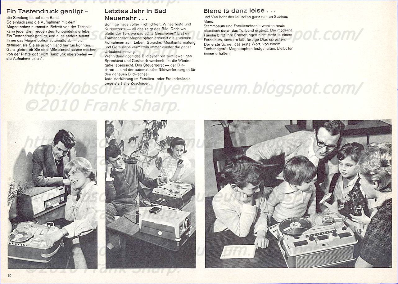
AEG-Telefunken delivered the two-millionth tape recorder, a Magnetophon 204 TS, on August
5, 1969. The ten-millionth black-and-white television picture tube was produced in Ulm on
January 27, 1970. The numbers are astounding. As is Telefunken.AEG-Telefunken delivered the
two-millionth tape recorder, a Magnetophon 204 TS, on August 5, 1969. The ten-millionth
black-and-white television picture tube was produced in Ulm on January 27, 1970. The
numbers are astounding. As is Telefunken.


ECONOMIC SLOWDOWN


There was a worldwide economic slowdown in the wake of the oil crisis in 1974. The
competition in consumer electronics sector also became more difficult due to Japanese
suppliers. The only profitable divisions of the company at this time were telecommunications
and traffic technology. But Telefunken, as usual, was known for their resilience.


1979- 1983
THE NAME GAME CONTINUES

The name of the overall company was changed to AEG-Telefunken Aktiengesellschaft on June
21, 1979. The "Aktiengesellschaft" [stock corporation] suffix was necessary due to a new law in
the European Community. In 1979, AEG-Telefunken supplied the complete telecommunications
and high-voltage equipment for the International Congress Center (ICC) Berlin, valued at DM 50
million. In January 1983 the company received an order for simulation systems for electronic
battle simulation for training Tornado crews of the German Luftwaffe and Navy. The total value
was at DM 37 million. The net worth: priceless.
TOUGH TIMES FOR TELEFUNKEN

Court composition proceedings were opened against the assets of AEG-Telefunken AG by the
District Court in Frankfurt / Main on October 31, 1982.
The District Court Frankfurt / Main confirmed the composition of AEG-Telefunken AG in
accordance with the petition filed and closed the proceedings on September 19, 1984.
Even during this difficult financial situation, AEG-Telefunken continued its business and founded
AEG-Telefunken Nachrichtentechnik GmbH (ATN), in Backnang, Germany, together with
Bosch, Mannesmann and Allianz Versicherungs-AG in 1981, as well as Telefunken electronic
GmbH (TEG) in the field of electronic components (semiconductors) together with United
Technologies Corporation (UTC), USA in 1982.
On July 1, 1992, AEG-Telefunken and Deutsche Aerospace (Dasa) founded Telefunken
Microelektronic GmbH (TEMIC), into which Telefunken Elektronic GmbH was integrated among
others. But Telefunken was determined to prevail.
A FINAL, BUT NOT LAST, TURN
Effective March 31, 1983, the French group Thomson-Brandt S.A. took over 75 percent of the
AEG-Telefunken shares in Telefunken Fernseh und Rundfunk GmbH, Hanover, Germany,
including its German and foreign subsidiaries. The remaining 25 percent were supposed to
follow on January 31, 1984. Daimler-Benz AG entered the company in autumn of 1985 and
decided in Autumn 1995 to dissolve the legal entity and transferred the remaining assets to
EHG Electroholding GmbH. Thus, the history of the company was over. But not that of its
brands.
A historical overview is offered by the company archive of AEG-Telefunken in the "Deutsches
Technikmusem Berlin", Trebbiner Str. 9, 10963 Berlin.
1984 – 2004
INNOVATION YESTERDAY. TODAY. AND TOMORROW
Currently, the Telefunken brand and name rights lie with Telefunken Licenses GmbH,
Frankfurt/Main, Germany. This company is one hundred percent subsidiary of EHG
Elektroholding GmbH, Frankfurt/Main.
EHG, on the other hand, is the legal successor of AEG Aktiengesellschaft. The licensor is
Licentia Patent-Verwaltungs GmbH, Frankfurt/Main, Germany. A differentiation is made
between brand licensing agreements, name use agreements and combined agreements. And
third-party use always requires the written approval of the licensor.
In 2003, Telefunken can look back at one-hundred years of brand history. In the past,
Telefunken was associated with significant technical developments and enjoyed the reputation
of a successful German company.
The Telefunken brand is registered in the official trademark registries of 118 countries. It
continues to be used under a variety of licensing agreements.
These are the topics that can be found in the commemorative volume "Telefunken After 100
Years - The Legacy of a Global German Brand."
Whether discovered on this website or in book, these topics should not only focus attention on
the past, but also simultaneously highlight the beginning of a strong Telefunken brand. Simply
put, it’s not just about where we’ve been. But also where we’re going.
2004 – 2009
TELEFUNKEN TODAY
Since December 2007, the trademark-right TELEFUNKEN rests with TELEFUNKEN Holding
AG, Frankfurt. Currently, TELEFUNKEN is the owner of more than 20,000 patents and active in over 130 countries around the globe.
Today, TELEFUNKEN stands for innovation and progress in the ever-changing world of
information and communications technology and is strictly focused on consumer quality – from
design concept to execution. And because of its strong heritage and long-standing tradition,
Telefunken has a high brand-awareness and a clear positioning in the field of premium
products.
Thomson-CSF was a major electronics and defence contractor. In December 2000 it was renamed Thales Group.
History
In 1879 Elihu Thomson and Edwin Houston formed the Thomson-Houston Electric Company in the United States.On April 15, 1892 Thomson-Houston and the Edison General Electric Company merged to form General Electric (GE). Also in 1892 the company formed a French subsidiary, Thomson Houston International.
In 1893 Compagnie Française Thomson-Houston (CFTH) was set up as a partner to GE. It is from this company that the modern Thomson companies would evolve.
In 1966 CFTH merged with Hotchkiss-Brandt to form Thomson-Houston-Hotchkiss-Brandt (soon renamed Thomson-Brandt). In 1968 the electronics business of Thomson-Brandt merged with Compagnie Générale de Télégraphie Sans Fil (CSF) to form Thomson-CSF. Thomson Brandt maintained a significant shareholding in this company (approximately 40%).
In 1982 both Thomson-Brandt and Thomson-CSF were nationalized by François Mitterrand. Thomson-Brandt was renamed Thomson SA (Société Anonyme) and merged with Thomson-CSF.
From 1983 to 1987 a major reorganisation of Thomson-CSF was undertaken, with divestitures to refocus the group on its core activities (electronics and defence). Thomson-CSF Téléphone and the medical division were sold to Alcatel and GE respectively. The semiconductor businesses of Thomson CSF was merged with Finmeccanica. Thomson acquired General Electric’s RCA and GE consumer electronics business in 1987.
In 1988 Thomson Consumer Electronics was formed, renamed Thomson Multimedia in 1995. The French government split the consumer electronics and defence businesses prior to privatisation in 1999, those companies being Thomson Multimedia (today Technicolor SA) and Thomson-CSF (today Thales Group).
Thomson-CSF was a major electronics and defence contractor. In December 2000 it was renamed Thales Group.
...........1996............there are no stranger foreigners than the first ones you come across, the French. This is borne out by the 1996 Thomson situation. Thomson, was a vast company by any reckoning, is a strange beast. It's state controlled, which means that the government owns most but not quite all of it. and consists of two distinct arms, the defence group Thomson-CFS which is quite profitable, and the consumer electronics group Thomson Multimedia which loses a packet. The government wanted rid of it, but won't sell the bits separately. It doesn't want to be left with the problem of what to do with Thomson Multimedia. You might think that no one would be interested in helping the French government. But in fact there are two contenders to take over Thomson, the telecommunications and power group Alcatel Alsthom and the defence and media group Lagardere. They have been engaging in quite a battle over the ownership, and as we go to press the French government is due to decide whose bid to accept. Whoever wins will end up with the profitable defence company and the problem of Thomson Multimedia (TMM).
Lagardere has stated that it would sell TMM to Daewoo of Korea. Alcatel Alsthom has not been quite so specific, but has announced that it would take immediate action to reduce TMM's losses and seek an "Asian partner" that "specialises in consumer electronics". The partner would be expected to take over management of TMM, but Alcatel would like to remain a "minority partner" - it sees prospects in the move to digital TV technology that will occur during the next decade. All this gives one a strange feeling of déjà vu. At the time when Thomson took over Ferguson, in June 1987, it was noticed that Thomson is "now on the government's privatisation list". It's taken almost a decade to happen.
It's also said that "Thomson may be big, but has not been all that successful in the past in the consumer electronics field". Right on! What has happened to Ferguson in the UK illustrates the dismal Thomson effect. From being the local brand leader, with over ten per cent of the market, Ferguson has ended up being an also ran. It's only fair however to mention that Ferguson was making substantial losses when Thorn EMI was glad to get £90m for it from Thomson. Thomson has been able to survive in the consumer electronics field because it is part of a larger organisation, with those defence profits. It has nevertheless over the years attempted to play a a major role in the international consumer electronics field, keeping up with Philips and the Japanese corporations. From its French origins, it first expanded by picking up various German companies such as NordMende an SABA. It added Telefunken, a venerable name if ever there was one in this industry, in the early eighties, then took what was to be a big move into the UK market when it bought Ferguson.
It used six brand names in Europe. The largest step however occurred when TMM became a major force in the North American market by taking over General Electric's consumer electronics interests. This also gave it the RCA operation. The idea behind all this seems to have been to achieve success simply by getting bigger. There was always government finance to back the policy, which in the event has not been a success. The TMM debacle is a sad one, since Thomson's research and engineering has had many successes.
It has not stinted on R and D work, with laboratories in Los Angeles, Indianapolis, Strasbourg, Hanover, Villingen, Tokyo and Singapore. Much work has been done on HD -TV, digital signal processing and other developments that have kept it in the forefront of the technology. Now, it seems, TMM is likely to be swallowed up by one of the Oriental corporate giants.
If there are any lessons to be drawn, they would seem to be that expansion by itself is no guarantee of success, that to spread ones activities and their control across the globe makes management extremely difficult, and that costs are very hard to control in such a context. Alcatel Alsthom's plans to reduce TMM's losses bear this out. It would close down TMM's US factories, transferring production to the company's modern facilities in Mexico, where wages are much lower.
It would rationalise the large collection of brands, possibly adopting RCA as the main one worldwide. And there is a suggestion that the company should be run from the USA, since this is its largest market. But all this would be just initial steps towards ceding majority control. Venerable brand names such as Telefunken, GE and RCA would pass to oriental ownership. This will happen whoever wins, Alcatel Alsthom or Lagardere, which would leave just Philips to carry on Europe's traditions in the consumer electronics field............. but we all know how it ended.................
Thomson-CSF independence
Following the privatisation of the Thomson Group Thomson-CSF explored the possibility of merging with Marconi Electronic Systems, however British Aerospace was successful in that aim, forming BAE Systems.In 2000 Thomson-CSF went through a series of transactions, including with Marconi plc. The major acquisition at this time was the £1.3 billion purchase of the British defence electronics firm, Racal. This made Thomson-CSF the second largest participant in the UK defence industry after BAE. Racal was renamed Thomson-CSF Racal plc.
On December 6, 2000 the group was renamed Thales.
------------------------------------------------------
Some References:
- M. Friedewald: Telefunken und der deutsche Schiffsfunk 1903–1914. In: Zeitschrift für Unternehmensgeschichte 46. Nr. 1, 2001, S. 27–57
- M. Fuchs: Georg von Arco (1869–1940) – Ingenieur, Pazifist, Technischer Direktor von Telefunken. Eine Erfinderbiographie. Verlag für Geschichte der Naturwissenschaften und der Technik, Berlin & München: Diepholz 2003
- L. U. Scholl: Marconi versus Telefunken: Drahtlose Telegraphie und ihre Bedeutung für die Schiffahrt. In: G. Bayerl, W. Weber (ed.): Sozialgeschichte der Technik. Ulrich Troitzsche zum 60. Geburtstag. Waxmann, Münster 1997 (Cottbuser Studien zur Geschichte von Technik, Arbeit und Umwelt, 7)
- Telefunken Sendertechnik GmbH: 90 Jahre Telefunken. Berlin 1993
- Erdmann Thiele (ed.): Telefunken nach 100 Jahren – Das Erbe einer deutschen Weltmarke. Nicolaische Verlagsbuchhandlung, Berlin 2003, ISBN 3-87584-961-2
Einzelnachweise:
Schreibweise mit c siehe: - AEG-Teilschuldverschreibung von 1962Marke „Telefunken“ in der Registerauskunft des Deutschen Patent- und Markenamtes (DPMA)
E. Thiele (Hrsg.): Telefunken nach 100 Jahren: Das Erbe einer deutschen Weltmarke. Nicolai, Berlin 2003, S. 19
Kurt Kracheel: Flugführungssysteme (Die Deutsche Luftfahrt, Band 20). Bernard&Graefe Verlag, Bonn 1993, ISBN 3-7637-6105-5, S. 119.
Operette 50W UKW. In: radiomuseum.org. Abgerufen am 28. Januar 2016.
Autosuper IA 50. In: radiomuseum.org. Abgerufen am 28. Januar 2016.
Farbfernseh-Tischempfänger PALcolor 708T. In: radiomuseum.org. Abgerufen am 28. Januar 2016.
Mini Partner 101. In: radiomuseum.org. Abgerufen am 28. Januar 2016.
Olympia-Partner. In: radiomuseum.org. Abgerufen am 28. Januar 2016.
Magnetophon 3000 hifi. In: radiomuseum.org. Abgerufen am 28. Januar 2016.
Fernseh-Tischempfänger FE8T. In: radiomuseum.org. Abgerufen am 28. Januar 2016.
Israelischer Konzern Elbit Systems eröffnet Büro in Berlin. In: bundeswehr-journal. 13. April 2018, abgerufen am 18. Januar 2019.
Telefunken Semiconductors Heilbronn: Die Lichter sind für immer aus, swr.de, 27. Februar 2015
LDL Berlin: Geschäftshaus Mehringdamm 32 & 34
LDL Berlin: AEG-Glühlampenfabrik
LDL Berlin: AEG-Telefunken-Gerätewerk
Telefunkenwerk Celle. vergessene-orte.blogspot.com
Ludwig Leisentritt: Die historische Entwicklung von Zeil am Main, hbrech.tripod.com
R.I.P. TELEFUNKEN 


