
Audio visual SCART Connector is a topic that affects anyone with a OBSOLETE CRT television system, hi-fi or any audio, video or audio visual system. Knowing a little about these systems enables them to be installed and maintained more easily as well as allowing the best to be made from each system.

The SCART (Peritel) connection system is an older / obsolete connection standard used mainly within Europe to connect different audio and video systems together. It appears on televisions, video recorders, DVD players and many other items enabling the video to be streamed from one unit to another.
- SCART connections generally offer the best quality video at standard-definition, due to the use of pure RGB signalling (although composite and S-Video may alternatively be offered over a SCART connector). SCART provides video and audio in one connection.
SCART Interface
audio video SCART (from Syndicat des Constructeurs dAppareils Radiorécepteurs et Téléviseurs) is a French-originated standard and associated 21-pin connector for connecting audio-visual equipment together. It is also known as Péritel (especially in France) and Euroconnector. SCART makes it easy to connect AV equipment (including TVs, VCRs, DVD players and games consoles). In essence, it gathers together various common analog signal-types into a single connector. Nowdays is obsolete and superseded by HDMI. The signals carried by SCART include both composite and RGB video, and stereo audio input/output, as well as support functions. May be converted to VGA, S-video.The voltage levels are rather high, around 1V, so the signals have good noise immunity.
Although the connector is rather unwieldy and the cables are thick and difficult to manage, the SCART standard caught on and was used for many early televisions, video cassette recorders, VCRs, early gaming systems and the like. It was even used for some professional equipment as well. (The puny and fragile pins need only the slightest lateral movement and they either snap or break the moulded housing of the socket.)
- The advantage of SCART is that it is able to handle composite, audio, and RGB data. Additionally using wide flat pins the connections are less prone to damage than the round pins used in some other connectors. With SCART connectors and cables being used in many areas, a robust connector is a great advantage.The Scart plug and socket are extremely common on DVD players, set top boxes etc and the Scart cable carries audio & video so it is a one plug solution for audio / video unit connections.
Standards
SCART: CENELEC EN 50 049-1:1989
SCART: IEC 60933-1:1988 (old name: IEC 933-1:1988)
D²B: CENELEC EN 61030
D²B: IEC 61030:1991 (old name: IEC 1030:1991)
In view of the fact that SCART was designed to carry analog standard-definition content in the days before digital television became commonplace its use is now declining. Digital television and other more compact systems like HDMI have increased in use and SCART use has significantly dropped as it cannot carry digital signals. Nevertheless SCART connectors are still incorporated into most modern televisions to enable connectivity with older AV equipment.
- SCART was first released on equipment in 1977 and it was standardised as CENELEC document number EN 50049-1, but is also sometimes referred to as IEC 933-1.

EN 60065, Safety requirements for mains operated electronic and related apparatus for household and similar general use. (IEC 60065, modified) IEC 60268-15, Sound system equipment Ð Part 15: Preferred matching values for the interconnection of sound system components. (harmonized as HD 483.15 S4:1992) IEC 60608, Interconnections between video-tape recorders and television receivers for 50 Hz-625 lines. NOTE IEC 60608 is restricted to a specific system, whereas this standard relates to an interconnection system intended to cover a substantially wider scope. Thus in particular, the interconnection as defined in IEC 60608 does not provide for simultaneous conveyance, on separate pins, of receiver input and output (audio and video) signals in order to be processed by a peripheral device. IEC 60807-9, Rectangular connectors for frequencies below 3 MHz Part 9: Detail specification for a range of peritelevision connectors. IEC 60933-1, 21 pin-connector for video systems (Application No. 1 and Amendment 1). Recommendation ITU-R draft (11 A/XE ``Enhanced wide-screen PAL TV transmission system'').
A SCART connector is a physical and electrical interconnection between two pieces of audio-visual equipment, such as a television set and a video cassette recorder (VCR). Each device has a female 21-pin connector interface. A cable with a male plug at each end is used to connect the devices. (The 21st pin is actually not a pin but a ground shield contact.) Stereo audio, composite video, and control signals are provided in both directions. RGB video signals are input only. The interface is an industry standard originated by the French company, Peritel. Today, most new television sets and VCRs in the European market and other countries that use the PAL video standard come equipped with a SCART connector. SCART stands for Syndicat francais des Constructeurs d'Appareils Radio et Television. The connector is also known as a Euro-connector.
This
standard defines the interconnection characteristics of peritelevision
devices, both between themselves and with television receivers
(monochrome or colour). The interconnections covered by this standard
are at baseband (video and audio) or digital signals. For the purpose of
defining conformance, this standard specifies the types and related
groups of signals, composite video, audio, primary colour and control
that shall be present on the connectors. The levels and impedances
together with the tolerances on these values are also specified. The
manner in which the signals on the connector are processed within the
products incorporating the connectors and the presentation of the
results of such processing to the user is outside the scope of this
standard. These details depend upon the system involved, e.g. PAL or
SECAM and the specification of the product. This standard lays down
collectively the electrical matching characteristics (type of signals,
voltage and impedance values), dimensional, mechanical and electrical
characteristics of the connectors, type and wiring of interconnection
cordsets. Attention is drawn to the fact that the interconnection
covered by this standard shall in any circumstances meet the safety
requirements specified in EN 60065:1993 and the electromagnetic
compatibility requirements specified in the appropriate publications.
This
standard applies to the connector socket mounted on various devices
that are components of domestic audio-visual systems, and includes the
designation of contacts, the type of interchanged signals and the
matching values of voltage and impedance. This standard does not apply
to equipment so small that its size is not compatible with the
dimensions of the socket. It applies also to the plug fitted to the end
of interconnection cordsets. It covers the interconnection cordsets
themselves (type of conductors, wiring). Permanent connection of several
pieces of equipment which may be used simultaneously or otherwise is
ensured: Ð either by fitting each piece of equipment with a suitable
number of connectors; Ð or by a single connector on each piece of
equipment linked to a central interconnection and switching device. The
user shall be informed about the possible applications that are provided
by a device.
General description
The
``peritelevision'' connector consists of two elements. A female part,
the ``socket'', permanently mounted on pieces of equipment and
permanently wired to the relevant circuits or elements. All contacts
designated as return have to be effectively connected to the reference
potential. A male part, the ``plug'', located at the end of the cordset.
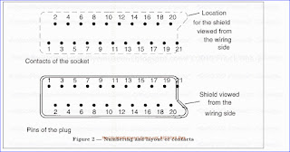
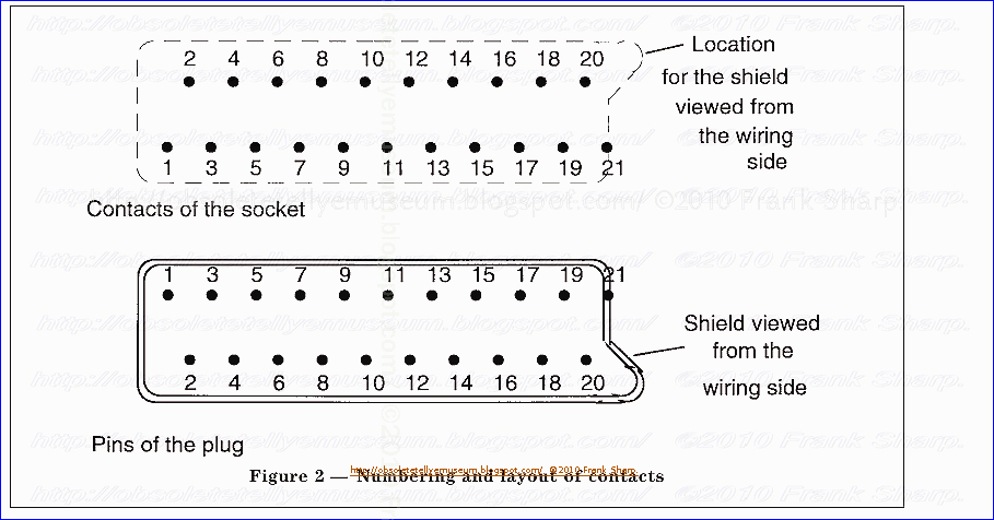
Connections between socket and plug consist of 2 rows of 10 contacts in
a staggered arrangement (plus a special ``shield'' contact).
Depending on the SCART connector's use (TV SCART, AUX SCART, or VCR SCART) the connector is an input, an output, or both. The addition of S-VHS has complicated this interface by requiring the RED and Cvbs signals (pins 15 & 20) to be shared with the Chroma (C) and Luma (Y) pins.
Mechanical characteristics
the
centre-to-centre distance between contacts in a row is 3,81 mm. the
distance between the centre-lines of the rows is 5,08 mm.
Socket
The
socket consists of two rows of female contacts in a staggered
arrangement (one row of 10 contacts and one row of 11 contacts). The
contact 21 provides connection with the plug shield.
SCART pinouts
Different pin-configurations exist. Which confirations are available depends on the video device used. Sometimes one can choose the configuration (like composite or S-video) by changing a software setting.
Two status signals define (partly) which video signals are active. A video device can use these status signals to automatically switch between internal or external audio/video signals.
General remarks:
All input and output signals may be present simultaneously. All input and output signals are defined and measured taking into account the appropriate CCIR and IEC Publications.
In most cases, specialized ICs are used for the SCART Interface because of the complicated switching required, but that approach isn't cost effective for smaller unidirectional implementations. (The simplest form is the single SCART switch found on TV inputs and encoder outputs.)
| Pin | Name | Description | Signal Level | Impedance |
|---|---|---|---|---|
| 1 | AOR | Audio Out Right | 0.5 V rms | <1k ohm |
| 2 | AIR | Audio In Right | 0.5 V rms | >10k ohm |
| 3 | AOL | Audio Out Left + Mono | 0.5 V rms | <1k ohm |
| 4 | AGND | Audio Ground | ||
| 5 | B GND | RGB Blue Ground | ||
| 6 | AIL | Audio In Left + Mono | 0.5 V rms | >10k ohm |
| 7 | B | RGB Blue In | 0.7 V | 75 ohm |
| 8 | SWTCH | Audio/RGB switch / 16:9, slow switch (10-12v), to force tv to switch on a mode (depends of the tv(old), sometimes set tv to AUX) | ||
| 9 | G GND | RGB Green Ground | ||
| 10 | CLKOUT | Data 2: Clockpulse Out, used in the 80s by old videotapes | ||
| 11 | G | RGB Green In | 0.7 V | 75 ohm |
| 12 | DATA | Data 1: Data Out (Unavailable ??) | ||
| 13 | R GND | RGB Red Ground | ||
| 14 | DATAGND | Data Ground, remote control, wired and used by old videotape recorders | ||
| 15 | R | RGB Red In / Chrominance | 0.7 V (Chrom.: 0.3 V burst) | 75 ohm |
| 16 | BLNK | Blanking Signal, fast switch (1-3v), to force tv to switch on a mode (depends of the tv(recent), sometimes set tv to AUX) | 1-3 V=RGB, 0-0.4 V=Composite | 75 ohm |
| 17 | VGND | Composite Video Ground or S-video luminance Ground | ||
| 18 | BLNKGND | Blanking Signal Ground - ground for slow or fast switch (ground for pin 8 or 16) | ||
| 19 | VOUT | Composite Video Out | 1 V | 75 ohm |
| 20 | VIN | Composite Video In / Luminance / RGB Sync | 1 V | 75 ohm |
| 21 | SHIELD | Ground/Shield (Chassis) |
Two pins provide switching signals.
Pin 8, the function switching pin, carries a low frequency (less than
50Hz) signal from the source that indicates the type of video present.
0V-2V means no signal, or internal bypass
4.5V-7V (nominal 6V) means a widescreen (16:9) signal
9.5V-12V (nominal 12V) means a normal (4:3) signal
Pin 16, the fast switching pin, carries a signal from the source that indicates that the signal is either RGB or composite.
0V-0.4V means composite.
1V-3V (nominal 1V) means RGB only.
The original specification defined pin 16 as fast blanking, a high frequency (up to 3MHz) signal that blanked the composite video. The RGB inputs were always active and the fast blanking signal punches holes in the composite video. The SCART connector uses this to overlay subtitles from an external Teletext decoder. 0V-0.4V means composite with a transparent RGB overlay. 1V-3V (nominal 1V) RGB only.
There is no switching signal to indicate S-Video. Some TVs can autodetect the presence of the S-Video signal but more commonly the S-Video input needs to be manually selected.
D²B
D²B=Domestic Digital Bus
Pin 10, 12 and 14 was used for a databus by Philips, now called IEC 61030, USED IN DIGI16 CHASSIS, Not used anymore.
D²B is a multi-master bus. Collision detect with CDMA/CD.
Blanking
Pin 16 is used to select between RGB & composite video. Input impedance is 75 Ω, so use 180 Ω resistor from +5V to activate RGB. This should give +1.5VDC at pin 16. Tip: Pin 9 at VGA connectors is +5V.
Many older TV sets have 2 SCART sockets. One is usually uses previous pinout table and the other uses following pinout table. The first can switch from a composite input to RGB input. The second can switch from a composite input to an S-Video input, pin 20 being either composite in or luminance in. Usually the second socket outputs a selectable composite signal on pin 19
| Pin | Signal | Level | Impedance |
| 1 | Audio Out Right | 0.5 V rms | <1k ohm |
| 2 | Audio In Right | 0.5 V rms | >10k ohm |
| 3 | Audio Out Left + Mono | 0.5 V rms | <1k ohm |
| 4 | Ground Audio | ||
| 5 | RGB Ground Blue | ||
| 6 | Audio In Left + Mono | 0.5 V rms | >10k ohm |
| 7 | - | - | - |
| 8 | Fuction Select | High (9.5-12V) AVmode Low (0-2V) TVmode |
>10kohm |
| 9 | RGB Ground Green | ||
| 10 | Comms Data 2 | ||
| 11 | - | - | - |
| 12 | Comms Data 1 | ||
| 13 | Ground (chrominance) | ||
| 14 | Ground Data | ||
| 15 | Chrominance input | 0.3V | 75 ohm |
| 16 | - | - | - |
| 17 | Ground (luminance) | ||
| 18 | - | - | - |
| 19 | Video output (composite) | 1V including sync | 75 ohm |
| 20 | Luminance input | 1V including sync | 75 ohm |
| 21 | Ground/Shield (Chassis) |
SCART Signal Levels
| Signal | AC level | DC level | Impedance |
|---|---|---|---|
| Red, green, blue | Peak to blanking: 0...0.7 V ?3 dB | 0...2 V | 75 Ohm |
| Sync | Peak to peak: 0...0.3 V -3 dB...+10 dB | 0...2 V | 75 Ohm |
| Composite video | White to sync: 0...1.0 V ?3 dB | 0...2 V | 75 Ohm |
| Chrominance | 0...0.3 V -3 dB...+10 dB | 0...2 V | 75 Ohm |
| Luminance | 0...1.0 V 3 dB | 0...2 V | 75 Ohm |
| MAC | Black to white: 0...1.0 V 3 dB | 0...2 V | 75 Ohm |
| Audio in | 0.2...2.0 V (nominal: 0.5 V) | >=10 kOhm | |
| Audio out | Nominal: 0.5 V (maximum: 2.0 V) | <=1 kOhm | |
| Video status | Low data rate communication: 0.0...2.0 V (e.g. remote control; Easylink) |
Internal: 0.0...2.0 V External (16:9): 4.5...7.0 V External (4:3): 9.5...12.0 V |
In: ZR>=10 kOhm ZC<=2 nF Out: ZR<=1 kOhm |
| RGB status | Internal: 0.0...0.4 V External: 1.0...3.0 V |
75 Ohm |
A formal interface description is given in the CENELEC EN 50 049-1:1989 standard or in the IEC 933-1 standard.
- Although it is possible to build your own connecting cable, knowledgable people recommend buying a commercial cable because of the detailed pin-crossovers and close pin connections. Differerent cables serve different purposes. A cable for connecting a VCR or a TV set to a high-fidelity audio system needs to use only three of the 21 pins.
It is more difficult to use the SCART connector to interconnect a VCR to a computer monitor because of the difficulty of synchronizing the composite video signal (which is companded into red, green, and blue) from the VCR with the RGB signals needed by the monitor.
A user reports that the torsional load of the cable can in time lead to difficulty getting all the connections to align properly

SCART to S-Video cable:
| Output connector | Input connector | ||
|---|---|---|---|
| 1 | Audio right out | 2 | Audio right in |
| 3 | Audio left (or mono) out | 6 | Audio left (or mono) in |
| 4 | Audio return | 4 | Audio return |
| 15 | Chrominance out | 15 | Chrominance in |
| 13 | Chrominance return | 13 | Chrominance return |
| 8 | Video status out | 8 | Video status in |
| 19 | Luminance out | 20 | Luminance in |
| 17 | Luminance return |
17 |
Luminance return |
| 21 | Shield | 21 | Shield |
SCART to Composite Video cable
| Output connector | Input connector | ||
|---|---|---|---|
| 1 | Audio right out | 2 | Audio right in |
| 3 | Audio left (or mono) out | 6 | Audio left (or mono) in |
| 4 | Audio return | 4 | Audio return |
| 8 | Video status out | 8 | Video status in |
| 19 | Composite video out | 20 | Composite video in |
|
17 |
Composite video return | 18 | Composite video return |
| 21 | Shield | 21 | Shield |
Composite Decoder Connection
| Receiver connector | Decoder connector | ||
|---|---|---|---|
| 1 | Audio right out | 2 | Audio right in |
| 2 | Audio right in | 1 | Audio right out |
| 3 | Audio left out | 6 | Audio left in |
| 6 | Audio left in | 3 | Audio left out |
| 4 | Audio return | 4 | Audio return |
| 8 | Video status in | 8 | Video status out |
| 19 | Baseband out (scrambled) | 20 | Baseband in |
| 17 | Baseband out return | 18 | Baseband in return |
| 20 | Composite video in (unscrambled) | 19 | Composite video out |
|
17 |
Composite video in return | 17 | Composite video out return |
| 21 | Shield | 21 | Shield |
21 PIN SCART MALE to the Video Recorder.
| |
TV | VCR |
|
|---|---|---|---|
| Audio Right Out | 1 | 2 | Audio Right In |
| Audio Right In | 2 | 1 | Audio Right Out |
| Audio Left Out | 3 | 6 | Audio Left In |
| Audio Left In | 6 | 3 | Audio Left Out |
| Audio Ground | 4 | 4 | Audio Ground |
| |
|
|
|
| Red | 15 | 15 | Red |
| Red Ground | 13 | 13 | Red Ground |
| Green | 11 | 11 | Green |
| Green Ground | 9 | 9 | Green Ground |
| Blue | 7 | 7 | Blue |
| Blue Ground | 5 | 5 | Blue Ground |
| |
|
|
|
| Status / 16:9 | 8 | 8 | Status / 16:9 |
| Reserved | 10 | 10 | Reserved |
| Reserved | 12 | 12 | Reserved |
| Fast Blanking Ground | 14 | 14 | Fast Blanking Ground |
| Fast Blanking | 16 | 16 | Fast Blanking |
| Video Out Ground | 17 | 18 | Video In Ground |
| Video In Ground | 18 | 17 | Video Out Ground |
| Video Out | 19 | 20 | Video In |
| Video In | 20 | 19 | Video Out |
| Ground | 21 | 21 | Ground |
Not all equipments are capable of outputting RGB signals. For example typical VCRs usually only output composite video. The equipmets from where you might expect to get RGB are some DVD players, some computer to TV interfaces and similar devices.
SCART pins used in RGB mode:
 5   RGB Blue Ground
 7   RGB Blue Signal  (0.7Vpp 75 ohm)
 9   RGB Green Ground
11   RGB Green Signal (0.7Vpp 75 ohm)
13   RGB Red Ground
15   RGB Red Signal (1Vpp 75 ohm)
17   Composite Video Ground
19   Composite Video Out (1Vpp 75 ohm)
20   Composite Video In  (1Vpp 75 ohm)
On pins 19 and 20 please notice that a typical standard SCART cable
the pins 19 and 20 are crossed with each other. The equipment which
outputs RGB or composite video signal, the composite video is
available on pin 19 at the female connector on the back of the
signal sending equipment. The same signal is then available on
the pin 20 at the other end of the SCART cable.
The composite video signal has amolitude of 1Vpp, which consists of 0.3Vpp composite sync signal plus 0.7Vpp picture signal.
SCART RGB to 4 BNC inputs
You might in some cases want to feed the RGB from SCART to some video equipment with other type of interface. One example of such equipment would be a video projector with RGB inputs with BNC connectors. The following wiring can be used for connecting an RGB signal from SCART connector to a video equipment with RGB and composite sync input.

The wiring needs an sync amplifier circuit, because the 0.3Vpp composite sync signal which is included in normal composite video signal is not generally stron enough for the sync inputs used in video projectors. Depending the projector, they usally need a sych with amplitude from atleast 0.5 to 2V to operate correctly. composte video to sync. This means that if you feed that composite vidoe signal directly then generally the video projector does not sync at all or does not sync reliably.

Sync separation and amplifications electronics is almost always always needed to get the projector to work correctly. The following circuit can be used to do the sync separation and amplification.

SCART Cordsets

- As all pieces of the equipment that comprise the domestic audio-visual system are equipped with ``female'' sockets, the junctions are made by cords fitted at each end with a ``male'' plug.
- To provide for certain particular circumstances, an extension cord fitted with a ``male'' plug at one end and a ``female'' plug at the other end may be used. The possibility of linking together two ``male-male'' cords may be provided for by means of a cordset fitted with ``female'' plugs at each end.
Since certain of the connectors contacts are specifically for input or output functions (audio and video) and clearly intended to connect one input to one output, but not two inputs or two outputs together, the cordset shall incorporate the means for making the necessary cross-connections.
- In a situation in which several cordsets are linked together in succession, it is essential for the number of crossings to be odd. The following rule shall be applied:male-male cordset : crossing male-female extension cord : no crossing female-female cordset : crossing
Scart to RCA and S-Video:

SCART S-Video Connection

| Output connector | Input connector |
|---|---|
| 1 | Audio right out |
| 3 | Audio left (or mono) out |
| 4 | Audio return |
| 15 | Chrominance out |
| 13 | Chrominance return |
| 8 | Video status out |
| 19 | Luminance out |
| 17 | Luminance return |
| 21 | Shield |
SCART Composite Video Connection
| Output connector | Input connector |
|---|---|
| 1 | Audio right out |
| 3 | Audio left (or mono) out |
| 4 | Audio return |
| 8 | Video status out |
| 19 | Composite video out |
| 17 | Composite video return |
| 21 | Shield |
- Nature of the conductors
- The conductors conveying video signals or equivalent, namely those connected to the pairs of contacts (19, 17), (20, 18), (15, 13), (11, 9), (7, 5), (16, 14), are of the coaxial type 75 V (characteristic impedance).
- The conductors conveying audio signals are of the screened cable type for audio frequencies (contacts 3, 1, 6, 2, 4).
- The conductors conveying digital data (contact 10, 12, 21) are of the screened cable type for audio frequencies. The connection corresponding to contact 8 is by means of a single insulated wire.

Cordset types
Five
types of cordset may be considered suitable, according to the intended
use:

Cordset type U (Universal). This cordset incorporates all the interconnections covered by this standard. It is identified by a black marking. Cordset type V (Video only).
This cordset incorporates connections 8, 19, 17, 20, 18, 15, 13, 11, 9, 7, 5, 16, 14, 10, 12, 21. It is identified by a white marking.
Cordset type C (Audio and composite video but not the R.G.B. primary colour signals) Ð It includes the interconnections of contacts 3, 1, 6, 2, 4, 8, 10, 21, 12, 17, 19, 18, 20. It is identified by a grey marking.
Cordset type A (Audio only). It incorporates all the interconnections other than those concerned with video. It includes the interconnections of contacts 3, 1, 6, 2, 4, 8, 10, 12, 21. It is identified by a yellow marking.
- Cordset type B (Data bus only). This cordset only provides interconnection of contacts 10, 12, 21 and no others. It is identified by a green marking. NOTE Marking with the appropriate colour on or close to the socket may indicate the suitable cordset(s).
Essential/optional signal types for various applications
General rules:
- The signals on some contacts can be optional or of different types. The instructions for the use of this connector for each device shall describe the use of the contacts that are effectively wired.
- A device may be provided with several peritelevision connectors. In this case at least one shall conform to this standard. The use of the remaining connector(s) shall be described in the instructions for that device.
- All return contacts shall be connected in the device. In case of monophonic sound both output contacts 1 and 3 shall deliver the same signal with the required matching values .
- To enable the television receiver to proceed signals applied at pins of the peritelevision connector, the first condition is to apply at pin 8, a voltage corresponding at logical level ``1A'' or ``1B'', also to proceed R, G, B signals.
- In case of RGB signals the synchronising signal must be derived from the signal on pin 20.
- The C99 signal will be applied on pin 7 in the ``down stream'' direction by a device which conforms the AV-link. If a connection to such a device is required then this signal must be available in the appropriate direction. However, there is equipment in the market, mainly VCR's which apply the C99 signal on pin 15 in both directions depending on the mode of operation. To ensure backward compatibility suitable switching of the C99 signal may be required.
- It is recommended that restitution of audio or video signals is the same, irrespective of the path, when the signal comes from an internal or external source.

- There is also a Japanese version of the SCART connector. This is often referred to as Japanese RGB-21 connector, and it is standardised under the Japanese organisation EIAJ TTC-003, and sometimes called JP-21. It uses similar signals and the same connector, but it has a different pinout. If a picture with red video with no audio is experienced, this is indicative of mismatching JP-21 SCART with European SCART connectors.
 CRITICISM ABOUT AV SCART CONNECTOR:

- The design details resulting from the standard can lead to contact problems and damage when using the plug, especially when it is frequently reconnected:
- The individual contacts are flat and thin, and fixation within the connector is via small tongues. As a result, contacts can easily be bent or slip backwards in the carrier.
- The grounding plate sometimes gets stuck in the socket when it is pulled off.
- The standard does not require the sockets and plugs to be screwed to the board or housing. Therefore, the easily broken solder joints must absorb forces that act on the plug and socket during movement. Due to the generally angled cable routing, a slight pull or pressure on the rather rigid cable is enough to lever the plug out of the socket on one side; this results in picture or sound failure that cannot be clearly assigned to the scart connection.
Japanese SCART connector JP21 pinout
The pin connections or pinout for the Japanese SCART connector also known as JP21 is different to that of the original French or European SCART.
| Pinout for Japanese SCART JP21 |
|
|---|---|
| SCART Connector Pin Number | SCART Pin Function |
| 1 | Audio input (left) |
| 2 | Audio output (left) |
| 3 | Audio ground |
| 4 | Audio ground |
| 5 | Audio input (right) |
| 6 | Audio output (right) |
| 7 | Video ground |
| 8 | Video ground |
| 9 | Composite video input |
| 10 | Composite video output |
| 11 | AV control input |
| 12 | Ym input |
| 13 | Red signal ground |
| 14 | Ground |
| 15 | Red signal I/O |
| 16 | Ys input |
| 17 | Green signal ground |
| 18 | Blue signal ground |
| 19 | Green signal I/O |
| 20 | Blue signal I/O |
| 21 | Shell/Chassis |
This connector is identical to the 21 pin audio/ video connector used in Japan and Asia however this is referred to as the JP21, RGB-J or Japanese 21 pin (EIAJ TTC-003). The only difference between the EuroSCART and the JP21 plug is the pin assignment inside the plug for each element of the RGB signal. Please see below.
The EuroSCART plug uses the following pin allocation.
- Red channel, pin 15
- Green channel, pin 11
- Blue channel, pin 7
- Sync channel, pin 20
- Audio left, pin 6
- Audio right, pin 2
The JP21 plug uses the following pin allocation.
- Red channel, pin 15
- Green channel, pin 19
- Blue channel, pin 20
- Sync channel, pin 9
- Audio left, pin 1
- Audio right, pin 5
So as you can see above all the pins are different accept pin 15 for the red channel. All SCART televisions in Europe are wired to accept EuroSCART wired cables. Also the range of SCART to HMDI converters including the non branded Chinese SCART to HDMI converters sold on Am*zon are wired for EuroSCART.
-----------------------------------------------------------------------------------------------------------------------------------------
Some References:
Prescriptions d'interconnexion des appareils
Âlectroniques grand public et analogues:
Connecteur de pe Ârite Âle Âvision
(inclut l'amendement A1:1998)
- EP0789426 1997-08-13 Connector for video signals
- EP0854550 1998-07-22 Adaptor for connector and connector
- FR2553235A3 1985-04-12
- DE3336817A1 1985-04-25
- JP2288176 November, 1990 439/502
- JPH02288176A 1990-11-28
Foreign References:
EP1187492 2002-03-13
Ref. No. EN 50049-1:1997+A1:1998 E
Kennwerte fu Èr die Kleinsignalverbindung zwischen elektronischen Geraten È fu È r den Heimgebrauch und a Èhnliche Anwendungen: Peritelevision Verbindung (entha Èlt Anderung È A1:1998)
- Syndicat, Des Constructeurs D'appareils Radio Recepteurs Et Televiseurs (Paris, FR)
- Video apparatus having a scart connector and process for controlling such a video apparatus
- EP1389872 2004-02-18
- Central Secretariat: rue de Stassart 35, B-1050 Brussels
The IW 75 Selection-Pulse Unit, Grundig Tech. Inf., vol 22, No. 2, 2/1975, W. Schlewitz.
Method and apparatus for combining video signals
WO2003085987A1 2003-10-16 VIDEO APPARATUS
- Other References: Philips Semiconductors, “Data Sheet, TDA933xH Series, I2C-bus Controlled TV Display Processors”, Preliminary Specification, Supersedes Data of May 8, 2000, (Jun. 4, 2002).
- Swedish Standards Institution, “Domestic and Similar Electronic Equipment Interconnection Requirements—Peritelevision Connector”, SS-EN 50049-1, (Mar. 27, 1998).
- DE19811910A1 1998-09-24
- EP0963119 1999-12-08
- Apparatus and method for selecting viewers' profile in interactive TV
- WO1997049044A1 1997-12-24
- NETWORK BASED ACCESS SYSTEM
- WO1998056188A2 1998-12-10
- DISPLAYING INTERNET CONTENT AND TELEVISION PROGRAMMING
- WO1999035843A1 1999-07-15
- INTERNET SOURCE INTO TV PROGRAM DATABASE
- WO1999057905A1 1999-11-11
- SYSTEM AND METHOD FOR PROVIDING A PLURALITY OF PROGRAMMING SERVICES IN A TELEVISION SYSTEM
- WO1999063759A2 1999-12-09
TELEVISION DELIVERY SYSTEM
Other References:- “Consumer Electronics” IEEE Spectrum, Jan. 1997, pp. 43-48.
- “Internet TV-Konvergenz von Diensten und Geraten?”, T. Herfet et al., Jan. 1998, 6 pgs.
- “Slinky: A Url Server”, Vogele et al; Proceedings of the Annual Conf. on Emerging Technologies etc., Aug. 1996, pp. 120-123.
- “Internet Over Direct Broadcast Satellites”, Clausen et al., IEEE Communications Mag, vol. 37, No. 6, Jun. 1999, pp. 146-151.
- “A Cryptographically Secure EW Database With Selective Random Access”, Ikram et al., 1997 IEEE, p. 1407-1411.
- Consumer Electronics, Jan. 1997, pp. 43-48 (author unknown).
- http://pinouts.ru/
Normen und Standards:
- DIN EN 50049-1:1998 Kennwerte für die Kleinsignalverbindung zwischen elektronischen Geräten für den Heimgebrauch und ähnliche Anwendungen: Peritelevison-Verbindung. Deutsche Fassung der EN 50049-1:1997 + A1:1998. Veröffentlicht November 1998.
- DIN EN 50157-1:1999-05 Kennwerte für die Kleinsignalverbindung zwischen elektronischen Geräten für den Heimgebrauch und ähnliche Anwendungen: AV. link – Teil 1: Allgemeines; Deutsche Fassung EN 50157-1:1998
- DIN EN 50157-2-1:1999-05 Kennwerte für die Kleinsignalverbindung zwischen elektronischen Geräten für den Heimgebrauch und ähnliche Anwendungen: AV.link – Teil 2-1: Qualitatives Anpassen von Signalen und automatisches Auswählen von Signalquellen; Deutsche Fassung EN 50157-2-1:1998
- DIN EN 50157-2-2:1999-05 Kennwerte für die Kleinsignalverbindung zwischen elektronischen Geräten für den Heimgebrauch und ähnliche Anwendungen: AV.link – Teil 2-2: Grundlegende systemorientierte Befehle; Deutsche Fassung EN 50157-2-2:1998
- DIN EN 50157-2-3:1999-05 Kennwerte für die Kleinsignalverbindung zwischen elektronischen Geräten für den Heimgebrauch und ähnliche Anwendungen: AV.link – Teil 2-3: Systemorientierte Anwendung; Deutsche Fassung EN 50157-2-3:1998.
scârţ — interj. 1. Cuvânt care imită zgomotul ascuţit, strident produs de uşi, roţi etc. ♦ Cuvânt care imită zgomotul ascuţit, alternativ al unui lucru care se mişcă când într un sens, când în altul. ♦ Compus; (depr.) scârţa scârţa pe hârtie s.m. =… … Dicționar Român
scart — s. n. Trimis de siveco, 10.12.2007. Sursa: Dicţionar ortografic scart, scárturi, s.n. (reg.) 1. (în unele jocuri de cărţi) punere de o parte a unor cărţi, pentru a fi schimbate cu altele; cărţile puse astfel de o parte. 2. (în expr.) a pune în… … Dicționar Român
Scart — Scart, der; s, s [engl. Scart, SCART, Kurzwort aus frz. Syndicat des Constructeurs des Appareils Radiorécepteurs et Téléviseurs]: Steckverbindung, bes. zum Anschluss von Videogeräten. * * * SCART [Abk. für frz. Syndica … Universal-Lexikon
SCART — [ska:t US ska:rt] n a piece of equipment used in some countries to connect electrical equipment so that video and sound signals can go from one piece of equipment to another, for example from a ↑video recorder to a television ▪ a SCART cable … Dictionary of contemporary English
Scart — Scart, auch SCART [skɑ:t] der; s, s <engl. ;urspr. Kurzw. aus fr. Syndicat des Constructeurs des Appareils Radiorécepteurs et Téléviseurs (Herstellerfirma)> meist 21 polige Steckverbindung, bes. für Videogeräte [untereinander od.] mit einem … Das große Fremdwörterbuch
Scart — Scart, der; s, s <französisch> (Steckverbindung zum Anschluss von Videogeräten) … Die deutsche Rechtschreibung
SCART — Infobox connector name=SCART type=Analogue audio and video connector caption=A male SCART connector (21 pin) designer=CENELEC design date=1970s manufacturer= production date= superseded=RCA, DIN (in Europe) superseded by= length= width= height=… … Wikipedia
Scart — Dieser Artikel wurde aufgrund von inhaltlichen Mängeln auf der Qualitätssicherungsseite des Portals Elektrotechnik eingetragen. Dies geschieht, um die Qualität der Artikel aus dem Themengebiet auf ein akzeptables Niveau zu bringen. Dabei werden… … Deutsch Wikipedia
SCART — Разъем SCART (папа) SCART (фр. Syndicat des Constructeurs d Appareils, Radiorecepteurs et Televiseurs «Объединение производителей радиоприемников и телевизоров»; также в просторечии «трещотка» … Википедия
SCART — Péritel Péritel Type Connecteur audio et vidéo Historique de production Concepteur CENELEC,
- "Conector SCART (Euroconector)". uvigo.es. Retrieved 17 November 2016.
"EuroSCART versus JP21". www.retrogamingcables.co.uk.
"La télé des années 80". croque-vacances.com. Archived from the original on April 3, 2009. Alt URL
"Le TI-99/4A et la Presse Informatique". perso.orange.fr/fabrice.montupet. Archived from the original on October 14, 2007. Alt URL
"Arrêté du 3 juillet 2015 abrogeant l'arrêté du 7 février 1980 portant homologation et mise en application obligatoire de la norme française NF C 92-250". Legifrance.
Domestic and similar electronic equipment interconnection requirements: Peritelevision connector (PDF). British Standards Institution. 15 June 1998. ISBN 0580298604.
"S-Video to SCART signal conversion guide". Archived from the original on October 8, 2011.
"Electric shock off aerial coax". DIYnot.com. Retrieved 2012-06-15.
"Guide to preventing shocks from entertainment systems" (PDF). Digital TV Group. Archived from the original (PDF) on March 6, 2016. Retrieved 15 June 2012.
":: EPE Chat Zone :: Radio Bygones Message Board ::: SCART Shock". Chatzones.co.uk. Archived from the original on April 16, 2016. Retrieved 2012-06-15.
Based on a Pace Micro Technology Prima analogue receiver manual and a DATCOM AP-500/AP-700 dish positioner manual.
"Game Console RGB SCART Cable Diagrams". Members.optusnet.com.au. Retrieved 2012-06-15.
"av:japanese_rgb-21 [NFG Games + GameSX]". gamesx.com.
"Television receiver measurement" (PDF).
"JEITA 電子情報技術産業協会 /". www.jeita.or.jp.
No comments:
Post a Comment
The most important thing to remember about the Comment Rules is this:
The determination of whether any comment is in compliance is at the sole discretion of this blog’s owner.
Comments on this blog may be blocked or deleted at any time.
Fair people are getting fair reply. Spam and useless crap and filthy comments / scrapers / observations goes all directly to My Private HELL without even appearing in public !!!
The fact that a comment is permitted in no way constitutes an endorsement of any view expressed, fact alleged, or link provided in that comment by the administrator of this site.
This means that there may be a delay between the submission and the eventual appearance of your comment.
Requiring blog comments to obey well-defined rules does not infringe on the free speech of commenters.
Resisting the tide of post-modernity may be difficult, but I will attempt it anyway.
Your choice.........Live or DIE.
That indeed is where your liberty lies.
Note: Only a member of this blog may post a comment.