


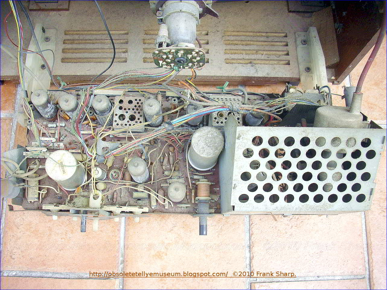

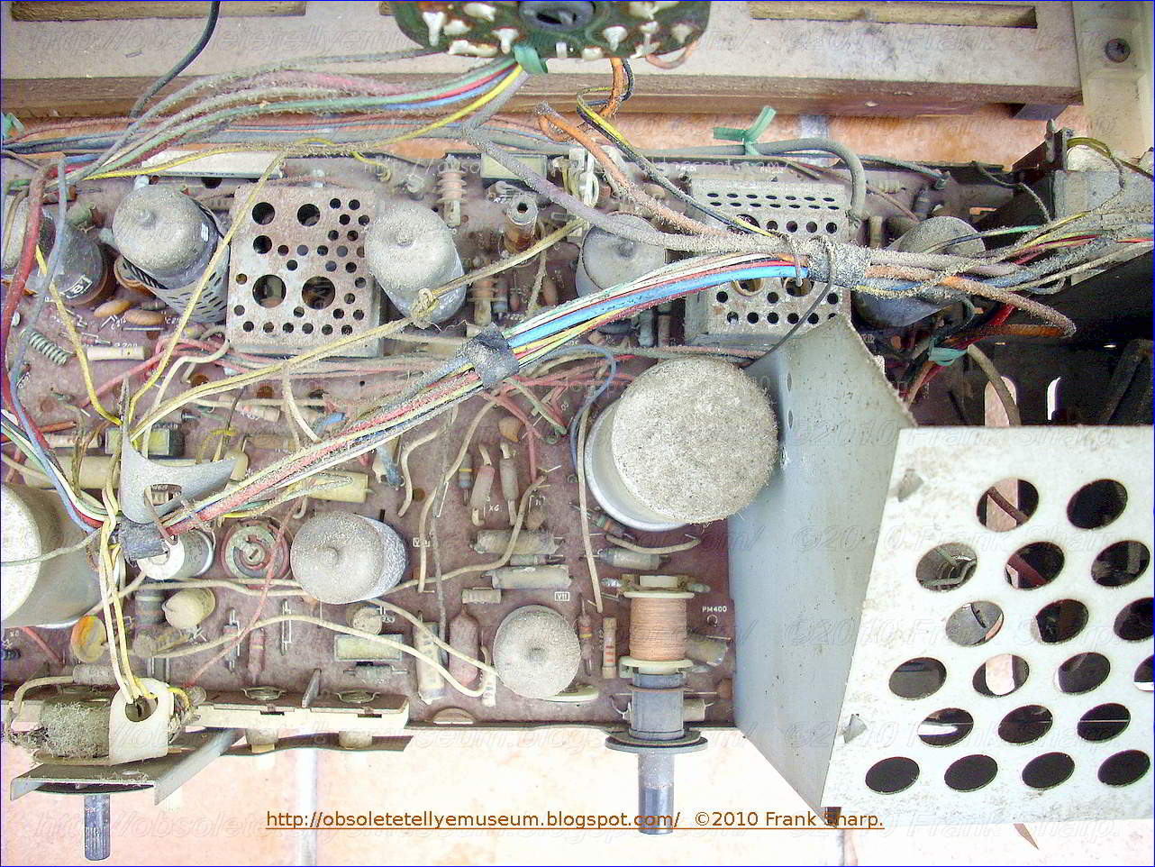


The TELEFUNKEN CHASSIS CHASSIS T582-2 is the successor of the previous series of chassis fitting bigger screen types.
On a PCB monocarrier type all parts are composing the receiver except tuners which are located on the left side.
The chassis is entirely based on tubes and is differently organized respect to other older types.
In this, the power supply is derived via big resistor from mains after rectifier instead of using a big power transformer.
TRANSISTORIZED UHF VARIABLE CAPACITOR TUNER EXAMPLE:
A continuously adjustable UHF tuner has a multi-compartmented housing
each of which has a tunable frequency selector. These selectors are
essentially identical to one another in respect of dimension and
configuration. Each is made up of a multi-turn inductor which, in
conjunction with the compartment walls, constitutes an approximately
quarter-wave transmission line at the high frequency end of the tuning
band and also of an adjustable capacitor for tuning the selector over a
band equal in width to the UHF band. The capacitor has both stationary
and movable electrodes. The former is an extension of an end turn of the
inductor and the latter has a main body portion and another portion
which is located at one end of the main body portion and is adjustable
transversely relative thereto. The movable electrode has a first extreme
position which is one of minimum capacitance and in which the aforesaid
other portion of the movable electrode is the predominant tuning
adjustment and is used to establish the high frequency end of the tuning
range. The other extreme or maximum capacitance position of the movable
electrode determines the low frequency end of the tuning range and a
control shaft permits displacement of the movable electrode between
these two extreme positions to tune the selector over its range.

2. A capacitor in accordance with claim 1 in which said other capacitor plate is configured to constitute said means.
3. A capacitor as defined in claim 1 wherein said one capacitor plate is provided with means forming calibrating electrodes and wherein said auxiliary part has a size and configuration different from that of said calibrating electrodes.
4. A capacitor as defined in claim 1, said capacitor being a rotary capacitor and said one capacitor plate being a rotatably mounted capacitor plate.
 This invention relates in general to wave signal tuners and
in particular to an improved continuous type tuner for the UHF
television band.
This invention relates in general to wave signal tuners and
in particular to an improved continuous type tuner for the UHF
television band. Under present allocations there are two rather widely spaced bands in the radio frequency spectrum which are reserved for television broadcasting. The first, a relatively low frequency band, is designated the VHF band and it accommodates twelve channels; five having frequency assignments between 54 and 88 megacycles and seven between 174 and 216 megacycles. The second band is the relatively high frequency UHF band which accommodates seventy television channels at 6 megacycle intervals between 470 and 890 megacycles.
In view of the relatively few (12) channels in the VHF band, either a turret or a switch type tuner, that is, a tuner having a discrete-stop or position for each channel, is feasible. Insofar as UHF is concerned, however, a discrete-stop tuner is obviously impractical because of the number of positions (70) that would be required. While tuning strips tailored to individual UHF channels are available for use in turret type VHF tuners, the total number of UHF and VHF stations that can be accommodated is limited, of course, to the number of strips which may be accommodated on the turret.
In view of the aforementioned mechanical considerations, the prior art has invariably resorted to a continuous type tuner for receivers designed to accommodate the entire UHF band. The frequency determining circuits for such tuners, however, pose special design problems since conventional lumped constant circuit elements, which ordinarily suffice at VHF, do not function properly at UHF. This is due to the fact that the physical dimensions of such components become an appreciable fraction of the wavelength of UHF signals, and particularly is this the case in the upper reaches of the UHF band. This, in turn, dictates recourse to distributed constant elements, such as tunable transmission lines, for use in the frequency determining circuits.
A conventional tuned-line UHF tuner of the type above-mentioned comprises one or more RF preselector stages, a vacuum tube oscillator stage and a mixer circuit which develops an IF or difference frequency signal by heterodyning a selected RF signal with the oscillator signal. It is conventional practice to use substantially identical quarter-wave transmission line elements, which are tuned by rotatably supported capacitor electrodes, in each of the preselector stages while employing a tunable half-wave line in the oscillator stage. While the operating frequency of the oscillator throughout most of its range is primarily controlled by the tuning capacitor, it is also conventional prior art practice to employ separate trimmer capacitors to insure that the upper and lower limits of the UHF range can be readily tuned. Specifically, when the tuning capacitor is positioned for minimum capacitance, one trimmer capacitor is adjusted to tune the oscillator to the high frequency end of the band. On the other hand, when the tuning capacitor is positioned for maximum capacitance, a second trimmer capacitor is adjusted so as to establish the lower frequency limit of the oscillator. In like fashion, the upper tuning range of the preselector stages is determined by a separate trimmer capacitor in each stage. All of these expedients, while effective, are undesirably costly and complex, both as to component requirements and assembly and alignment procedures in production.
It is therefore a principal object of the invention to provide a new and improved multi-stage UHF television tuner.
It is also an object of the invention to provide a UHF tuner construction which requires a minimum number of component parts.
It is another object of the invention to provide a continuous UHF television tuner of a unique and economical construction.
A continuously adjustable UHF tuner constructed in accordance with the invention comprises a housing which has a plurality of compartments each of which includes a signal translating stage. A control shaft extends through each of the compartments and is rotatably supported by the end walls of the housing. The tuner also includes a corresponding plurality of tunable frequency selector circuits, one for each stage and each comprising an inductor having an electrical length which approaches one quarter of a wavelength at the high frequency end of the UHF band. Each tunable circuit further includes a capacitor having a stationary electrode constituted by an extension of the inductor and an assigned pair of spaced electrodes which are affixed to the control shaft for rotational displacement from a position overlapping and embracing the stationary electrode to a position remote therefrom. All of the displaceable electrodes have a substantially identical configuration and at least one of each of the displaceable electrode pairs has an adjustable tab for establishing, in conjunction with its assigned stationary electrode, the principal tuning capacitance for its associated frequency selector circuits at the high frequency end of the UHF band.
The features of this invention which are believed to be novel are set forth with particularity in the appended claims. The invention, together with further objects and advantages thereof, may best be understood, however, by reference to the following description taken in conjunction with the accompanying drawings, in the several figures of which like reference numerals identify like elements, and in which:
FIG. 1 is an elevation view, in section, of a continuous type UHF television tuner embodying the invention;
FIG. 2 is a sectional view of the tuner taken along lines 2--2 of FIG. 1;
FIG. 3 is a detail view, partly in cross section, of one component of the UHF tuner shown in FIG. 1; and
FIG. 4 is a schematic diagram of the UHF tuner.
Referring now specifically to FIGS. 1 and 2, the continuously adjustable UHF tuner 10 shown therein comprises a metal housing 11 which encloses a plurality of signal translating stages. More particularly, tuner 10 includes first and second RF preselector stages 12, 13, respectively, separated by a compartment wall 14, and an oscillator stage 15 shielded from preselector 13 by a wall 16. A control shaft 17 extends through the compartments and is rotatably journaled upon bearings supported by the end walls 18, 19 of the housing. Shaft 17 is conductively connected to end walls 18, 19 and to compartment walls 14, 16 by a series of grounding leaves 20 each of which has one end soldered to a housing or compartment wall and an intermediate portion seated within an under cut portion of shaft 17, see FIG. 2.
Preselector stage 12 includes a tunable frequency selector circuit comprising an inductor 22 having an electrical length which approaches one quarter of a wave length at the high frequency end of the UHF band. One end of inductor 22 is conductively secured to the top wall 23 of housing 11 while the other end terminates in a planar extension 24 which is supported by a post 21 of insulating material, see FIG. 2. In this fashion inductor 22 constitutes the inner conductor of a coaxial transmission line while the housing and bordering walls form the outer conductor.
Extension 24 serves as the stationary electrode of a tuning capacitor which also includes a pair of spaced electrodes 26 which are soldered, staked or otherwise conductively affixed to control shaft 17 for rotational displacement in a plane parallel to stationary electrode 24 from a position overlapping and embracing the stationary electrode to a position remote therefrom. The latter position is illustrated in FIG. 2. Electrodes 26 are of identical arcuate configuration and each includes an adjustable tab 26', preferably struck or formed along one edge of the electrode itself. As will be explained more completely below, tabs 26' together with electrode 24 serve to establish the principal tuning capacitance for preselector 12 at the high frequency end of the UHF band. Additionally, each of electrodes 26 has a plurality of canted knifing slots 27 to facilitate tuning preselector 12 so that it will "track" or follow oscillator stage 15 when the latter is tuned across the UHF band.
Preselector 12 also includes an antenna input circuit comprising a pair of UHF antenna terminals 28 which are mounted on a panel 25 of insulating material atop housing 11 and are coupled to inductor 22 via a coil 29. One of terminals 28 is returned to a plane of reference potential, housing 11, through a resistor 30 which provides a leakage path for any static charge accumulating on the antenna.
The tunable frequency selector circuit for preselector 13 comprises an inductor 32 which is similar in length and configuration to inductor 22 and is coupled thereto through a window 33 in compartment wall 14. Inductor 32 also has one end grounded to top wall 23 of the housing and a free end formed into a planar extension 34 which is supported by a post 21 thus permitting inductor 32 to serve as the inner conductor of a coaxial transmission line of which compartment walls 14, 16 and housing 11 constitute the outer conductor. Extension 34 is of the same size and configuration as extension 24 and is in alignment therewith as viewed along shaft 17.
Preselector line 32 is tuned by a capacitor which includes inductor extension 34 as a stationary electrode and a pair of adjustable electrodes 36 which are conductively affixed to shaft 17 in axial alignment with electrodes 26 and displaceable over the same limits as electrodes 26. Electrodes 36 are identical in configuration to electrodes 26 even to the extent of having similar slots 27 and adjustable tabs 36' which, together with stationary electrode 34, constitute the principal tuning capacitance for preselector 13 at the high end of the UHF band.
Preselector compartment 13 further includes a mixer diode 35 having one lead connected to a tap on inductor 32 and a second lead protruding through an aperture 37 in compartment wall 16 to form a coupling loop 38 which is connected to the center lead of a feed-through capacitor 39 mounted in wall 16. An IF output coil 40 is connected between the center lead of feed-through capacitor 39 and the center terminal of an IF output jack 41. Jack 41 is coupled to a television receiver, now shown, via a coaxial cable 59.
As is apparent in FIG. 1, capacitor electrodes 26, 36 are mounted symmetrically relative to the walls of their respective compartments. This, of course, permits a measure of control over stray capacitances by equalizing the effects of the strays between the capacitor electrodes and the compartment.
On the other hand, inductors 22, 32 are not symmetrically disposed relative to their compartments in that their center sections are offset relative to their respective extensions 24,34. Although the inductors are substantially identical in length, inductor 32 constitutes, in effect, a mirror image of inductor 22 rather than being identical in configuration. In this fashion their electrode extensions 24, 34 remain centered in their respective compartments while the inductor portions assume positions which provide a desired magnitude of mutual coupling commensurate with the smallest feasible opening for window 33.
Oscillator stage 15 also includes a tunable frequency selector circuit comprising an inductor 42 having an electrical length approaching a quarter wave length at the high frequency end of the UHF band. The low impedance end of inductor 42 is coupled to wall 23 of the housing through a capacitor 43 while its opposite end is formed into a planar extension 44 which is supported by a post 21 and disposed in alignment with preselector extensions 24, 34. Inductor 42 together with housing 11 and walls 16, 19 form a third capacity-tuned co-axial transmission line. Except for the fact that its low impedance extremity is turned back to accommodate a connection to capacitor 43, see FIG. 1, inductor 42 is substantially identical in length and configuration to inductor 32. The tuning capacitor for the oscillator stage comprises inductor extension 44 as a stationary electrode and the pair of adjustable electrodes 46 which are conductively secured to shaft 17 in alignment with preselector electrodes 26, 36 for displacement in the same manner as those electrodes. While they do not have the canted knifing slots found in electrodes 26, 36, each of electrodes 46 does have a single tuning slot 47 which is located outside that area of the electrode which confronts stationary electrode 44 and is disposed normal to the straight edge of the electrode, see FIG. 3. In other respects, electrodes 46 are identical in configuration to preselector electrodes 26, 36 and, in like fashion, include adjustable tab portions 46' which cooperate with stationary electrode 44 to establish the tuning capacitance for the oscillator at the high frequency end of the UHF band.
As previously noted each of preselector stages 12, 13 and oscillator 15 also employ substantially identical inductors 22, 32 and 42, respectively. Therefore, insofar as the major components are concerned, the three stages are identical. It is appreciated, of course, that oscillator stage 15 must operate at a frequency which is displaced 40 megacycles from and preferably above, the operating frequency of the preselector stages. The oscillator stage maintains this frequency separation by virtue of capacitor 43 which is disposed in series relation with tuning capacitor 46, 46' thereby reducing the total capacitance of the oscillator stage and permitting tuning to a higher frequency.
The low impedance end of inductor 42 is directly connected to the output electrode or collector 49 of a grounded-base NPN transistor oscillator 50. By employing a low impedance oscillating device such as a transistor, a quarter-wave line or inductor is feasible. Collector 49 is connected to a source of unidirectional potential B+ via a decoupling choke 51, a feed-through capacitor 52 which is mounted in the top wall of housing 11, and a voltage dropping resistor 58. The emitter electrode 53 of transistor 50 is returned to reference potential housing 11, through a current-limiting bias resistor 54 which also serves to isolate the emitter from RF energy. The base or control electrode 55 is connected to B+ potential through a feed-through capacitor 56, a resistor 57 and resistor 58.
It is recognized, of course, that a PNP transistor can be substituted for transistor 50 simply by reversing the return connections of choke coil 51 and bias resistor 54. More particularly, such a substitution would merely entail returning collector choke 51 to reference potential and then connecting emitter resistor 54 through feed-through capacitor 52 to B+.
Located within the oscillator compartment is a range or limit control comprising a post 60 anchored to compartment wall 16 and a stop 61 which is affixed to shaft 17 and includes a pair of abutments 62, 63 which cooperate with post 60 to confine the rotation of shaft 17 to an angular displacement of approximately 200°, the travel required by capacitor electrodes 26, 36, 46 to tune their associated inductors across the UHF band.
UHF tuner 10 is actuated by a viewer control knob which is coupled to shaft 17 through a conventional gear reduction and vernier mechanism, now shown. Initially, however, tuner 10 must be set-up or phased by a test procedure which establishes the correct tuning range for each of the several stages. An acceptable procedure entails energizing transistor 50 and then rotating shaft 17 counterclockwise, as viewed in FIG. 2, until abutment 62 of the limit control encounters post 60. Transistor 50 functions as a conventional grounded-base oscillator and develops an output signal across frequency determining circuit 42, 44, 46. RF oscillator energy is coupled from this circuit to mixer diode 35 through loop 38. With shaft 17 so positioned, oscillator inductor 42 is tuned, principally by adjusting the proximity of electrode tabs 46' to electrode 44, to a frequency near the high end of the UHF band.
The frequency range of the oscillator is then adjusted by coupling the output of a sweeping generator to antenna terminals 28. In addition to an UHF signal varying in frequency above and below UHF channel 83, the output of the sweeping generator also includes a marker pulse which identifies the video carrier for channel 83. This sweeping signal is coupled to inductor 22 of preselector 12 through coil 29 and from there to inductor 32 of preselector 13 through coupling window 33. A portion of this signal is also injected into mixer diode 35 by virtue of the tap on inductor 32. To the output of diode 35 is externally added a pair of markers which are separated by 41/2 megacycles and represent video and sound IF carriers. This composite signal is then externally detected and applied to the terminals of an oscilloscope. The displayed pattern shows the channel 83 marker, as well as the sound and video IF carriers, and also gives an indication of the pass band of preselector stages 12 and 13. The frequency of oscillator 15 is adjusted for the high end of the UHF band by positioning electrode tabs 46' relative to electrode 44 until the channel 83 marker on the scope pattern is properly disposed in relation to the sound and video IF markers. The pass bands of preselectors 12, 13 are then adjusted by positioning their respective electrode tabs 26', 36' relative to electrodes 24, 34 until a desired pass band is displayed on the scope.
The oscillator is next adjusted for the low end of the band by rotating tuning shaft 17 until stop abutment 63 engages post 60. The previously described procedure is then repeated using a sweep signal centered about UHF channel 14. The oscillator frequency is now adjusted by inserting a tuning wand in slots 47 of electrodes 46 and positioning those electrodes relative to electrode 44 until the scope pattern reveals proper oscillator frequency at the low end of the band.
Tracking of the oscillator across the UHF band by the preselector stages is then checked by returning tuning shaft 17 to the channel 83 position. Tracking is accomplished by successively positioning control shaft 17 to tune in a series of stations in the UHF band. More particularly, shaft 17 is rotated clockwise, as viewed in FIG. 2, to a position corresponding to UHF channel 75, for example, at which station a sweep signal having a frequency centered about that channel is coupled to antenna terminals 28. Preselector stages 12, 13 are then "tracked" to the oscillator by inserting a tuning wand alternately in the slots 27 of capacitor electrodes 26, 36 and bending the section of the electrode adjacent the slot, i.e., "knifing" the rotor elements, until a pattern of desired band pass is displayed on the oscilloscope. Control shaft 17 is then rotated to another position where the above procedure is repeated a second time. The knifing procedure is repeated for as many channels as is required to achieve proper tracking of the preselector circuits.
As shown prior art trimmer type capacitors are eliminated by resort to the disclosed electrode-tab arrangement in the frequency determining circuits of the several stages. Moreover, a substantial economy is achieved by forming electrodes 26, 36 and 46 from the same tool. This procedure also eliminates any tuning discrepancies attributable to differences in electrode size or configuration. Moreover, by forming these electrodes from the same tool any change in electrode size or configuration due to tool wear will not affect one stage any differently than any other since all the electrodes will retain an identical shape and configuration.
In another aspect, section 12, for example,
of the UHF tuner of the present invention comprises a variable capacitor
including cooperating rotor and stator capacitor plates 26 and 24
respectively, the rotor plates 26 being mounted for rotary movement with
respect to stator plate 24 between a first position wherein the
capacitance of the capacitor is at a minimum and a second position
wherein the capacitance of the capacitor is at a maximum. Each of the
rotor plates 26 has a main part and an auxiliary part 26', and only the
auxiliary part of the rotor plate 26 is opposite the stator plate 24
when the capacitor is in its minimum capacity position. Auxiliary parts
26' of rotor plate 26 is adjustable toward and away from the stator
plate 24, thereby to allow the minimum capacitance of the capacitor to
be adjusted. Auxiliary part 26' of rotor plate 26 is not opposite stator
plate 24 when the capacitor is in its maximum capacity position. The
variable capacitor further comprises means for preventing an abrupt
change in the capacitance characteristic of the capacitor at the point
where auxiliary part 26' of rotor plate 26 ceases to be opposite stator
plate 24, such means constituting the bottom tapered edge of stator
plate 24 which is non-parallel or forms an angle with the edge of
auxiliary part 26' of rotor plate 26 as the rotor is turned clockwise to
the point that auxiliary part 26' departs from confronting relationship
with stator plate 24. It will be observed that rotor plates 26 are
provided with means in the form of slots 27 to form calibrating
electrodes, and that auxiliary part 26' has a size and configuration
different from that of any of the individual calibrating electrodes. By the same token resort to a low impedance device for the oscillator stage, transistor 50, permits use of substantially identical tuned quarter-wave lines, inductors 22, 32, 42, in each frequency selector circuit. The savings which accrue as a result of employing substantially identical components in each of the three stages of the tuner contribute not only to economy in component cost but also a reduction in labor cost because of the resultant simplicity in manufacturing the tuner.
While a particular embodiment of the present invention has been shown and described, it is apparent that changes and modifications may be made therein without departing from the invention in its broader aspects. The aim of the appended claims, therefore, is to cover all such changes and modifications as fall within the true spirit and scope of the invention.
- Inventors:REYNOLDS WAYNE H
- Assignee:ZENITH RADIO CORP.

TELEFUNKEN TUBES HORIZONTAL DEFLECTION CIRCUIT

The present invention relates to deflection circuits of the type employed for providing a time base in connection with cathode ray tubes for deflection of an electron beam.
Magnetic deflection systems are often employed in present day systems for deflecting an electron beam in a cathode ray tube. These magnetic deflection systems employ in general two coils arranged about the neck of the cathode ray tube and in which coils saw tooth wave forms of different frequencies are generated. In one arrangement for generating saw tooth current wave forms for line deflection of TV picture tubes and with which arrangement the present invention may be advantageously used, a condenser is provided which by means of a diode which is rendered conductive during the forward stroke of the saw tooth wave form, supplies a constant voltage to the winding of an auto transformer. By means of this constant voltage, a linearly increasing current is generated in the transformer and as a result also in the deflection coil coupled thereto. The loss of energy in the deflection circuit is corn-pensated during the forward stroke of the saw tooth wave form by the final sweep amplifier, which supplies such a current !that the diode conducts during the entire for-ward stroke of the saw tooth wave form. The diode is rendered non-conductive when current flow through the final sweep amplifier is cut-off by a saw tooth synchroniz-ing impulse fed to the control grid of the final sweep amplifier tube. In particular, the final sweep amplifier is cut-off by the negative flyback of a saw tooth synchronizing impulse fed to its control grid. When


The amount of deflection of the electron beam in a cathode ray tube depends not only on the amplitude of the saw tooth current wave form that flows through the deflection coil but also on the amplitude of the accelerate 5 ing voltage to which the electron beam is exposed. Since the saw tooth current wave form and the accelerating voltage are produced in the same circuit, it is obvious that an adjustment, of, for instance, the amplitude of the saw tooth current wave form will produce a con 10 comittant change in amplitude of the aLcelerating volt-age. The sweep amplitude is, on the one hand, directly proportional to the deflection current flowing through the deflection coil, and on the other hand, inversely propor-tional to the square root of the accelerating voltage. 15 It is often desired to regulate the sweep amplitude with-out affecting the focus of the electron beam on the screen of the image tube. This may be performed by ad-justing the sweep current amplitude while at the same time maintaining the high voltage, which is obtained dure 20 ing the fly back period, constant. On the other hand it may also be desired to adjust the focus of the electron beam on the screen of the picture tube. This focus adjustment may be performed by changing the magnetic field strength of a focussing magnet used with magnetical-25 ly focussed cathode ray tubes. If one, however, desires to employ a permanent magnet without additional focus-ing coils or without the necessity of adjusting the mag-netic field strength, the beam may be focussed by chang-ing the value of the accelerating voltage. However, as 30 already pointed out, a change in accelerating voltage will produce a change in the sweep amplitude, which is in-versely proportional to the square root of the accelerating voltage. Two ways are known for making the desired adjust-35 ment of the sweep amplitude. The first way concerns the adjustment of the fly back time, on which the magni-tude of the generated high voltage as well as the deflec-tion amplitude is dependent. The second way concerns the changing of the regulated anode voltage of the final 40 sweep amplifier tube in which case, the saw tooth ampli-tude will be directly proportional to the accelerating volt-age. In order to maintain a predetermined amplitude of the sweep, the saw tooth current must change as the square root of the accelerating voltage. With this rela-45 tionship of sweep current and accelerating voltage, a change in the size of the raster will result with changes in sweep amplitude. The adjustment of the anode voltage may be made, 'as known in the art, by means of a variable resistor con-50 nected in series with the anode supply voltage. The dis-advantage of adjusting the anode voltage with the above mentioned variable resistor lies in the fact that a certain amount of power will be dissipated by the resistor, thus requiring a higher initial anode supply If oltage. One of 55 the objects of the present 'invention is to provide a control arrangement for adjusting the anode voltage of the final sweep amplifier tube in such manner that additional power requirements are unnecessary. This is accomplished by making a variable c
onnection of the anode of the final 60 sweep amplifier tube with a transformer. A uniform. adjustment is made possible by coupling the final sweep amplifier tube parallel to a portion of the transformer winding by means of two series connected inductances. The anode of the final sweep amplifier tube is connected 65 to the junction of the inductances, while the free terminals of the inductances are connected across a portion of the transformer winding, at least one of the series connected inductances being variable. With this arrangement, the two inductances can be adjusted in such manner that the 70 'total inductance of the two series connected inductances always remains constant over the adjusting range. Where the total inductance of the series connected inductances
remains constant over the adjusting range, a change in Fig. 6 shows a modification of the circuit arrangement fly back time will occur with anode voltage adjustments of Fig. 1; inasmuch as the tube capacity is transformed at the de- Fig. 7 shows yet another modification of the circuit flection coil into a greater or smaller value with the ad- arrangement of Fig. 1; and justment of the adjustable inductances. 5 Fig. 8 shows yet other curves having characteristics dif-The adjusting arrangement may on the other hand be ferent from those illustrated in Figs. 3 and 4. _so designed that the total inductanc
 e
of the series con- Fig. 1 shows one example of a circuit in
accordance nected variable inductances instead of being held con- with
the invention and serves for explaining the opera-stant, as
described above, may be so dimensioned that the tion of the circuit
in accordance with the invention. It total inductance value varies in
the same sense, or direc- 10 is assumed that the condenser is
charged ± and — as tion, as the inductance which has its free end
terminal shown in Fig. 1. The diode 2, during the forward stroke
_connected to the higher alternating voltage point on the of the
synchronizing impulse supplied by the sweep gen-_transformer. In this
case the fly back time will remain erator 5', connects a
substantially constant voltage to the constant with an adjustment of
the anode voltage so that transformer winding 3 which is illustrated
as being an a sharp anode voltage adjustment can be made. 15 auto
transformer. As a result of the constant voltage _ In order to obtain
other arbitrary adjusting charac- connected to the transformer a
linearly increasing cur-teristics, it is possible to connect, for
instance, at least rent is generated in the transformer winding 3 as
well as in one capacitor in parallel with at least one of the two
the deflecting coil 4 which is coupled to the winding 3. series
connected inductances. The loss of energy in the circuit is
compensated during . From the above discussion it will be apparent
that 20 the forward stroke of the synchronizing by the final sweep it
is an object of the present invention to provide a beam amplifier
5. The amplifier 5 supplies such a current deflection circuit for
cathode ray tubes in which the to the transformer that the diode tube
2 conducts during sweep amplitude and the high direct current
voltage, the entire forward stroke of the synchronizing impulse.
generated in the beam deflection circuit, may be inde- When the tube 5
is cut off by the negative fly back por-pendently adjusted. 25 tion
of the synchronizing impuse which has an approxi-It is yet another
object of the present invention to mately saw tooth wave form, the
diode 2 will likewise be provide a beam deflection circuit for
cathode ray tubes cut off. As a result the transformer 3 as well as
the de-in which the sweep amplitude may be varied linearly with
fleeting coil 4 and stray capacities in the circuit go through
relation to the high direct current voltage. a free half cycle
variation, at the end of which the volt-It is yet another object of
the present invention to pro- 30 age across the transformer is
reversed, and as a result the vide a beam deflection circuit for
cathode ray tubes in control diode 2 is again permitted to conduct.
The en-which the electron beam focus may be changed by ad- tire cycle
is again repeated when the forward stroke of the justing the
accelerating voltage without changing, when next syunchronizing impulse
reaches the control grid 1' so desired, the sweep amplitude. of the
final sweep amplifier tube 5. In addition, during Yet another
object of the present invention is to pro- 35 The fly back period of
the saw tooth synchronizing im-vide a beam deflecting circuit for
cathode ray tubes in pulse, a high positive peaked voltage is
developed across which the fly-back time may be accurately
controlled. the transformer winding 6 which is rectified by diode 7.
With the above objects in view the present invention The
inductances 8 and 9 are connected in series, the mainly consists of a
deflection circuit for generating in free terminals of the
inductances 8 and 9, henceforth also an inductance a current having a
saw tooth wave form 40 referred to as first and second inductances,
respectively, and for simultaneously generating a high direct
current being connected across another portion 12 of the
trans-voltage, comprising, a condenser adapted to have a direct
former 3. The first and second inductances are of the current
voltage across its terminals, switching means con- type which may be
adjusted in opposite direction so that nected in series with the
condenser for applying the volt- the tot
e
of the series con- Fig. 1 shows one example of a circuit in
accordance nected variable inductances instead of being held con- with
the invention and serves for explaining the opera-stant, as
described above, may be so dimensioned that the tion of the circuit
in accordance with the invention. It total inductance value varies in
the same sense, or direc- 10 is assumed that the condenser is
charged ± and — as tion, as the inductance which has its free end
terminal shown in Fig. 1. The diode 2, during the forward stroke
_connected to the higher alternating voltage point on the of the
synchronizing impulse supplied by the sweep gen-_transformer. In this
case the fly back time will remain erator 5', connects a
substantially constant voltage to the constant with an adjustment of
the anode voltage so that transformer winding 3 which is illustrated
as being an a sharp anode voltage adjustment can be made. 15 auto
transformer. As a result of the constant voltage _ In order to obtain
other arbitrary adjusting charac- connected to the transformer a
linearly increasing cur-teristics, it is possible to connect, for
instance, at least rent is generated in the transformer winding 3 as
well as in one capacitor in parallel with at least one of the two
the deflecting coil 4 which is coupled to the winding 3. series
connected inductances. The loss of energy in the circuit is
compensated during . From the above discussion it will be apparent
that 20 the forward stroke of the synchronizing by the final sweep it
is an object of the present invention to provide a beam amplifier
5. The amplifier 5 supplies such a current deflection circuit for
cathode ray tubes in which the to the transformer that the diode tube
2 conducts during sweep amplitude and the high direct current
voltage, the entire forward stroke of the synchronizing impulse.
generated in the beam deflection circuit, may be inde- When the tube 5
is cut off by the negative fly back por-pendently adjusted. 25 tion
of the synchronizing impuse which has an approxi-It is yet another
object of the present invention to mately saw tooth wave form, the
diode 2 will likewise be provide a beam deflection circuit for
cathode ray tubes cut off. As a result the transformer 3 as well as
the de-in which the sweep amplitude may be varied linearly with
fleeting coil 4 and stray capacities in the circuit go through
relation to the high direct current voltage. a free half cycle
variation, at the end of which the volt-It is yet another object of
the present invention to pro- 30 age across the transformer is
reversed, and as a result the vide a beam deflection circuit for
cathode ray tubes in control diode 2 is again permitted to conduct.
The en-which the electron beam focus may be changed by ad- tire cycle
is again repeated when the forward stroke of the justing the
accelerating voltage without changing, when next syunchronizing impulse
reaches the control grid 1' so desired, the sweep amplitude. of the
final sweep amplifier tube 5. In addition, during Yet another
object of the present invention is to pro- 35 The fly back period of
the saw tooth synchronizing im-vide a beam deflecting circuit for
cathode ray tubes in pulse, a high positive peaked voltage is
developed across which the fly-back time may be accurately
controlled. the transformer winding 6 which is rectified by diode 7.
With the above objects in view the present invention The
inductances 8 and 9 are connected in series, the mainly consists of a
deflection circuit for generating in free terminals of the
inductances 8 and 9, henceforth also an inductance a current having a
saw tooth wave form 40 referred to as first and second inductances,
respectively, and for simultaneously generating a high direct
current being connected across another portion 12 of the
trans-voltage, comprising, a condenser adapted to have a direct
former 3. The first and second inductances are of the current
voltage across its terminals, switching means con- type which may be
adjusted in opposite direction so that nected in series with the
condenser for applying the volt- the tot al
inductance L8 plus L9 remains constant over the age across the
terminals of the condenser to the induct- 45 entire adjusting range.
This adjustment can be effected, ance when the switching means is
actuated, a transformer for instance, by winding both coils on a common
cylin-having a winding a first portion of which is coupled with
drical coil form having an axial bore. Within the bore the inductance,
an amplifier having an anode, the ampli- may be arranged a movable
ferro-magnetic core. By fier controlling the operation of the
switching means, and varying the position of the core in the coil form
the in-a first and a second inductance connected in series to 50
ductance of one coil will increase while the inductance of form a
junction to which the anode of the amplifier tube the other will
decrease. is connected, the end terminals of the first and second Fig.
2 shows curves exemplifying the different voltage inductances being
connected across a second portion of relationships between
accelerating voltage and deflec-the transformer winding, at least one
of-the inductances tion coil voltage that may be obtained for
definite rela-being variable over a predetermined adjusting range. 55
tionships between the first and second inductances. Usp The novel
features which are considered as charac- represents the voltage at
the deflection coil 4 obtained teristic of the invention are set
forth in particular in during the forward stroke of a saw tooth wave
form, and the appended claims. The invention itself, however, both
is plotted along the abscissa. Ux represents the high volt-as to its
construction and its method of operation, together age generated at
terminal H and is plotted along the ordi-with additional objects
and advantages thereof, will be 60 nate axis. The high voltage when
appropriately con-best understood from the following description of
specific nected to a cathode ray tube serves to accelerate the
elec-embodiments when read in connection with the accom- tron beam in
the cathode ray tube. If the dimensions panying drawings, in which:
of the adjustable inductances are chosen so that the Fig. 1 shows a
circuit diagram of a deflection circuit in total inductance LB plus
L9 is not maintained constant, but accordance with the present
invention: 65 is instead varied in such manner that the total
inductance Fig. 2 shows the various curves obtained by plotting
varies in the same sense as does the inductance Ls so that the voltage
at the deflection coil versus the accelerating the transformed tube
capacity at the deflection coil 4 is voltage at terminal H in the
circuit arrangement of Fig. 1; compensated, then the fly back time
will remain constant Fig. 3
shows the curves obtained by plotting the varia- during the
adjustment. Curve 21. shown in Fig. 2 shows tions in inductance versus
core displacement of a control 70 the adjusting characteristic
curve obtained with the last arrangement in accordance with the
invention; mentioned relationship of the inductances L8 and Ls. Fig.
4 shows another set of curves having different char- The high
voltage UH is seen to increase linearly with re-acteristics from those
illustrated in Fig. 3; spect to the deflection amplitude. Curve 22
shows the - Fig. 5 shows schematically, a control arrangement used
deflection amplitude Up as varying with the square root in a
deflection circuit, in accordance with the invention; 75 of the high
voltage UH. As may be noted from curve 22,
al
inductance L8 plus L9 remains constant over the age across the
terminals of the condenser to the induct- 45 entire adjusting range.
This adjustment can be effected, ance when the switching means is
actuated, a transformer for instance, by winding both coils on a common
cylin-having a winding a first portion of which is coupled with
drical coil form having an axial bore. Within the bore the inductance,
an amplifier having an anode, the ampli- may be arranged a movable
ferro-magnetic core. By fier controlling the operation of the
switching means, and varying the position of the core in the coil form
the in-a first and a second inductance connected in series to 50
ductance of one coil will increase while the inductance of form a
junction to which the anode of the amplifier tube the other will
decrease. is connected, the end terminals of the first and second Fig.
2 shows curves exemplifying the different voltage inductances being
connected across a second portion of relationships between
accelerating voltage and deflec-the transformer winding, at least one
of-the inductances tion coil voltage that may be obtained for
definite rela-being variable over a predetermined adjusting range. 55
tionships between the first and second inductances. Usp The novel
features which are considered as charac- represents the voltage at
the deflection coil 4 obtained teristic of the invention are set
forth in particular in during the forward stroke of a saw tooth wave
form, and the appended claims. The invention itself, however, both
is plotted along the abscissa. Ux represents the high volt-as to its
construction and its method of operation, together age generated at
terminal H and is plotted along the ordi-with additional objects
and advantages thereof, will be 60 nate axis. The high voltage when
appropriately con-best understood from the following description of
specific nected to a cathode ray tube serves to accelerate the
elec-embodiments when read in connection with the accom- tron beam in
the cathode ray tube. If the dimensions panying drawings, in which:
of the adjustable inductances are chosen so that the Fig. 1 shows a
circuit diagram of a deflection circuit in total inductance LB plus
L9 is not maintained constant, but accordance with the present
invention: 65 is instead varied in such manner that the total
inductance Fig. 2 shows the various curves obtained by plotting
varies in the same sense as does the inductance Ls so that the voltage
at the deflection coil versus the accelerating the transformed tube
capacity at the deflection coil 4 is voltage at terminal H in the
circuit arrangement of Fig. 1; compensated, then the fly back time
will remain constant Fig. 3
shows the curves obtained by plotting the varia- during the
adjustment. Curve 21. shown in Fig. 2 shows tions in inductance versus
core displacement of a control 70 the adjusting characteristic
curve obtained with the last arrangement in accordance with the
invention; mentioned relationship of the inductances L8 and Ls. Fig.
4 shows another set of curves having different char- The high
voltage UH is seen to increase linearly with re-acteristics from those
illustrated in Fig. 3; spect to the deflection amplitude. Curve 22
shows the - Fig. 5 shows schematically, a control arrangement used
deflection amplitude Up as varying with the square root in a
deflection circuit, in accordance with the invention; 75 of the high
voltage UH. As may be noted from curve 22,a change in accelerating voltages Uit produces substan- ductances. Ls and L9 were adjusted in opposite direction, tially no change of the deflection amplitude. If the total that- is as the inductance of one increased the inductance inductance change is more pronounced than that used for of the other decreased, by means of a common high fre-obtaining curve 21, then the fly back time will change quency core. An independent adjustment of high voltage when an adjustment of the sweep amplitude is made. 5 and deflection amplitude could also be obtained, however, Curve 21 can be transformed into curve 23 if so desired, by an arrangement wherein the two inductances are sep-in which case, an adjustment of the inductances will arated and form two mutually independent coils each of produce no change in the high voltage UH. The man- which is variable. In this case the oppositely directed ner in which this is accomplished will be explained here- adjustment of the first and second inductances is some-inafter. 10 what more difficult to perform since in, this case, the ad-Fig. 3 illustrates in curve form the variations of the in- justment of the two inductances must be simultaneously dividual coil inductances L8, L9 as well as the variation of made. This is however no limitation since the adjust total inductance, Ls, plus L9, with relation to core ment is not made very often during actual operation. displacement X, as obtained with the circuit arrange- Fig. 7 shows yet another embodiment of the present ment of Fig. 1. It is apparent from Fig. 3 that the 15
milar
to that of instead with any other type of standard transformer.
Fig. 1 in all other respects. The inductance 13 makes it It will be
understood that each of the elements de-possible to adjust the
horizontal sweep amplitude while scribed above, or two or more
together, may also find a the high: voltage is maintained at a
constant level. useful application in other types of deflection
circuits in all of the arrangements described up to now the in- 75
differing from the types described above.While the invention has been illustrated and described 'as embodied in magnetic deflection circuits, it is not in--tended to be limited to the details shown, since various 'modifications and structural changes may be made with-out departing in any way from the spirit of the present invention. . Without further analysis, the foregoing will so fully reveal the gist of the present invention that others can by applying current knowledge readily adapt it for vari-ous applications without omitting features that, from the standpoint of prior art, fairly constitute essential charac-leristics of the generic or specific aspects of this inven-tion and, therefore, such adaptations should and are in-tended to be comprehended within the meaning and range of equivalence of the following claims. 7_ What is claimed as new and desired to be secured by Letters Patent is: 1 1. A deflection circuit for generating in an inductance _a current having a sawtooth wave form and for simul- taneously generating a high direct current voltage, corn- , . -prising in combination, a condenser adapted to have a rdirect current voltage across its terminals; switching means connected in series with said condenser for ap-plying said voltage across said terminals of said con-'denser to the inductance when said switching means is -actuated; a transformer having a winding a first portion of which is coupled with the inductance; an amplifier having an anode, said amplifier controlling the operation of said switching means; and a first and a second in-ductance connected in series to form a junction to which -said anode of said amplifier tube is connected, the end terminals of said first and second inductances being con-nected across a second portion of said transformer wind-ing, at least one of said first and second inductances _being variable over a predetermined adjusting range. 2. A deflection circuit for generating in a first in--ductance a current having a saw tooth wave form and for simultaneously generating a high direct current voltage, comprising in combination, a condenser adapted to have a direct current voltage across its terminals; switching means connected in series with said condenser for ap-plying said voltage across said terminals of said con-denser to the first inductance when said switching means is actuated; a transformer having a winding a first por-tion of which is coupled with the first inductance; an amplifier tube having an anode and controlling the opera-tion of said switching means; and a pair of adjustable inductances connected in series to form a junction to which said anode of said amplifier tube is connected, the end terminals of said pair of inductances being con-nected across a second portion of said transformer wind-ing, said pair of inductances being arranged with respect -to each other to be simultaneously adjustable in op-posite directions so as to yield a total inductance which is constant over the entire adjusting range. 3. A deflection circuit for generating in an inductance a current having a sawtooth wave form and for simul-taneously generating a high direct current voltage, com-prising a combination, a condenser adapted to have a di-rect current voltage across its terminals; switching means connected in series with said condenser for applying said voltage across said terminals of said condenser to the inductance when said switching means is actuated; a trans-former having a winding a first portion of which is coupled with the inductance; an amplifier having an anode, said amplifier controlling the operation of said switching means; a first and a second inductance connected in series to form a junction to which said anode of said amplifier tube is connected, the end terminals of said first and second inductances being connected across a second por-tion of said transformer winding, at least one of said first and second inductances being variable over a pre-determined adjusting range; and at least one condenser
connected across at least one of said inductances for se-lecting a desired adjusting curve. 4. A deflection circuit for generating in an inductance a current having a saw tooth wave form and for simul-taneously generating a high direct current voltage, comprising in combination, a condenser adapted to have a direct current voltage across its terminals; switching means connected in series with said condenser for applying said voltage across said terminals of said condenser to the inductance when said switching means is actuated; a transformer having a winding a first portion of which is coupled with the inductance; an amplifier having an anode, said amplifier controlling the operation of said switching means; a first and a second inductance connected in series to form a junction to which said anode of said amplifier tube is connected, the end terminals of said first and second inductances being connected across a second por-tion of said transformer winding, at least one of said first and second inductances being variable over a predeter-mined adjusting range; and a third adjustable inductance connected in parallel with one of said first and second inductances. 5. A deflection circuit for generating in a first induc-tance a current having a saw tooth wave form and for simultaneously generating a high direct current voltage, comprising in combination, a condenser adapted to have a direct current voltage across its terminals; switching means connected in series with said condenser for apply-ing said voltage across said terminals of said condenser to the first inductance when said switching means is actuated; a transformer having a winding a first portion of which is coupled with the first inductance; an amplifier tube hay-ing an anode and controlling the operation of said switch-ing means; and a pair of adjustable inductances connected in series to form a junction to which said anode of said amplifier tube is connected, the end terminals of said pair of inductances being connected across a second portion of said transformer winding, said pair of inductances being arranged with respect to each other to be simul-taneously adjustable in opposite directions so as to yield a total inductance which is constant over the entire ad-justing range, said pair of inductances forming control means for changing the amplitude of the sawtooth wave form while the high direct current voltage remains sub-stantially constant. 6. A deflection circuit for cathode ray tubes employing electro-magnetic deflecting coils comprising, in combina-tion, an output transfoi mer, the electro-magnetic deflect-ing coils being coupled to a first portion of said output transformer; a switching diode; a boost condenser, said diode and said condenser being connected in series across a second portion of said output transformer to develop across said boost condenser a voltage representative of recovered energy cyclically stored in the deflection cir-cuit; a deflection output tube having at least an anode and a cathode; a first and a second inductance connected in series to form a junction, the end terminals of said first and second inductances being connected across a third portion of said output transformer, the junction of said first and second inductances being connected to the anode of said deflection output tube, said inductances having windings adapted to be wound about a tubular coil form; and a high frequency core adapted to be slidably mounted inside the tubular coil form to change the in-ductance values of said two inductances in opposite di-rections. 7. A deflection circuit for cathode ray tubes employ-ing electromagnetic deflecting coils comprising, in com-bination, an output transformer; a deflection output tube, having at least an anode and a cathode, the electromag-netic deflecting coils being coupled to the anode-cathode circuit of said output tube through said output transform-er; a switching diode; a boost condenser, said diode and said condenser being connected in series across a first
portion of said output transformer to develop across said boost condenser a voltage representative of recovered energy cyclically stored in the deflection circuit; and means for adjusting the amplitude of the deflection volt-age for the cathode ray tubes, said means including a 5 pair of inductances connected in series across a second portion of said output transformer and having a junction point, the anode of said deflection output tube being con-nected to said junction point, at least one of said series con-nected inductances being adjustable to provide a variable 10 coupling between said output tube and said output trans-former. 8. A deflection circuit for cathode ray tubes employing electro-magnetic deflecting coils comprising, in combina-tion, an output transformer, the electromagnetic deflecting 15 coils being coupled to a first portion of said output trans-former; a switching diode; a boost condenser, said diode and said condenser being connected in series across a second portion of said output transformer to develop across said boost condenser a voltage representative of 20 recovered energy cyclically stored in the deflection circuit; a deflection output tube having at least an anode and a cathode; a first and a second inductance connected in series to form a junction, the end terminals of said first and second inductances being connected across a third por-ton of said output transformer, the junction of said first and second inductances being connected to the anode of said deflection output tube; means for adjusting at least one of said first and said second inductances to vary the inductance thereof through a predetermined range; and a first and second condenser connected respectively across
said first and second inductances for selecting a desired inductance adjusting curve. 9. A deflection circuit for cathode ray tubes employing electromagnetic deflecting coils comprising, in combina-tion, an output transformer; a deflection output tube, having at least an anode and a cathode, the electromag-netic deflecting coils being coupled to the anode-cathode circuit of said output tube thrcugh said output transformer; a switching diode; a boost condenser, said diode and said condenser being connected in series across a first por-tion of said output transformer to develop across said boost condenser a voltage representative of recovered energy cyclically stored in the deflection circuit; rectifier means connected to a winding of said output transformer to derive a high voltage from voltage pulses cyclically arising in said output transformer; and means for adjust-ing the amplitude of the deflection voltage for the cath-ode ray tubes, said means including a pair of inductances connected in series across a third portion of said output transformer and having a junction point, the anode of said deflection output tube being connected to said junc-tion point, said pair of inductances being simultaneously adjustable in opposite directions to give a total inductance which is constant over the entire adjusting range.
cathode ray tubes which generate saw tooth current curves,
and especially for the vertical deflection of one or several
electron beams in the picture tube of a television receiver,
wherein during the forward cource of the saw tooth curve
the ohmic voltage is high compared to the inductive volt‑
age.
In some cathode ray tube (CRT) circuits, the deflecting
coils at the line frequency, during the forward deflection
of the saw tooth deflecting current, are mostly inductive.
This is not true for the lower frequencies of vertical de‑
flection. In the latter case, the deflecting coils provide a
substantially ohmic resistance having but a small inductive
component. However this is not always true with the more
rapid fly-back pulse.
To produce a linear increase of the coil current during
forward deflection, a linear increase of the coil voltage
is also necessary. This increase is provided by a tube
either coupled directly I to the coil or through a trans‑
former. The control voltage is produced by an RC-circuit
which discharges through a tube, such as a blocldng oscil‑
lator. When using transformer coupling, it is usual to
employed relatively small transformers, for reasons of
economy, and because of this the deflecting current curve
in the coils deviates considerably from a saw tooth curve.
It is known that in order to achieve a linear rising flank
Of the saw tooth current curve, it is advantageous to pro‑
vide the charging capacitor with a frequency dependent
negativeS feedback from the transformer or from the anode
circuit of the tube. Such a negative feedback has been 40
provided in known circuits by means of a capacitive volt‑
age divider connected between the transformer, or anode,
and the charging capacitor. The tapping point of this volt‑
age divider is connected to a point of substantially axed
voltage through one or several resistors. By a substantial- 45
ly fixed voltage, is meant a voltage which has only slight
fluctuations with respect to the voltage which has only
slight fluctuations with respect to the voltage on the other
side of the resistance. The capacitive voltage divider is ,n
so designed that the first • capacitor in the negative feed-
back path, together with the resistance connected in the
shunt path forms a differentiating section which reduces
the negative feedback for the lower frequencies. By this
means the defects and deviations from a saw tooth curve r„
brought about by the finite inductance of the transformer,
are corrected. The remainder of the capacitive voltage
divider forms an integrating section which renders the neg‑
afive feedback voltage proportional to the current flowing
in the deflecting coils and filters out the fly-back peaks.
When using a CRT having a radius of screen c
 urvature 60
which is greater than the distance from the screen to the
center of deflection of the vertical deflecting coils, there
is tangent error (flat screen) distortion. To obviate this
distortion the deflecting current is rendered S-shaped, by
altering the shape of the curve of the control grid voltage 65
of the tube in whose anode circuit the coil is situated,
while the effective voltage of the charging circuit is altered.
The S-shape distortion of the control voltage curve has
also been provided in the past by connecting the remote
end of the charging resistor with respect to the capacitor
through an integrating circuit with the anode of the con‑
trolled tube. The time constant of this circuit is at least
double the duration of the period of one scanning.
However, with this circuit it is not possible to compen‑
sate for the tangent error while operating the transformer
at optimum conditions. The tangent error distortion could
be compensated for in the lower half of the picture by pro‑
viding a lesser preliminary correctiOn of the distortion of
the control voltage and compensating for the expansion
thus caused in the upper half of the picture through the
adjustable integrating section. However, the region of the
picture affected by this section amounts to only a few
lines at the upper border }of the picture and this method
is therefore not useful for correction of the tangent error
distortion.
With these defects of the prior art in mind, it WI main
object of this invention to provide a circuit for elitninating
tangent error distortion.
Another object is to provide such a circuit wherein
there is predistortion of the control potential to aid in cor‑
reeling tangent error distortion and which may be adjusted
to be a minimum or even eliminated.
These objects and others ancillary thereto are accom‑
plished according to preferred embodiments of the inven‑
tion, wherein a circuit is provided for eliminating tangent
error distortion and rendering the rising flank of the saw
tooth curve linear. The circuit includes a frequency de‑
pendent negative feedback section coupled to a capacitive
voltage divider. A linearity regulator is connected between
the tapping point of the capacitive voltage divider and a
substantially fixed voltage for correcting the tangent error
distortion, and is connected as well with one or more cirs
cult elements, providing an additional predistortion of the
control voltage. This is done in such a manner that when
the linearity regulator is short-circuited this predistortion
is disconnected or at a minimum.
In a preferred embodiment an additional resistance is
connected between the anode of the tube feeding the coils
and a tapping point of a first resistance connected between
the capacitive voltage divider and the point having a sub‑
stantially constant voltage. The first resistance is variable
so that the balance between the linearity in the lower and
upper halves of the picture and the compensation for the
tangent error distortion may be adjusted. Thus, an un‑
distorted portion of the anode AC. voltage of the tube
is applied to the tapping point of the voltage divider, i.e.,
the integrating section. This portion of the A.C. voltage
reduces the frequency dependent negative feedback in the
latter portion of the curve corresponding to the lower
border of the picture, and increases this feedback in the
first portion of the forward deflection of the saw tooth
curve. When the regulator is short-circuited the undis‑
torted portion for the negative feedback is zero.
Additional objects and advantages of the present in‑
vention will become apparent upon consideration of the
following description when taken in conjunction with the
accompanying drawings in which:
FIGURE 1 is a circuit diagram of the vertical deftec:•
lion circuit comprising the present invention.
FIGURE 2 are curves provided by various sections of
the circuit of FIGURE 1 and which are labeled a, b, c,
and d.
FIGURE 3 is a circuit diagram of a vertical deflection
circuit which has actually been constructed and used.
FIGURE 4 is a circuit diagram of another embodi‑
ment of the invention.
FIGURE 5 is a circuit diagram of a further embodi- rection of the tangent error distortion. Inasmuch as the ment. regulator 12 acts as a balancing regulator, the intensified FIGURE 6 is a circuit diagram of still another embodi- differentiation produced for the upper half of the picture ment. at the same time influences the lower half of the picture. With more particular reference to the drawings, FIG- 5 In known circuits, which do not use resistor 15, such a URE 1 illustrates a theoretical vertical deflection circuit selection of the differentiating section would manifest it-wherein the deflecting coils 1 are connected through a self as a marked expansion of the lower half of the 'picture. transformer 2 with the anode 40 of an amplifying tube 3. However, with the use of resistor 15, an additiona
 l
Ire-The anode 40 is connected with the operating voltage quency
dependent negative feedback is introduced which + VB through the primary
winding 4 of transformer 2. 10 has a greater effect in the upper
half of the picture than A control voltage having a saw tooth shaped
curve is fed in the lower half of the picture. This is so because the
from a charging capacitor 5 through :a coupling capacitor anode A.C.
voltage is greater. 6 to the control grid of the amplifier tube.
This voltage When regulator 12 is short-circuited, the greatest
effect is obtained from RC-circuit 7, 5 whereby capacitor 5 is is
obtained from the differentiating section 9, 11, 12 and charged
through resistor 7 and discharged through block- 15 the cutoff
frequency is at its highest. Also, the crowding ing oscillator 3. of
the lines at the beginning of the picture and the ex-A negative
feedback section or channel is connected pansion of the lines at the
end of the picture are the between anode 40 and control grid 41 of
tube 3 for render- greatest. The above-mentioned portion of the
undis-ing linear the current which flows through deflecting coils
torted anode A.C. voltage is zero. If the value of re-1 and which has
a saw tooth shaped curve. 20 sistance 12 is increased, the
differentiation action is This feedback section comprises a
capacitive voltage lessened and the expansion of the lines is
uniformly re-divider including capacitors 9, 10, and two resistors 11,
12 duced. Also the undistorted portion of the anode AC. connected
between the point c, which is the junction of voltage at point 14
becomes noticeable and this primarily capacitors 9 and 10 and ground.
Resistor 12 is variable. has a delaying effect on the upper half of the
picture. Furthermore, a variable resistor 13 is connected between 25
Curve d of FIGURE 2 shows the control grid voltage of the capacitor
10 and coupling capacitor 6 or charging tube 3. capacitor 5. A
resistor 15 is connected between junction FIGURE 3 illustrates a
circuit constructed in accord-noint 14 of resistors 11, 12 and anode
40 or point b ance with the present invention which has actually been
of the negative feedback channel to attenuate the voltage
constructed and used. The values of the various corn-in
differentiating sections 9, 11 and superposes an undis- 30 ponents
are indicated in the drawing. torted portion of the voltage, having a
saw tooth curve, FIGURE 4 illustrates a further embodiment of the
from the tube 3 on point c. Junction point 14 may be invention
wherein corresponding elements are identified connected with junction
point 18 of capacitor 10 and with the same reference numerals used
in connection with. resistor 13 through capacitor 16 and resistor 17.
A grid FIGURE 1. In this embodiment the linearity regulator leak
resistor 19 is provided for tube 3. Resistor 21 and 35 is provided in
the shunt branch of the capacitive volt-capacitor 20 form the
RC-section for the cathode circuit age dividers 9, 10. This is
accomplished by connecting of tube 3. One terminal of the charging
capacitor is a resistor 25 in parallel with a series circuit including
a connected to the junction of the RC-section 20, 21, with variable
resistor 26 and a resistor 27. The tapping point the cathode 42 of
the tube 3. 28 of this series circuit located between resistors 26
and The operation of this circuit will now be explained 40 27 is
connected with anode 40 through capacitor 29. W with reference to the
curves of FIGURE 2. To eliminate When regulator 26 is
short-circuited, capacitors 9 and tangent error distortion, the
voltage at charging capacitor 29 are connected in parallel. In this
case the resistors 5, which is rising according to an e-function, is
distorted 25 and 27 are also connected in parallel and the differ- by a
frequency dependent negative feedback to such an 45 entiating
section has its highest cutoff frequency. When extent that the saw
tooth curve of the current in the coils resistor 26 is increased the
total resistance in the shunt considered from the center of the
picture becomes con- branch increases and capacitor 29 has less
effect so that tinuously decreased relative to the linear course. An
S- the cutoff frequency continuously becomes lower. This shaped
component is superimposed on the linear portion occurs because the
total resistance is increasing faster of the curve. The curve of the
voltage due to the nega- than the capacitance is decreasing. By this
means, the tive feedback at charging capacitor 5 is illustrated by
lines in the lower half of the picture are crowded together curve a
of FIGURE 2. The curve of the anode A.C. more than the lines in the
upper half of the picture are voltage of tube 3 at point b is
illustrated in curve b. This expanded, and, considering the entire
picture, the middle voltage is differentiated by RC-section 9, 11,
12, so that is expanded and the upper and lower halves are corn- 55
the low frequencies in the negative feedback section be- pressed.
come ineffective, i.e., attenuated. In selecting values of resistors
25, 26, and 27, resistor By means of integrating sections 13, 6, 5,
the fly-back 25 must be large with respect to resistor 27, and the
pulse, such as 22 in curve c, FIGURE 2, is filtered out parallel
circuit including these resistors should be about and the negative
feedback voltage fed to the control 100,000 ohms, while the parallel
circuit including capaci- grid 41 is rendered approximately
proportional to the cur- nr, tors 9 and 29 should be about 33
nanofarads (1 nanofarad tiU rent in the deflection coils.
Furthermore, the anode A.C. equals 10-9 farads). voltage passes through
resistor 15 to tapping point 14 FIGURE 5 illustrates another
embodiment of the in- of voltage divider 11, 12. Thus, the resistors
12, 15 serve vention wherein the linearity regulator 12 is
mechanically as a voltage divider for the undistorted anode AC.
voltage coupled with a variable resistor 30 which together with
resistor 19' forms the grid leak resistance 19. Thus, the and they
determine the value of the portion of this voltage "r, r linearity of
the control voltage fed to the control grid fed to tapping point c.
The voltage curve at point c is shown in curve c of FIGURE 2. The
dashed line shows of tube 3 may be varied in accordance with the
position of the linearity regulator. the curve after resistor 15 has
been inserted into the FIGURE 6 illustrates a further embodiment
wherein circuit. on the tap of the ohmic voltage divider connected in
the The greater steepness in the first portion of the fore 70 shunt
circuit of the capacitive voltage divider, a grid leak ward
deflection is a result of both the portion of the resistance 19 is
connected. Grid leak resistance 19 in- anode A.C. voltage as well as
the increased differentiation eludes a potentiometer 31 directly
connected to the tap, action of section 9, 11, 12. This is required to
attain a as well as a resistor 19'. The movable contact of this
gradually decreasing crowding of the lines from the start
potentiometer is connected with the substantially constant to the
middle of the picture and this is desired for cor- 75 voltage which is
ground.
l
Ire-The anode 40 is connected with the operating voltage quency
dependent negative feedback is introduced which + VB through the primary
winding 4 of transformer 2. 10 has a greater effect in the upper
half of the picture than A control voltage having a saw tooth shaped
curve is fed in the lower half of the picture. This is so because the
from a charging capacitor 5 through :a coupling capacitor anode A.C.
voltage is greater. 6 to the control grid of the amplifier tube.
This voltage When regulator 12 is short-circuited, the greatest
effect is obtained from RC-circuit 7, 5 whereby capacitor 5 is is
obtained from the differentiating section 9, 11, 12 and charged
through resistor 7 and discharged through block- 15 the cutoff
frequency is at its highest. Also, the crowding ing oscillator 3. of
the lines at the beginning of the picture and the ex-A negative
feedback section or channel is connected pansion of the lines at the
end of the picture are the between anode 40 and control grid 41 of
tube 3 for render- greatest. The above-mentioned portion of the
undis-ing linear the current which flows through deflecting coils
torted anode A.C. voltage is zero. If the value of re-1 and which has
a saw tooth shaped curve. 20 sistance 12 is increased, the
differentiation action is This feedback section comprises a
capacitive voltage lessened and the expansion of the lines is
uniformly re-divider including capacitors 9, 10, and two resistors 11,
12 duced. Also the undistorted portion of the anode AC. connected
between the point c, which is the junction of voltage at point 14
becomes noticeable and this primarily capacitors 9 and 10 and ground.
Resistor 12 is variable. has a delaying effect on the upper half of the
picture. Furthermore, a variable resistor 13 is connected between 25
Curve d of FIGURE 2 shows the control grid voltage of the capacitor
10 and coupling capacitor 6 or charging tube 3. capacitor 5. A
resistor 15 is connected between junction FIGURE 3 illustrates a
circuit constructed in accord-noint 14 of resistors 11, 12 and anode
40 or point b ance with the present invention which has actually been
of the negative feedback channel to attenuate the voltage
constructed and used. The values of the various corn-in
differentiating sections 9, 11 and superposes an undis- 30 ponents
are indicated in the drawing. torted portion of the voltage, having a
saw tooth curve, FIGURE 4 illustrates a further embodiment of the
from the tube 3 on point c. Junction point 14 may be invention
wherein corresponding elements are identified connected with junction
point 18 of capacitor 10 and with the same reference numerals used
in connection with. resistor 13 through capacitor 16 and resistor 17.
A grid FIGURE 1. In this embodiment the linearity regulator leak
resistor 19 is provided for tube 3. Resistor 21 and 35 is provided in
the shunt branch of the capacitive volt-capacitor 20 form the
RC-section for the cathode circuit age dividers 9, 10. This is
accomplished by connecting of tube 3. One terminal of the charging
capacitor is a resistor 25 in parallel with a series circuit including
a connected to the junction of the RC-section 20, 21, with variable
resistor 26 and a resistor 27. The tapping point the cathode 42 of
the tube 3. 28 of this series circuit located between resistors 26
and The operation of this circuit will now be explained 40 27 is
connected with anode 40 through capacitor 29. W with reference to the
curves of FIGURE 2. To eliminate When regulator 26 is
short-circuited, capacitors 9 and tangent error distortion, the
voltage at charging capacitor 29 are connected in parallel. In this
case the resistors 5, which is rising according to an e-function, is
distorted 25 and 27 are also connected in parallel and the differ- by a
frequency dependent negative feedback to such an 45 entiating
section has its highest cutoff frequency. When extent that the saw
tooth curve of the current in the coils resistor 26 is increased the
total resistance in the shunt considered from the center of the
picture becomes con- branch increases and capacitor 29 has less
effect so that tinuously decreased relative to the linear course. An
S- the cutoff frequency continuously becomes lower. This shaped
component is superimposed on the linear portion occurs because the
total resistance is increasing faster of the curve. The curve of the
voltage due to the nega- than the capacitance is decreasing. By this
means, the tive feedback at charging capacitor 5 is illustrated by
lines in the lower half of the picture are crowded together curve a
of FIGURE 2. The curve of the anode A.C. more than the lines in the
upper half of the picture are voltage of tube 3 at point b is
illustrated in curve b. This expanded, and, considering the entire
picture, the middle voltage is differentiated by RC-section 9, 11,
12, so that is expanded and the upper and lower halves are corn- 55
the low frequencies in the negative feedback section be- pressed.
come ineffective, i.e., attenuated. In selecting values of resistors
25, 26, and 27, resistor By means of integrating sections 13, 6, 5,
the fly-back 25 must be large with respect to resistor 27, and the
pulse, such as 22 in curve c, FIGURE 2, is filtered out parallel
circuit including these resistors should be about and the negative
feedback voltage fed to the control 100,000 ohms, while the parallel
circuit including capaci- grid 41 is rendered approximately
proportional to the cur- nr, tors 9 and 29 should be about 33
nanofarads (1 nanofarad tiU rent in the deflection coils.
Furthermore, the anode A.C. equals 10-9 farads). voltage passes through
resistor 15 to tapping point 14 FIGURE 5 illustrates another
embodiment of the in- of voltage divider 11, 12. Thus, the resistors
12, 15 serve vention wherein the linearity regulator 12 is
mechanically as a voltage divider for the undistorted anode AC.
voltage coupled with a variable resistor 30 which together with
resistor 19' forms the grid leak resistance 19. Thus, the and they
determine the value of the portion of this voltage "r, r linearity of
the control voltage fed to the control grid fed to tapping point c.
The voltage curve at point c is shown in curve c of FIGURE 2. The
dashed line shows of tube 3 may be varied in accordance with the
position of the linearity regulator. the curve after resistor 15 has
been inserted into the FIGURE 6 illustrates a further embodiment
wherein circuit. on the tap of the ohmic voltage divider connected in
the The greater steepness in the first portion of the fore 70 shunt
circuit of the capacitive voltage divider, a grid leak ward
deflection is a result of both the portion of the resistance 19 is
connected. Grid leak resistance 19 in- anode A.C. voltage as well as
the increased differentiation eludes a potentiometer 31 directly
connected to the tap, action of section 9, 11, 12. This is required to
attain a as well as a resistor 19'. The movable contact of this
gradually decreasing crowding of the lines from the start
potentiometer is connected with the substantially constant to the
middle of the picture and this is desired for cor- 75 voltage which is
ground.In the circuits of FIGURES 5 and • 6 resistor 15 of FIGURE 1 may be inserted if desired. It will be understood that the above description of the present invention is susceptible to various modifications, changes and adaptations, and the same are intended to be comprehended within the meaning and range of equiva-lents of the appended claims. What is claimed is: • A circuit arrangement for producing a current having a saw tooth shaped curve for the deflection of an electron beam of a CRT wherein theI radius of curvature of the screen is greater than its distance from the center of deflection, comprising an output circuit having deflecting coils presenting an ohmic load with an inductive comp
 -nent
for the saw tooth current, tube means connected to said output
circuit and having an anode and a control grid for generating a saw
tooth control voltage; capacitive voltage divider means including two
capacitors connected to the tube anode for predistorting the saw
tooth control voltage with frequency dependent negative feedback
which is fed to the control grid; a variable linearity regulator
having a tapping point and connected to a tapping point of the
capacitive voltage divider between the two capaci-• tors and a
substantially fixed voltage for correcting the tangential
'distortion; and at least one circuit element means connected with
said regulator to bring about an additional predistortion of the
control voltage so that when the linearity regulator is
short-circuited the addi-tional predistortion is minimal. 2. A
circuit arrangement according to claim 1, com-prising an ohmic
resistance connected between said tube anode and the tapping point of
the linearity regulator. 311 A circuit arrangement according to claim
1, compris-ing a resistance forming a shunt branch with respect to
the capacitive voltage divider; a series circuit including• a
variable and a fixed resistance connected in parallel with the shunt
branch resistance; and a capacitor con-nected between the tapping
point of said series circuit and the tube anode. 4. A circuit
arrangement according to claim 1, corn-prising a resistance forming a
shunt branch with respect to the capacitive voltage divider; a grid
leak resistance including a fixed and a variable resistor, connected_
to the shunt branch resistance, a movable contact of said variable
resistor being connected to ground. 5. A circuit arrangement according
to claim 1, corn-prising a variable grid leak resistor connected
between ground and the control grid, said linearity regulator be-ing
mechanically coupled to the grid leak resistor for simultaneous
adjustment. •6. A circuit arrangement for producing a current having a
saw tooth shaped curve for the deflection of an electron beam of a
CRT wherein the radius of curvature of the screen is greater than its
distance from the center of deflection, comprising an output circuit
having deflecting coils presenting an ohmic load with an inductive
compo-nent for the saw tooth current, tube means connected to said
output circuit and having an anode and a control grid for generating a
saw tooth control voltage; capacitive voltage divider means
including two capacitors connected to the tube anode for
predistorting the saw tooth control voltage with frequency dependent
negative feedback which is fed to the control grid; a variable
linearity regulator having a tapping point and connected to a tapping
point of the capacitive voltage divider between the two capaci-tors
and a substantially fixed voltage for correcting the tangential
distortion; and at least one circuit element means connected with
said regulator to bring about an additional predistortion of the
control voltage so that when the linearity regulator is short-circuited
the addi-tional predistortion is eliminated. 7. In a circuit
arrangement using a tube for producing a saw tooth shaped current
curve for the magnetic deflec-tion of one or several electron beams
of a CRT, in which
-nent
for the saw tooth current, tube means connected to said output
circuit and having an anode and a control grid for generating a saw
tooth control voltage; capacitive voltage divider means including two
capacitors connected to the tube anode for predistorting the saw
tooth control voltage with frequency dependent negative feedback
which is fed to the control grid; a variable linearity regulator
having a tapping point and connected to a tapping point of the
capacitive voltage divider between the two capaci-• tors and a
substantially fixed voltage for correcting the tangential
'distortion; and at least one circuit element means connected with
said regulator to bring about an additional predistortion of the
control voltage so that when the linearity regulator is
short-circuited the addi-tional predistortion is minimal. 2. A
circuit arrangement according to claim 1, com-prising an ohmic
resistance connected between said tube anode and the tapping point of
the linearity regulator. 311 A circuit arrangement according to claim
1, compris-ing a resistance forming a shunt branch with respect to
the capacitive voltage divider; a series circuit including• a
variable and a fixed resistance connected in parallel with the shunt
branch resistance; and a capacitor con-nected between the tapping
point of said series circuit and the tube anode. 4. A circuit
arrangement according to claim 1, corn-prising a resistance forming a
shunt branch with respect to the capacitive voltage divider; a grid
leak resistance including a fixed and a variable resistor, connected_
to the shunt branch resistance, a movable contact of said variable
resistor being connected to ground. 5. A circuit arrangement according
to claim 1, corn-prising a variable grid leak resistor connected
between ground and the control grid, said linearity regulator be-ing
mechanically coupled to the grid leak resistor for simultaneous
adjustment. •6. A circuit arrangement for producing a current having a
saw tooth shaped curve for the deflection of an electron beam of a
CRT wherein the radius of curvature of the screen is greater than its
distance from the center of deflection, comprising an output circuit
having deflecting coils presenting an ohmic load with an inductive
compo-nent for the saw tooth current, tube means connected to said
output circuit and having an anode and a control grid for generating a
saw tooth control voltage; capacitive voltage divider means
including two capacitors connected to the tube anode for
predistorting the saw tooth control voltage with frequency dependent
negative feedback which is fed to the control grid; a variable
linearity regulator having a tapping point and connected to a tapping
point of the capacitive voltage divider between the two capaci-tors
and a substantially fixed voltage for correcting the tangential
distortion; and at least one circuit element means connected with
said regulator to bring about an additional predistortion of the
control voltage so that when the linearity regulator is short-circuited
the addi-tional predistortion is eliminated. 7. In a circuit
arrangement using a tube for producing a saw tooth shaped current
curve for the magnetic deflec-tion of one or several electron beams
of a CRT, in whichthe radius of curvature of the picture screen is greater than its distance from the center of deflection, the output circuit including deflecting coils which present an ohmic load with an inductive component for the saw tooth cur-5 rent, and to the control grid of which is fed a saw tooth shaped control voltage, obtained through a periodic charge and discharge of a capacitor, predistorted through a frequency dependent negative feedback by means of a capacitive voltage divider, the improvement comprising 10 a linearity regulator inserted between the tapping point of the capacitive voltage divider and a substantially fixed potential for correction of the tangential distortion, said linearity regulator being connected with at least one circuit element means bringing about an additional predistortion 15 of the control voltage in such a manner that when the linearity regulator is shortcircuited, the additional pre-distortion is minimal or is cut off. 8. A circuit arrangement according to claim 7, comprising a resistance connected as a shunt branch to the capaci-tive potential divider, the series connection of an adjust-able and fixed resistance being connected in parallel with said shunt branch resistance, the tapping point of the series connection being connected over a capacitor with the anode of the tube. 25 9. In a circuit arrangement for producing a current having a saw tooth shaped curve for the deflection of an electron beam of a CRT wherein the radius of curvature of the screen is greater than its distance from the center of deflection, and including tube means having an anode 30 and a control grid, an output stage for the tube means having deflecting coils presenting an ohmic load with an inductive component for the saw tooth current, load capacitor means connected to be periodically charged and discharged to apply to the control grid of the tube means 35 a voltage having a saw tooth shaped curve, feedback means connected between the tube means anode and the tube means control grid for applying a frequency depend-ent negative feedback to the control grid for predistorting the saw tooth shaped control voltage and including two 40 series connected capacitors, and a linearity regulator in-cluding a variable resistor connected from the connection point between the capacitors to a point of substantially fixed potential, the improvement comprising means con-nected to the tube anode and to the linearity regulator 45 for applying a voltage from the anode to the linearity regulator in a substantially undistorted manner to provide an additional predistortion of the control voltage effective at the control grid of the tube for eliminating the tangen-tial error, which voltage exceeds the amount to be used 50 for linearizing the deflection current, said regulator hav-ing a short circuited position in which said anode voltage is substantially zero. 10. In a circuit arrangement for producing a current having a saw tooth shaped curve for the deflection of an 55 electron beam of a CRT wherein the radius of curvature of the screen is greater than its distance from the center of deflection, and including tube means having an anode and a control grid, an output stage for the tube means having deflecting coils presenting an ohmic load with an 60 inductive component for the saw tooth current, load capacitor means connected to be periodically charged and discharged to apply to the control grid of the tube means a voltage having a saw tooth shaped curve, feedback means connected between the tube means anode and the 65 tube means control grid for applying a frequency depend-ent negative feedback to the control grid for predistorting the saw tooth shaped control voltage and including two series connected capacitors, and a linearity regulator in-eluding a variable resistor connected from the connection 70 point between the capacitors to a point of substantially fixed potential, the improvement comprising coupling means for connecting the load capacitor to the tube means for providing an additional predistortion of the control voltage effective at the control grid of the tube means 75 for eliminating the tangential error, which voltage exceeds
the amount to be used for linearizing the deflection cur-rent, said coupling means being variable to vary the time constant thereof independently of the effect of negative feedback, said regulator having a short circuited position in which the additional predistortion of the control voltage is substantially zero.
TELEFUNKEN EHT High voltage transformer
The present invention relates to a high voltage
transformer, particularly, for television receivers adapted to
produce high voltage peaks from the horizontal sweep or
flyback, these transformers having a rectangular, closed
iron core and a clindrical winding form mounted on
one of the legs of the core.
It has been known in such horizontal sweep transformers
to wind a high voltage winding having a narrow
width and a correspo ndingly increased height, in order to
avoid corona effects and arcing-over to the low voltage
windings, whereby the outmost winding layers, where the
highest voltage pulses occur, have been
other layers by a distance as large as possible.
Furthermore, it has been known to improve the insulation of
the ends of the transformer windings by providing soldering
terminals on a lateral flange of the winding form,
said flange having an enlarged diameter and being pro
vided with several reenforcing ribs.
In fastening the high voltage winding on the low voltage winding,
wedge means have been used for obtaining
a secure support. This has-the disadvantage that, particularly
in case of transformers in which a radial spacing
between the low voltage winding and the high voltage
winding is provided, the low voltage winding may be
damaged. This radial distance may be filled by a ring of
synthetic or plastic material.
It is an object of the present invention to avoid the
foregoing disadvantages by mounting the winding form
of the separately wound high voltage winding on the
winding form supporting the low voltage winding.
Still further objects and the entire scope of applicability of
the present invention will become apparent from
the detailed description given hereinafter; it should be
understood, however, that the detailed description and
specific examples, while indicating preferred embodiments
of the invention, are given by way of illustration only,
since various changes and modifications within the spirit
and scope of the invention will become apparent to those
skilled in the art from this detailed description.
In the drawings: :
Figure 1 shows a side view partially in section of a prior
art high voltage transformer for a television receiver, the
lower part of the core being omitted;
Figures 2 to 4 show similar side views partially in sections
of embodiments of high voltage transformers
according to the present invention. Like parts in these
figures are designated by the same reference numerals as
in Figure 1.
Figures 5 and 6 show views of the winding form in
perspective according to Figs. 2 and 3.
 Fig. 7 is an exploded view in perspective of the
elements of the transformer according to Figure 3.
In the prior art high voltage transformers of Figure 1,
a rectangular, closed iron corevl is formed of two
Ushaped parts. A winding form 2, suitably made of
synthetic or plastic material, supporting a low voltage
winding 3 is provided on one of the core legs, one of the ends
of this winding form 2 having a flange 4 of large
diameter carrying a number of soldering terminals 5. The low
voltage winding 3 is first wound on the form 2 covering
a relatively large width. A ring 6 of synthetic or plastic
i material is then mounted at the center of the winding 3
as a form to support a narrow high voltage winding 7 in
order to obtain a large magnetic leakage. The
circumference of the high voltage winding 7 is protected against
corona effects by a bead 8 of sealing compound or the
I like, such corona effects readily occurring at the outer
periphery, due to the high field intensities. The cross
section of the core leg is circular within the form 2 in
order to obtain better coupling, said cross section being
approximately the same as that of the inner diameter ofF
the form 2. The flange 4 of the form 2 is provided with
a cut-out near reference character 9, intended to
accommodate the leg of the core which is adjacent to the
core leg carrying the windings. The flange 4 is provided
with reenforcing ribs 10, between each of which one end
of a winding 11 is passed to the respective soldering
terminal. This known construction has the disadvantage
that the ring 6 of synthetic or plastic material has to be
wedged on the low voltage winding 3 to secure it in place.
In the high voltage transformer shown in the
embodiment of Figure 2, the high voltage winding 7 is
mounted on a separate cylindrical form 12 rather than on
the ring 6 of synthetic material as in Figure 1, recesses 13
being provided in the reenforcing ribs 10 for centering
the form 12 adjacent the flange 4. The one end of the
cylindrical form 12 is mounted in these recesses 13. As
a result of this construction, the low voltage winding is
protected against mechanical damage and, in addition to
this, a higher protection against arc-overs
 is obtained.
According to the embodiment of the invention shown
in Figure 3, a ring 14 of synthetic or plastic material is
provided as a support for the high voltage winding 7 in
a similar manner as in Figure 1. However, in contrast
to the transformer in Figure 1, the inner diameter of the
supporting ring 14 is larger than the outer diameter of
the low voltage winding 3. This supporting ring 14 of
insulating material is mounted by means of a plurality of
pins 15 which, at one of their ends, are fastened to the
supporting ring 14 and are inserted at their other ends
in holes 16 suitably provided in the flange 4 of the form 6
2, when the transformer parts are assembled.
Finally, in the embodimentof the high voltage trans-
former of Figure 4, a cylinder 17 inwardly flanged at one
of its ends is provided as a form for supporting the high
voltage winding 7. An opening 18 is provided through
the flanged end of this cylindrical form 17, the diameter
of this opening 18 being the same as the outer diameter
of the form 2, whereby the cylinder 17 may be placed
o'ver said form 2 during assembly. The tolerance of the
opening is selected in such a manner that a press-fit of
the form 17 _on the form 2 is assured.
1. A high voltage transformer comprising, a core; a
first coil form having an opening therethrough to receive
said core; a low voltage winding on said first form and
said winding being long in the axial direction as
compared with its height on the first coil form; a second coil
form having an opening therethrough of greater diameter
than the outer diameter of said low voltage winding; a
high voltage winding on said second coil form and said
high voltage winding being s
 hort in the axial direction as
compared with its height on the second form, said second
form being disposed in spaced relation over said low
voltage winding and being attached to and supported on a
portion of said first form at locations offset from the ends
of said windings, said second form comprising a cylinder
having an inwardly disposed flange at one end, the inner
periphery of the flange being complementary in shape
with the outer periphery of the first form and being. a
pressfit thereover.
2. A. high voltage transformer comprising, a core a
first coil term having an opening therethrough to receive
said core; a low voltage winding on, said first form and
said winding being long in the axial direction as compared
with its height on the first coil form; a second coil form
having an opening therethrough of greater diameter than
the outer diameter of said low voltage winding; a high
voltage winding on said second coil. form and said high
voltage winding being short in the axial direction as
compared with its height on the second form, said second
form being disposed in spaced relation over said low
voltage winding and being attached to and supported on
ia portion of said first form at locationsuofiset from the
ends of sa
comprising an outwardly disposed flange or set from one
end or the low voltage winding and having an annular
series of holes, the axes of which are parallel with the
axis of the low voltage wiNding, and said second form
comprising a ring coaxial with said low,voltage winding
and having an annular series of holes opposite and aligned
with the holes of the first mentioned series; and a
support pin transfixing the ring and the flange. through each
pair of aligned hole
No comments:
Post a Comment
The most important thing to remember about the Comment Rules is this:
The determination of whether any comment is in compliance is at the sole discretion of this blog’s owner.
Comments on this blog may be blocked or deleted at any time.
Fair people are getting fair reply. Spam and useless crap and filthy comments / scrapers / observations goes all directly to My Private HELL without even appearing in public !!!
The fact that a comment is permitted in no way constitutes an endorsement of any view expressed, fact alleged, or link provided in that comment by the administrator of this site.
This means that there may be a delay between the submission and the eventual appearance of your comment.
Requiring blog comments to obey well-defined rules does not infringe on the free speech of commenters.
Resisting the tide of post-modernity may be difficult, but I will attempt it anyway.
Your choice.........Live or DIE.
That indeed is where your liberty lies.
Note: Only a member of this blog may post a comment.