


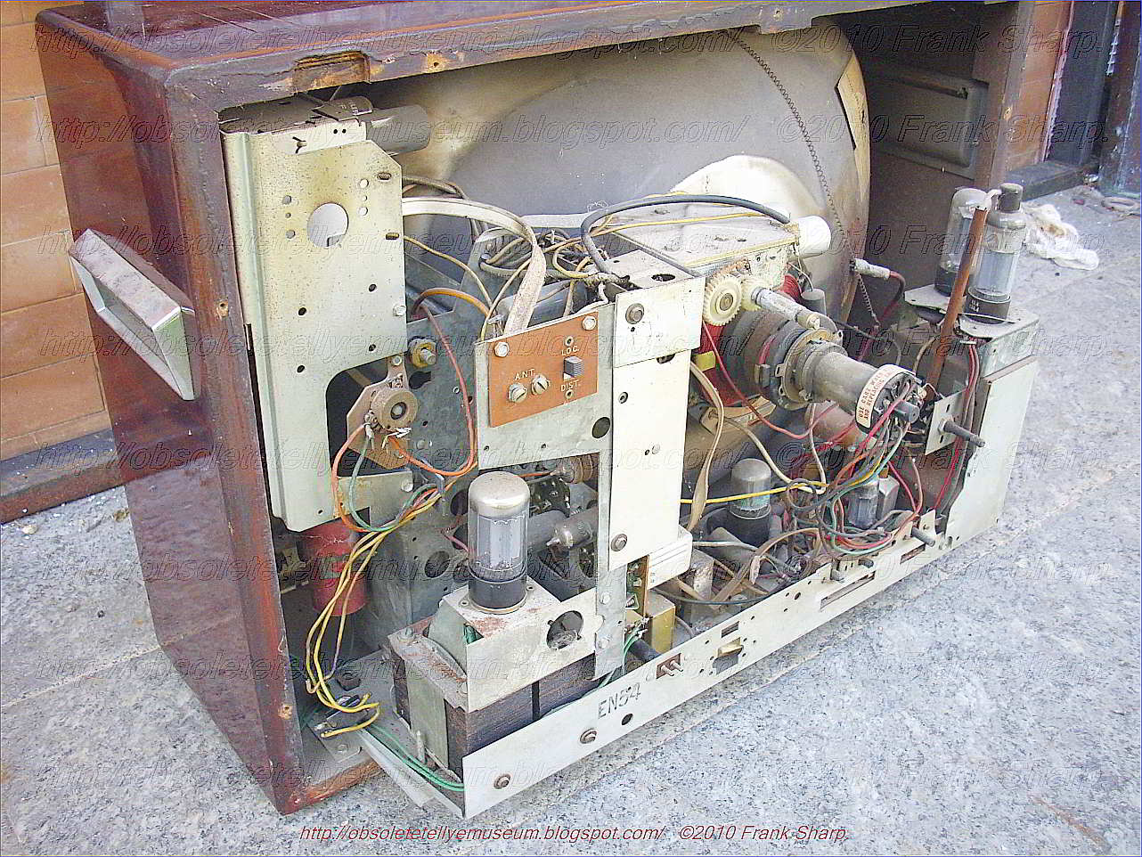
The DUMONT TELESET MODEL ?? is a heavy portable 19 inches B/W Round screen television with VHF channel drum selector and a further added UHF channel selector on rear side.
Tuning is obtained with rotatable drum selectors for VHF and variable rotatable capacitor for UHF.
A rotatable drum containing twelve pre-defined channel-specific filters determines the received channel, where the inductors of the input matching, the channel filter and the LO tank circuit are changed. The tuner is divided into two chambers for maximum isolation between the sensitive RF input and the mixer-oscillator-IF section with its much larger signals. Also on the drum there are eventually two separate sub-modules.
It's completely based on tubes technology.
With this concept, which essentially turned the tuner module into a kind of Lego building block construction, many different tuners became possible. Depending upon the country of destination and its associated standard and IF settings, the required filter modules would be selected. Service workshops and tv fabricants could later even add or exchange modules when new channels were introduced, since every inductor module had its individual factory code and could be ordered separately. As a consequence more versions of the tuner were produced, covering at least standards B, B-for-Italy, C. E, F and M.

The principle of the drum tuner. On an axis two times 12 regularly spaced channel-specific filter modules are mounted. In front are twelve channel filter modules for both the channel filter and LO tank circuit tuning. Seven contacts are available, and one module is shown removed. The second row contains 12 modules with five contacts for the input filter circuit. In the tuner module the front section (for mixer-ocillator and channel filter) is separated by a metal shield from the rear RF input and pre-amp section. [Philips Service "Documentatie voor de kanalenkiezers met spoelenwals", 1954]
 Examples
of the filter modules as used in the drum tuner. Left the 5-contact
input filter, right the 7-contact BPF and LO tank filters. In both
modules the coils are co-axial for (maximum) mutual coupling.
Examples
of the filter modules as used in the drum tuner. Left the 5-contact
input filter, right the 7-contact BPF and LO tank filters. In both
modules the coils are co-axial for (maximum) mutual coupling.
The second new valve introduced in the tuners family was the PCF80, a triode-pentode combo valve specifically designed for the VHF mixer-oscillator role. First order the circuit principles didn't change too much from the previous ECC81 based generation, with the triode acting as a Colpitts oscillator with a tuned feedback from anode to grid. The oscillator voltage was minimally 5V at the grid, and would be inductively coupled to the input of the mixer pentode. This inductive coupling was achieved by putting the oscillator coil S7 and the BPF coils S5 and S6 on the same rod inside the drum tuner filter modules, see Fig.5 above. By adjusting the distance between these coils for each channel filter module, the coupling constant could be kept more or less constant across all channels, providing as much as possible a frequency-independent mixer performance. For the mixer the pentode replaced the previous triode, providing more feedback isolation between anode and grid. All in all the new tuner must have given a considerable performance improvement compared to the previous generation.
Television receivers currently being manufactured for consumer use were capable of operation in either the VHF (very high frequency) or UHF (ultra high frequency) bands of frequencies. In order to provide this capability, however, it is necessary to include two separate tuners or tuning circuits in the television receiver with one of these circuits being utilized for VHF reception and the other being used for UHF reception. The VHF tuner conventionally is a turret type of tuner having 13 detented positions which accomplish the coarse tuning or channel selection of the VHF tuner and a separate control is provided to effect the fine tuning at each of the channel positions. Generally, mechanical channel selecting devices for VHF television tuners fall into two groups, namely, the rotary-switching type or the turret types. Turret type tuners include an incrementally rotatable channel selector shaft for selectively connecting certain ones of a plurality of tuned circuit elements to each of a plurality of channel selector positions. UHF tuners generally employ a separate control mechanism or a tuning knob and use a dial indicator of a type commonly found in manual radio receivers. UHF tuners for television receivers are usually of a continuous tuning type similar to the tuning system adapted for radio sets. Therefore, the tuning in UHF channels has been extremely difficult as compared to the tuning in VHF channels. Such continuous tuning systems for the UHF tuners has heretofore been sufficient, since only two or three UHF channels have been authorized in one locality. However, where more UHF channels, namely seven or eight channels, are available for reception, a non-continuous type UHF tuner, which enables simpler tuning operation, is desired. Nevertheless, this continuous tuning system has heretofore been satisfactory, because there were only 2 or 3 UHF band channels or stations available for reception in an area. However, where there are an increased number (7 or 8 or more, for instance) of UHF band channels or stations available for reception, a non-continuous or intermittent tuning system as is adopted for the VHF tuner is preferable.
More desirably, the fine tuning control is presettable, so that the desired channel may be readily selected by merely turning the main channel switch-over shaft. The use of two separate tuning control mechanisms in order to effect the VHF and UHF tuning of the receiver is at best; and when a receiver is provided with remote control capabilities, generally only the VHF band of frequencies may be remote controlled and the UHF channels still must be selected manually at the receiving set location.Conventional turret tuners still leave room for improvement, especially as far as minimizing the tuner size and dimension, and simplifying the assembly, as well as lowering the manufacture costs and improving the tuner performance are concerned.
The rear cover lid is a full steel panel directly grounded chassis mains live !!!!
A voltage changer is present but the set is originally powered at 125volt.
Completely based on tubes technology even in power supply.
The set is last DUMONT set fabricated before closing activity in 1960.

The B/W Tubes Television set was powered with a External Voltage stabiliser unit for Television (portable metal box) which relates to voltage regulators of the type employed to supply alternating current and a constant voltage to a load circuit from a source in which the line voltage varies. Conventional AC-operated television receivers exhibit several undesirable performance attributes. For example, under low-line voltage conditions such as those encountered during peak load periods or temporary power brown-outs imposed during times of power shortage, picture shrinkage and defocusing are encountered and under extreme brown-out conditions the receiver loses synchronization with a resultant total loss of picture intelligibility.
On the other hand, abnormally high-line voltage conditions are sometimes encountered, and this can lead to excessive high voltage and X-ray generation. In addition, either abnormally high steady state line voltage conditions or high voltage transients such as those encountered during electrical storms or during power line switching operations may subject the active devices and other components of the receiver to over-voltage stresses which can lead to excessive component failure.
It is a principal object of the present invention to provide a new and improved AC-operated television receiver having greatly improved performance characteristics in the presence of fluctuating power supply voltages.
A more specific object of the invention is to provide an AC-operated television receiver affording substantially undegraded performance under even extremely low-line voltage conditions without excessive high voltage and X-ray generation under even extremely high-line voltage conditions.
Still another and extremely important object of the invention is to provide a new and improved AC-operated television receiver having greatly improved reliability against component failure. Such regulators are frequently provided employing saturable core reactors and condensers connected in circuit... in such manner as to provide a plurality of variable voltage vectors which vary in different senses, as the line voltage varies, but which add vectorially in such manner that their vector sum remains substantially constant upon variations in line voltage, for providing automatic voltage stabilization of single or multiphase A. C. circuits where the supply voltage and frequency are subject to variation above and below normal value and where the load is subject to variation between normal limits.
voltage stabilization is automatically effected by the provision of an inductive pilot control device which is adapted to provide two excitation supply voltages for producing excitation or satuation of two magnetic circuits of a reversible booster transformer unit or units and diversion of flux from one magnetic circuit to the other, the booster unit being energized by primary windings from the A. C. supplysystem and being provided with a secondary winding or windings connected between the supply system and the corresponding inain or distribution circuit and in series therewith, through which a corrective boost voltage is
introduced into the circuit under the influence of the pilot control device, of an amount equal to that of the supply voltage fluctuation which initiated it and appropriate in polarity and direction for restoring the voltage to normal value and providing automatic stabilization of the circuit voltage against supply voltages which fluctuate above and below normal value.
 The pilot control device which may be employed singly or may
comprise three units or their equivalent when applied to multiphase
supply systems comprises a pair of closed magnetic circuits or cores
constructed of strip wound magnetic material or stacked laminations, the
two
The pilot control device which may be employed singly or may
comprise three units or their equivalent when applied to multiphase
supply systems comprises a pair of closed magnetic circuits or cores
constructed of strip wound magnetic material or stacked laminations, the
two
circuits forming a pair being constructed of materials possessing dis~similar magnetic characteristics when jointly energized by identical windings in series or by a collective primary winding, the said magnetic circuits being suitably proportioned to provide equal fluxes when ener-
gized at normal voltage.
The pilot control device is provided with a main and an auxiliary secondary winding or group of windings, the main secondary winding or windings being adapted to provide a voltage representing the difference in the fluxes of the two circuits to which it is jointly associated, while
the auxiliary secondary winding embraces only one circuit, preferably that subject to the least amount of flux variation. Either of the windings consists of two equal sections or in effect a double winding with a center tapping to which one end of the single winding is connected.
The voltage in the single secondary winding of the pilot device bec omes
directionally additive to that in one half of the tapped secondary
winding and substractive in respect to that in the other half. When the
supply voltage is normal the voltage provided by the single secondary
winding is zero, since there is no difference of flux in the two magnetic
circuits, and the two excitation voltages
omes
directionally additive to that in one half of the tapped secondary
winding and substractive in respect to that in the other half. When the
supply voltage is normal the voltage provided by the single secondary
winding is zero, since there is no difference of flux in the two magnetic
circuits, and the two excitation voltages
produced in the halves of the other secondary winding are equal and when connected to the two excitation windings of the booster units, do not produce any diversion of flux between the two circuits or sets of circuits in the magnetic system of the booster transformer unit become equal, and since the series winding on the booster unit is arranged to provide a voltage due to the difference of
the fluxes in its two magnetic circuits or sets of magnetic circuits, no corrective voltage is introduced into the main circuit by the booster. If, however, the supply voltage varies from normal the pilot control device provides a voltage across the one secondary winding due to the difference in the fluxes of the two dis-similar magnetic circuits of which it is comprised, which voltage is combined with thosc in the halves of the other secondary winding to provide two excitation voltages which vary complementarily to each other as the supply voltage fluotuates, and cause a transference of flux between the two
circuits or groups of circuits in the booster unit and automatically provide a corrective boost voltage in the main circuit in which the series winding of the booster transformer is includcd of a value equal to that of the variation in supply voltage which initiated it.
The pilot device may be arranged in various ways, forboth single phase and multiphase operation, as exemplified by the constructions hereinafter more fully described.Similarly, numerous arrangements of the booster transformer unit are possible, some of which are hereinafter described in detail. The booster transformer unit embodies thc principles of the inductive devices described in my co-pending Application No. 411,189, filed February 18, 1954.
As an alternative to the provision of an auxiliary secondary winding on the pilot control device this may be
replaced by an independent or external source of supply,which may be either subject to or independent of supply voltage variation, provided such supply may be arranged with a center tapping if required.
Feed-back arrangements may be employed for providing compensation against voltage drop due to the effects of load in various ways. These are preferably providedon the booster transformer unit and may comprise a current transformer in one or more lines of the main circuit,
the secondary output of the transformer being rectified and arranged to energize an additional excitation winding on the booster transformer unit which in clfect increases the amount of the corrective boost voltage as the load increases.
History:DuMont Labs, Allen B., Inc. (USA)
Founded: 1931
Closed: 1960
Radioproduction: 1938 - 1958
Allen B. DuMont supervised electron tube production for Westinghouse starting in 1924. In 1931 he founded his own company in Montclair, NJ. In 1932 he invented the "Magic Eye" cathode ray tube, and sold the rights to RCA. In 1933 he invented an early form of radar, which he was asked to keep secret (not patent) by the U.S. military. In 1934, DuMont Labs moved to Passaic, NJ. DuMont sold the first all-electronic TV (Model 180) in the U.S. in 1938. DuMont was an influential member of the National Television Standards Committee (NTSC). In 1946, the DuMont TV Network was established, with stations WABD (New York) and WTTG (Washington D.C.). The DuMont Network eventually grew to 200 stations and was sold to Metromedia in 1956. DuMont Labs produced high quality (and expensive) TVs until 1958, when the consumer products business was sold to Emerson. Notable models include the "Royal Sovereign" with its 30-inch CRT. DuMont's cathode ray tube division was sold to Fairchild Camera and Instrument in 1960 to become the A. B. DuMont Division of Fairchild, which developed the Sony Trinitron CRT under contract.
Foundation of Allen B. DuMont Laboratories, Inc.
- In 1931, Allen B. DuMont founded Allen B. DuMont Laboratories, Inc., in his garage with $1000-half of it borrowed. The company achieved its initial success as the primary U.S. manufacturer of cathode-ray tubes, which had become critical to the electronics industry. DuMont entered into television broadcasting---first experimentally, then as a commercial venture-in 1938. In fact, the only way to receive NBC-RCA's historic public broadcast of television outside their 1939 World's Fair pavilion was on sets made by DuMont Labs.
DuMont first became involved in broadcasting by building a radio transmitter and transmitter and receiver out of an oatmeal box while suffering from polio. In 1924, he received an electrical engeneering degree from Rensselaer Polytechnical Institute. After graduation, he joined the Westinghouse Lamp Company as an engineer at a time when 500 tubes a day were being produced. Later DuMont became supervisor and initiated technical improvements that increased production to 5,000 tubes per hour. In 1928, he worked closely with Dr. Lee DeForest on expanding radio, but left later to explore television.
DuMont achieved a number of firsts in commercial television practice, but with little success. He tried to expand his network too rapidly both in the number of affiliates and the number of hours of programming available to affiliates each week. Even as DuMont was developing into the first commercial television network, the other networks, most notably CBS and NBC, were preparing for the time when rapid network expansion was most feasible-experimenting with various program formats and talent borrowed from their radio networks, as well as encouraging their most prestigious and financially successful radio affiliates to apply for television licenses.
Prime-time programming was a major problem for DuMont. The network would not or could not pay for expensive shows that would deliver large audiences, thereby attracting powerful sponsors. When a quality show drew a large audience in spite of its budget, it was snatched by CBS or NBC. DuMont televised the occasional successful show, including Cavalcade of Stars (before Jackie Gleason left), Captain Video, and Bishop Fulton J. Sheen's Life Is Worth Living. The network never seemed to generate enough popular programming to keep it afloat, however-possibly be- cause it lacked the backing of a radio network.
The NBC, CBS and ABC radio networks provided financial support for their television ventures while the fledgling industry was growing-creating what the FCC deemed 'an ironic situation in which one communications medium financed the development of its competitor." DuMont's only outside financial assistance came from Paramount Studios between 1938 and 1941. The company created and sold class-B common stock exclusively to Paramount for one dollar per share and a promise to provide affiliation with CBS and NBC. Analysts have suggested that DuMont's lack of primary affiliates was a key factor in the network's demise.
One important factor contributing to the demise of the DuMont Network was Allen B. DuMont himself. Many people thought of him as a "bypassed pioneer" with no head for business. Major stockholders began to publicly question the soundness of his decisions, especially his desire to keep the TV network afloat despite major losses. In 1955, concerned holders of large blocks of DuMont stock began to wrest control from the company founder.
When the fiscally weakened DuMont corporation spun off its television broadcasting facilities in 1955, Business Week claimed that DuMont had been forced into television programming in order to provide a market for his TV receivers. No evidence has been found to support this claim, however. In markets where licenses for television stations were being granted during the postwar period, there were sufficient license applicants to provide audiences with programming to stimulate set sales. One reason DuMont television sales lagged behind other manufactures was that his sets were of higher quality, and consequently much more expensive. In fact, in 1951 DuMont cut back television set production by 60%-although profits from this division had been subsidizing the TV network-because other manufactures were undercutting DuMont's prices.
After the DuMont Television Network and its owned- and-operated stations were spun off into a new corporation, there remained only two major divisions of Allen B. DuMont Laboratories, Inc. In 1958 Emerson Electric Company purchased the DuMont consumer products manufacturing division. DuMont was no longer employed by his own company when the last division-oscillograph and cathode-ray tube manufacturing--was sold to Fairchild in 1960. DuMont was hired by Fairchild as group general manager of the A. B. DuMont Division of Fairchild Camera and Instrument Corporation until his death in 1965.
DuMont may have remained in television broadcasting despite fiscal losses in order to uphold the title once given him, 'the father of commercial television."
His company pioneered many important elements necessary to the growth and evolution of the industry. DuMont engineers perfected the use of cathode-ray tubes as TV screens, developed the kinescope process, as well as the "magic eye cathode-ray radio tuning indicator, and the first electronic viewfinder. DuMont was an intelligent and energetic engineer who took risks and profited financially from them-becoming history's first television millionaire. But when the big radio networks entered the field of television, DuMont was unable to compete with these financially powerful, considerably experienced broadcaster.
Allen B(alcom) DuMont Born in Brooklyn, New York, U.S.A., 29 January 1901. Educated at Rensselaer Polytechnic Institute, Troy, New York, B.S. in electrical engineering 1924. Married: Ethel; children: Allen B.,Jr., and Yvonne. Began career with the Westinghouse Lamp Company; conducted TV experiments in his garage,
1920s; developed an inexpensive cathode- ray tube that would last for thousands of hours (unlike the popular German import CRT, which lasted only 25 to 30 hours), DeForest Radio Company,
1930; left to found his laboratory,
1931; incorporated DuMont Labs,
1935; sold a half-interest to Paramount Pictures Corporation to raise capital for broadcasting stations, 1938; DuMont Labs was first company to market home television receiver,
1939; granted experimental TV licenses in Passaic, New Jersey, and New York,
1942; DuMont TV Network separated from DuMont Labs, sold to the Metropolitan Broadcasting Company; Emerson Radio and Phonograph Corp. purchased DuMont's television, phonograph, and stereo producing division; remaining DuMont interests merged with the Fairchild Camera and Instrument Corp.,
1960; named group general manager of DuMont divisions of Fairchild,
1960; named senior technical consultant,
1961. Honorary doctorates: Rensselaer and Brooklyn Polytechnic Institutes. Recipient: Marconi Memorial Medal for Achievement,
1945; American Television Society,
1943; several trophies for accuracy in navigation and calculations in power-boat racing.
Died in Montclair, New Jersey, 16 November 1965.
Weinstein, David (2009). The Forgotten Network: DuMont and the Birth of American Television. Temple University Press. ISBN 9781592134991.
Adams,
Edie (March 1996). "Television/Video Preservation Study: Los Angeles
Public Hearing". National Film Preservation Board. Library of Congress.
Tuning is obtained with rotatable drum selectors for VHF and variable rotatable capacitor for UHF.
A rotatable drum containing twelve pre-defined channel-specific filters determines the received channel, where the inductors of the input matching, the channel filter and the LO tank circuit are changed. The tuner is divided into two chambers for maximum isolation between the sensitive RF input and the mixer-oscillator-IF section with its much larger signals. Also on the drum there are eventually two separate sub-modules.
It's completely based on tubes technology.
With this concept, which essentially turned the tuner module into a kind of Lego building block construction, many different tuners became possible. Depending upon the country of destination and its associated standard and IF settings, the required filter modules would be selected. Service workshops and tv fabricants could later even add or exchange modules when new channels were introduced, since every inductor module had its individual factory code and could be ordered separately. As a consequence more versions of the tuner were produced, covering at least standards B, B-for-Italy, C. E, F and M.

The principle of the drum tuner. On an axis two times 12 regularly spaced channel-specific filter modules are mounted. In front are twelve channel filter modules for both the channel filter and LO tank circuit tuning. Seven contacts are available, and one module is shown removed. The second row contains 12 modules with five contacts for the input filter circuit. In the tuner module the front section (for mixer-ocillator and channel filter) is separated by a metal shield from the rear RF input and pre-amp section. [Philips Service "Documentatie voor de kanalenkiezers met spoelenwals", 1954]

The second new valve introduced in the tuners family was the PCF80, a triode-pentode combo valve specifically designed for the VHF mixer-oscillator role. First order the circuit principles didn't change too much from the previous ECC81 based generation, with the triode acting as a Colpitts oscillator with a tuned feedback from anode to grid. The oscillator voltage was minimally 5V at the grid, and would be inductively coupled to the input of the mixer pentode. This inductive coupling was achieved by putting the oscillator coil S7 and the BPF coils S5 and S6 on the same rod inside the drum tuner filter modules, see Fig.5 above. By adjusting the distance between these coils for each channel filter module, the coupling constant could be kept more or less constant across all channels, providing as much as possible a frequency-independent mixer performance. For the mixer the pentode replaced the previous triode, providing more feedback isolation between anode and grid. All in all the new tuner must have given a considerable performance improvement compared to the previous generation.
Television receivers currently being manufactured for consumer use were capable of operation in either the VHF (very high frequency) or UHF (ultra high frequency) bands of frequencies. In order to provide this capability, however, it is necessary to include two separate tuners or tuning circuits in the television receiver with one of these circuits being utilized for VHF reception and the other being used for UHF reception. The VHF tuner conventionally is a turret type of tuner having 13 detented positions which accomplish the coarse tuning or channel selection of the VHF tuner and a separate control is provided to effect the fine tuning at each of the channel positions. Generally, mechanical channel selecting devices for VHF television tuners fall into two groups, namely, the rotary-switching type or the turret types. Turret type tuners include an incrementally rotatable channel selector shaft for selectively connecting certain ones of a plurality of tuned circuit elements to each of a plurality of channel selector positions. UHF tuners generally employ a separate control mechanism or a tuning knob and use a dial indicator of a type commonly found in manual radio receivers. UHF tuners for television receivers are usually of a continuous tuning type similar to the tuning system adapted for radio sets. Therefore, the tuning in UHF channels has been extremely difficult as compared to the tuning in VHF channels. Such continuous tuning systems for the UHF tuners has heretofore been sufficient, since only two or three UHF channels have been authorized in one locality. However, where more UHF channels, namely seven or eight channels, are available for reception, a non-continuous type UHF tuner, which enables simpler tuning operation, is desired. Nevertheless, this continuous tuning system has heretofore been satisfactory, because there were only 2 or 3 UHF band channels or stations available for reception in an area. However, where there are an increased number (7 or 8 or more, for instance) of UHF band channels or stations available for reception, a non-continuous or intermittent tuning system as is adopted for the VHF tuner is preferable.
More desirably, the fine tuning control is presettable, so that the desired channel may be readily selected by merely turning the main channel switch-over shaft. The use of two separate tuning control mechanisms in order to effect the VHF and UHF tuning of the receiver is at best; and when a receiver is provided with remote control capabilities, generally only the VHF band of frequencies may be remote controlled and the UHF channels still must be selected manually at the receiving set location.Conventional turret tuners still leave room for improvement, especially as far as minimizing the tuner size and dimension, and simplifying the assembly, as well as lowering the manufacture costs and improving the tuner performance are concerned.
The rear cover lid is a full steel panel directly grounded chassis mains live !!!!
A voltage changer is present but the set is originally powered at 125volt.
Completely based on tubes technology even in power supply.
The set is last DUMONT set fabricated before closing activity in 1960.

The B/W Tubes Television set was powered with a External Voltage stabiliser unit for Television (portable metal box) which relates to voltage regulators of the type employed to supply alternating current and a constant voltage to a load circuit from a source in which the line voltage varies. Conventional AC-operated television receivers exhibit several undesirable performance attributes. For example, under low-line voltage conditions such as those encountered during peak load periods or temporary power brown-outs imposed during times of power shortage, picture shrinkage and defocusing are encountered and under extreme brown-out conditions the receiver loses synchronization with a resultant total loss of picture intelligibility.
On the other hand, abnormally high-line voltage conditions are sometimes encountered, and this can lead to excessive high voltage and X-ray generation. In addition, either abnormally high steady state line voltage conditions or high voltage transients such as those encountered during electrical storms or during power line switching operations may subject the active devices and other components of the receiver to over-voltage stresses which can lead to excessive component failure.
It is a principal object of the present invention to provide a new and improved AC-operated television receiver having greatly improved performance characteristics in the presence of fluctuating power supply voltages.
A more specific object of the invention is to provide an AC-operated television receiver affording substantially undegraded performance under even extremely low-line voltage conditions without excessive high voltage and X-ray generation under even extremely high-line voltage conditions.
Still another and extremely important object of the invention is to provide a new and improved AC-operated television receiver having greatly improved reliability against component failure. Such regulators are frequently provided employing saturable core reactors and condensers connected in circuit... in such manner as to provide a plurality of variable voltage vectors which vary in different senses, as the line voltage varies, but which add vectorially in such manner that their vector sum remains substantially constant upon variations in line voltage, for providing automatic voltage stabilization of single or multiphase A. C. circuits where the supply voltage and frequency are subject to variation above and below normal value and where the load is subject to variation between normal limits.
voltage stabilization is automatically effected by the provision of an inductive pilot control device which is adapted to provide two excitation supply voltages for producing excitation or satuation of two magnetic circuits of a reversible booster transformer unit or units and diversion of flux from one magnetic circuit to the other, the booster unit being energized by primary windings from the A. C. supplysystem and being provided with a secondary winding or windings connected between the supply system and the corresponding inain or distribution circuit and in series therewith, through which a corrective boost voltage is
introduced into the circuit under the influence of the pilot control device, of an amount equal to that of the supply voltage fluctuation which initiated it and appropriate in polarity and direction for restoring the voltage to normal value and providing automatic stabilization of the circuit voltage against supply voltages which fluctuate above and below normal value.

circuits forming a pair being constructed of materials possessing dis~similar magnetic characteristics when jointly energized by identical windings in series or by a collective primary winding, the said magnetic circuits being suitably proportioned to provide equal fluxes when ener-
gized at normal voltage.
The pilot control device is provided with a main and an auxiliary secondary winding or group of windings, the main secondary winding or windings being adapted to provide a voltage representing the difference in the fluxes of the two circuits to which it is jointly associated, while
the auxiliary secondary winding embraces only one circuit, preferably that subject to the least amount of flux variation. Either of the windings consists of two equal sections or in effect a double winding with a center tapping to which one end of the single winding is connected.
The voltage in the single secondary winding of the pilot device bec
 omes
directionally additive to that in one half of the tapped secondary
winding and substractive in respect to that in the other half. When the
supply voltage is normal the voltage provided by the single secondary
winding is zero, since there is no difference of flux in the two magnetic
circuits, and the two excitation voltages
omes
directionally additive to that in one half of the tapped secondary
winding and substractive in respect to that in the other half. When the
supply voltage is normal the voltage provided by the single secondary
winding is zero, since there is no difference of flux in the two magnetic
circuits, and the two excitation voltagesproduced in the halves of the other secondary winding are equal and when connected to the two excitation windings of the booster units, do not produce any diversion of flux between the two circuits or sets of circuits in the magnetic system of the booster transformer unit become equal, and since the series winding on the booster unit is arranged to provide a voltage due to the difference of
the fluxes in its two magnetic circuits or sets of magnetic circuits, no corrective voltage is introduced into the main circuit by the booster. If, however, the supply voltage varies from normal the pilot control device provides a voltage across the one secondary winding due to the difference in the fluxes of the two dis-similar magnetic circuits of which it is comprised, which voltage is combined with thosc in the halves of the other secondary winding to provide two excitation voltages which vary complementarily to each other as the supply voltage fluotuates, and cause a transference of flux between the two
circuits or groups of circuits in the booster unit and automatically provide a corrective boost voltage in the main circuit in which the series winding of the booster transformer is includcd of a value equal to that of the variation in supply voltage which initiated it.
The pilot device may be arranged in various ways, forboth single phase and multiphase operation, as exemplified by the constructions hereinafter more fully described.Similarly, numerous arrangements of the booster transformer unit are possible, some of which are hereinafter described in detail. The booster transformer unit embodies thc principles of the inductive devices described in my co-pending Application No. 411,189, filed February 18, 1954.
As an alternative to the provision of an auxiliary secondary winding on the pilot control device this may be
replaced by an independent or external source of supply,which may be either subject to or independent of supply voltage variation, provided such supply may be arranged with a center tapping if required.
Feed-back arrangements may be employed for providing compensation against voltage drop due to the effects of load in various ways. These are preferably providedon the booster transformer unit and may comprise a current transformer in one or more lines of the main circuit,
the secondary output of the transformer being rectified and arranged to energize an additional excitation winding on the booster transformer unit which in clfect increases the amount of the corrective boost voltage as the load increases.
History:DuMont Labs, Allen B., Inc. (USA)
Founded: 1931
Closed: 1960
Radioproduction: 1938 - 1958
Allen B. DuMont supervised electron tube production for Westinghouse starting in 1924. In 1931 he founded his own company in Montclair, NJ. In 1932 he invented the "Magic Eye" cathode ray tube, and sold the rights to RCA. In 1933 he invented an early form of radar, which he was asked to keep secret (not patent) by the U.S. military. In 1934, DuMont Labs moved to Passaic, NJ. DuMont sold the first all-electronic TV (Model 180) in the U.S. in 1938. DuMont was an influential member of the National Television Standards Committee (NTSC). In 1946, the DuMont TV Network was established, with stations WABD (New York) and WTTG (Washington D.C.). The DuMont Network eventually grew to 200 stations and was sold to Metromedia in 1956. DuMont Labs produced high quality (and expensive) TVs until 1958, when the consumer products business was sold to Emerson. Notable models include the "Royal Sovereign" with its 30-inch CRT. DuMont's cathode ray tube division was sold to Fairchild Camera and Instrument in 1960 to become the A. B. DuMont Division of Fairchild, which developed the Sony Trinitron CRT under contract.
Foundation of Allen B. DuMont Laboratories, Inc.
- In 1931, Allen B. DuMont founded Allen B. DuMont Laboratories, Inc., in his garage with $1000-half of it borrowed. The company achieved its initial success as the primary U.S. manufacturer of cathode-ray tubes, which had become critical to the electronics industry. DuMont entered into television broadcasting---first experimentally, then as a commercial venture-in 1938. In fact, the only way to receive NBC-RCA's historic public broadcast of television outside their 1939 World's Fair pavilion was on sets made by DuMont Labs.
DuMont first became involved in broadcasting by building a radio transmitter and transmitter and receiver out of an oatmeal box while suffering from polio. In 1924, he received an electrical engeneering degree from Rensselaer Polytechnical Institute. After graduation, he joined the Westinghouse Lamp Company as an engineer at a time when 500 tubes a day were being produced. Later DuMont became supervisor and initiated technical improvements that increased production to 5,000 tubes per hour. In 1928, he worked closely with Dr. Lee DeForest on expanding radio, but left later to explore television.
DuMont achieved a number of firsts in commercial television practice, but with little success. He tried to expand his network too rapidly both in the number of affiliates and the number of hours of programming available to affiliates each week. Even as DuMont was developing into the first commercial television network, the other networks, most notably CBS and NBC, were preparing for the time when rapid network expansion was most feasible-experimenting with various program formats and talent borrowed from their radio networks, as well as encouraging their most prestigious and financially successful radio affiliates to apply for television licenses.
Prime-time programming was a major problem for DuMont. The network would not or could not pay for expensive shows that would deliver large audiences, thereby attracting powerful sponsors. When a quality show drew a large audience in spite of its budget, it was snatched by CBS or NBC. DuMont televised the occasional successful show, including Cavalcade of Stars (before Jackie Gleason left), Captain Video, and Bishop Fulton J. Sheen's Life Is Worth Living. The network never seemed to generate enough popular programming to keep it afloat, however-possibly be- cause it lacked the backing of a radio network.
The NBC, CBS and ABC radio networks provided financial support for their television ventures while the fledgling industry was growing-creating what the FCC deemed 'an ironic situation in which one communications medium financed the development of its competitor." DuMont's only outside financial assistance came from Paramount Studios between 1938 and 1941. The company created and sold class-B common stock exclusively to Paramount for one dollar per share and a promise to provide affiliation with CBS and NBC. Analysts have suggested that DuMont's lack of primary affiliates was a key factor in the network's demise.
One important factor contributing to the demise of the DuMont Network was Allen B. DuMont himself. Many people thought of him as a "bypassed pioneer" with no head for business. Major stockholders began to publicly question the soundness of his decisions, especially his desire to keep the TV network afloat despite major losses. In 1955, concerned holders of large blocks of DuMont stock began to wrest control from the company founder.
When the fiscally weakened DuMont corporation spun off its television broadcasting facilities in 1955, Business Week claimed that DuMont had been forced into television programming in order to provide a market for his TV receivers. No evidence has been found to support this claim, however. In markets where licenses for television stations were being granted during the postwar period, there were sufficient license applicants to provide audiences with programming to stimulate set sales. One reason DuMont television sales lagged behind other manufactures was that his sets were of higher quality, and consequently much more expensive. In fact, in 1951 DuMont cut back television set production by 60%-although profits from this division had been subsidizing the TV network-because other manufactures were undercutting DuMont's prices.
After the DuMont Television Network and its owned- and-operated stations were spun off into a new corporation, there remained only two major divisions of Allen B. DuMont Laboratories, Inc. In 1958 Emerson Electric Company purchased the DuMont consumer products manufacturing division. DuMont was no longer employed by his own company when the last division-oscillograph and cathode-ray tube manufacturing--was sold to Fairchild in 1960. DuMont was hired by Fairchild as group general manager of the A. B. DuMont Division of Fairchild Camera and Instrument Corporation until his death in 1965.
DuMont may have remained in television broadcasting despite fiscal losses in order to uphold the title once given him, 'the father of commercial television."
His company pioneered many important elements necessary to the growth and evolution of the industry. DuMont engineers perfected the use of cathode-ray tubes as TV screens, developed the kinescope process, as well as the "magic eye cathode-ray radio tuning indicator, and the first electronic viewfinder. DuMont was an intelligent and energetic engineer who took risks and profited financially from them-becoming history's first television millionaire. But when the big radio networks entered the field of television, DuMont was unable to compete with these financially powerful, considerably experienced broadcaster.
Allen B(alcom) DuMont Born in Brooklyn, New York, U.S.A., 29 January 1901. Educated at Rensselaer Polytechnic Institute, Troy, New York, B.S. in electrical engineering 1924. Married: Ethel; children: Allen B.,Jr., and Yvonne. Began career with the Westinghouse Lamp Company; conducted TV experiments in his garage,
1920s; developed an inexpensive cathode- ray tube that would last for thousands of hours (unlike the popular German import CRT, which lasted only 25 to 30 hours), DeForest Radio Company,
1930; left to found his laboratory,
1931; incorporated DuMont Labs,
1935; sold a half-interest to Paramount Pictures Corporation to raise capital for broadcasting stations, 1938; DuMont Labs was first company to market home television receiver,
1939; granted experimental TV licenses in Passaic, New Jersey, and New York,
1942; DuMont TV Network separated from DuMont Labs, sold to the Metropolitan Broadcasting Company; Emerson Radio and Phonograph Corp. purchased DuMont's television, phonograph, and stereo producing division; remaining DuMont interests merged with the Fairchild Camera and Instrument Corp.,
1960; named group general manager of DuMont divisions of Fairchild,
1960; named senior technical consultant,
1961. Honorary doctorates: Rensselaer and Brooklyn Polytechnic Institutes. Recipient: Marconi Memorial Medal for Achievement,
1945; American Television Society,
1943; several trophies for accuracy in navigation and calculations in power-boat racing.
Died in Montclair, New Jersey, 16 November 1965.
See also
References
External links
- Dumont Experimental Color CRTs at the Early Television Museum
- DuMont television receiver photo at Greater Boston, June 2005 gallery of broadcasting equipment. Also available is Description and index of entire gallery.


