Richtige Fernseher haben Röhren!

Richtige Fernseher haben Röhren!

In Brief: On this site you will find pictures and information about some of the electronic, electrical and electrotechnical Obsolete technology relics that the Frank Sharp Private museum has accumulated over the years .
Premise: There are lots of vintage electrical and electronic items that have not survived well or even completely disappeared and forgotten.

Or are not being collected nowadays in proportion to their significance or prevalence in their heyday, this is bad and the main part of the death land. The heavy, ugly sarcophagus; models with few endearing qualities, devices that have some over-riding disadvantage to ownership such as heavy weight,toxicity or inflated value when dismantled, tend to be under-represented by all but the most comprehensive collections and museums. They get relegated to the bottom of the wants list, derided as 'more trouble than they are worth', or just forgotten entirely. As a result, I started to notice gaps in the current representation of the history of electronic and electrical technology to the interested member of the public.

Following this idea around a bit, convinced me that a collection of the peculiar alone could not hope to survive on its own merits, but a museum that gave equal display space to the popular and the unpopular, would bring things to the attention of the average person that he has previously passed by or been shielded from. It's a matter of culture. From this, the Obsolete Technology Tellye Web Museum concept developed and all my other things too. It's an open platform for all electrical Electronic TV technology to have its few, but NOT last, moments of fame in a working, hand-on environment. We'll never own Colossus or Faraday's first transformer, but I can show things that you can't see at the Science Museum, and let you play with things that the Smithsonian can't allow people to touch, because my remit is different.

There was a society once that was the polar opposite of our disposable, junk society. A whole nation was built on the idea of placing quality before quantity in all things. The goal was not “more and newer,” but “better and higher" .This attitude was reflected not only in the manufacturing of material goods, but also in the realms of art and architecture, as well as in the social fabric of everyday life. The goal was for each new cohort of children to stand on a higher level than the preceding cohort: they were to be healthier, stronger, more intelligent, and more vibrant in every way.

The society that prioritized human, social and material quality is a Winner. Truly, it is the high point of all Western civilization. Consequently, its defeat meant the defeat of civilization itself.

Today, the West is headed for the abyss. For the ultimate fate of our disposable society is for that society itself to be disposed of. And this will happen sooner, rather than later.

OLD, but ORIGINAL, Well made, Funny, Not remotely controlled............. and not Made in CHINA.

How to use the site:
- If you landed here via any Search Engine, you will get what you searched for and you can search more using the search this blog feature provided by Google. You can visit more posts scrolling the left blog archive of all posts of the month/year,
or you can click on the main photo-page to start from the main page. Doing so it starts from the most recent post to the older post simple clicking on the Older Post button on the bottom of each page after reading , post after post.

You can even visit all posts, time to time, when reaching the bottom end of each page and click on the Older Post button.

- If you arrived here at the main page via bookmark you can visit all the site scrolling the left blog archive of all posts of the month/year pointing were you want , or more simple You can even visit all blog posts, from newer to older, clicking at the end of each bottom page on the Older Post button.
So you can see all the blog/site content surfing all pages in it.

- The search this blog feature provided by Google is a real search engine. If you're pointing particular things it will search IT for you; or you can place a brand name in the search query at your choice and visit all results page by page. It's useful since the content of the site is very large.

Note that if you don't find what you searched for, try it after a period of time; the site is a never ending job !

Every CRT Television saved let revive knowledge, thoughts, moments of the past life which will never return again.........

Many contemporary "televisions" (more correctly named as displays) would not have this level of staying power, many would ware out or require major services within just five years or less and of course, there is that perennial bug bear of planned obsolescence where components are deliberately designed to fail and, or manufactured with limited edition specificities..... and without considering........picture......sound........quality........
..............The bitterness of poor quality is remembered long after the sweetness of todays funny gadgets low price has faded from memory........ . . . . . .....
Don't forget the past, the end of the world is upon us! Pretty soon it will all turn to dust!

Have big FUN ! !
-----------------------
©2010, 2011, 2012, 2013, 2014 Frank Sharp - You do not have permission to copy photos and words from this blog, and any content may be never used it for auctions or commercial purposes, however feel free to post anything you see here with a courtesy link back, btw a link to the original post here , is mandatory.
All sets and apparates appearing here are property of Engineer Frank Sharp. NOTHING HERE IS FOR SALE !
All posts are presented here for informative, historical and educative purposes as applicable within Fair Use.


Showing posts with label 1969. Show all posts

Friday, March 18, 2022

HITACHI IA-51 YEAR 1969.


 The HITACHI  IA-51 is a portable 8 inches (23cm) portable B/W television set with rotatable VHF and UHF Channels transistorized tuners.

  • It features 2 antennas for both VHF and UHF Stations.
  • Above the cabinet the big numerical knob performs VHF tuning, frontly UHF tuner is present, volume plus ON /OFF switch.
  • Backside the usual commands for bright and kontrast vertical height and hold.
  • Also the power connector  is a special type, see above.
The set doesn't weight much. (5.4 kg / 11 lb 14.3 oz (11.894 lb))


  • Television Receiver (TV) VHF incl. FM and/or UHF with fully transistorized chassis and no ICs.
  •  Power type and voltage  Line / Batteries (any type) / 220; 12 Volt
     Loudspeaker  Permanent Magnet Dynamic  Loudspeaker (moving coil)
  •  Material build Plastics (no bakelite or catalin)

     Model: IA-51 - Hitachi Ltd.; Tokyo   Tablemodel, with any shape black and antennas.
  •  Dimensions (WHD): 325 x 225 x 237 mm / 12.8 x 8.9 x 9.3 inch
  •   23 cm Bildröhre, für Netz und 12 Volt Auto-Batteriebetrieb, Tragbares Schwarz/Weiß-Fernsehgerät.


Hitachi, Ltd. ( Kabushiki-gaisha Hitachi Seisakusho) specializing in high-technology and services headquartered in Marunouchi 1-chome, is a Japanese multinational corporationChiyoda, Tokyo, Japan. The company is the parent of the Hitachi Group (Hitachi Gurūpu) as part of the larger DKB Group companies. Hitachi is the third largest technological company by revenue as of 2009.


Corporate Name Hitachi, Ltd.
(Kabushiki Kaisha Hitachi Seisakusho)
Established February 1, 1920 [Founded in 1910]
Headquarters 6-6, Marunouchi 1-chome, Chiyoda-ku, Tokyo, 100-8280 Japan
phone:+81-3-3258-1111
Management Hiroaki Nakanishi
Representative Executive Officer and President
In-house Company System
  • Power Systems Company
  • Rail Systems Company
  • Industrial & Social Infrastructure Systems Company
  • Urban Planning and Development Systems Company
  • Information & Control Systems Company
  • Information & Telecommunication Systems Company
  • Defense Systems Company
  • Battery Systems Company

HISTORY PROGRESSION:

1910-1919 1910

* Company formed.Completed five-horsepower induction motor

1911

* Completed 2-kVA transformer

1914

* Started production of AC ammeter and voltmeter

1916

* Completed 10,000-hp (7,355-kW) water turbine
* Started production of fans

1920-1929 1924

* Completed the first large-scale DC electric locomotive to be manufactured in Japan *figure2


1930-1939 1930

* Started production of pole-top transformers


1931

* Completed 10,000-A hydraulic electrolytic cell

1932

* Started production of elevators
* Completed Hitachi's first electric refrigerator *figure3

1933

* Completed 23,600-housepower Illgner set

1940-1949 1940

* Completed 5,000-line automatic private branch exchange


1943

* Completed 85,000-kW Francis water turbine and 70,000-kVA alternating current generator

1949

* Completed first U05 power excavator

1950-1959 1951

* Completed 6,500-kW Kaplan water turbine and 7,000-kVA AC generator (first umbrella-type generator made in Japan)


1952

* Completed 21,000-kW two-stage pump-turbine

1953

* Completed true low-pressure 300-m3/h air separation machine
* Completed 55,000-kW hydrogen-cooled turbine

1954

* Completed the first large-scale cold strip mill to be produced in Japan

1955

* Completed 100,000-kW Francis water turbine and 93,000-kVA alternating current generator

1956

* Completed the first DF90 diesel-electric engine to be built in Japan

1958

* Completed six-transistor miniature portable radio
* Electron microscopes awarded the grand prix at the World Exposition in Brussels *figure4

1959

* Completed electronic computers based on transistors
* Hitachi America, Ltd. established60-1969 1960

* Developed cubic-type refrigerator


1961

* Developed fully automatic washing machine
* Completed experimental nuclear reactor

1962

* Developed exothermic self-hardening mold

1963

* Completed 265,000-kW impulse reheating cross-compound turbine

1964

* Completed the first cars for the Shinkansen (Bullet Train)
* Developed seat reservation system for Japanese National Railways
* Manufactured monorail running between Haneda Airport and Hamamatsu-cho, Tokyo

1965

* Completed HITAC 5020 system
* Completed 19-inch 90° polarized color cathode ray tube using rare earth fluorescent elements

1966

* Developed LTP processing technique for silicon transistors

1967

* Developed dry-type room air conditioner

1968

* Developed hybrid LSI
* Completed HIDIC 100 electronic computer for control applications
* Developed 300-m/min elevators for high-rise buildings

1969

* Completed on-line banking system
* Developed and mass-produced all-transistor color televisions
* Developed Lo-D 2-Way speaker system

1970-1979 1970

* Developed computer-aided traffic control system for the Shinkansen (Bullet Train) *figure5


1971

* Competed large (1 Gbyte) file storage unit

1973

* Developed new-type image pickup tube

1974

* Developed numerically controlled ruling engine for aplanatic concave diffraction grating
* Commercial operation began at Japan's first 470,000-kW nuclear power station *figure6
* Successful automation of semiconductor assembly (automation of wire bonding for LSIs and transistors)

1975

* Developed high-performance heat transfer surface (Thermoexcell)
* Developed Hitachi High Crown Control Mill
* Completed large M-series computer system *figure7

1976

* Succeeded in trial of world's first optical transmission system

1977

* Developed high-speed amino acid analysis machine (type 837)
* Completed construction of Fugen advanced thermal converter reactor

1978

* Completed world's first field emission electron microscope with record-high resolution
* Experimental color camera with solid-state miniature image device developed

1979

* Completed HITAC M-series 200H


1980-1989 1980

* Completed 300-MW AC/DC converter for electricity link between Hokkaido and Honshu


1982

* Hitachi Europe Ltd. established
* Succeeded in world's first micro-level observation of magnetic field by the use of electron beam holography

1983

* Developed air conditioner with scroll compressor

1984

* Completed first improved standard BWR to be made in Japan
* Started mass production of 256-kilobit DRAMs *figure8

1985

* Completed the "JT-60" large-scale Tokamak device for break-even plasma experiments
* Developed CAD/CAE system with ultra-high resolution color display *figure9

1986

* Compared HITAC M-68X series

1987

* Practical application of predictive fuzzy control
* Completed large display using color liquid crystal projection

1988

* Developed quadrapedal robot
* Hitachi Asia Pte. Ltd. established

1989

* Developed world's fastest superconductive computer
* Developed superconductive MR imaging equipment
* Established two R&D centers in the U.S. and two laboratories in Europe

1990-1999 1990

* Released very large-scale computer with the world's fastest processing speed at that time
* Developed high-resolution TFT color liquid crystal display


1991

* Developed inverter-controlled electric locomotive with the world's largest control capacity
* Developed highly sensitive image pickup tubes

1992

* Completed core network 500-kV substation system
* Developed core technology for atomic manipulation and observation of atomic arrangement using scanning tunneling microscope

1993

* Developed Shinkansen (Bullet Train) with new maximum service speed of 270 km/h
* First in world to successfully demonstrate operation of single-electron memory at room temperature
* Developed capillary array DNA sequencer

1994

* Hitachi (China) Ltd. established
* Developed the original 32-bit RISC processor SuperH family
* Developed clean ATM
* Successful prototype of 1-Gbit DRAM

1995

* Developed Super TFT LCD module featuring ultra-wide viewing angles *figure10
* Developed 10-Gbit/s fiber optic transmission equipment
* Developed MULTI 2 encryption algorithm

1997

* Developed core technology for 4.7-Gbyte DVD-RAM
* Developed magnetocardiography technology for scanning cardiac patients
* Developed small proton accelerator for cancer treatment

1998

* Developed 320-Gbit/s optical data transmission system
* Developed refrigerator/air conditioner with PAM control

1999

* Commercialized lithium secondary battery using manganese system


2000- 2000

* Developed 52.5-Gbits/in2 perpendicular magnetic recording method
* Developed holographic electron microscope with 49.8-picometer resolution


2001

* Developed mobile web-gateway system
* Developed application processor for mobile phones

2002

* Developed world's smallest 0.3-mm square contactless IC chip *figure11
* Developed compact DNA analysis system genetic for SNP typing

2003

* Developed and commercialized compact, highly accurate, high-speed finger vein authentication system
* Successful measurement of infant brain functions using optical topography
* Dr. Hideaki Koizumi, a Hitachi Fellow, presented a lecture at the 400th Anniversary of the Foundation of the Pontifical Academy of Sciences, Vatican City

2004

* Developed world's smallest sensor-net terminal with a battery life of over one year
* Developed high-temperature lead-free solder paste

2005

* Explosives Trace Detection System received U.S. TSA certification
* Exhibited "EMIEW" two-wheel mobile robot capable of direct dialogue at the 2005 World Exposition Aichi, Japan
* Established Hitachi (China) Research & Development Corporation

2006

* Confirmation of electro-luminescence phenomena on injection of electrical current in ultra-thin silicon film
* Basic experiment on the application of Optical Topography as a brain-machine interface
* Mass production of 2.5-inch HDD using perpendicular magnetic recording technology

2007

* Prototype of world's smallest noncontact RFID powder IC chip (dimensions 0.05mm × 0.05mm)
* Prototype of the 2-Mbit non-volatile SPRAM chip using magnetization reversal by spin injection
* Developed EMIEW 2, a small and lightweight interactive robot

2008

* Developed lithium-ion battery system technology for use in high-speed diesel hybrid trains
* Developed technology for small but highly efficient electric motors that do not use rare metals


JAPAN IS STRANGE
Strange how situations change. It seems not so long ago that Japan and its industries, particularly electronics, could do no wrong. They taught us how to make cars and TV sets properly. They invested heavily and came up with a seem- ingly endless stream of desirable, innova- tive products. Both outsiders and insiders could see no end to this success story. We were told, by more than one leading Japanese electronics industrialist, that the 21st century would be the Japanese one, when Japan became predominant industri- ally and culturally. For the last couple of years the situation has been somewhat different. Japan is still the world's second largest economy, but the previous confidence has gone. The econo- my has stalled, and doesn't look like getting going again for some time. Profitability has become appalling, and the talk now is all of restructuring and job losses. Sony has announced that some 17,000 jobs will be lost worldwide, ten per cent of its workforce, while fifteen of its seventy factories are to be closed. Mighty Hitachi, whose activities span a much wider field and whose turnover is equivalent to over two per cent of Japan's gross domestic product, has launched a detailed review of its businesses. 6,500 of its 66,000 parent company employees are to be made redun- dant by March next year. On a consolidat- ed basis Hitachi is Japan's largest employ- er, with 330,000 staff. Businesses are to be dropped or reorganised. The story from Mitsubishi Electric is similar: there is to be a "sweeping restructuring of its portfolio of businesses". In the UK, the latest manifes- tation of this is the closure of Mitsubishi's VCR plant at Livingston. 14,500 jobs will go (8,400 in Japan) at Mitsubishi Electric, nearly ten per cent of the workforce. Other manufacturers who have announced poor results and restructuring recently include NEC, Matsushita, Sharp and Toshiba. It's all a long way since the time when, it seemed, all the Japanese had to do was to get the product right and produce more and more of it. Some of this was foreseeable. Markets reach saturation point; new products are not always a runaway success; if investment in new plant is excessive you end up with too much capacity; and so on. Then there is the fact that Japan is not isolated from econom- ic problems elsewhere: no economy that is heavily dependent on exports can be. But there are also more specific Japanese prob- lems. The banking system is beset by non- performing loans that Japanese bankers are reluctant to write off. The bubble economy of a few years ago, when asset values rose to unrealistic levels, collapsed. This is part of the cause of the banking system difficul- ties. Then there is the practice of cross - ownership, with firms owning substantial stakes in each other. This can work nicely when everything is doing well: when reces- sion looms, it aggravates the problems. Japan's unemployment rate hit a new high of 4.8 per cent (3.39m) in March, part- ly because of the corporate sector restructur- ing. Japanese industrialists hope to improve their profitability in the second half of the year, and will be helped by improved condi- tions in SE Asia. But it will be hard going, particularly to improve domestic market conditions. The Japanese have always had a high propensity to save. This increases when the economic climate is poor, with unemployment a threat. Right now Japanese consumers are saving rather than buying. No one seems to know how to alter their behaviour. There is also a demographic problem: the Japanese population is ageing. Japanese interest rates are negligible. So borrowing is not a problem. But conversely all those savings are bringing in little income. In the Western world interest rate changes often have a considerable impact on the economy. This economic tool is not available when interest rates are negligible. The Japanese have been advised to get their banking system sorted out, but that's not the sort of thing that can be done overnight. Right now the best opportunity for Japan seems to be to export its way out of its dif- ficulties, something that shouldn't be too difficult once worldwide expansion has resumed. But the high value of the yen is a drawback. From the economic viewpoint it's an extremely interesting situation, one in which the laws of economics have little to offer. This could be because such laws are, basically, descriptive rather than prescrip- tive. In the real world you can't always ini- tiate economic activity through monetary or fiscal means. Some commentators have gone so far as to suggest that the Japanese government should spend, spend, spend and print money to kick-start the economy. This is a dangerous course that can go badly wrong. It has already been tried by the Japanese government to a limited extent, with similarly limited success. The one thing that we do know is that economies are not stable. Change is ever present in one form or another. The prob- lem lies in trying to control it. This is all rather humbling, and certainly something of a comeuppance for the rather arrogant Japanese industrialists who had talked about the century of Japanese economic hegemony.


Some References:

"Hitachi Financial Statements" (PDF). Hitachi. "Hitachi to grant electron microscopes". The Jakarta Post. 5 August 2011. Retrieved 11 November 2012. "Corporate Profile". Retrieved 8 October 2014. Our Businesses : Hitachi Global. Hitachi.com. Retrieved on 2013-08-16. "Global 500 2014". Retrieved 2015-04-29. "Little Known Facts About Hitachi". Retrieved 8 October 2014. III, Kenneth E. Hendrickson (2014-11-25). The Encyclopedia of the Industrial Revolution in World History. Rowman & Littlefield. ISBN 9780810888883. Jr, Alfred D. Chandler; Hikino, Takashi; Nordenflycht, Andrew Von (2005). Inventing the Electronic Century. Harvard University Press. ISBN 9780674018051. "History (1910–1959) : Hitachi Global". Hitachi.com. 2010-06-29. Retrieved 2013-01-07. Fransman, Martin; Fransman, Professor of Economics and Director of the Institute for Japanese-European Technology Studies (Jets) Martin (1995). Japan's Computer and Communications Industry: The Evolution of Industrial Giants and Global Competitiveness. Oxford University Press. ISBN 9780198233336. "History (1910–1959)". Hitachi. Retrieved 11 November 2012. "History (1980–1999)". Hitachi. Archived from the original on 7 November 2012. Retrieved 11 November 2012. "WD to Buy Hitachi's Drive Business for $4.3 Billion". PC Magazine. 7 March 2011. Retrieved 11 November 2012. "Western Digital Closes Hitachi GST Acquisition, to Operate Separate Subsidiaries". Network World. 2012-03-09. Retrieved 2014-09-01. Television, Marc Chacksfield 2012-01-23T13:26:00 22Z. "Hitachi to stop making TVs in 2012". TechRadar. Retrieved 2019-01-15. Welch, Chris (2012-09-27). "Hitachi invents quartz glass storage capable of preserving data for millions of years". The Verge. Retrieved 2019-01-15. "Hitachi buys UK nuclear project from E.On and RWE". BBC News. 30 October 2012. Retrieved 30 October 2012. "Hitachi wins bid to build up to six UK nuclear plants". Reuters. 30 October 2012. Retrieved 30 October 2012. "Hitachi and Mitsubishi Heavy shares rise after merger". BBC News. 30 November 2012. Retrieved 2 December 2012. "MHI, Hitachi plan to merge thermal power units to boost overseas sales". The Japan Times. 30 November 2012. Retrieved 2 December 2012. "News Releases". Retrieved 8 October 2014. "Hitachi to invest $2.8B in IoT: launches new unit and platform". ReadWrite. 2016-05-11. Retrieved 2019-01-15. "Honda, Hitachi Automotive to form EV motor joint venture". Reuters. 2017-02-07. Retrieved 2019-01-15. GlobeNewsWire. "Hitachi INS Software and Zoomdata Partner to Develop Big Data Analytics Market in Japan." March 14, 2018. Retrieved March 16, 2018. "Bloomberg - Are you a robot?". www.bloomberg.com. Retrieved 2019-03-29. "Defense Systems Company". Stuart, Laura Anne (19 April 2013). "The Rebirth of the Magic Wand". Express Milwaukee. Archived from the original on 23 April 2013. Retrieved 6 May 2013. Trout, Christopher (28 August 2014). "The 46-year-old sex toy Hitachi won't talk about". Engadget. Archived from the original on 27 August 2014. Retrieved 30 August 2014. "Hitachi targets 2015 for glass-based data storage that lasts 100 million years". pcworld.com. 2012-09-25. Retrieved 2016-06-02. "Japan's nuclear companies look to restructuring". Nuclear Engineering International. 9 November 2016. Retrieved 15 February 2017. Patel, Sonal (1 June 2016). "GE-Hitachi Exits Nuclear Laser-Based Enrichment Venture". POWER. Retrieved 1 April 2017. Yasuhara, Akiko (31 March 2017). "Toshiba's U.S. unit bankruptcy dims Japan's nuclear ambitions". The Japan Times. Retrieved 1 April 2017. "UK unveils financial terms it offered Hitachi". World Nuclear News. 17 January 2019. Retrieved 18 January 2019. "G1TOWER : About Us : Hitachi Global". Hitachi, Ltd. Retrieved 2014-08-14. "Company Overview of Hitachi Communication Technologies America, Inc". bloomberg.com. Retrieved 2016-06-02. "Hitachi Certifications". Retrieved 8 October 2014. "Hitachi Transportation Systems website". Retrieved 8 October 2014. "Hitachi Launches Bid For Intercity Express Programme". Hitachi-Rail.com. 2008-06-30. Archived from the original on 2012-03-10. Retrieved 2013-01-07. "Hitachi agrees to buy Ansaldo STS and AnsaldoBreda". Railway Gazette. 24 February 2015. Retrieved 15 April 2017. "Hitachi completes Ansaldo deal". Railway Gazette. 2 November 2015. Retrieved 15 April 2017. "Hitachi buys shares in Ansaldo STS to raise stake to over 50 percent". Reuters. 24 March 2016. Retrieved 15 April 2017. PRWEB. "Hitachi Solutions Acquires Leading Microsoft Dynamics Solution Provider Ignify." December 14, 2015. Retrieved Jul 18, 2017. Hitachi company Overview – R&D Group Organization section Accessed 9th October 2014 Archived 2014-10-16 at the Wayback Machine Murph, Darren (2011-03-07). "Western Digital drops $4.3 billion to acquire Hitachi GST, enter staring contest with Seagate". Engadget.com. Retrieved 2013-01-07.

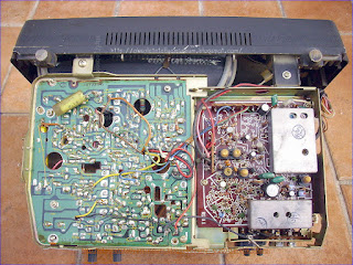
HITACHI IA-51 CHASSIS 3710683 MCI-8 INTERNAL VIEW.


The set is based around HITACHI components and chassis technology with steel frames holding all parts combining a final structured chassis. It's completely based on semiconductors.

Left above , tuners and psu, bottom 2 boards; one  for deflections and left a small signal board with VIF/SIF.

RIGHT EHT PART IN A SHIELDED BOX.

Frame output has even his Output coil/transformer.

Power Supply: The examples chosen are taken from manufacturers' circuit diagrams and are usually simplified to emphasise the fundamental nature of the circuit. For each example the particular transistor properties that are exploited to achieve the desired performance are made clear. As a rough and ready classification the circuits are arranged in order of frequency: this part is devoted to circuits used at zero frequency, field frequency and audio frequencies. Series Regulator Circuit Portable television receivers are designed to operate from batteries (usually 12V car batteries) and from the a.c. mains. The receiver usually has an 11V supply line, and circuitry is required to ensure that the supply line is at this voltage whether the power source is a battery or the mains. The supply line also needs to have good regulation, i.e. a low output resistance, to ensure that the voltage remains constant in spite of variations in the mean current taken by some of the stages in the receiver. Fig. 1 shows a typical circuit of the power -supply arrangements. The mains transformer and bridge rectifier are designed to deliver about 16V. The battery can be assumed to give just over 12V. Both feed the regulator circuit Trl, Tr2, Tr3, which gives an 11V output and can be regarded as a three -stage direct -coupled amplifier. The first stage Tr 1 is required to give an output current proportional to the difference between two voltages, one being a constant voltage derived from the voltage reference diode D I (which is biased via R3 from the stabilised supply). The second voltage is obtained from a preset potential divider connected across the output of the unit, and is therefore a sample of the output voltage. In effect therefore Tr 1 compares the output voltage of the unit with a fixed voltage and gives an output current proportional to the difference between them. Clearly a field-effect transistor could do this, but the low input resistance of a bipolar transistor is no disadvantage and it can give a current output many times that of a field-effect transistor and is generally preferred therefore. The output current of the first stage is amplified by the two subsequent stages and then becomes the output current of the unit. Clearly therefore Tr2 and Tr3 should be current amplifiers and they normally take the form of emitter followers or common emitter stages (which have the same current gain). By adjusting the preset control we can alter the fraction of the output voltage' applied to the first stage and can thus set the output voltage of the unit at any desired value within a certain range. By making assumptions about the current gain of the transistors we can calculate the degree of regulation obtainable. For example, suppose the gain of Tr2 and Tr3 in cascade is 1,000, and that the current output demanded from the unit changes by 0.1A (for example due to the disconnection of part of the load). The corresponding change in Tr l's collector current is 0.1mA and, if the standing collector current of Tr 1 is 1mA, then its mutual conductance is approximately 4OmA/V and the base voltage must change by 2.5mV to bring about the required change in collector current. If the preset potential divider feeds one half of the output voltage to Tr l's base, then the change in output voltage must be 5mV. Thus an 0.1A change in output current brings about only 5mV change in output voltage: this represents an output resistance of only 0.0552.

 GENERAL BASIC TRANSISTOR LINE OUTPUT STAGE OPERATION:

The basic essentials of a transistor line output stage are shown in Fig. 1(a). They comprise: a line output transformer which provides the d.c. feed to the line output transistor and serves mainly to generate the high -voltage pulse from which the e.h.t. is derived, and also in practice other supplies for various sections of the receiver; the line output transistor and its parallel efficiency diode which form a bidirectional switch; a tuning capacitor which resonates with the line output transformer primary winding and the scan coils to determine the flyback time; and the scan coils, with a series capacitor which provides a d.c. block and also serves to provide slight integration of the deflection current to compensate for the scan distortion that would otherwise be present due to the use of flat screen, wide deflection angle c.r.t.s. This basic circuit is widely used in small -screen portable receivers with little elaboration - some use a pnp output transistor however, with its collector connected to chassis.

Circuit Variations:
Variations to the basic circuit commonly found include: transposition of the scan coils and the correction capacitor; connection of the line output transformer primary winding and its e.h.t. overwinding in series; connection of the deflection components to a tap on the transformer to obtain correct matching of the components and conditions in the stage; use of a boost diode which operates in identical manner to the arrangement used in valve line output stages, thereby increasing the effective supply to the stage; omission of the efficiency diode where the stage is operated from an h.t. line, the collector -base junction of the line output transistor then providing the efficiency diode action without, in doing so, producing scan distortion; addition of inductors to provide linearity and width adjustment; use of a pair of series -connected line output transistors in some large -screen colour chassis; and in colour sets the addition of line convergence circuitry which is normally connected in series between the line scan coils and chassis. These variations on the basic circuit do not alter the basic mode of operation however.

Resonance
The most important fact to appreciate about the circuit is that when the transistor and diode are cut off during the flyback period - when the beam is being rapidly returned from the right-hand side of the screen to the left-hand side the tuning capacitor together with the scan coils and the primary winding of the line output transformer form a parallel resonant circuit: the equivalent circuit is shown in Fig. 1(b). The line output transformer primary winding and the tuning capacitor as drawn in Fig. 1(a) may look like a series tuned circuit, but from the signal point of view the end of the transformer primary winding connected to the power supply is earthy, giving the equivalent arrangement shown in Fig. 1(b).

The Flyback Period:
Since the operation of the circuit depends mainly upon what happens during the line flyback period, the simplest point at which to break into the scanning cycle is at the end of the forward scan, i.e. with the beam deflected to the right-hand side of the screen, see Fig. 2. At this point the line output transistor is suddenly switched off by the squarewave drive applied to its base. Prior to this action a linearly increasing current has been flowing in the line output transformer primary winding and the scan coils, and as a result magnetic fields have been built up around these components. When the transistor is switched off these fields collapse, maintaining a flow of current which rapidly decays to zero and returns the beam to the centre of the screen. This flow of current charges the tuning capacitor, and the voltage at A rises to a high positive value - of the order of 1- 2k V in large -screen sets, 200V in the case of mains/battery portable sets. The energy in the circuit is now stored in the tuning capacitor which next discharges, reversing the flow of current in the circuit with the result that the beam is rapidly deflected to the left-hand side of the screen - see Fig. 3. When the tuning capacitor has discharged, the voltage at A has fallen to zero and the circuit energy is once more stored in the form of magnetic fields around the inductive components. One half -cycle of oscillation has occurred, and the flyback is complete.

Energy Recovery:
First Part of Forward Scan The circuit then tries to continue the cycle of oscillation, i.e. the magnetic fields again collapse, maintaining a current flow which this time would charge the tuning capacitor negatively (upper plate). When the voltage at A reaches about -0.6V however the efficiency diode becomes forward biased and switches on. This damps the circuit, preventing further oscillation, but the magnetic fields continue to collapse and in doing so produce a linearly decaying current flow which provides the first part of the forward scan, the beam returning towards the centre of the screen - see Fig. 4. The diode shorts out the tuning capacitor but the scan correction capacitor charges during this period, its right-hand plate becoming positive with respect to its left-hand plate, i.e. point A. Completion of Forward Scan When the current falls to zero, the diode will switch off. Shortly before this state of affairs is reached however the transistor is switched on. In practice this is usually about a third of the way through the scan. The squarewave applied to its base drives it rapidly to saturation, clamping the voltage at point A at a small positive value - the collector emitter saturation voltage of the transistor. Current now flows via the transistor and the primary winding of the line output transformer, the scan correction capacitor discharges, and the resultant flow of current in the line scan coils drives the beam to the right-hand side of the screen see Fig. 5.

Efficiency:
The transistor is then cut off again, to give the flyback, and the cycle of events recurs. The efficiency of the circuit is high since there is negligible resistance present. Energy is fed into the circuit in the form of the magnetic fields that build up when the output transistor is switched on. This action connects the line output transformer primary winding across the supply, and as a result a linearly increasing current flows through it. Since the width is
dependent on the supply voltage, this must be stabilised.

Harmonic Tuning:
There is another oscillatory action in the circuit during the flyback period. The considerable leakage inductance between the primary and the e.h.t. windings of the line output transformer, and the appreciable self -capacitance present, form a tuned circuit which is shocked into oscillation by the flyback pulse. Unless this oscillation is controlled, it will continue into and modulate the scan. The technique used to overcome this effect is to tune the leakage inductance and the associated capacitance to an odd harmonic of the line flyback oscillation frequency. By doing this the oscillatory actions present at the beginning of the scan cancel. Either third or fifth harmonic tuning is used. Third harmonic tuning also has the effect of increasing the amplitude of the e.h.t. pulse, and is generally used where a half -wave e.h.t. rectifier is employed. Fifth harmonic tuning results in a flat-topped e.h.t. pulse, giving improved e.h.t. regulation, and is generally used where an e.h.t. tripler is employed to produce the e.h.t. The tuning is mainly built into the line output transformer, though an external variable inductance is commonly found in colour chassis so that the tuning can be adjusted.

1970'S TRANSISTORIZED UHF VARIABLE CAPACITOR TUNER  EXAMPLE:


A continuously adjustable UHF tuner has a multi-compartmented housing each of which has a tunable frequency selector. These selectors are essentially identical to one another in respect of dimension and configuration. Each is made up of a multi-turn inductor which, in conjunction with the compartment walls, constitutes an approximately quarter-wave transmission line at the high frequency end of the tuning band and also of an adjustable capacitor for tuning the selector over a band equal in width to the UHF band. The capacitor has both stationary and movable electrodes. The former is an extension of an end turn of the inductor and the latter has a main body portion and another portion which is located at one end of the main body portion and is adjustable transversely relative thereto. The movable electrode has a first extreme position which is one of minimum capacitance and in which the aforesaid other portion of the movable electrode is the predominant tuning adjustment and is used to establish the high frequency end of the tuning range. The other extreme or maximum capacitance position of the movable electrode determines the low frequency end of the tuning range and a control shaft permits displacement of the movable electrode between these two extreme positions to tune the selector over its range.

1. A variable capacitor comprising two cooperating capacitor plates mounted for movement with respect to each other between a first position wherein the capacitance of the capacitor is at a minimum and a second position wherein the capacitance of the capacitor is at a maximum, one of said capacitor plates having a main part and an auxiliary part, only said auxiliary part of said one capacitor plate being opposite the other of said capacitor plates when the capacitor is in said first position thereof, said auxiliary part of said one capacitor plate being adjustable toward and away from said other capacitor plate, thereby to allow the minimum capacitance of the capacitor to be adjusted, said auxiliary part of said one capacitor plate being not opposite said other capacitor plate when the capacitor is in its second position, said capacitor further comprising means for preventing an abrupt change in the capacitance characteristic of the capacitor at the point where said auxiliary part of said one capacitor plate ceases to be opposite said other capacitor plate.

2. A capacitor in accordance with claim 1 in which said other capacitor plate is configured to constitute said means.

3. A capacitor as defined in claim 1 wherein said one capacitor plate is provided with means forming calibrating electrodes and wherein said auxiliary part has a size and configuration different from that of said calibrating electrodes.

4. A capacitor as defined in claim 1, said capacitor being a rotary capacitor and said one capacitor plate being a rotatably mounted capacitor plate.

Description:
This invention relates in general to wave signal tuners and in particular to an improved continuous type tuner for the UHF television band.

Under present allocations there are two rather widely spaced bands in the radio frequency spectrum which are reserved for television broadcasting. The first, a relatively low frequency band, is designated the VHF band and it accommodates twelve channels; five having frequency assignments between 54 and 88 megacycles and seven between 174 and 216 megacycles. The second band is the relatively high frequency UHF band which accommodates seventy television channels at 6 megacycle intervals between 470 and 890 megacycles.

In view of the relatively few (12) channels in the VHF band, either a turret or a switch type tuner, that is, a tuner having a discrete-stop or position for each channel, is feasible. Insofar as UHF is concerned, however, a discrete-stop tuner is obviously impractical because of the number of positions (70) that would be required. While tuning strips tailored to individual UHF channels are available for use in turret type VHF tuners, the total number of UHF and VHF stations that can be accommodated is limited, of course, to the number of strips which may be accommodated on the turret.

In view of the aforementioned mechanical considerations, the prior art has invariably resorted to a continuous type tuner for receivers designed to accommodate the entire UHF band. The frequency determining circuits for such tuners, however, pose special design problems since conventional lumped constant circuit elements, which ordinarily suffice at VHF, do not function properly at UHF. This is due to the fact that the physical dimensions of such components become an appreciable fraction of the wavelength of UHF signals, and particularly is this the case in the upper reaches of the UHF band. This, in turn, dictates recourse to distributed constant elements, such as tunable transmission lines, for use in the frequency determining circuits. 

A conventional tuned-line UHF tuner of the type above-mentioned comprises one or more RF preselector stages, a vacuum tube oscillator stage and a mixer circuit which develops an IF or difference frequency signal by heterodyning a selected RF signal with the oscillator signal. It is conventional practice to use substantially identical quarter-wave transmission line elements, which are tuned by rotatably supported capacitor electrodes, in each of the preselector stages while employing a tunable half-wave line in the oscillator stage. While the operating frequency of the oscillator throughout most of its range is primarily controlled by the tuning capacitor, it is also conventional prior art practice to employ separate trimmer capacitors to insure that the upper and lower limits of the UHF range can be readily tuned. Specifically, when the tuning capacitor is positioned for minimum capacitance, one trimmer capacitor is adjusted to tune the oscillator to the high frequency end of the band. On the other hand, when the tuning capacitor is positioned for maximum capacitance, a second trimmer capacitor is adjusted so as to establish the lower frequency limit of the oscillator. In like fashion, the upper tuning range of the preselector stages is determined by a separate trimmer capacitor in each stage. All of these expedients, while effective, are undesirably costly and complex, both as to component requirements and assembly and alignment procedures in production.

It is therefore a principal object of the invention to provide a new and improved multi-stage UHF television tuner.

It is also an object of the invention to provide a UHF tuner construction which requires a minimum number of component parts.

It is another object of the invention to provide a continuous UHF television tuner of a unique and economical construction.

A continuously adjustable UHF tuner constructed in accordance with the invention comprises a housing which has a plurality of compartments each of which includes a signal translating stage. A control shaft extends through each of the compartments and is rotatably supported by the end walls of the housing. The tuner also includes a corresponding plurality of tunable frequency selector circuits, one for each stage and each comprising an inductor having an electrical length which approaches one quarter of a wavelength at the high frequency end of the UHF band. Each tunable circuit further includes a capacitor having a stationary electrode constituted by an extension of the inductor and an assigned pair of spaced electrodes which are affixed to the control shaft for rotational displacement from a position overlapping and embracing the stationary electrode to a position remote therefrom. All of the displaceable electrodes have a substantially identical configuration and at least one of each of the displaceable electrode pairs has an adjustable tab for establishing, in conjunction with its assigned stationary electrode, the principal tuning capacitance for its associated frequency selector circuits at the high frequency end of the UHF band.

The features of this invention which are believed to be novel are set forth with particularity in the appended claims. The invention, together with further objects and advantages thereof, may best be understood, however, by reference to the following description taken in conjunction with the accompanying drawings, in the several figures of which like reference numerals identify like elements, and in which:

FIG. 1 is an elevation view, in section, of a continuous type UHF television tuner embodying the invention;

FIG. 2 is a sectional view of the tuner taken along lines 2--2 of FIG. 1;

FIG. 3 is a detail view, partly in cross section, of one component of the UHF tuner shown in FIG. 1; and

FIG. 4 is a schematic diagram of the UHF tuner.

Referring now specifically to FIGS. 1 and 2, the continuously adjustable UHF tuner 10 shown therein comprises a metal housing 11 which encloses a plurality of signal translating stages. More particularly, tuner 10 includes first and second RF preselector stages 12, 13, respectively, separated by a compartment wall 14, and an oscillator stage 15 shielded from preselector 13 by a wall 16. A control shaft 17 extends through the compartments and is rotatably journaled upon bearings supported by the end walls 18, 19 of the housing. Shaft 17 is conductively connected to end walls 18, 19 and to compartment walls 14, 16 by a series of grounding leaves 20 each of which has one end soldered to a housing or compartment wall and an intermediate portion seated within an under cut portion of shaft 17, see FIG. 2.

Preselector stage 12 includes a tunable frequency selector circuit comprising an inductor 22 having an electrical length which approaches one quarter of a wave length at the high frequency end of the UHF band. One end of inductor 22 is conductively secured to the top wall 23 of housing 11 while the other end terminates in a planar extension 24 which is supported by a post 21 of insulating material, see FIG. 2. In this fashion inductor 22 constitutes the inner conductor of a coaxial transmission line while the housing and bordering walls form the outer conductor.

Extension 24 serves as the stationary electrode of a tuning capacitor which also includes a pair of spaced electrodes 26 which are soldered, staked or otherwise conductively affixed to control shaft 17 for rotational displacement in a plane parallel to stationary electrode 24 from a position overlapping and embracing the stationary electrode to a position remote therefrom. The latter position is illustrated in FIG. 2. Electrodes 26 are of identical arcuate configuration and each includes an adjustable tab 26', preferably struck or formed along one edge of the electrode itself. As will be explained more completely below, tabs 26' together with electrode 24 serve to establish the principal tuning capacitance for preselector 12 at the high frequency end of the UHF band. Additionally, each of electrodes 26 has a plurality of canted knifing slots 27 to facilitate tuning preselector 12 so that it will "track" or follow oscillator stage 15 when the latter is tuned across the UHF band.

Preselector 12 also includes an antenna input circuit comprising a pair of UHF antenna terminals 28 which are mounted on a panel 25 of insulating material atop housing 11 and are coupled to inductor 22 via a coil 29. One of terminals 28 is returned to a plane of reference potential, housing 11, through a resistor 30 which provides a leakage path for any static charge accumulating on the antenna.

The tunable frequency selector circuit for preselector 13 comprises an inductor 32 which is similar in length and configuration to inductor 22 and is coupled thereto through a window 33 in compartment wall 14. Inductor 32 also has one end grounded to top wall 23 of the housing and a free end formed into a planar extension 34 which is supported by a post 21 thus permitting inductor 32 to serve as the inner conductor of a coaxial transmission line of which compartment walls 14, 16 and housing 11 constitute the outer conductor. Extension 34 is of the same size and configuration as extension 24 and is in alignment therewith as viewed along shaft 17.

Preselector line 32 is tuned by a capacitor which includes inductor extension 34 as a stationary electrode and a pair of adjustable electrodes 36 which are conductively affixed to shaft 17 in axial alignment with electrodes 26 and displaceable over the same limits as electrodes 26. Electrodes 36 are identical in configuration to electrodes 26 even to the extent of having similar slots 27 and adjustable tabs 36' which, together with stationary electrode 34, constitute the principal tuning capacitance for preselector 13 at the high end of the UHF band.

Preselector compartment 13 further includes a mixer diode 35 having one lead connected to a tap on inductor 32 and a second lead protruding through an aperture 37 in compartment wall 16 to form a coupling loop 38 which is connected to the center lead of a feed-through capacitor 39 mounted in wall 16. An IF output coil 40 is connected between the center lead of feed-through capacitor 39 and the center terminal of an IF output jack 41. Jack 41 is coupled to a television receiver, now shown, via a coaxial cable 59.

As is apparent in FIG. 1, capacitor electrodes 26, 36 are mounted symmetrically relative to the walls of their respective compartments. This, of course, permits a measure of control over stray capacitances by equalizing the effects of the strays between the capacitor electrodes and the compartment.

On the other hand, inductors 22, 32 are not symmetrically disposed relative to their compartments in that their center sections are offset relative to their respective extensions 24,34. Although the inductors are substantially identical in length, inductor 32 constitutes, in effect, a mirror image of inductor 22 rather than being identical in configuration. In this fashion their electrode extensions 24, 34 remain centered in their respective compartments while the inductor portions assume positions which provide a desired magnitude of mutual coupling commensurate with the smallest feasible opening for window 33.

Oscillator stage 15 also includes a tunable frequency selector circuit comprising an inductor 42 having an electrical length approaching a quarter wave length at the high frequency end of the UHF band. The low impedance end of inductor 42 is coupled to wall 23 of the housing through a capacitor 43 while its opposite end is formed into a planar extension 44 which is supported by a post 21 and disposed in alignment with preselector extensions 24, 34. Inductor 42 together with housing 11 and walls 16, 19 form a third capacity-tuned co-axial transmission line. Except for the fact that its low impedance extremity is turned back to accommodate a connection to capacitor 43, see FIG. 1, inductor 42 is substantially identical in length and configuration to inductor 32. The tuning capacitor for the oscillator stage comprises inductor extension 44 as a stationary electrode and the pair of adjustable electrodes 46 which are conductively secured to shaft 17 in alignment with preselector electrodes 26, 36 for displacement in the same manner as those electrodes. While they do not have the canted knifing slots found in electrodes 26, 36, each of electrodes 46 does have a single tuning slot 47 which is located outside that area of the electrode which confronts stationary electrode 44 and is disposed normal to the straight edge of the electrode, see FIG. 3. In other respects, electrodes 46 are identical in configuration to preselector electrodes 26, 36 and, in like fashion, include adjustable tab portions 46' which cooperate with stationary electrode 44 to establish the tuning capacitance for the oscillator at the high frequency end of the UHF band.

As previously noted each of preselector stages 12, 13 and oscillator 15 also employ substantially identical inductors 22, 32 and 42, respectively. Therefore, insofar as the major components are concerned, the three stages are identical. It is appreciated, of course, that oscillator stage 15 must operate at a frequency which is displaced 40 megacycles from and preferably above, the operating frequency of the preselector stages. The oscillator stage maintains this frequency separation by virtue of capacitor 43 which is disposed in series relation with tuning capacitor 46, 46' thereby reducing the total capacitance of the oscillator stage and permitting tuning to a higher frequency.

The low impedance end of inductor 42 is directly connected to the output electrode or collector 49 of a grounded-base NPN transistor oscillator 50. By employing a low impedance oscillating device such as a transistor, a quarter-wave line or inductor is feasible. Collector 49 is connected to a source of unidirectional potential B+ via a decoupling choke 51, a feed-through capacitor 52 which is mounted in the top wall of housing 11, and a voltage dropping resistor 58. The emitter electrode 53 of transistor 50 is returned to reference potential housing 11, through a current-limiting bias resistor 54 which also serves to isolate the emitter from RF energy. The base or control electrode 55 is connected to B+ potential through a feed-through capacitor 56, a resistor 57 and resistor 58.

It is recognized, of course, that a PNP transistor can be substituted for transistor 50 simply by reversing the return connections of choke coil 51 and bias resistor 54. More particularly, such a substitution would merely entail returning collector choke 51 to reference potential and then connecting emitter resistor 54 through feed-through capacitor 52 to B+.

Located within the oscillator compartment is a range or limit control comprising a post 60 anchored to compartment wall 16 and a stop 61 which is affixed to shaft 17 and includes a pair of abutments 62, 63 which cooperate with post 60 to confine the rotation of shaft 17 to an angular displacement of approximately 200°, the travel required by capacitor electrodes 26, 36, 46 to tune their associated inductors across the UHF band.

UHF tuner 10 is actuated by a viewer control knob which is coupled to shaft 17 through a conventional gear reduction and vernier mechanism, now shown. Initially, however, tuner 10 must be set-up or phased by a test procedure which establishes the correct tuning range for each of the several stages. An acceptable procedure entails energizing transistor 50 and then rotating shaft 17 counterclockwise, as viewed in FIG. 2, until abutment 62 of the limit control encounters post 60. Transistor 50 functions as a conventional grounded-base oscillator and develops an output signal across frequency determining circuit 42, 44, 46. RF oscillator energy is coupled from this circuit to mixer diode 35 through loop 38. With shaft 17 so positioned, oscillator inductor 42 is tuned, principally by adjusting the proximity of electrode tabs 46' to electrode 44, to a frequency near the high end of the UHF band.

The frequency range of the oscillator is then adjusted by coupling the output of a sweeping generator to antenna terminals 28. In addition to an UHF signal varying in frequency above and below UHF channel 83, the output of the sweeping generator also includes a marker pulse which identifies the video carrier for channel 83. This sweeping signal is coupled to inductor 22 of preselector 12 through coil 29 and from there to inductor 32 of preselector 13 through coupling window 33. A portion of this signal is also injected into mixer diode 35 by virtue of the tap on inductor 32. To the output of diode 35 is externally added a pair of markers which are separated by 41/2 megacycles and represent video and sound IF carriers. This composite signal is then externally detected and applied to the terminals of an oscilloscope. The displayed pattern shows the channel 83 marker, as well as the sound and video IF carriers, and also gives an indication of the pass band of preselector stages 12 and 13. The frequency of oscillator 15 is adjusted for the high end of the UHF band by positioning electrode tabs 46' relative to electrode 44 until the channel 83 marker on the scope pattern is properly disposed in relation to the sound and video IF markers. The pass bands of preselectors 12, 13 are then adjusted by positioning their respective electrode tabs 26', 36' relative to electrodes 24, 34 until a desired pass band is displayed on the scope.

The oscillator is next adjusted for the low end of the band by rotating tuning shaft 17 until stop abutment 63 engages post 60. The previously described procedure is then repeated using a sweep signal centered about UHF channel 14. The oscillator frequency is now adjusted by inserting a tuning wand in slots 47 of electrodes 46 and positioning those electrodes relative to electrode 44 until the scope pattern reveals proper oscillator frequency at the low end of the band.

Tracking of the oscillator across the UHF band by the preselector stages is then checked by returning tuning shaft 17 to the channel 83 position. Tracking is accomplished by successively positioning control shaft 17 to tune in a series of stations in the UHF band. More particularly, shaft 17 is rotated clockwise, as viewed in FIG. 2, to a position corresponding to UHF channel 75, for example, at which station a sweep signal having a frequency centered about that channel is coupled to antenna terminals 28. Preselector stages 12, 13 are then "tracked" to the oscillator by inserting a tuning wand alternately in the slots 27 of capacitor electrodes 26, 36 and bending the section of the electrode adjacent the slot, i.e., "knifing" the rotor elements, until a pattern of desired band pass is displayed on the oscilloscope. Control shaft 17 is then rotated to another position where the above procedure is repeated a second time. The knifing procedure is repeated for as many channels as is required to achieve proper tracking of the preselector circuits.

As shown prior art trimmer type capacitors are eliminated by resort to the disclosed electrode-tab arrangement in the frequency determining circuits of the several stages. Moreover, a substantial economy is achieved by forming electrodes 26, 36 and 46 from the same tool. This procedure also eliminates any tuning discrepancies attributable to differences in electrode size or configuration. Moreover, by forming these electrodes from the same tool any change in electrode size or configuration due to tool wear will not affect one stage any differently than any other since all the electrodes will retain an identical shape and configuration.

In another aspect, section 12, for example, of the UHF tuner of the present invention comprises a variable capacitor including cooperating rotor and stator capacitor plates 26 and 24 respectively, the rotor plates 26 being mounted for rotary movement with respect to stator plate 24 between a first position wherein the capacitance of the capacitor is at a minimum and a second position wherein the capacitance of the capacitor is at a maximum. Each of the rotor plates 26 has a main part and an auxiliary part 26', and only the auxiliary part of the rotor plate 26 is opposite the stator plate 24 when the capacitor is in its minimum capacity position. Auxiliary parts 26' of rotor plate 26 is adjustable toward and away from the stator plate 24, thereby to allow the minimum capacitance of the capacitor to be adjusted. Auxiliary part 26' of rotor plate 26 is not opposite stator plate 24 when the capacitor is in its maximum capacity position. The variable capacitor further comprises means for preventing an abrupt change in the capacitance characteristic of the capacitor at the point where auxiliary part 26' of rotor plate 26 ceases to be opposite stator plate 24, such means constituting the bottom tapered edge of stator plate 24 which is non-parallel or forms an angle with the edge of auxiliary part 26' of rotor plate 26 as the rotor is turned clockwise to the point that auxiliary part 26' departs from confronting relationship with stator plate 24. It will be observed that rotor plates 26 are provided with means in the form of slots 27 to form calibrating electrodes, and that auxiliary part 26' has a size and configuration different from that of any of the individual calibrating electrodes.

By the same token resort to a low impedance device for the oscillator stage, transistor 50, permits use of substantially identical tuned quarter-wave lines, inductors 22, 32, 42, in each frequency selector circuit. The savings which accrue as a result of employing substantially identical components in each of the three stages of the tuner contribute not only to economy in component cost but also a reduction in labor cost because of the resultant simplicity in manufacturing the tuner.

While a particular embodiment of the present invention has been shown and described, it is apparent that changes and modifications may be made therein without departing from the invention in its broader aspects. The aim of the appended claims, therefore, is to cover all such changes and modifications as fall within the true spirit and scope of the invention. 
 
  • Inventors:REYNOLDS WAYNE H 
  • Assignee:ZENITH RADIO CORP.