Richtige Fernseher haben Röhren!

Richtige Fernseher haben Röhren!

In Brief: On this site you will find pictures and information about some of the electronic, electrical and electrotechnical Obsolete technology relics that the Frank Sharp Private museum has accumulated over the years .
Premise: There are lots of vintage electrical and electronic items that have not survived well or even completely disappeared and forgotten.

Or are not being collected nowadays in proportion to their significance or prevalence in their heyday, this is bad and the main part of the death land. The heavy, ugly sarcophagus; models with few endearing qualities, devices that have some over-riding disadvantage to ownership such as heavy weight,toxicity or inflated value when dismantled, tend to be under-represented by all but the most comprehensive collections and museums. They get relegated to the bottom of the wants list, derided as 'more trouble than they are worth', or just forgotten entirely. As a result, I started to notice gaps in the current representation of the history of electronic and electrical technology to the interested member of the public.

Following this idea around a bit, convinced me that a collection of the peculiar alone could not hope to survive on its own merits, but a museum that gave equal display space to the popular and the unpopular, would bring things to the attention of the average person that he has previously passed by or been shielded from. It's a matter of culture. From this, the Obsolete Technology Tellye Web Museum concept developed and all my other things too. It's an open platform for all electrical Electronic TV technology to have its few, but NOT last, moments of fame in a working, hand-on environment. We'll never own Colossus or Faraday's first transformer, but I can show things that you can't see at the Science Museum, and let you play with things that the Smithsonian can't allow people to touch, because my remit is different.

There was a society once that was the polar opposite of our disposable, junk society. A whole nation was built on the idea of placing quality before quantity in all things. The goal was not “more and newer,” but “better and higher" .This attitude was reflected not only in the manufacturing of material goods, but also in the realms of art and architecture, as well as in the social fabric of everyday life. The goal was for each new cohort of children to stand on a higher level than the preceding cohort: they were to be healthier, stronger, more intelligent, and more vibrant in every way.

The society that prioritized human, social and material quality is a Winner. Truly, it is the high point of all Western civilization. Consequently, its defeat meant the defeat of civilization itself.

Today, the West is headed for the abyss. For the ultimate fate of our disposable society is for that society itself to be disposed of. And this will happen sooner, rather than later.

OLD, but ORIGINAL, Well made, Funny, Not remotely controlled............. and not Made in CHINA.

How to use the site:
- If you landed here via any Search Engine, you will get what you searched for and you can search more using the search this blog feature provided by Google. You can visit more posts scrolling the left blog archive of all posts of the month/year,
or you can click on the main photo-page to start from the main page. Doing so it starts from the most recent post to the older post simple clicking on the Older Post button on the bottom of each page after reading , post after post.

You can even visit all posts, time to time, when reaching the bottom end of each page and click on the Older Post button.

- If you arrived here at the main page via bookmark you can visit all the site scrolling the left blog archive of all posts of the month/year pointing were you want , or more simple You can even visit all blog posts, from newer to older, clicking at the end of each bottom page on the Older Post button.
So you can see all the blog/site content surfing all pages in it.

- The search this blog feature provided by Google is a real search engine. If you're pointing particular things it will search IT for you; or you can place a brand name in the search query at your choice and visit all results page by page. It's useful since the content of the site is very large.

Note that if you don't find what you searched for, try it after a period of time; the site is a never ending job !

Every CRT Television saved let revive knowledge, thoughts, moments of the past life which will never return again.........

Many contemporary "televisions" (more correctly named as displays) would not have this level of staying power, many would ware out or require major services within just five years or less and of course, there is that perennial bug bear of planned obsolescence where components are deliberately designed to fail and, or manufactured with limited edition specificities..... and without considering........picture......sound........quality........
..............The bitterness of poor quality is remembered long after the sweetness of todays funny gadgets low price has faded from memory........ . . . . . .....
Don't forget the past, the end of the world is upon us! Pretty soon it will all turn to dust!

Have big FUN ! !
-----------------------
©2010, 2011, 2012, 2013, 2014 Frank Sharp - You do not have permission to copy photos and words from this blog, and any content may be never used it for auctions or commercial purposes, however feel free to post anything you see here with a courtesy link back, btw a link to the original post here , is mandatory.
All sets and apparates appearing here are property of Engineer Frank Sharp. NOTHING HERE IS FOR SALE !
All posts are presented here for informative, historical and educative purposes as applicable within Fair Use.


Showing posts with label GTE Sylvania. Show all posts

Thursday, September 6, 2012

FIDES TU12P/B YEAR 1971.


The FIDES  TU12P/B  is a 12 inches portable B/W television with VHF and UHF rotary tuners.

Recently, it has become more popular than ever to watch TV in a car as the number of cars increases. In general, a storage battery of 12 volts is used in small cars while one of 24 volts is used in large cars so that there is a disadvantage that a separate power supply device is required for driving a TV set in compliance with the respective battery used in the car. The present invention relates to a power supply circuit of a television receiver used in an automobile, and in particular to a power supply circuit of a television receiver which enables two different voltages from two kinds of supply respectively mains at 220v and dc 12v.

It has a Transistorized horizontal deflection circuits  made up of a horizontal switching or output transistor, a diode, one or more capacitors and a deflection winding. The output transistor, operating as a switch, is driven by a horizontal rate square wave signal and conducts during a portion of the horizontal trace interval. A diode, connected in parallel with the transistor, conducts during the remainder of the trace interval. A retrace capacitor and the deflection yoke winding are coupled in parallel across the transistor-diode combination. Energy is transferred into and out of the deflection winding via the diode and output transistor during the trace interval and via the retrace capacitor during the retrace interval.
In some television receivers, the collector of the horizontal output transistor is coupled to the B+ power supply through the primary windings of the high voltage transformer.


The set has all basic commands above the screen and allows power supply from mains 220v and a 12volt source and is a slightly rare thing.

The set is branded FIDES which was an Italian industry brand name property of the Italian appliances factory / industry IGNIS (known for the IGNIS K563 washing machines and derivatives and the PHILIPS developed P.M. SYSTEM  series.)

The set is fabricated by Emerson.

The Original Italian brand conglomerate was formed by IGNIS (Main) FIDES and ALGOR  (All dead).

The Ignis was a manufacturer of home appliances. Currently is a trademark owned by the US multinational Whirlpool Corporation.

The milanese entrepreneur Giovanni Borghi founded in 1946 in Comerio (VA) the SIRI S.p.A., acronym for Refrigerant Industry Company Ignis. The term Ignis, which will be the brand name comes from the Latin and means "flame", and in fact, the company began its activities by building electric hobs.

During the 1950s the company grew in terms of productivity, and extend it to gas cookers, irons, electrical water heaters and refrigerators, the latter also products for third parties with some brands such as Atlantic, Fiat, Philco, Phonola and RadioMarelli. At the same time created other establishments, Gavirate, Naples and Cassinetta di Biandronno.

The company, in the 1960s and 1970s continued its expansion by creating settlements in Siena and Trento, and also abroad, two in Spain and one in Greece. He also started the production of washing machines, dishwashers and microwaves. Commercially Ignis was one of the leading companies in the domestic market of home appliances in 1960, holding a market share of 38%.

In 1970, 50% of the share capital of the company was taken over by Philips, which acquired full control in 1972.

Ignis was in those years, after the Zanussi, the second national manufacturer of household appliances, and in 1973 its factories were more than 10000 employees only in Italy.

With the change of ownership at the Dutch multinational company, he also changed the corporate name of the company that became IRE S.p.A (Industrie Riunite Eurodomestici).

In 1988, IRE-Ignis became a joint venture between Philips and Whirlpool, which entered the capital with 53% of the shares, becoming the majority shareholder.


The American company in 1991, acquired the whole of the Ignis, which became Italy s.r.l, Whirlpool and Whirlpool Europe later, and since then is a part of the group, which produced household appliances in the Italian plants, still active (NOT FOR TELEVISIONS !!)


 IGNIS, GIOVANNI BORGHI HISTORY.

 Investing in the industrial development of artisan villages
in Varese, Italy, Giovanni Borghi builds a factory for 200
employees to manufacture not only ovens and cooktops, but
also an appliance previously unknown in Italy: the refrigerator.
Ignis workers produce appliances for third-party companies
like Fiat, Atlantic, Philco, Emerson and Philips. Borghi builds
the “Villages of Ignis,” with affordable one- and two-family
houses (Borghi Villages), as well as a pool and sports center
in Comerio, Italy, and a hostel vvith recreational facilities for
young workers in Cassinetta, Italy, all intended to promote a
comfortable, healthy lifestyle.

  The Milan industrialist Giovanni Borghi founded the IGNIS brand of household appliances.  His factories would turn out one appliance every eight seconds, and make billions selling them to Italy's exploding middle class.   Borghi was famous for his early support of cycling, and his yellow IGNIS jerseyed squadra won more than a few great races in the late fifties and early sixties.

Borghi was aggressive, flamboyant and flashy.  And he took care of his stars - famously buying Spanish sprinter Miguel Poblet a Lancia convertible after his Milan San Remo win.   On top of his 25 million lire per year salary.  

Giovanni Borghi, was an Italian industrialist pioneer in the field of domestic appliances, returned from a trip in the USA with a real
illumination: refrigerators insulated with Polyurethane foam were much more
efficient and capacious than those hand-filled with mineral wood.
His refrigerators Group, Ignis, developed internally this technology and the
related equipment, a suitable alternative to the imported foam dispensers, which
were difficult to get, fix and maintain, stimulating an industrial supply of
similar machines.  

 And in 1959 Borghi signed the man most of Italy thought would be the man to replace Fausto Coppi:  1956 Olympic, 1958 Giro d'Italia and World Champion  Ercole Baldini.  He lured Baldini away from Legnano with a contract so fat many said it only served to asurre that il treno di Forli.. would...well...get a little too fat himself!  He was never quite as hungry once he went to IGNIS.

Borghi kept control of IGNIS in the family.  In the paternalistic Italian industrial model - like Ferrari, Maserati or Campagnolo.   He later turned the reins over to his son, who in turn finally sold the company to Dutch conglomerate, Philips.

 
When Philips decided to get into the major household appliances
market, its procedure was to buy increasing quantities of these goods from the Italian firm, Ignis, then at the height of its prosperity.
Once it became the principal client of the manufacturer, it took over supplying the latter by purchasing 50 percent of its capital. It took over the firm completely in 1972, to the satisfaction of the founder of Ignis, Giovanni Borghi.

In 1988, IRE-Ignis became a joint venture between Philips and Whirlpool, which entered the capital with 53% of the shares, becoming the majority shareholder.

The American company in 1991, acquired the whole of the Ignis, which became Italy s.r.l, Whirlpool and Whirlpool Europe later, and since then is a part of the group, which produced household appliances in the Italian plants, still active
BORGHI DIED IN 1975.
 
Borghi is still remembered in Italia.   RAI even aired TV miniseries about his life this past year, "Mister Ignis". 

More Notes:

^ Giovanni Borghi, su SAN - Archivi d'impresa. URL consultato il 21 dicembre 2017. ^ Sito web del Quirinale: dettaglio decorato.

Readings:

V. Notarnicola, Giovanni Borghi, Milano, Longanesi, 1966.
G. Spartà, Mister Ignis: Giovanni Borghi nell'Italia del miracolo, Segrate, Mondadori, 2003, ISBN 88-04-51406-X.

Some Links;

Giovanni Borghi, su SAN - Archivi d'impresa.
Giovanni Borghi, in Dizionario biografico degli italiani, Roma, Istituto dell'Enciclopedia Italiana.

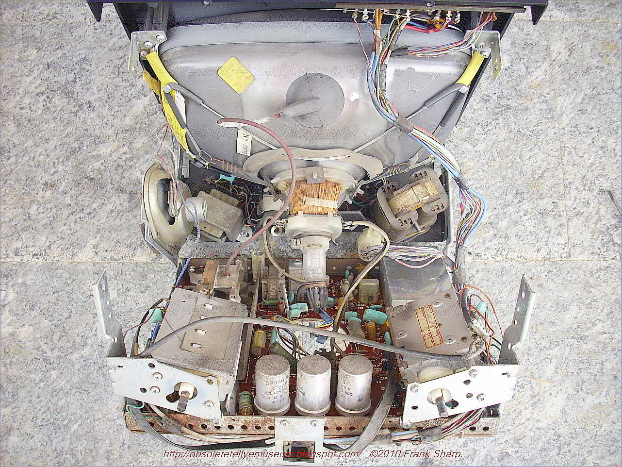
FIDES TU12P/B CHASSIS Z3468/A INTERNAL VIEW.


The chassis is realized on a monocarrier completely based around discretes semiconductors.


All semiconductors circuits were made by:ates and PHILIPS.

SGS is Società Generale Semiconduttori - Aquila Tubi E Semiconduttori (SGS-ATES, "Semiconductor General Society - Tubes and Semiconductors Aquila"), later SGS Microelettronica, a former Italian company now merged into STMicroelectronics
SGS Microelettronica and Thomson Semiconducteurs were both long-established semiconductor companies. SGS Microelettronica originated in 1972 from a previous merger of two companies:
  • ATES (Aquila Tubi e Semiconduttori), a vacuum tube and semiconductor maker headquartered in the Abruzzese city of l'Aquila, who in 1961 changed its name into Azienda Tecnica ed Elettronica del Sud and relocated its manufacturing plant in the outskirts of the Sicilian city of Catania
  • Società Generale Semiconduttori (founded in 1957 by Adriano Olivetti).


GENERAL BASIC TRANSISTOR LINE OUTPUT STAGE OPERATION:

The basic essentials of a transistor line output stage are shown in Fig. 1(a). They comprise: a line output transformer which provides the d.c. feed to the line output transistor and serves mainly to generate the high -voltage pulse from which the e.h.t. is derived, and also in practice other supplies for various sections of the receiver; the line output transistor and its parallel efficiency diode which form a bidirectional switch; a tuning capacitor which resonates with the line output transformer primary winding and the scan coils to determine the flyback time; and the scan coils, with a series capacitor which provides a d.c. block and also serves to provide slight integration of the deflection current to compensate for the scan distortion that would otherwise be present due to the use of flat screen, wide deflection angle c.r.t.s. This basic circuit is widely used in small -screen portable receivers with little elaboration - some use a pnp output transistor however, with its collector connected to chassis.

Circuit Variations:
Variations to the basic circuit commonly found include: transposition of the scan coils and the correction capacitor; connection of the line output transformer primary winding and its e.h.t. overwinding in series; connection of the deflection components to a tap on the transformer to obtain correct matching of the components and conditions in the stage; use of a boost diode which operates in identical manner to the arrangement used in valve line output stages, thereby increasing the effective supply to the stage; omission of the efficiency diode where the stage is operated from an h.t. line, the collector -base junction of the line output transistor then providing the efficiency diode action without, in doing so, producing scan distortion; addition of inductors to provide linearity and width adjustment; use of a pair of series -connected line output transistors in some large -screen colour chassis; and in colour sets the addition of line convergence circuitry which is normally connected in series between the line scan coils and chassis. These variations on the basic circuit do not alter the basic mode of operation however.

Resonance
The most important fact to appreciate about the circuit is that when the transistor and diode are cut off during the flyback period - when the beam is being rapidly returned from the right-hand side of the screen to the left-hand side the tuning capacitor together with the scan coils and the primary winding of the line output transformer form a parallel resonant circuit: the equivalent circuit is shown in Fig. 1(b). The line output transformer primary winding and the tuning capacitor as drawn in Fig. 1(a) may look like a series tuned circuit, but from the signal point of view the end of the transformer primary winding connected to the power supply is earthy, giving the equivalent arrangement shown in Fig. 1(b).

The Flyback Period:
Since the operation of the circuit depends mainly upon what happens during the line flyback period, the simplest point at which to break into the scanning cycle is at the end of the forward scan, i.e. with the beam deflected to the right-hand side of the screen, see Fig. 2. At this point the line output transistor is suddenly switched off by the squarewave drive applied to its base. Prior to this action a linearly increasing current has been flowing in the line output transformer primary winding and the scan coils, and as a result magnetic fields have been built up around these components. When the transistor is switched off these fields collapse, maintaining a flow of current which rapidly decays to zero and returns the beam to the centre of the screen. This flow of current charges the tuning capacitor, and the voltage at A rises to a high positive value - of the order of 1- 2k V in large -screen sets, 200V in the case of mains/battery portable sets. The energy in the circuit is now stored in the tuning capacitor which next discharges, reversing the flow of current in the circuit with the result that the beam is rapidly deflected to the left-hand side of the screen - see Fig. 3. When the tuning capacitor has discharged, the voltage at A has fallen to zero and the circuit energy is once more stored in the form of magnetic fields around the inductive components. One half -cycle of oscillation has occurred, and the flyback is complete.

Energy Recovery:
First Part of Forward Scan The circuit then tries to continue the cycle of oscillation, i.e. the magnetic fields again collapse, maintaining a current flow which this time would charge the tuning capacitor negatively (upper plate). When the voltage at A reaches about -0.6V however the efficiency diode becomes forward biased and switches on. This damps the circuit, preventing further oscillation, but the magnetic fields continue to collapse and in doing so produce a linearly decaying current flow which provides the first part of the forward scan, the beam returning towards the centre of the screen - see Fig. 4. The diode shorts out the tuning capacitor but the scan correction capacitor charges during this period, its right-hand plate becoming positive with respect to its left-hand plate, i.e. point A. Completion of Forward Scan When the current falls to zero, the diode will switch off. Shortly before this state of affairs is reached however the transistor is switched on. In practice this is usually about a third of the way through the scan. The squarewave applied to its base drives it rapidly to saturation, clamping the voltage at point A at a small positive value - the collector emitter saturation voltage of the transistor. Current now flows via the transistor and the primary winding of the line output transformer, the scan correction capacitor discharges, and the resultant flow of current in the line scan coils drives the beam to the right-hand side of the screen see Fig. 5.

Efficiency:
The transistor is then cut off again, to give the flyback, and the cycle of events recurs. The efficiency of the circuit is high since there is negligible resistance present. Energy is fed into the circuit in the form of the magnetic fields that build up when the output transistor is switched on. This action connects the line output transformer primary winding across the supply, and as a result a linearly increasing current flows through it. Since the width is
dependent on the supply voltage, this must be stabilised.

Harmonic Tuning:
There is another oscillatory action in the circuit during the flyback period. The considerable leakage inductance between the primary and the e.h.t. windings of the line output transformer, and the appreciable self -capacitance present, form a tuned circuit which is shocked into oscillation by the flyback pulse. Unless this oscillation is controlled, it will continue into and modulate the scan. The technique used to overcome this effect is to tune the leakage inductance and the associated capacitance to an odd harmonic of the line flyback oscillation frequency. By doing this the oscillatory actions present at the beginning of the scan cancel. Either third or fifth harmonic tuning is used. Third harmonic tuning also has the effect of increasing the amplitude of the e.h.t. pulse, and is generally used where a half -wave e.h.t. rectifier is employed. Fifth harmonic tuning results in a flat-topped e.h.t. pulse, giving improved e.h.t. regulation, and is generally used where an e.h.t. tripler is employed to produce the e.h.t. The tuning is mainly built into the line output transformer, though an external variable inductance is commonly found in colour chassis so that the tuning can be adjusted. With a following post I will go into the subject of modern TV line timebases in greater detail with other models and technology shown here at  Obsolete Technology Tellye !


- The EHT Output is realized with a selenium rectifier.

The EHT selenium rectifier which is a Specially designed selenium rectifiers were once widely used as EHT rectifiers in television sets and photocopiers. A layer of selenium was applied to a sheet of soft iron foil, and thousands of tiny discs (typically 2mm diameter) were punched out of this and assembled as "stacks" inside ceramic tubes. Rectifiers capable of supplying tens of thousands of volts could be made this way. Their internal resistance was extremely high, but most EHT applications only required a few hundred microamps at most, so this was not normally an issue. With the development of inexpensive high voltage silicon rectifiers, this technology has fallen into disuse.


Power supply is realized with mains transformer and Linear transistorized power supply stabilizer, A DC power supply apparatus includes a rectifier circuit which rectifies an input commercial AC voltage. The rectifier output voltage is smoothed in a smoothing capacitor. Voltage stabilization is provided in the stabilizing circuits by the use of Zener diode circuits to provide biasing to control the collector-emitter paths of respective transistors.A linear regulator circuit according to an embodiment of the present invention has an input node receiving an unregulated voltage and an output node providing a regulated voltage. The linear regulator circuit includes a voltage regulator, a bias circuit, and a current control device.

In one embodiment, the current control device is implemented as an NPN bipolar junction transistor (BJT) having a collector electrode forming the input node of the linear regulator circuit, an emitter electrode coupled to the input of the voltage regulator, and a base electrode coupled to the second terminal of the bias circuit. A first capacitor may be coupled between the input and reference terminals of the voltage regulator and a second capacitor may be coupled between the output and reference terminals of the voltage regulator. The voltage regulator may be implemented as known to those skilled in the art, such as an LDO or non-LDO 3-terminal regulator or the like.
The bias circuit may include a bias device and a current source. The bias device has a first terminal coupled to the output terminal of the voltage regulator and a second terminal coupled to the control electrode of the current control device. The current source has an input coupled to the first current electrode of the current control device and an output coupled to the second terminal of the bias device. A capacitor may be coupled between the first and second terminals of the bias device.
In the bias device and current source embodiment, the bias device may be implemented as a Zener diode, one or more diodes coupled in series, at least one light emitting diode, or any other bias device which develops sufficient voltage while receiving current from the current source. The current source may be implemented with a PNP BJT having its collector electrode coupled to the second terminal of the bias device, at least one first resistor having a first end coupled to the emitter electrode of the PNP BJT and a second end, a Zener diode and a second resistor. The Zener diode has an anode coupled to the base electrode of the PNP BJT and a cathode coupled to the second end of the first resistor. The second resistor has a first end coupled to the anode of the Zener diode and a second end coupled to the reference terminal of the voltage regulator. A second Zener diode may be included having an anode coupled to the cathode of the first Zener diode and a cathode coupled to the first current electrode of the current control device.
A circuit is disclosed for improving operation of a linear regulator, having an input terminal, an output terminal, and a reference terminal. The circuit includes an input node, a transistor, a bias circuit, and first and second capacitors. The transistor has a first current electrode coupled to the input node, a second current electrode for coupling to the input terminal of the linear regulator, and a control electrode. The bias circuit has a first terminal for coupling to the output terminal of the linear regulator and a second terminal coupled to the control electrode of the transistor. The first capacitor is for coupling between the input and reference terminals of the linear regulator, and the second capacitor is for coupling between the output and reference terminals of the linear regulator. The bias circuit develops a voltage sufficient to drive the control terminal of the transistor and to operate the linear regulator. The bias circuit may be a battery, a bias device and a current source, a floating power supply, a charge pump, or any combination thereof. The transistor may be implemented as a BJT or FET or any other suitable current controlled device.


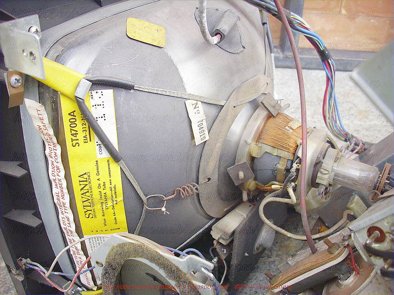
FIDES TU12P/B CHASSIS Z3468/A CRT TUBE SYLVANIA ST4700A.


-------------------------------------------------------------------------------------

Sylvania Electric Products was a U.S. manufacturer of diverse electrical equipment, including at various times radio transceivers, vacuum tubes, semiconductors, and mainframe computers. They were one of the companies involved in the development of the COBOL programming language.


Sylvania started as Hygrade Sylvania Corporation when NILCO, Sylvania and Hygrade Lamp Company merged into one company in 1931. In 1939, Hygrade Sylvania started preliminary research on fluorescent technology, and later that year, introduced the first linear, or tubular, fluorescent lamp ever made. It was featured at the 1939 New York World's Fair.


Sylvania was also a manufacturer of both vacuum tubes and transistors.

In 1942, the company changed its name to Sylvania Electric Products Inc. (note no comma)

In 1959, Sylvania Electronics merged with General Telephone to form General Telephone and Electronics (GTE)

Through merger and acquisitions, the Company became a significant, but never dominating supplier of electrical distribution equipment, including transformers and switchgear, residential and commercial load centers and breakers, pushbuttons, indicator lights and other hard-wired devices. All were manufactured and distributed under the brand name GTE Sylvania, with the name Challenger used for it light commercial and residential product lines.

GTE Sylvania contributed to the technological advancement of electrical distribution products in the late 70's with several interesting product features. At the time, they were the leading supplier of vacuum cast coil transformers, manufactured in their Hampton, VA plant. Their transformers featured aluminum primary winding and were cast using relatively inexpensive molds, allowing them to produce cast coil transformers in a variety of KVA capacities, primary and secondary voltages and physical coil sizes, including low profile coils for mining and other specialty applications. They also developed the first medium voltage 3 phase panel that could survive a dead short across two phases. Their pateneted design used bus bar encapsulated in a thin coating of epoxy and then bolted together across all three phases, using special non-conductive fittings.

By 1981 GTE had made the decision to exit the electrical distribution equipment market and began selling off its product lines and manufacturing facilities. The Challenger line, mostly manufactured at the time in Jackson, MS, was sold to a former officer of GTE, who used the Challenger name as the name of his new company. Challenger flourished, and was eventually sold to Westinghouse, and later Eaton Corporation. By the mid 80's the GTE Sylvania electrical equipment product line and name was no more.

In 1993 GTE exited the lighting business to concentrate on its core telecomms operations. The European, Asian and Latin American operations are now under the ownership of Havells Sylvania. With the acquisition of the North American division by Osram GmbH in January 1993 Osram Sylvania Inc. was established.

In the early 1980s, GTE Sylvania sold the rights to the name Sylvania and Philco for use on consumer electronics equipment only, to Holland's NV Philips. This marked the end of Sylvania's TV production in Batavia, NY, USA and Smithfield, NC, USA. The Sylvania Smithfield plant later became Channel Master. The rights to the Sylvania name in many countries are held by the U.S. subsidiary of the German company Osram which, itself, is a subsidiary of Siemens AG (NYSE:SI). The Sylvania brand name is owned worldwide, apart from Australia, Canada, Mexico, New Zealand, Puerto Rico and the USA, by Havells Sylvania, headquartered in London, England.


GTE Corporation (formerly General Telephone & Electronics Corporation) was the largest of the "independent" US telephone companies during the days of the Bell System. It acquired the third largest independent, Continental Telephone (ConTel) in 1991.[1] They also owned Automatic Electric, a telephone equipment supplier similar in many ways to Western Electric, and Sylvania Lighting, the only non-communications-oriented company under GTE ownership. GTE provided local telephone service to a large number of areas of the U.S. through operating companies, much like how American Telephone & Telegraph provided local telephone service through its 22 Bell Operating Companies.

The company also acquired BBN Planet, one of the earliest Internet service providers, in 1997. That division became known as GTE Internetworking, and was later spun off into the independent company Genuity (a name recycled from another Internet company GTE acquired in 1997) as part of the GTE-Bell Atlantic merger that created Verizon.

GTE operated in Canada via large interests in subsidiary companies such as BC TEL and Quebec-Téléphone. When foreign ownership restrictions on telecommunications companies were introduced, GTE's ownership was grandfathered. When BC Tel merged with Telus (the name given the privatized Alberta Government Telephones (AGT)) to create BCT.Telus, GTE's Canadian subsidiaries were merged into the new parent, making it the second-largest telecommunications carrier in Canada. As such, GTE's successor, Verizon Communications, was the only foreign telecommunications company with a greater than 20% interest in a Canadian carrier, until Verizon completely divested itself of its shares in 2004.[2]

In the Caribbean, CONTEL purchased several major stakes in the newly independent countries of the British West Indies (Namely in Barbados, Jamaica, and Trinidad and Tobago).[3][4][5]

Prior to GTE's merger with Bell Atlantic, GTE also maintained an interactive television service joint-venture called GTE mainStreet (sometimes also called mainStreet USA[citation needed]) as well as an interactive entertainment and video game publishing operation, GTE Interactive Media.


History

GTE's heritage can be traced to 1918, when three Wisconsin public utility accountants (John F. O'Connell, Sigurd L. Odegard, and John A. Pratt) pooled $33,500 to purchase the Richland Center Telephone Company, serving 1,466 telephones in the dairy belt of southern Wisconsin. In 1920 the three accountants formed a corporation, Commonwealth Telephone Company, with Odegard as president, Pratt as vice-president, and O'Connell as secretary. Richland Center Telephone became part of Commonwealth Telephone, which quickly purchased telephone companies in three nearby communities. In 1922 Pratt resigned as vice-president and was replaced by Clarence R. Brown, a former Bell System employee.

By the mid-1920s Commonwealth had extended beyond Wisconsin borders and purchased the Belvidere Telephone Company in Illinois. It also diversified into other utilities by acquiring two small Wisconsin electrical companies. Expansion was stepped up in 1926, when Odegard secured an option to purchase Associated Telephone Company of Long Beach, California and proceeded to devise a plan for a holding company, to be named Associated Telephone Utilities Company. An aggressive acquisition program was quickly launched in eastern, midwestern, and western states, with the company using its own common stock to complete transactions.

During its first six years, Associated Telephone Utilities acquired 340 telephone companies, which were consolidated into 45 companies operating more than 437,000 telephones in 25 states. By the time the stock market bottomed out in October 1929, Associated Telephone Utilities was operating about 500,000 telephones with revenues approaching $17 million.

In January 1930 a new subsidiary, Associated Telephone Investment Company, was established. Designed to support its parent's acquisition program, the new company's primary business was buying company stock in order to bolster its market value. Within two years the investment company had incurred major losses, and a $1 million loan had to be negotiated. Associated Telephone Investment was dissolved but not before its parent's financial plight had become irreversible, and in 1933 Associated Telephone Utilities went into receivership.


General Telephone

The company was reorganized that same year and resurfaced in 1935 as General Telephone Corporation, operating 12 newly consolidated companies. John Winn, a 26-year veteran of the Bell System, was named president. In 1936 General Telephone created a new subsidiary, General Telephone Directory Company, to publish directories for the parent's entire service area.

Like other businesses, the telephone industry was under government restrictions during World War II, and General Telephone was called upon to increase services at military bases and war-production factories. Following the war, General Telephone reactivated an acquisitions program that had been dormant for more than a decade and purchased 118,000 telephone lines between 1946 and 1950. In 1950 General Telephone purchased its first telephone-equipment manufacturing subsidiary, Leich Electric Company, along with the related Leich Sales Corporation.

By 1951, General Telephone's assets included 15 telephone companies operating in 20 states. In 1955 Theodore Gary & Company, the second-largest independent telephone company, which had 600,000 telephone lines, was merged into General Telephone, which had grown into the largest independent outside the Bell System. The merger gave the company 2.5 million lines. Theodore Gary's assets included telephone operations in the Dominican Republic, British Columbia, and the Philippines, as well as Automatic Electric, the second-largest telephone equipment manufacturer in the U.S. It also had a subsidiary, named the General Telephone and Electric Corporation, formed in 1930 with the Transamerica Corporation and British investors to compete against ITT.[9]

In 1959 General Telephone and Sylvania Electric Products merged, and the parent's name was changed to General Telephone & Electronics Corporation (GT&E). The merger gave Sylvania - a leader in such industries as lighting, television and radio, and chemistry and metallurgy - the needed capital to expand. For General Telephone, the merger meant the added benefit of Sylvania's extensive research and development capabilities in the field of electronics. Power also orchestrated other acquisitions in the late 1950s, including Peninsular Telephone Company in Florida, with 300,000 lines, and Lenkurt Electric Company, Inc., a leading producer of microwave and data transmissions system.

In 1960 the subsidiary GT&E International Incorporated was formed to consolidate manufacturing and marketing activities of Sylvania, Automatic Electric, and Lenkurt, outside the United States. During the early 1960s the scope of GT&E's research, development, and marketing activities was broadened. In 1963 Sylvania began full-scale production of color television picture tubes, and within two years it was supplying color tubes for 18 of the 23 domestic U.S. television manufacturers. About the same time, Automatic Electric began supplying electronic switching equipment for the U.S. defense department's global communications systems, and GT&E International began producing earth-based stations for both foreign and domestic markets. GT&E's telephone subsidiaries, meanwhile, began acquiring community-antenna television systems (CATV) franchises in their operating areas.

In 1964 GT&E president Leslie H. Warner orchestrated a deal that merged Western Utilities Corporation, the nation's second-largest independent telephone company, with 635,000 telephones, into GT&E. The following year Sylvania introduced the revolutionary four-sided flashcube, enhancing its position as the world's largest flashbulb producer. Acquisitions in telephone service continued under Warner during the mid-1960s. Purchases included Quebec Telephone in Canada, Hawaiian Telephone Company, and Northern Ohio Telephone Company and added a total of 622,000 telephone lines to GT&E operations. By 1969 GT&E was serving ten million telephones.

In March 1970 GT&E's New York City headquarters was bombed by a radical antiwar group in protest of the company's participation in defense work. In December of that year the GT&E board agreed to move the company's headquarters to Stamford, Connecticut.

After initially proposing to build separate satellite systems, GT&E and its telecommunications rival, American Telephone & Telegraph, announced in 1974 joint venture plans for the construction and operation of seven earth-based stations interconnected by two satellites. That same year Sylvania acquired name and distribution rights for Philco television and stereo products. GTE International expanded its activities during the same period, acquiring television manufacturers in Canada and Israel and a telephone manufacturer in Germany.

In 1976 newly elected chairman Theodore F. Brophy reorganized the company along five global product lines: communications, lighting, consumer electronics, precision materials, and electrical equipment. GTE International was phased out during the reorganization, and GTE Products Corporation was formed to encompass both domestic and foreign manufacturing and marketing operations. At the same time, GTE Communications Products was formed to oversee operations of Automatic Electric, Lenkurt, Sylvania, and GTE Information Systems. In 1979, another reorganization soon followed under new president Theodore F. Vanderslice. GTE Products Group was eliminated as an organizational unit and GTE Electrical Products, consisting of lighting, precision materials, and electrical equipment, was formed. Vanderslice also revitalized the GT&E Telephone Operating Group in order to develop competitive strategies for anticipated regulatory changes in the telecommunications industry.

In 1979, GTE purchased Telenet to establish a presence in the growing packet switching data communications business. GTE Telenet was later included in the US Telecom joint venture.


1980s

GT&E sold its consumer electronics businesses, including the accompanying brand names of Philco and Sylvania in 1980, after watching revenues from television and radio operations decrease precipitously with the success of foreign manufacturers. Following AT&T's 1982 announcement that it would divest 22 telephone operating companies, GT&E made a number of reorganization moves.

In 1982 the company adopted the name GTE Corporation and formed GTE Mobilnet Incorporated to handle the company's entrance into the new cellular telephone business. In 1983 GTE sold its electrical equipment, brokerage information services, and cable television equipment businesses. That same year, Automatic Electric and Lenkurt were combined as GTE Network Systems.

GTE became the third-largest long-distance telephone company in 1983 through the acquisition of Southern Pacific Communications Company. At the same time, Southern Pacific Satellite Company was acquired, and the two firms were renamed GTE Sprint Communications Corporation and GTE Spacenet Corporation, respectively. Through an agreement with the Department of Justice, GTE conceded to keep Sprint Communications separate from its other telephone companies and limit other GTE telephone subsidiaries in certain markets. In December 1983 Vanderslice resigned as president and chief operating officer.


1990s

In 1990 GTE reorganized its activities around three business groups: telecommunications products and services, telephone operations, and electrical products. That same year, GTE and Contel Corporation announced merger plans that would strengthen GTE's telecommunications and telephone sectors.

Following action or review by more than 20 governmental bodies, in March 1991 the merger of GTE and Contel was approved. Over half of Contel's $6.6 billion purchase price, $3.9 billion, was assumed debt. In April 1992, James L. "Rocky" Johnson retired after 43 years at GTE, remaining on the GTE board of directors as Chairman Emeritus. Charles "Chuck" Lee was named to succeed Mr. Johnson. Mr. Lee's first order of business was reduction of that obligation. He sold GTE's North American Lighting business to a Siemens affiliate for over $1 billion, shaved off local exchange properties in Idaho, Tennessee, Utah, and West Virginia to generate another $1 billion, divested its interest in Sprint in 1992, and sold its GTE Spacenet satellite operations to General Electric in 1994.

The Telecommunications Act of 1996, promised to encourage competition among local phone providers, long distance services, and cable television companies. Many leading telecoms prepared for the new competitive realities by aligning themselves with entertainment and information providers. GTE, on the other hand, continued to focus on its core operations, seeking to make them as efficient as possible.

Among other goals, GTE's plan sought to double revenues and slash costs by $1 billion per year by focusing on five key areas of operation: technological enhancement of wireline and wireless systems, expansion of data services, global expansion, and diversification into video services. GTE hoped to cross-sell its large base of wireline customers on wireless, data and video services, launching Tele-Go, a user-friendly service that combined cordless and cellular phone features. The company bought broadband spectrum cellular licenses in Atlanta, Seattle, Cincinnati and Denver, and formed a joint venture with SBC Communications to enhance its cellular capabilities in Texas. In 1995, the company undertook a 15-state test of video conferencing services, as well as a video dialtone (VDT) experiment that proposed to offer cable television programming to 900,000 homes by 1997. GTE also formed a video programming and interservices joint venture with Ameritech Corporation, BellSouth Corporation, SBC, and The Walt Disney Company in the fall of 1995.

Foreign efforts included affiliations with phone companies in Argentina, Mexico, Germany, Japan, Canada, the Dominican Republic, Venezuela and China. The early 1990s reorganization included a 37.5 percent workforce reduction, from 177,500 in 1991 to 111,000 by 1994. Lee's fivefold strategy had begun to bear fruit by the mid-1990s. While the communication conglomerate's sales remained rather flat, at about $19.8 billion, from 1992 through 1994, its net income increased by 43.7 percent, from $1.74 billion to a record $2.5 billion, during the same period.


Merger with Bell Atlantic

Bell Atlantic merged with GTE on June 30, 2000, and named the new entity Verizon Communications. The GTE operating companies retained by Verizon are now collectively known as Verizon West division of Verizon (including east coast service territories). The remaining smaller operating companies were sold off or transferred into the remaining ones. Additional properties were sold off within a few years after the merger. On July 1, 2010, Verzion sold many former GTE properties to Frontier Communications.

References:

"Bell Atlantic and GTE Pick Post-Merger Name". New York Times. April 4, 2000. Retrieved March 15, 2015.
"News Releases - Verizon News".

"GTE Corporation". Encyclopædia Britannica. Retrieved January 2, 2014.

"Investor Relations - Verizon".

"Bell Atlantic and GTE Chairmen Praise FCC Merger Approval". Verizon. Retrieved January 10, 2014.

"Sale of 73.5 million TELUS shares by Verizon completed". TELUS News Release. December 14, 2004.

Felipe M Noguera. "Telecommunications in The Caribbean".

Cable & Wireless Barbados: Early History

Telecommunications Services of Trinidad and Tobago - Corporate History

Linda Haugsted (1992-12-07). "Daniels Cablevision launches GTE Main Street. (package of interactive information services)". Multichannel News. Archived from the original on 2011-05-16.

"CREATIVE MULTIMEDIA AND GTE MAIN STREET STRIKE PARTNERSHIP; New agreement will deliver CD-ROMs over subscribers' TV sets". Business Wire. May 30, 1995.

Mike Farrell (May 24, 2004). "Sale of Cerritos Cable System Expected Soon". Multichannel News.

"GTE Corporation - Company History". Fundinguniverse.com. Retrieved February 24, 2017.

"Transamerica into Telephones," Time Magazine, 20 October 1930.

"Company History". Vintage Sylvania. Retrieved August 28, 2014.

FCC Internet Services Staff. "Corporate History - Verizon Communications (formerly GTE Corporation)". Fcc.gov. Retrieved May 15, 2012.

"Verizon must slash $375M in costs to stay on even keel following Frontier sale, Jefferies says". FierceTelecom.

Affiliated Interest Agreement - Advice No. 26. Verizon Northwest, Inc. Exhibit 1.

Saturday, August 4, 2012

SABA ULTRACOLOR T5669 I32 CM TELECOMMANDER YEAR 1978.


The SABA ULTRACOLOR T5669 I32 CM TELECOMMANDER is a heavy 22 inches color television with 32 (16 + 16) programs and VST search system with OSD tuning search bar and infrared remote.

The set was featuring the CM110 chassis with complete modular design.

The set has even an audio output of 10watt and front jacks for audio recorder and headphones.


It was first SABA television with a monocarrier tv modular chassis with isolated from mains SMPS power supply circuit with modular design. The CM designator was saying "Computer Modular" explaining the fact that these TV Chassis series was designed with the help of Computer aided design for first time (These computers have had nothing to do with modern machines, they were big like a room and with monochrome green screens and with pen light to pinpoint screen graphical areas).

 The set is a first in featuring  a new set of PAL decoder chips which has been introduced by Siemens, the TDA2560/TDA2522/TDA2530. The first two of these second -source the latest Philips/Mullard decoder i.c.s, with the TDA2560 as luminance and chrominance signal amplifier and the TDA2522 as the reference oscillator/chrominance demodulator. Interesting features of this set up are the fact that the burst signal passes through the chrominance delay line and the fact that the reference oscillator operates at 8.86MHz, a digital divider providing exactly 90° phase displaced 4.43MHz outputs without the need for a phase shift coil. The first UK produced chassis to use these i.c.s is the Tandberg CTV3, the larger UK setmakers staying for the time being with the TBA560C/TBA540/TCA800 combination. The third i.c. from Siemens is the TDA2530 which supersedes the well known TBA530 luminance/colour-difference signal matrix- ing i.c. The TDA2530 contains a negative feedback driver amplifier and internal clamping in addition to the matrixing network.

The set is build with a Modular chassis design because as modern television receivers become more complex the problem of repairing the receiver becomes more difficult. As the number of components used in the television receiver increases the susceptibility to breakdown increases and it becomes more difficult to replace defective components as they are more closely spaced. The problem has become even more complicated with the increasing number of color television receivers in use. A color television receiver has a larger number of circuits of a higher degree of complexity than the black and white receiver and further a more highly trained serviceman is required to properly service the color television receiver.
Fortunately for the service problem to date, most failures occur in the vacuum tubes used in the television receivers. A faulty or inoperative vacuum tube is relatively easy to find and replace. However, where the television receiver malfunction is caused by the failure of other components, such as resistors, capacitors or inductors, it is harder to isolate the defective component and a higher degree of skill on the part of the serviceman is required.
Even with the great majority of the color television receiver malfunctions being of the "easy to find and repair" type proper servicing of color sets has been difficult to obtain due to the shortage of trained serviceman.
At the present time advances in the state of the semiconductor art have led to the increasing use of transistors in color television receivers. The receiver described in this application has only two tubes, the picture tube and the high voltage rectifier tube, all the other active components in the receiver being semiconductors.
One important characteristic of a semiconductor device is its extreme reliability in comparison with the vacuum tube. The number of transistor and integrated circuit failures in the television receiver will be very low in comparison with the failures of other components, the reverse of what is true in present day color television receivers. Thus most failures in future television receivers will be of the hard to service type and will require more highly qualified servicemen.
The primary symptoms of a television receiver malfunction are shown on the picture tube of the television receiver while the components causing the malfunction are located within the cabinet. Also many adjustments to the receiver require the serviceman to observe the screen. Thus the serviceman must use unsatisfactory mirror arrangements to remove the electronic chassis from the cabinet, usually a very difficult task. Further many components are "buried" in a maze of circuitry and other components so that they are difficult to remove and replace without damage to other components in the receiver.
Repairing a modern color television receiver often requires that the receiver be removed from the home and carried to a repair shop where it may remain for many weeks. This is an expensive undertaking since most receivers are bulky and heavy enough to require at least two persons to carry them. Further, two trips must be made to the home, one to pick up the receiver and one to deliver it. For these reasons, the cost of maintaining the color television receiver in operating condition often exceeds the initial cost of the receiver and is an important factor in determining whether a receiver will be purchased.
Therefore, the object of this invention is to provide a transistorized color television receiver in which the main electronic chassis is easily accessible for maintenance and adjustment. Another object of this invention is to provide a transistorized color television receiver in which the electronic circuits are divided into a plurality of modules with the modules easily removable for service and maintenance. The main electronic chassis is slidably mounted within the cabinet so that it may be withdrawn, in the same manner as a drawer, to expose the electronic circuitry therein for maintenance and adjustment from the rear closure panel after easy removal. Another aspect is the capability to be serviced at eventually the home of the owner.
The PHILIPS 20AX system was introduced in Europe as the first self converging picture tube/deflection coil, combination for 110° degree deflection and screen sizes up to 26". The system is based on the automatic convergence principle discovered by Haantjes and Lubben of Philips Research Laboratory more than 20 years ago. It makes use of an in-line gun array in conjunction with a specially designed saddle type deflection coil. Residual small tolerance errors are compensated by a simple dynamic four-pole system. The tube is 2 cm shorter than conventional 110° Degree tubes and has a standard 36.5 mm neck in order to obtain good color selection. A slotted mask is used in combination with a stripe-structure screen. Picture sharpness is ensured by an astigmatic electron gun.

All transistor color VHF/UHF TV receiver powered from AC net 220V/50Hz.Woodencabinet.


The Schwarzwälder Apparate-Bau-Anstalt (SABA) was a German manufacturer for electronic equipment founded in 1923 at Triberg im Schwarzwald (Black Forest), present-day Baden-Württemberg.

The former clock maker began producing component parts for broadcast receivers until it acquired a manufacturing license for complete radio sets in 1927. SABA quickly expanded, moved to a larger factory building at Villingen in 1932 and over the years became a long-time rival of the leading Telefunken company. After World War II the firm entered into the production of tape recorders, television sets and even established a record label, the later MPS Records company.

When faced with increasing competitive pressure, the shareholders sold the majority of the company to the GTE Corporation in order to generate synergy effects with GTE's Sylvania brand. Nevertheless in 1980 the remaining tv set production was finally purchased by Thomson SA.


HISTORY OF  Schwarzwälder Apparate-Bau-Anstalt (SABA) IN GERMAN:

Von Wolfgang Menzel gibt es seit 1995 das Buch «SABA, die Produktion von 1924-1949» [506]. Es enthält mehr als 100 Gerätefotos und Details zu den Selbstbaugeräten. Die Firmengeschichte ist durch Hermann Brunner-Schwer eindrücklich im Buch «SABA, Bilanz einer Aufgabe» [481] festgehalten. Er ist einer der beiden Söhne der einzigen Tochter von Familie Hermann Schwer. Peter Zudeick hat wegen vorzeitigem Tod des Unternehmers vor allem das wirtschaftliche Umfeld dieser Geschichte beleuchtet. Das Buch ist jedem an der Radiogeschichte Deutschlands interessierten Leser zu empfehlen. Es liest sich wie ein Wirtschaftskrimi.

Zudem hat 1973 Sissi Hörzinger an der Universität Regensburg eine Diplomarbeit über die Produktpolitik von SABA geschrieben [497]. Allerdings verschweigen beide Werke Millionenverluste mit Fehlplanungen in den USA und die Diplomarbeit beschreibt weitere Fehlinvestitionen nur am Rande.

Die ersten Schritte des Familienunternehmens SABA gehen auf die Gründung einer Uhrenfabrik in Triberg durch Joseph Benedikt Schwer für sog. «Jockele-Uhren» im Jahre 1835 zurück.

1864 tritt der Sohn, August Schwer als gelernter Uhrmacher ein und 1865 nennen sie den Betrieb August Schwer Söhne Metallwaren-Fabrik. In den 80er Jahren des 19. Jahrhunderts erweitert Sohn August die Produktion mit verwandten Artikeln wie Briefwaagen und kleineren Metallfabrikaten.

Hermann Schwer (gel. Uhrmacher), der Enkel des Firmengründers, leitet den Betrieb von 20 Mitarbeitern ab 1905 im Alter von 27 Jahren. Er gliedert eine Herstellung von Rasierapparaten, Türklingeln und Fahrradglocken an.

Auf einer Reise nach Zürich im Frühjahr 1923 erhält Hermann Schwer den entscheidenden Impuls: Er hört im Studio von Telefunken über ein Detektorgerät eine vom Sender des Pariser Eiffelturms ausgestrahlte Musiksendung. Darauf beginnt er mit der Herstellung von Einzelteilen wie Stiel- [186] und Doppelkopfhörern, später auch von NF-Trafos (NT1, 2 und 3), Drehkondensatoren, Spulen und Widerständen etc. für den Verkauf an Radiobastler.

Für die Produkte wirbt die Firma mit den vier ersten Anfangsbuchstaben des Firmennamens: SABA. Das Werk beschäftigt 1923 ca. 200 Mitarbeiter.

Ab 1926 bietet SABA fertige Selbstbausätze mit Aufbau nach Browing-Drake aus den USA. 1927 erhält die Firma die Bauerlaubnis und bietet nun auch fertige Radios an - mit dabei auch ein KW-Audion. Eine Werbung von 1927 in Japan bezeugt, dass SABA frühzeitig an weltweiten Export dachte.

1929 verpflichtet SABA «einen hochbegabten Dipl.-Ing.» [481-21] aus der Schweiz, Eugen Leuthold. Er entwickelt unter der Typenbezeichnung (S)35 einen Apparat, der auf der Leipziger Frühjahrsmesse 1931 wegen seines überaus grossen Erfolges den Beinamen «Sieger» erhält. Bis Ende Jahr verkauft die Firma mehr als 100'000 dieser Geräte mit für Deutschland neuartigem Schaltungskonzept eines rückgekoppelten Anodengleichrichters mit Kathodengegenkopplung. SABA verwendet ein dynamisches Lautsprechersystem nach den Patenten von Rice-Kellog, USA [1-61+103].

1931 zeigt die Modellreihe S41 (31W, 44, T44) von Leuthold den ersten automatisch geregelten Schwundausgleich (AGC, aut. gain control) auf dem deutschen Markt. Ab diesem Jahr stellt SABA für jede neue Modellreihe eine Kundendienstschrift mit Reparaturanleitung bereit. Dies zieht sich bis in die Nachkriegsjahre. Allerdings sind Exportgeräte, wie z.B. 450WLK von 1938, nicht enthalten.

1932 kann SABA aus Gewinnen mit S35 und Nachfolgetypen die Investitionen für ein Hauptfabrikgebäude und diverse Nebengebäude planen und 1932/33 sowie 1934/35 realisieren. Der Umsatz beträgt nun 11,4 Mio. RM; SABA betont die «Schwarzwälder Präzision» und beschäftigt gegen 500 Mitarbeiter. Leider baut die Firma in den Jahren 1933-38/39 Drehkondensatoren aus Zinkguss. Diese sind heute unbrauchbar, wenn sie Feuchtigkeit ausgesetzt waren/sind.

SABA kommt in den entscheidenen Rundfunkjahren 1932 bis 1935 auf einen Marktanteil von rund 10% (1932 12,3%) und liegt damit knapp vor Mende an zweiter Stelle hinter Telefunken mit 12 bis 17%. 1935 entsteht eine Festschrift [498] zum 100-jährigen Jubiläum. Daraus geht hervor, dass in 13 Ländern SABA-Vertretungen bestehen.

1936 stirbt Hermann Schwer und seine Frau Johanna wird Universalerbin, jedoch mit verschiedenen Bestimmungen, u.a. dass die beiden Enkel, Hansjörg (1927) und Hermann Brunner-Schwer (1929) am 3.10.54 die Erbfolge antreten. Margarethe Brunner-Schwer, die einzige Tochter, lässt der Erblasser aus. Ihr geschiedener Mann, Fritz Brunner, war Musikdirektor. Johanna Schwer ernennt den techn. Leiter, Josef Fricker, zum Geschäftsleiter.

1936 gibt es gemäss Kundendienstschrift den bei «LSf» erwähnten 241GW nicht (sondern GWL), ebenfalls keinen 441WLK (nur WL). Der Zusatz T steht für Truhe, TS für Truhe mit Schallplatten-Laufwerk (2 Saisons). Der Zweikreiser 340WL verfügt über einen Empfindlichkeits- und Bandbreitenregler. Die Kundendienstschrift erwähnt, dass Mod. 242WL in den Ersatzteillisten vorkommt, jedoch nicht auf den Markt kam.

1938 entsteht der millionste SABA-Apparat. Die Firma verwendet nun statt Differential-Kondensatoren ein regelbares Dreifachbandfilter sowie NF-Gegenkopplung und bringt ihren letzten Geradeaus-Empfänger.

1939 erweitert SABA den Betrieb im Auftrag der Wehrmacht und 1940 beträgt die Kriegsproduktion 88%. Es entstehen Funkgeräte, UKW-Empfänger und -Sender für Panzer, Feldtelefone, Bordsprechanlagen, Suchgeräte etc.

1943 entfallen vom Gesamtumsatz von 22 Mio. RM lediglich 332'000 auf zivile Rundfunkproduktion. Johanna Schwer stirbt am 10.10.43. 1944 liegt der Umsatz mit 19 Mio. RM noch über dem Vorkriegsergebnis; Fricker ersetzt man durch Ernst Scherb. Ein wichtiges Zivilgerät bildet von 1941-44 das von Philips übernommene «Auslagerungs-Modell» 208U mit der SABA-Bezeichnung 500ZGW (aber gemäss [506] keine Eigenproduktion).

Am 19.4.45 vernichten zwei Volltreffer vor allem die kürzlich erstellten Werksbauten; dem Verwaltungsgebäude fehlt das Dach. Erst gegen Ende 1945 kann SABA einen Spielzeugkran, Tablettenröhrchen und andere Kleinigkeiten herstellen, dann bekommt die Firma ein Kontingent zur Herstellung von Fernsprechapparaten. Der im Krieg in die Schweiz zurückgekehrte Eugen Leuthold ist einverstanden, wieder zu SABA zu gehen, wenn diese die Erlaubnis zur Herstellung von Rundfunkgeräten erhält.

In [FT4601+02] sind die Vorkriegsgeräte 582WK, WKRO und S461GWK-AM erwähnt, die jedoch gemäss [481] SABA erst Ende 1947 fabrizieren kann, was auch [506] übernimmt.

Im April 1947 gründen die Eigner die SABA-Vertriebs GmbH, um während eines langwierigen Entnazifizierungsverfahrens einige frei verfügbare Mittel ansammeln zu können. Gegen Ende 1947 erhält SABA von der französischen Militärbehörde den Auftrag, ausschliesslich für Angehörige der französischen Besatzungsarmee Radios zu produzieren. Die Franzosen lassen jedoch stillschweigend zu, dass SABA Geräte für Kompensationsgeschäfte abzweigt. Die Geräte sind praktisch identisch mit der Vorkriegsserie [481-190]. 1948 gibt es neue, rundliche Formen. Zudem ist die Produktion nun von Einschränkungen frei.

1949 wandelt sich die unter der Obhut des Testamentvollstreckers stehende Einzelfirma in eine GmbH um. SABA-Geräte erleben einen reissenden Absatz; der Umsatz beträgt mehr als 21 Mio. DM und der Betrieb beschäftigt wie vor dem Krieg etwa 1000 Personen.

Wegen Verfall der Absorber-Patente von Elektrolux (Schweden) zieht SABA 1950 ein Kühlschrankprogramm auf, doch gibt es erhebliche Probleme und wenig Synergieeffekte, sondern Verluste.

SABA belegt nach Anteilen der auf den Markt gelangten Rundfunkgeräte gemäss [497] hinter Grundig (27%), Nord-Mende (12) und evtl. Loewe-Opta (11) den dritten/vierten Platz (11). Hermann Brunner-Schwer tritt in die Firma ein. Sein (späterer) Stiefvater, Ernst Scherb, lässt sich das schlechte Geschäft mit den Kühlschränken jedoch nicht ausreden. Damit gibt es viele Spannungen.

Ab Saison 1954/55 (Typen Freiburg und Bodensee) bringt SABA wieder Geräte mit Sendersuchlauf und automatischer Scharfabstimmung, wobei die meisten mit Fernbedienung ausrüstbar sind [638754]. 1966-70 baut die Firma den vollstransistorisierten Stereoempfänger «HiFi-Studio Freiburg Stereo» als letzten dieser Reihe. In [638754] sind die Modelle beschrieben und in einer Tabelle zusammengefasst.

1956 beginnt das «Werk 3», ein neu erstellter Betrieb in Friedrichshafen, mit der Produktion von selbst entwickelten Tonbandgeräten (sabafon). Erst 1957 gibt SABA das «Kühlschrankgeschäft» mit grossen Verlusten auf und beginnt in den frei werdenden Räumlichkeiten SABA-TV herzustellen. SABA stösst jedoch auf einen Verdrängungswettbewerb und kann die fetten Jahre der grossen Nachfrage nicht nutzen.

Erst 1960 kommt das Unternehmen mit einem Koffergerät auf den Markt. Nach dem 125jährigen Firmenjubiläum vom Oktober 1960, d.h. am 1.1.61 kann Hermann Brunner-Schwer die Geschäftsleitung übernehmen. Gemäss [497] treten die Brüder Brunner-Schwer allerdings 1955 in die Geschäftsleitung ein. Nun beginnen aber gerade die Warenhäuser billige Fernsehgeräte anzubieten, da Körting an Neckermann liefert und damit das Kartell aufbricht. Die erfolgreiche Antwort ist eine starke Bindung der Grosshändler an SABA und das Aufkaufen von SABA-Geräten aus Warenhäusern mit gleichzeitigem Lieferstopp an Händler, die sich nicht an die Abmachungen halten.

1961 kann SABA einen per Zufall entdeckten Effekt nutzen, indem sie ein speziell gerilltes Plastik verwendet, um unter dem Schlagwort «Sabavision» ein «zeilenfreies Fernsehen» anzubieten, das vorerst durch Patentschutz ohne Nachahmung bleibt. Die Belegschaft beträgt nun 4500 Personen; SABA zählt zu den wichtigsten TV-Anbietern. Trotzdem steht es schlecht; die Eigenmittel sind zu gering.

Am 18.5.62 versucht die Firma ihr Wohl mit einer engeren Bindung an 130 Grossisten und 9000 Einzelhändler (von 500 bzw. 20'000), da Ende der 50er Jahre allgemein die Preisbindung aufhört. Damit kann SABA tatsächlich den Umsatz von 118 Mio. DM auf 155 im Jahre 1965 steigern, doch sind Schwarz-Weiss-TV immer schwieriger abzusetzen, obwohl die Firma dafür hinter Nordmende als Nummer zwei gilt.

1964 kommt das Unternehmen mit «SABAmobil», einem Tonband-Radiokombi für Autos auf den Markt, doch löst die auch dann neu eingeführte Philips-Kassette das Gerät innerhalb drei Jahren ab.

Der Exportanteil von SABA beträgt Mitte der 60er Jahre etwa 15%. Die Firma versucht sich zusammen mit ADDO an einem elektronischen Tischrechner mit Druckwerk «ADDO-SABAtronic».

1967 ist der Einstieg ins Farbfernsehgeschäft für die ganze Branche problematisch, denn Neckermann bietet ein von Körting hergestelltes Gerät unter 2000 DM an. SABA bekommt technische Probleme aufgrund falsch dimensionierter Baugruppen. Zudem stocken Verhandlungen mit Telefunken betreffend direkter Beteiligung.

1967 platzt wegen einer heimlichen Intervention durch Max Grundig ein unterschriftsreifes, gutes Abkommen mit Philips. Grundig will einen 50 %-Anteil an SABA und darum Telefunken im Spiel halten!

Am 20.1.68 erzielt SABA ein Beteiligungs-Abkommen mit GTE (85 %) in den USA (mit Sylvania-Bildröhrenwerk in Belgien), das die Firmeneigner unter Verschwiegenheit aushandeln konnten. Die Qualität der TV-Geräte ist nun gut, die Umsätze steigern sich bis 1973 dank dem «Onkel aus Amerika» auf eine halbe Milliarde DM.

6000 Personen sind in den Werken Villingen, Friedrichshafen, Leutkirch, Tienen (Belgien), Kölliken und Aarau (je Schweiz) beschäftigt. 1972 belegt SABA im Bereich Rundfunk-Fernsehen-Tonband für das Inland hinter Grundig (14,7%), Telefunken (13,3%) und Philips (12,5%) zusammen mit Nordmende (je 9,3%) den vierten Platz. Japanische Unternehmen drängen mit Billiggeräten auf den deutschen Markt.

1974 ordern die Händler wegen dem bevorstehenden Fussballspektakel soviele Farb-TV-Geräte wie noch nie, doch weisen nun die Sylvania-Bildröhren eine grosse Anzahl von Ausfällen auf. SABA verliert viel Zeit mit der Beweisführung, dass es an den Bildröhren und nicht an den Geräten liegt. Dazu kommt ein persönliches Intriegenspiel und Hermann Mössner - von H. Brunner-Schwer ursprünglich an GTE empfohlen - übernimmt die Leitung von SABA. Unter seiner Regie entstehen grosse Verluste.

1980 trennt sich GTE von der Unterhaltungselektronik und verkauft diesen Teil samt SABA an den französischen Konzern Thomson-Brandt. Nachdem Thomson auch Telefunken übernimmt, lässt sie dort produzieren; SABA gibt es danach nur noch als Vertriebsgesellschaft und -Marke.


" Dank guter Qualitätsarbeit und innovativen Schaltungen sowie einem guten Marketing erreicht SABA 1932 bis 1935 hinter Telefunken den grössten Marktanteil in Deutschland. Auch in den 50er Jahren arbeitet SABA sehr erfolgreich, doch die 60er Jahre sind von finanziellen Schwierigkeiten geprägt. 1835: Ursprung in Triberg;
1865: August Schwer Söhne Metallwaren-Fabrik.
1918: Firmierung unter Schwarzwälder-Apparate-Bau-Anstalt, August Schwer & Söhne, Villingen.
1933: Schwarzwälder-Apparate-Bau-Anstalt August Schwer Söhne GmbH; Kurzform: SABA Radio Werke;
1950: Kurzform: SABA Werke.
Radios: 1927 bis 1979."

Some References.......

Rye, Howard (2002). Kernfeld, Barry (ed.). The New Grove Dictionary of Jazz. 3 (2nd ed.). New York: Grove's Dictionaries Inc. p. 172. ISBN 1-56159-284-6.

Literatur

  • Hermann Brunner-Schwer: SABA. Bilanz einer Aufgabe. Vom Aufstieg und Niedergang eines Familienunternehmens. Elster, Moos 1990. ISBN 3-89151-101-9 (Geschichte)
  • Hans Heinrich Schmid: Lexikon der Deutschen Uhrenindustrie 1850–1980. Firmenadressen, Fertigungsprogramm, Firmenzeichen, Markennamen, Firmengeschichten. Förderkreis Lebendiges Uhrenindustriemuseum e. V., Villingen-Schwenningen 2005. ISBN 3-927987-91-3
  • Farbfernsehtechnik, ganz einfach! Franzis, München.
  • Investitionen nur aus eigener Kraft. In: Die Zeit, Nr. 39/1960

Einzelnachweise:


Ehrenbürger Hermann Schwer In: Museumsverein Meersburg (Hrsg.): Meersburger Spuren. Verlag Robert Gessler, Friedrichshafen, 2007. ISBN 978-3-86136-124-4, S. 240–241.
SABA Sieger S35W auf radiomuseum.org, abgerufen am 6. April 2015
SABA Wildbad 8 auf radiomuseum.org, abgerufen am 6. April 2015
http://www.sozialgeschichte-uhrenindustrie.de/2016/02/14/die-saba-vom-familienbetrieb-zum-spielball-der-konzerne/
Schauinsland W II auf radiomuseum.org, abgerufen am 6. April 2015
Schwarzwaldmuseum Triberg
Ehrenbürger Hermann Schwer In: Museumsverein Meersburg (Hrsg.): Meersburger Spuren. Verlag Robert Gessler, Friedrichshafen, 2007. ISBN 978-3-86136-124-4, S. 240–241.
Eberhard Stadler: Firmen gehen, die Kantine bleibt. In: Südkurier vom 24. September 2009.
Markenregister SABA

Weblinks:


- Sammlung von Bildern, Videos und Audiodateien Firmengeschichte von SABA bei radiomuseum.orgWumpus Welt der Radios: Freiburg Automatic-Modelle, Jahrzehnte-Liste