Majority of fault were caused by dry joint which may cause conseguent
other faults not specifically related to the culprit point.
Picture
produced on the screen were very good and very bright for long times,
but as said before they have a discrete high rate of fault (BUT NEVER
LIKE ACTUAL CRAP LCD).
Right side
- LINE DEFLECTION TRAFO + EHT + N/S CORRECTION UNIT + SUPPLY + FRAME + E/W
Left side
- STEREO SOUND UNIT + TUNER + IF UNIT
uCONTROLLER
Center
- TA8659CN + TELETEXT UNIT + SCART SOCKET UNIT
MODELS FEATURING AND USING THE THOMSON CHASSIS ICC8 / Saba M5528, M5530VT, M6330VT, M7030VT, M7228VT, SB9221, SM258, T6355,
T7048, T7048NIC, T7055
Ferguson 59SL2, A59N, B51NX, B58N, B59F, B59N, B59NX, B68N, B68NX, C51N,
C51NX, C59NX, C68NX, / Nordmende 63BP, ST63V CHASSIS F23+ (ICC8/DE) /
Telefunken
A520V, BS351V, FS425MV, FS430V ?, FS435MV, FS525MV, FS535MV, MP216, MP254,
MS284, S1540, S258A, S298, S299, S545M, SM218, SM258, SMX258, SR255, SR285 /
Thomson Prestige 2000
Micom - ST6395B1
SMPS - TEA2261
Video - TA8659CN
Vertical - TDA8178
Sound - TDA2030
Tuner - MTP-MM-2015-01
FBT - 40308-11 (HR6354)
HOT - 2SD1546
RGB VIDEO AMPL :TEA5101A
TELEFUNKEN SR285 (ICC8) CHASSIS THOMSON ICC8 VIDEO CRT DRIVE CONTROL CDI2000 TOSHIBA TA8751AN:


TOSHIBA TA8751AN
TOSHIBA BIPOLAR LINEAR INTEGRATED CIRCUIT SILICON MONOLITHIC
TA8751AN
AUTOMATIC KINE BIAS (AKB)
RGB INTERFACE+
TA8751AN possesses functions that optimize the CRT
drive conditions in televisions, and is an IC that
automates the previously complex cutoff adjustment and
drive adjustment non-adjustment. .
It has an RGB TEXT input pin, so TV signal and TEXT ignal can be switched between rapidly.
AKB (AUTOMATIC KINE BIAS) Circuits take the previously complex adjustment of CRT drive
circuits and automates by absorbing the 3-color dispersion of the CRT. It is therefore
necessary to design the CRT drive circuit in an AKB centered state to allow efficient
absorption of the CRT's dispersion.
The primary color input on the TV side takes the form of DC coupling, so please set input
levels so that the contrast control and brightness control in previous stages are under the
following conditions in the center.
The TV's primary colors are DC coupled, so brightness
control from previous stages can be utilized.
hen the power is off and the CRT is
not warmed up, as a beam current
does not flow to cutoff and drive
detection interval, voltage is not
obtainable from the sense pin.

Accordingly, for operation so that
current flows to the CRT for both cut
adjustment and drive adjustment, the
CRT starts from a white screen the
instant it warms up.
In order to prevent this, the soft start
circuit returns the output DC voltage
and operates so that if pin 17 exceeds
a fixed value, cutoff adjustment is
fixed on the black side.
Vertical blanking input
Input pin for the vertical blanking
pulse that determines the timing of
the reference pulse for the cutoff
adjustment and drive adjustment.
The first 2H interval
after the leading
edge of the vertical blanking is the
cutoff reference level, while the next
2H interval is the drive reference
level.
H timing is created by the horizontal
blanking of pin 14.
B sense
G sense
R sense
Detection pin for the CRT beam
current.
The current that flows to the CRT
cathode as a result of the reference
pulse inserted for cutoff adjustment
and drive adjustment is converted to a
voltage and detected by detection
resistance. White balance can be
changed by varying detection
resistance.
The internal comparator operates in
tune with the timing of the reference
pulse.
VIDEO CRT DRIVE CONTROL CDI2000 TOSHIBA TA8751AN: Automatic white control circuit for color television receiver
A
color television receiver with automatic reference white control
circuit has negative feedback loops for automatically adjusting the
amplitude of each cathode driving voltage of R, G and B electron guns,
so that the magnitude of each cathode current of R, G and B electron
guns is converged to a given value. According to the negative feedback
operation, an adjusted reference white becomes insensitive to changes in
the cathode emission of CRT due to aging.
Inventors: Umezawa, Toshimitsu (Kazo, JP) Kabushiki Kaisha Toshiba (Kawasaki, JP)

1. An automatic white control circuit for a color CRT provided with red, green and blue cathodes, comprising:
color signal source means for providing red, green and blue color signals;
amplitude/level
controller means for controlling the amplitude of each of said red,
green and blue color signals in accordance with given red, green and
blue amplitude control signals, and for controlling the DC level of each
of said red, green and blue color signals in accordance with given red,
green and blue level control signals, thereby generating red, green and
blue amplitude and level-controlled signals;
a CRT drive circuit
for driving each of the red, green and blue cathodes of said color CRT
in accordance with said red, green and blue amplitude and
level-controlled signals;
current detector means for detecting a
current of each of said red, green and blue cathodes, and for providing
red, green and blue cathode current indicative signals;
pulse
generator means for generating: (1) a first reference pulse having a
first amplitude, (2) a second reference pulse having a second amplitude
which differs from said first amplitude, (3) a first gate pulse
generated in synchronism with said first reference pulse, and (4) a
second gate pulse generated in synchronism with said second reference
pulse;
a pulse insertion means for inserting said first and
second reference pulses into each of said red, green and blue color
signals;
means for sampling, in accordance with said first gate
pulse, each signal level of said red, green and blue cathode current
signals to provide red, green and blue DC level control potentials, and
for sampling, in accordance with said second gate pulse, each signal
level of said red, green and blue cathode current signals to provide
red, green and blue amplitude control potentials;
first
comparator means for comparing each of said red, green and blue level
control potentials with a first given reference potential, and for
providing said given red, green and blue level control signals, thereby
forming DC negative feedback control loops for controlling each bias of
the red, green and blue cathodes of said color CRT; and
second
comparator means for comparing each of said red, green and blue
amplitude control potentials with a second given reference potential,
and for providing said given red, green and blue amplitude control
signals, thereby forming AC negative feedback control loops for
controlling each amplitude of the red, green and blue cathode currents
of said color CRT,
wherein the automatic white control for said
color CRT is effected by the operation of said DC negative feedback
control loops, whose control targets are defined by said first given
reference potential, and by the operation of said AC negative feedback
control loops whose control targets are defined by said second given
reference potential.
2. An automatic white control circuit
according to claim 1, wherein the first amplitude of said first
reference pulse is larger than the second amplitude of said second
reference pulse.
3. An automatic white control circuit according
to claim 1, wherein the second amplitude of said second reference pulse
is larger than the first amplitude of said first reference pulse.
4.
An automatic white control circuit according to claim 1, wherein said
first reference pulse is generated after the generation of said second
reference pulse.
5. An automatic white control circuit according
to claim 1, wherein said second reference pulse is generated after the
generation of said first reference pulse.
6. An automatic white
control circuit according to claim 1, wherein said amplitude/level
controller includes a level controller for adjusting said red, green and
blue color signals based on said red, green and blue level control
signals, so that each DC level of said red, green and blue color signals
is converged to a value corresponding to said first given reference
potential.
7. An automatic white control circuit according to
claim 1, wherein said amplitude/level controller includes an amplitude
controller for adjusting said red, green and blue color signals based on
said red, green and blue amplitude control signals, so that each
amplitude of said red, green and blue color signals is converged to a
value corresponding to said second given reference potential.
Description:
BACKGROUND OF THE INVENTION
The present invention relates to an improvement of a color television receiver having an automatic white control circuit.
In
a conventional color television receiver of an NTSC / PAL television
system, a reference white color temperature of a CRT is set to be
6,774K, for example. The reference white of the color temperature is the
basis for color reproduction. Deviation between the CRT reference white
color temperature and the color temperature of 6,774K results in a
color misregistration between the original color of a photographed
object and the color reproduced by the television receiver. Therefore,
the reference white must be accurately maintained at a predetermined
value.
A
color CRT of the color television receiver is driven by red (R), green
(G) and blue (B) signal components extracted from a composite color
television signal. The CRT drive levels at the R, G and B electron guns
in response to the R, G and B signal components must be accurately set
at predetermined levels when the reference white is determined. When the
drive biases of the respective electron guns deviate from prescribed
values, an adverse effect such as a cutoff error (deviation in cutoff
level) of the color CRT occurs. The cutoff error is caused by a
deteriotation in electron emission of the CRT cathode due to aging
and/or caused by a drift of the operating point of associated
circuitries. Accordingly, a color television receiver is generally
provided with a means for adjusting the bias of CRT to eliminate
disadvantages due to the cutoff error.
The above bias adjusting
means conventionally includes an electronic circuit with a service
switch. The service switch has two switching positions. One is a
"service position" and the other is a "normal position". When the
service switch selects the service position, the CRT is off-circuited
from a video signal and the vertical scanning is stopped. In this state,
each cutoff voltage of electron guns of the CRT is set at a given value
by adjusting each bias of the electron guns. Then, the CRT is properly
cut off at the black level of the video signal, and the relative
amplitude ratio among chrominance signals throughout the entire
luminance level is properly maintained. When the bias adjustment is
completed, gains of CRT drivers coupled to the respective electron guns
are adjusted to predetermined values. As a result, the amplitude ratio
among the R, G and B drive signals in the normal operation of the CRT
becomes optimal.
The above-mentioned adjustment requires skill
and experience. It is quite hard for general users to complete the above
adjustment at home. When the color television receivers are used for a
long period of time, the reference white becomes deviated from the
prescribed value, resulting in unnatural color reproduction.
An
automatic white control circuit has been recently proposed to
automatically adjust the reference white even if a deterioration in the
CRT cathode emission and an operating point drift in the associated
circuitries occur. A typical example of such a white control circuit is
shown in FIG. 1.

Referring
to FIG. 1, a reference numeral 10 denotes an antenna. A television
signal caught by antenna 10 is fed to a television signal processing
circuit 11. Circuit 11 is generally formed of a tuner, PIF circuit,
video detector, amplifier, chrominance/luminance separator, sync
separator, etc. Color difference signals E11R, E11G and E11B for R-Y,
G-Y and B-Y respectively appear at output terminals 11R, 11G and 11B of
circuit 11. Signals E11R, E11G and E11B are supplied to matrix circuits
12R, 12G and 12G, respectively.
A video signal including a
luminance signal E11Y (-Y) appears at an output terminal 11Y of circuit
11. Signal E11Y is supplied via a mixer 13 to matrix circuits 12R, 12G
and 12B. In circuits 12R, 12G and 12B, luminance signal E11Y (-Y) is
mixed with color diference signals E11R, E11G and E11B (R-Y, G-Y and
B-Y) to produce chrominance signals E12R, E12G and E12B for R, G and B,
respectively.
A blanking signal E11S containing blanket pulses
BLK appears at an output terminal 11S of circuit 11. Signal E11S is
supplied to a pulse separator 14. In separator 14, blanking pulses BLK
are separated into a vertical blanking pulse E14V and horizontal
blanking pulse E14H. Vertical and horizontal blanking pulses E14V and
E14H are supplied to vertical and horizontal blanking pulse shapers 15
and 16, respectively. Shaper 15 supplies a signal E15 containing a
wave-shaped vertical blanking pulse VB to a signal generator 17. Shaper
16 supplies a signal E16 containing a wave-shaped horizontal blanking
pulse HB to generator 17.
A reference insertion pulse E17A
appears at an output terminal 17A of generator 17. Pulse E17A is
supplied to mixer 13. In mixer 13, pulse E17A is inserted in a given
part, excluding a picture signal interval, of one horizontal period of
video signal E11Y. The inserted reference insertion pulse E17A is
supplied, together with luminance signal -Y, to matrix circuits 12R, 12G
and 12B.
Chrominance signals E12R, E12G and E12B outputted from
matrix circuits 12R, 12G and 12B are supplied to cathodes 21R, 21G and
21B of a color CRT 21 via level correction circuits 18R, 18G and 18B,
CRT drivers 19R, 19G and 19B, and output circuits 20R, 20G and 20B,
respectively. DC levels of output signals E18R, E18G and E18B from
circuits 18R, 18G and 18B are increased or decreased according to DC
control voltages E35R, E35G and E35B. These voltages E35R, E35G and E35B
are respectively supplied to control terminals 22, 23 and 24 of
circuits 18R, 18G and 18B.
Hereinafter, CRT drivers 19R, 19G and
19B are represented by CRT driver 19B. CRT driver 19B is formed of an
NPN transistor 25. The base of transistor 25 receives signal E18B from
level correction circuit 18B. The collector of transistor 25 is coupled
via a resistor 26 to a positive voltage source Vcc, and the emitter
thereof is circuit-grounded via a resistor 27. An output signal E19B
from the collector of transistor 25 is supplied to output circuit 20B.
The circuit arrangement of CRT drivers 19R and 19G may be the same as
that of CRT driver 19B.
Output
circuits 20R, 20G and 20B are similarly represented by output circuit
20B. Output circuit 20B includes a PNP transistor 28 whose base receives
signal E19B from the collector of transistor 25. The collector of
transistor 28 is circuit-grounded via a resistor 29, and the emitter
thereof is connected to cathode 21B of CRT 21. When the current
amplification factor hFE of transistor 28 is far larger than "1", a
cathode current I21B flowing from cathode 21B into the emitter of
transistor 28 is substantially the same as the collector current of
transistor 28. In this case, the voltage drop across resistor 29
directly corresponds to the cathode current I21B. Thus, resistor 29
serves as a current detecting resistor. The arrangement of circuits 20R
and 20G may be the same as that of circuit 20B.
A signal E20B
corresponding to the voltage drop at resistor 29 is supplied to a
sampling circuit 33B. Signals E20R and E20G being proportional to
cathode currents I21R and I21G of CRT 21 are similarly supplied from
circuits 20R and 20G to sampling circuits 33R and 33G, respectively.
Circuits 33R, 33G and 33B may be conventional sample/hold circuits. Each
of sampling circuits 33R, 33G and 33B receives a gate pulse E17B
obtained from an output terminal 17B of signal generator 17. Gate pulse
E17B is generated in synchronism with the generation timing of reference
insertion pulse E17A (a detailed description regarding the generation
timing of E17A and E17B will be made later with reference to the timing
chart of FIGS. 2A to 2E).

Sampling
circuit 33R samples the DC potential of signal E20R at the duration of
reference insertion pulse E17A, and holds the sampled potential to
provide a sampling output signal E33R. Sampling circuit 33G samples the
DC potential of signal E20G at the duration of pulse E17A, and holds the
sampled potential to provide a sampling output signal E33G. Sampling
circuit 33B samples the DC potential of signal E20B at the duration of
pulse E17A, and holds the sampled potential to provide a sampling output
signal E33B.
Sampling output signals E33R, E33G and E33B are
supplied to respective negative inputs (-) of comparators 35R, 35G and
35B. Each positive input (+) of comparators 35R, 35G and 35B receives a
reference potential E1 from a reference potential source 36. Comparators
35R, 35G and 35B respectively supply DC control voltages E35R, E35G and
E35B to control terminals 22, 23 and 24 of level correction circuits
18R, 18G and 18B. Thus, three independent negative feedback control
loops for R, G and B are formed. DC control voltages E35R, E35G and E35B
from comparators 35R, 35G and 35B increase when the potentials of
sampling output signals E33R, E33G and E33B become lower than reference
potential E1. Voltages E35R, E35G and E35B decrease when the potentials
of signals E33R, E33G and E33B become higher than reference potential
E1. DC control voltages E35R, E35G and E35B are converged to certain
values by the DC negative feedback operation when the differences
between the reference potential E1 and the respective potentials of
signals E33R, E33G and E33B become zero.
Incidentally, a high
voltage is applied to the anode of CRT 21 via an anode cap 40.
Horizontal and vertical deflection currents are supplied via terminals
42 and 43 to a deflection coil 41. Other non-essential parts for the
present invention, such as an audio circuit etc., are not illustrated.
The automatic white control circuit of FIG. 1 will operate as follows.
FIG.
2A shows a typical waveform of video signal E11Y from terminal 11Y of
television signal processing circuit 11. In FIG. 2A, reference symbol VB
denotes a vertical blanking pulse; HB denotes a horizontal blanking
pulse; and L denotes a picture signal. FIG. 2B shows a waveform of
signal E15 from vertical blanking pulse shaper 15, and FIG. 2C shows a
waveform of signal E16 from horizontal blanking pulse shaper 16.
Blanking pulses VB and HB shown in FIGS. 2B and 2C are supplied to
signal generator 17. Reference insertion pulse E17A shown in FIG. 2D
appears at output terminal 17A of signal generator 17. Pulse E17A is
generated, excluding the period of picture signal L, within an interval
(T1) of horizontal blanking pulse HB. Pulse E17A can be easily obtained
by a conventional counter circuit with a proper gate circuit. Pulse E17A
(FIG. 2D) is mixed in mixer 13 with video signal E11Y (FIG. 2A), so
that a composite signal E13 (FIG. 2E) is obtained. Composite signal E13
is supplied to the respective cathodes of CRT 21 via circuit elements
12, 18, 19 and 20.
In the following description, the operation
regarding the blue circuit elements represents each operation of the
red, green and blue circuit elements.
Cathode current I21B from
cathode 21B of CRT 21 flows into resistor 29 through the
emitter-collector path of transistor 28. Resistor 29 provides a voltage
drop corresponding to the magnitude of cathode current I21B, and signal
E20B having a potential corresponding to the above voltage drop appears
at the node between resistor 29 and the collector of transistor 28.
Signal E20B is then supplied to sampling circuit 33B. Circuit 33B
receives gate pulse E17B in synchronism with the generation (period T1)
of reference insertion pulse E17A. Gate pulse E17B determines the timing
of sampling and holding operations in circuit 33B. Sampling circuit 33B
samples the potential of signal E20B and holds the sampled potential in
a capacitor Cb. The sampled and held signal E33B is supplied to the
negative input (-) of comparator 35B.
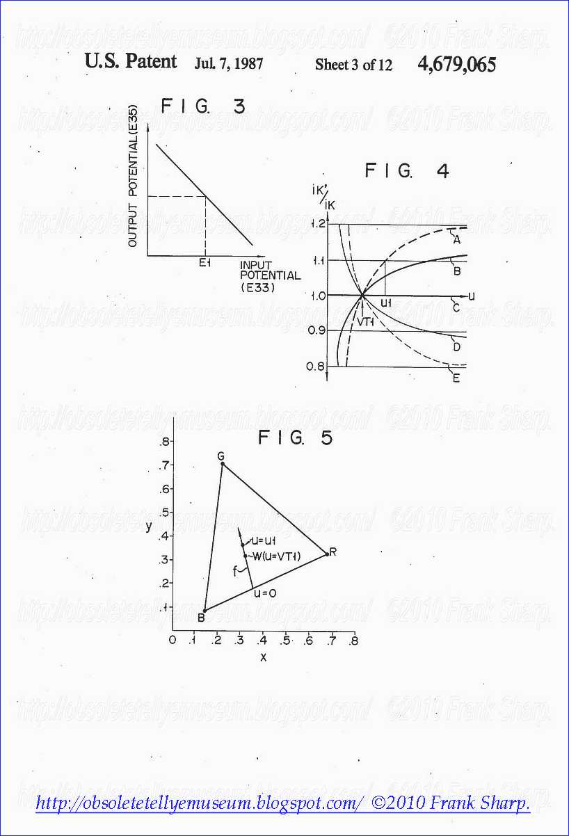
Comparator 35B has a
characteristic as shown in FIG. 3. When the reference potential applied
to the positive input (+) of comparator 35B is given to be E1 and the
input and output potentials of comparator 35B are respectively plotted
along the abscissa and ordinate, the output potential (E35B) decreases
as the input potential (E33B) increases.
Level correction circuit
18B has such an electrical characteristic that the output DC level of
signal E18B raises when DC control voltage E35B applied to control
terminal 24 increases, while the output DC level of E18B falls when E35B
decreases.
When the emission of cathode 21B is deteriorated (or a
certain drift in the operating point of associated circuitries occurs),
the corresponding cathode current I21B flowing into resistor 29 of
circuit 20B becomes small. The potential of signal E33B from sampling
circuit 33B is proportional to the magnitude of cathode current I21B
which is obtained at the period of reference insertion pulse E17A (FIG.
2D). Since the sampling is performed only during the period T1 of
reference insertion pulse E17A, the potential of signal E33B is
independent of the period of picture signal L. Thus, when the
deterioration of cathode emission occurs, the sampled output E33B is
decreased regardless of the presence of any picture signal L.

Comparator
35B compares reference potential E1 with the potential of sampled
output E33B. When a deterioration of the cathode emission occurs,
comparator 35B generates DC control voltage E35B which is increased in
accordance with the characteristic of FIG. 3. Then, the DC level of
signal E18B from level correction circuit 18B is increased, thereby
increasing the corresponding cathode current I21B.
On the
contrary, when the cathode current increases, operation opposite to the
operation described above is performed so as to decrease the
corresponding cathode current. The increase/decrease operation point of
the negative feedback control is stably converged to a point at which
the difference between the reference potential E1 and the sampled output
E33B becomes zero.
The
cathode emission correction operation for R and G components may be
performed in the same manner as that for the B component as described
above. When the negative feedback control circuit is arranged to set the
difference between the reference potential (E1) and the sampled output
(E33) to be zero while the initial reference white is properly adjusted,
the CRT biases for R, G, and B are automatically adjusted even if a
deterioration in the cathode emission of CRT or a drift in the operating
point of associated circuitries occurs. As a result, an automatic
correction is so performed that the reference white is always maintained
at a predetermined value.
The above operation will be exemplified using the circuit arrangement of the blue axis.
Assume
here that the first grid (control grid) of each electron gun of CRT 21
is circuit-grounded, the voltage potential at cathode 21B and the
current (I21B) flowing therethrough are respectively represented by uk
and ik, and the cutoff voltage of cathode 21B is given to be Vcut. Under
this assumption, cathode current ik is given as follows:
ik=(K/Vcut3/2)(Vcut-uk)r ( 1)
where K is a proportional constant,
and r is a specific constant of the CRT which is determined by the
characteristic of the electron gun. Specific constant r generally falls
within the range of 2.5 to 3.0.
When the input potential of
comparator 35B (i.e, the potential of output E33B from sampling circuit
33B) is denoted by ui and the resistance of resistor 29 is denoted by R,
input potential ui with respect to the circuit-ground is given to be:
ui=R.ik (2)
Further, when the potential of output E35B from
comparator 35B is assumed to be uA, the sensitivity of comparator 35B is
assumed to be A and the potential of reference potential source 36 is
assumed to be E1, the output potential uA is given as: uA=A(E1-ui) (3)
Accordingly,
it can be seen than comparator 35B is a difference amplifier with a
gain of A. When the potential of the signal component of reference
insertion pulse E17A supplied to level correction circuit 18B is assumed
to be VT1, the DC control sensitivity of circuit 18B is assumed to be B
and the potential of output E18B from circuit 18B is assumed to be uB,
the output potential uB is given as: uB=VT1+B.uA (4)
Furthermore,
when the collector potential of transistor 25 is assumed to be uc, the
resistance of resistor 27 is assumed to be R1, a resistance of resistor
26 is assumed to be R2 and the potential of voltage source Vcc is given
to be Vcc, the collector potential uc is given as follows:
uc=Vcc-(R2/R1)(uB-VBE1) (5)
where VBE1 denotes the base-emitter
voltage of transistor 25. Potential uc is applied to cathode 21B via the
base-emitter path of transistor 28.
A cathode potential uk at cathode 21B of CRT 21 is given as: uk=uc+VBE2 (6)
where VBE2 is the base-emitter voltage of transistor 28.
When
equations (2) to (5) are substituted into equation (6), the following
equation is obtained: ##EQU1## Equation (7) is substituted into equation
(1), so that ##EQU2## In equation (9), Vcut, Vcc, VBE1, VBE2 and R2/R1
are all constants. Accordingly, a circuit design for the configuration
of FIG. 1 enables the value of ΔV in equation (9) to be zero, that is,
ΔV=0 (9')
Then, equation (10) can be rewritten as: ik=(K/Vcut3/2)[(R2/R1){VT1+A.B(E1-R.ik)}]r ( 11)
The
cathode current ik, which nullifies the difference between input
potential ui and reference potential E1 at comparator 35B, is given to
be: ik=E1/R
The above equation is substituted into the right term of equation (11), so that ik=(K/Vcut3/2){(R2/R1)VT1}r ( 12)
Therefore, ik=E1R=(K/Vcut3/2){(R2/R1)VT1}r
The above equation may be rewritten as follows: E1=R.(K/Vcut3/2){(R2/R1)VT1}r ( 13)
When
circuit constants VT1, Vcc, E1 and so on are selected so that equation
(9') and E1 satisfy the relation of equation (13), the equation (8)
holds. A current (ik)T1 flowing during the sampling period T1 (FIG. 2D)
is stabilized at the following value: (ik)T1=E1/R=(Ik)T1 (14)
where Ik denotes the stabilized value of cathode current ik.
Meanwhile,
cutoff voltage Vcut of the electron gun of CRT 21 depends on the
spatial distance between the first and second grids. Variations in the
spatial distance during the fabrication of CRTs bring unfavorable
variations in cutoff voltage Vcut. When equation (13) is satisfied and a
variation in Vcut is given to be ΔVcut, ΔV of equation (9) is given as:
ΔV=Vcut+ΔVcut-{Vcc+VBE2+(R2/R1)VBE1} (15)
Upon the assumption of equation (9'), Vcut-{Vcc+VBE2+(R2/R1)VBE1}=0
so
that equation (15) is rewritten as ΔV=ΔVcut. Current (ik)T1 flowing
during the sampling period T1 is derived from equation (10) and it
satisfies the following equation: ##EQU3## In this case, if a current
error (which indicates a deviation from the target value of the cathode
current) is given to be (Δik)T1, a relation (ik)T1=(Ik)T1+(Δik)T1 is
obtained. According to equation (16), the right term of the above
relation is given as: ##EQU4## A relation E1-R.(ik)T1=0 is obtained from
equation (14), so that ##EQU5## if Vcut>>ΔVcut is satisfied and
equation (17) is given to be ΔVcut=(R2/R1){A.B.R(Δik)T1}
then (ik)T1+(Δik)T1=(K/Vcut3/2){(R2/R1)VT1}r
Therefore,
when the feedback control loop is arranged to satisfy the following
inequality: (R2/R1)A.B.R>>ΔVcut/(Δik)T1 (18)
the current flowing during the sampling period T1 is kept substantially constant.
The circuit arrangement of FIG. 1 described above has the following disadvantage.

Assume
that the voltage of a video signal is given to be u, that the cathode
current with cutoff voltage Vcut is given to be ik, that the cathode
current with cutoff voltage (Vcut+ΔVcut) is given to be ik', and that
the voltage of a video signal with cutoff voltage (Vcut+ΔVcut) is given
to be u+ΔVT1, then cathode currents ik and ik' are given as follows:
##EQU6## Therefore, the ratio of ik' to ik is given as: ##EQU7## It is
apparent that the reference white of a CRT can be fixed at a prescribed
constant value when the right term of equation (21) is constant.
However, it is very hard to keep the value of the right term of equation
(21) constant. This is because the right term of equation (21) cannot
be made constant unless a condition that ΔVcut=0 (and ΔVT1=0) is
satisfied. Only under this condition, does ik'/ik become constant. As
previously described, cutoff voltage Vcut varies during the fabrication
process of CRTs. It is almost impossible in practice to establish
ΔVcut=0. Thus, a color television receiver is subjected to the variation
ΔVcut, and the reference white cannot be kept constant throughout all
levels (black level to white level) of the video signal.
The
above problem of the prior art will be described with reference to the
graphs shown in FIGS. 4 and 5. Referring to FIG. 4, voltage u of the
video signal is plotted along the abscissa, and the change in ratio
ik'/ik in accordance with variation ΔVcut is plotted along the ordinate.
Each of curves A and B represents a change in ratio ik'/ik when
variation ΔVcut occurs in the negative side with respect to Vcut (here
the change of curve A in the negative side is greater than that of curve
B). Each of curves D and E represents a change in ratio ik'/ik when
variation Vcut occurs in the positive side with respect to Vcut (here
the change of curve E in the positive side is greater than that of curve
D). Curve C represents a desired ratio of ik'/ik obtained when ΔVcut=0.

As
is apparent from FIG. 4, ik'/ik=1 is obtained (i.e., ratio ik'/ik
becomes constant) only when ΔVcut=0. Ratio ik'/ik deviates from the
center value of 1.0 according to the changes in variation ΔVcut. For
instance, when the video signal voltage is set at ul in FIG. 4, ratio
ik'/ik =1.1 is obtained. When the video signal voltage is set at VT1
(i.e., when the video signal voltage is represented by the voltage of
reference insertion pulse E17A during the sampling period T1), ik'/ik=1
(constant) is obtained regardless of the change in ΔVcut. In other
words, when the voltage of the video signal is identical with VT1, the
reference white is fixed at a constant value. Otherwise, the reference
white deviates from a target value, except for ik'/ik=1.0.
The
deviation of the reference white will be discussed with reference to the
chromaticity diagram of FIG. 5. Line f in FIG. 5 indicats a deviation
in reference white of curve A in FIG. 4. Assume that R, G and B cathode
currents are given by equations (19) and (20) and are respectively
represented by iR, iG and iB which have a specific ratio
(iR:iG:iB=1:1:1) so as to obtain the reference white W. The reference
white is obtained only when the relation u=VT1 in FIG. 4 is established.
For instance, when u=u1 as shown in FIG. 4 is considered, the current
ratio is given to be: iR:iG:iB=1:1:1.1
Then, the current ratio changes. The deviation in the reference white due to this change is represented by line f in FIG. 5.
In
the course of the circuit design of a color television receiver, it is
almost impossible to ensure that the reference white comes to be
constant for all actual CRTs, unless the values of respective elements
such as voltages and resistances in the associated circuit arrangement
are carefully determined in consideration of variations in the
respective CRTs. Thus, the reference white is deviated in actual
commercial products due to changes in the video signal level.
SUMMARY OF THE INVENTION
It is accordingly the object of the present invention to provide a color television receiver which can rep

roduce
a picture with normal colors even if variations in the characteristic
of a color CRT are caused by variations in the fabrication process of
CRTs.
To achieve the above object, a color television receiver of
the invention is provided with special negative feedback loops for
automatically adjusting the amplitude of each cathode driving voltage of
R, G and B electron guns, so that the magnitude of each cathode current
of R, G and B electron guns is converged to a given value.
According
to the present invention, important and time-consuming reference white
adjustment in the fabrication process of color television receivers can
be simplified and stabilized by the operation of the special negative
feedback loops. Further, according to the negative feedback operation,
the adjusted reference white becomes insensitive to changes in the
cathode emission of CRT due to aging etc. From this, even after the
distribution of color television receivers to users, disadvantages
(e.g., degradation of color reproduction fidelity) due to deviations in
reference white can be automatically removed. Therefore, users can enjoy
a good picture with normal color for a long time, without periodical
reference white adjustment.
BRIEF DESCRIPTION OF THE DRAWINGS
FIG. 1 shows a prior art color television receiver having an automatic white control circuit;
FIGS. 2A to 2E are timing charts showing signals generated from the circuit components of FIG. 1;
FIG. 3 shows an operation characteristic of each comparator used in the circuit of FIG. 1;
FIG.
4 shows a graph explaining the problem of prior art, wherein the
voltage u of a video signal is plotted along the abscissa and the change
in ratio ik'/ik in accordance with the cutoff voltage variation ΔVcut
is plotted along the ordinate;
FIG. 5 shows a chromaticity
diagram explaining the problem of the prior art, wherein the line f
indicates a deviation in reference white of curve A in FIG. 4;
FIG. 6 shows a color television receiver according to an embodiment of the present invention;
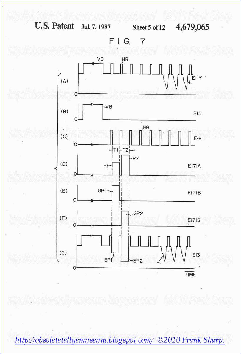
FIGS. 7A to 7G are timing charts explaining a typical operation of the embodiment shown in FIG. 6;
FIG. 8 shows an operation characteristic of each of comparators 53R, 53G and 53B used in the embodiment of FIG. 6;
FIG. 9 shows an operation characteristic of each of AGC amplifiers 58R, 58G and 58B used in the embodiment of FIG. 6;
FIGS. 10A to 10G are timing charts explaining another operation of the embodiment in FIG. 6;
FIGS. 11A to 11G are timing charts explaining still another operation of the embodiment in FIG. 6;
FIG. 12 shows a modification of the embodiment of FIG. 6;
FIG. 13 shows a circuit diagram of signal generator 171 used in FIG. 6;
FIG. 14 shows a circuit diagram of sampling circuit 33b used in FIG. 6;
FIG. 15 shows another circuit diagram of signal generator 171 used in FIG. 6;
FIG. 16 shows a waveform of signal E13 obtained when the circuit of FIG. 15 is employed; and
FIG.
17 shows a color television receiver according to another embodiment of
the present invention, which corresponds to the combination of the
disclosures of Japanese Patent Application Nos. 58-124607 and No.
58-124608 (both filed on July 11, 1983).
DETAILED DESCRIPTION OF THE PREFERRED EMBODIMENTS
A
color television receiver according to the present invention will be
described with reference to FIGS. 6 to 17. FIG. 6 is a block diagram of
the color television receiver according to the present invention. The
same reference numerals used in FIG. 6 denote the same parts as in FIG.
1, and a detailed description thereof will be omitted for the sake of
simplicity.
The following description will be given chiefly to
the key portion of the present invention. The function of a signal
generator 171 is different from that of signal generator 17 in FIG. 1.
The function of signal generator 171 will be described with reference to
FIGS. 7A to 7G. Signals shown in FIGS. 7A to 7C are the same as those
in FIGS. 2A to 2C, respectively. Signal generator 171 is arranged to
generate not only a first reference insertion pulse P1 during a period
T1 but also a second reference insertion pulse P2 during a period T2, as
shown in FIG. 7D. Second reference insertion pulse P2 is generated
within period T2 which is, e.g., delayed by 1 H from period T1 in the
horizontal blanking (HB) period. The amplitude of second reference
insertion pulse P2 is different from (larger than in this case) the
amplitude of first reference insertion pulse P1. When the amplitude of
pulse P1 corresponds to the condition that u=VT1 in FIG. 4, the
amplitude of pulse P2 corresponds to the condition that, e.g., u=u1.
According
to the present invention, the fact that the amplitude of P1 is
different from the amplitude of P2 is important. That is, when pulse P1
is used to determine the condition u=VT1, pulse P2 is used to converge
the value ik'/ik=1.1 on curve A in FIG. 4 to the value ik'/ik=1.0 on
curve C. A reference insertion pulse E171A containing first and second
reference insertion pulses P1 and P2 are supplied from an output
terminal 171A of generator 171A to mixer 13. A gate pulse E171B
containing first and second gate pulses GP1 and GP2 (FIGS. 7E and 7F) is
obtained from an output terminal 171B of generator 171. The generation
timing of gate pulses GP1 and GP2 is identical to or synchronized with
the generation timing of insertion pulses P1 and P2.
Sampling
circuits 33r, 33g and 33b respectively correspond to two sets of
sampling circuits 33R, 33G and 33B in FIG. 1. Each of circuits 33r, 33g
and 33b samples and holds the potential of corresponding signals E20R,
E20G and E20B according to gate pulse E171B from signal generator 171.
The sampled potentials of signals E20R, E20G and E20B respectively
correspond to the magnitudes of cathode currents I21R, I21G and I21B
during the durations of first and second insertion pulses P1 and P2.
Capacitors Cr1, Cg1 and Cb1 hold the sampled potentials during the
period T1 of pulse P1. Capacitors Cr2, Cg2 and Cb2 hold the sampled
potentials during the period T2 of pulse P2.
Sampled outputs
E33r, E33g and E33b obtained during the period of first reference
insertion pulse P1 are supplied to the respective negative inputs (-) of
comparators 35R, 35G and 35B. Each positive input (+) of comparators
35R, 35G and 35B receives a first reference potential E1 from a first
potential source 36. Outputs E35R, E35G and E35B from comparators 35R,
35G and 35B are respectively supplied to the control terminals 22, 23
and 24 of level correction circuits 18R, 18G and 18B.
Elements 18
to 20, 33 and 35 in FIG. 6 form DC negative feedback control loops for
controlling the cathode biases of R, G and B electron guns in CRT 21.
These control loops serve to equivalently shift each cutoff voltage Vcut
(DC) of the R, G and B electron guns to a specific value which is
determined by the reference potential E1 and which corresponds to the
point u=VT1 in FIG. 4.
Sampled outputs E330r, E330g and E330b
obtained during the period of second reference insertion pulse P2 are
supplied to the respective negative inputs (-) of comparators 53R, 53G
and 53B. Each positive input (+) of comparators 53R, 53G and 53B
receives a second reference potential E2 from a second potential source
54. Outputs E53R, E53G and E53B from comparators 53R, 53G and 53B are
respectively supplied to control input terminals 59, 60 and 61 of AGC
amplifiers 58R, 58G and 58B. AGC amplifiers 58R, 58G and 58B are
arranged between matrix circuits 12R, 12G and 12B and level correction
circuits 18R, 18G and 18B, respectively.
The input/output
characteristic of each of comparators 53R, 53G and 53B is shown in FIG.
8. In FIG. 8, the reference potential applied to the respective positive
inputs (+) of comparators 53R, 53G and 53B is given to be E2, the input
potential (E330) applied to the respective negative inputs (-) of these
comparators is plotted along the abscissa, and the output voltage (E53)
of these comparators is plotted along the ordinate. Thus, the output
voltage (E53) of these comparators decreases when the input voltage
(E330) increases, while the output voltage (E53) increases when the
input voltage (E330) decreases.

Each
of AGC amplifiers 58R, 58G and 58B has an input/output characteristic
as shown in FIG. 9. In FIG. 9, DC control voltages (E53) applied to
control input terminals 59, 60 and 61 of AGC amplifiers 58R, 58G and 58B
are plotted along the abscissa. The gain α of each of AGC amplifiers
58R, 58G and 58B is plotted along the ordinate. When signals E12R, E12G
and E12B are respectively inputted to AGC amplifiers 58R, 58G and 58B,
amplifiers 58R, 58G and 58B provide outputs E58R, E58G and E58B whose
voltages (amplitudes) respectively correspond not only to the amplitudes
of signals E12R, E12G and E12B but also to the potentials of DC control
voltages E53R, E53G and E53B. The higher the potential of control
voltage (E53) becomes, the higher the amplitude of output voltage (E58)
becomes. When the control voltage (E53) decreases, the output voltage
(E58) decreases.
Elements 58, 18 to 20, 33 and 53 in FIG. 6 form
AC negative feedback control loops for controlling the cathode driving
voltages of the R, G and B electron guns in CRT 21. These control loops
serve to converge each of cathode currents I21R, I21G and I21B (whose
magnitudes respectively correspond to the amplitudes (AC) of signals
E12R, E12G and E12B) of the R, G and B electron guns to a specific value
which is determined by the reference potential E2.
The operation
of the circuit shown in FIG. 6 will be described with reference to
FIGS. 7 to 9. FIG. 7A shows video signal E11Y appearing at output
terminal 11Y of television signal processing circuit 11; FIG. 7B shows
output E15 from vertical blanking pulse shaper 15; and FIG. 7C shows
output E16 from horizontal blanking pulse shaper 16. These signals E11Y,
E15 and E16 are similar to those in FIGS. 2A to 2C. FIG. 7D shows
reference insertion pulse E171A containing first and second reference
insertion pulses P1 and P2 which appear at terminal 171A of signal
generator 171. Pulses P1 and P2 are mixed in mixer 13 with video signal
E11Y of FIG. 7A. Mixer 13 outputs a composite video signal E13 as shown
in FIG. 7G. In FIG. 7G, the bottom potentials of signal components EP1
and EP2 respectively correspond to the top potentials of reference
insertion pulses P1 and P2. FIGS. 7D and 7E respectively show gate
pulses GP1 and GP2 obtained from terminal 171B of signal generator 171.

The
potentials of signals E20R, E20G and E20B corresponding to the cathode
currents I21R, I21G and I21B of CRT 21 during period T1 are sampled and
held in sampling circuits 33r, 33g and 33b. Sampled outputs E33r, E33g
and E33b are respectively supplied to comparators 35R, 35G and 35B and
are compared with first reference potential E1. Level correction
circuits 18R, 18G and 18B are controlled in accordance with the
potentials of comparison outputs E35R, E35G and E35B from comparators
35R, 35G and 35B. The DC negative feedback operation of elements 18, 19,
20, 33 and 35 in FIG. 6 is the same as that in FIG. 1. However,
according to the embodiment of the present invention, sampling circuits
33r, 33g and 33b are further operated during period T2 after period T1.
After period T1, comparators 53R, 53G and 53B and AGC amplifiers 58R,
58G and 58B are actuated. The AC negative feedback operation of elements
58, 18 to 20, 33 and 53 will be explained below using the circuit
elements of the blue axis.
As
previously described, the amplitude of second reference insertion pulse
P2 in period T2 is greater than that of first reference insertion pulse
P1 in period T1. Namely, the amplitude of second reference insertion
pulse P2 represents brighter white than the brightness of first
reference insertion pulse P1. The potential of signal E20B which
corresponds to cathode current I21B flowing during the period T2 is
sampled in sampling circuit 33b, and the sampled output E330b is
supplied to the negative input (-) of comparator 53B.
Reference
potential E2 applied to the positive input (+) of comparator 53B is
determined according to the following manner. Here, consideration will
be given to a case wherein an error as indicated by the said equation
(21) occurs, said equation (21) is: ##EQU8## The potential E2 of
potential source 54 is preset such that the potential at the negative
input (-) of comparator 53B, which is obtained when ik'/ik=1.0 is
established (i.e., when cutoff voltage Vcut is stabilized), becomes
equal to the potential at the positive input (+) of comparator 53B. From
this, if ik'/ik=1.0, no potential difference appears between the inputs
(+) and (-) of comparator 53B, and output E53B from comparator 53B
becomes constant. Then, the gain of AGC amplifier 58B is converged to
1.0, and output E58B from amplifier 58B is also kept constant. In other
words, the reference white is kept constant throughout all levels from
the black level to the white level.

When
variations in the fabrication process of CRT 21 cause variations in
cutoff voltage Vcut of electron guns so as to generate the deviation
ΔVcut (e.g., ik'/ik>1.0), cathode current I21B increases during
period T2 so that sampled output E330b from sampling circuit 33b is
increased. Then, sampled output E330b exceeds reference potential E2,
and output E53B from comparator 53B is decreased in accordance with the
characteristic as shown in FIG. 8. A decrease in output E53B from
comparator 53B is equal to a decrease in control input of AGC amplifier
58B. Thus, the input-to-output gain of AGC amplifier 58B becomes small
so that the drive voltage applied to cathode 21B of CRT 21 is decreased.
Therefore, ik'/ik is controlled to approach the stabilized value of
1.0.
However, if ik'/ik<1.0, sampled output E330b from
sampling circuit 33b is decreased, and output E53B from comparator 53B
is increased. The gain of AGC amplifier 58B is increased to increase the
drive voltage applied to cathode 21B of CRT 21. Even where
ik'/ik.perspectiveto.1.0, comparator 53B and AGC amplifier 58B carry out
the control operation to constantly maintain the relation ik'/ik=1.0.
The
above operation will be described using mathematical expressions. When
the cathode current flowing during the period T2 is given to be ik2,
input potential ui2 applied to sampling circuit 33b is given as follows:
ui2=R.ik2 (22)
When the sensitivity of comparator 53B and the
reference potential are given to be a and E2, respectively, output
potential uA2 from comparator 53B is given as follows: uA2=a(E2-ui2)
(23)

When
the control sensitivity of AGC amplifier 58B is given to be D, the
input voltage applied to level correction circuit 18B is given to be
VT2, the control sensitivity of level correction circuit 18B is given to
be B, the output potential from comparator 35B is given to be uA, then
an output potential uB2 from level correction circuit 18B is given as:
uB2=VT2(1+D.uA2)+B.uA (24)
(24)
Cathode currents ikl and ik2 flowing during periods T1 and T2 can be obtained from equations (1) to (10) as: ##EQU9##
When
circuit constants E2, VT2, etc. are selected such that reference
potential E2 satisfies the following equation (27) in the same manner as
in equation (13), equations (25) and (26) hold.
E2=R(K/Vcut3/2){(R2/R1)VT2}r (27)
When equations (25) and (26)
hold, currents (ik)T1 and (ik)T2 flowing during the sampling periods T1
and T2 are respectively stabilized at the following values:
(ik)T1=E1/R=(IK)T1 (28) (ik)T2=E2/R=(IK)T2 (29)
When cutoff
voltage Vcut varies due to deviations in the fabrication process of CRT
21, equation (20) can be rewritten in the embodiment as:
ik'={K/(Vcut+ΔVcut)3/2 }[(R2/R1).α.(u+VT1)]r (30)
where α denotes
the input-to-output gain of AGC amplifier 58B. Ratio ik'/ik is thus
given as follows: ik'/ik={Vcut/(Vcut+ΔVcut}3/2 ×[α.{(u+ΔVT1)/u}]r (31)
As
seen from the characteristic of FIG. 9, gain α of AGC amplifier 58B in
equation (31) is controlled by the potential of output E53B from
comparator 53B. Thus, a gain control is performed so as to obtain the
relation ik'=ik.
In
equation (31), ik'/ik=1.0 is obtained for u=VT1 and u=VT2. When VT1≠VT2
(e.g., VT2>VT1), the gain α can be calculated as follows:
α={(Vcut+ΔVcut)/Vcut}3/2r (32)
In this case, VT1 becomes zero, and equation (31) is given as: ik'/ik=1.0 (33)
The reference white is thus constant throughout all levels (from black level to white level) of the video signal.
Unlike
the current ratio of prior art given by equation (21), the current
ratio of the present invention which is given by equation (33) is
represented by line C in FIG. 4. Equation (33) is satisfied in all
levels of the video signal, and hence the reference white is constant.
This clearly demonstrates that no deviations from the reference white
point W in FIG. 5 occur.
In the above description, the operation
of the blue circuit is explained. The red and green circuits are
operated in the same manner as in the blue circuit, thereby
automatically controlling respective cathode driving voltages of R, G
and B electron guns in CRT 21.
Although the above description is
given to the case wherein the circuit of FIG. 6 operates according to
the timing charts of FIGS. 7A to 7G, the circuit of FIG. 6 may be
operated according to another way. For instance, as shown in FIGS. 10D
to 10G, the second insertion pulse P2 is generated before the generation
of first insertion pulse P1. Or, as shown in FIGS. 11D to 11G, the
amplitude of second insertion pulse P2 may be smaller than that of first
insertion pulse P1. Further, although not shown, the second insertion
pulse P2 may be separated by two or more horizontal pulses HB from the
first insertion pulse P1.
The locations of AGC amplifiers 58R,
58G and 58B are not limited to those shown in FIG. 6. So long as
substantially the same effect as in the embodiment of FIG. 6 is
obtained, the AGC amplifiers may be inserted in any positions in the
video signal transmission line. For instance, as shown in FIG. 12, AGC
amplifiers 58R, 58G and 58B may be respectively inserted between level
correction circuits 18R, 18G and 18B and CRT drivers 19R, 19G and 19B.

FIG.
13 shows a circuit example of signal generator 171 used in FIG. 6.
Horizontal blanking pulse HB of signal E16 is supplied via one input of
an AND gate 130 to the clock input CK of a D flip-flop 131. The D input
of flip-flop 131 receives its inverted Q output. The inverted Q output
from flip-flop 131 is supplied to the clock input CK of a D flip-flop
132 whose D input receives its inverted Q output. Each reset input R of
flip-flops 131 and 132 receives vertical blanking pulse VB of signal
E15. The inverted Q output from flip-flop 131 is supplied via an
inverter 133 to one input of a NAND gate 134. The other input of gate
134 receives the inverted Q output of filp-flop 132 via an inverter 135.
The NANDed output from gate 134 is supplied to the other input of AND
gate 130. The inverted Q output from flip-flop 131 and the output from
inverter 135 are respectively inputted to an AND gate 136. The output
from inverter 133 is used as the first gate pulse GP1 (FIGS. 7E, 10E or
11E). The ANDed output from gate 136 is used as the second gate pulse
GP2 (FIGS. 7F, 10F or 11F). Pulses GP1 and GP2 obtained from elements
133 and 136 constitute the gate pulse E171B.
The logical level of
gate pulse GP1 from inverter 133 controls the on/off of an analog
switch 137. When the level of pulse GP1 is high (FIG. 7E), switch 137 is
closed so that a first insertion potential source V1 provides the
high-level portion of first reference insertion pulse P1 (during T1 in
FIG. 7D). When the level of pulse GP1 is low, switch 137 is opened so
that pulse P1 disappears.
The logical level of gate pulse GP2
from AND gate 136 controls the on/off of an analog switch 138. When the
level of pulse GP2 is high (FIG. 7F), switch 138 is closed so that a
second insertion potential source V2 provides the high-level portion of
second reference insertion pulse P2 (during T2 in FIG. 7D). When the
level of pulse GP2 is low, switch 138 is opened so that pulse P2
disappears. Pulses P1 and P2 obtained from elements 137 and 138
constitute the reference insertion pulse E171A.
FIG. 14 shows a
circuit example of sampling circuit 33b used in FIG. 6. The circuit
configuration of 33r and 33g may be the same as that shown in FIG. 14.
Signal E20B representing cathode current I21B of the B electron gun in
CRT 21 is supplied via a buffer 140 to analog switches 141 and 142. The
on/off of switch 141 is controlled according to the logical level of
first gate pulse GP1. The on/off of switch 142 is controlled according
to the logical level of second gate pulse GP2.
When switch 141 is
closed by the high-level of pulse GP1, the potential of signal E20B,
which indicates the magnitude of cathode current I21B at period T1 (FIG.
7D), is applied to capacitor Cb1. Then, capacitor Cb1 is charged by a
voltage corresponding to the potential of signal E20B. The charged
voltage (sampled potential) at capacitor Cb1 is supplied to comparator
35B. When the level of pulse GP1 is low, switch 141 is opened so that
the charged voltage is held at capacitor Cb1.
When
switch 142 is closed by the high-level of pulse GP2, the potential of
signal E20B, which indicates the magnitude of cathode current I21B at
period T2 (FIG. 7D), is applied to capacitor Cb2. Then, capacitor Cb2 is
charged by a voltage corresponding to the potential of signal E20B. The
charged voltage (sampled potential) at capacitor Cb2 is supplied to
comparator 53B. When the level of pulse GP2 is low, switch 142 is opened
so that the charged voltage is held at capacitor Cb2.

FIG.
15 shows another circuit example of signal generator 171 used in FIG.
6. Horizontal blanking pulse HB of signal E16 is supplied via one input
of an AND gate 150 to the clock input CK of a D flip-flop 151. The D
input of flip-flop 151 receives its inverted Q output. The inverted Q
output from flip-flop 151 is supplied to the clock input CK of a D
flip-flop 152 whose D input receives its inverted Q output. Each reset
input R of flip-flops 151 and 152 receives vertical blanking pulse VB of
signal E15. The inverted Q output from flip-flop 152 is supplied to the
other input of AND gate 150. Signal E15 is supplied to the clock input
CK of a D flip-flop 153 whose D input receives its inverted Q output.
The inverted Q output from flip-flop 153 is supplied via an inverter 154
to one input of an AND gate 155. The other input of gate 155 receives
the Q output from flip-flop 151. The ANDed output from gate 155 is used
as the first gate pulse GP1. The inverted Q output from flip-flop 153
and the Q output from flip-flop 151 are inputted to an AND gate 156. The
ANDed output from gate 156 is used as the second gate pulse GP2. Pulses
GP1 and GP2 obtained from elements 155 and 156 constitute the gate
pulse E171B.
The logical level of gate pulse GP1 from AND gate
155 controls the on/off of an analog switch 157. When the level of pulse
GP1 is high, switch 157 is closed so that first insertion potential
source V1 provides the high-level portion of first reference insertion
pulse P1. When the level of pulse GP1 is low, switch 157 is opened so
that pulse P1 disappears.
The logical level of gate pulse GP2
from AND gate 156 controls the on/off of an analog switch 158. When the
level of pulse GP2 is high, switch 158 is closed so that second
insertion potential source V2 provides the high-level portion of second
reference insertion pulse P2. When the level of pulse GP2 is low, switch
158 is opened so that pulse P2 disappears. Pulses P1 and P2 obtained
from elements 157 and 158 constitute the reference insertion pulse
E171A.
FIG. 16 shows a waveform of signal E13 obtained when the
circuit of FIG. 15 is used with the configuration of FIG. 6. According
to the circuit of FIG. 13, signal components EP1 and EP2 in video signal
E13, which respectively correspond to first and second insertion pulses
P1 and P2, appear in one vertical scanning period. On the contrary,
according to the circuit of FIG. 15, only signal component EP1
corresponding to pulse P1 appears in a present vertical scanning period,
and only signal component EP2 corresponding to pulse P2 appears in the
next vertical scanning period. In other words, according to the circuit
of FIG. 15, the DC negative feedback loop of elements 18 to 20, 33 and
35 (FIG. 6) is activated based on the component EP1 in one vertical
scanning period, while the AC negative feedback loop of elements 58, 18
to 20, 33 and 53 (FIG. 6) is activated based on the component EP2 in the
next vertical scanning period.

FIG.
17 shows another embodiment of the present invention. According to the
embodiment of FIG. 17, application of excessive driving voltages to the
respective cathodes of CRT 21 immediately after the power-on of the
color television receiver can be prevented by the special circuit
elements (51X to 57X). Since the CRT is protected from intermittent
excessive driving at each time of power-on, the service life of the CRT
is extended. In addition, a stable picture is reproduced on the CRT
after the power-on of television receiver, thereby avoiding discomfort
to the viewers. The special circuit elements 51X to 57X are disclosed in
U.S. patent application No. 628,984 which was filed by the same
applicant as the present application. All disclosures of this Japanese
Patent Application No. 58-124607 are incorporated in the present
application.
 TDA8178S TV VERTICALDEFLECTION BOOSTER:
DESCRIPTION
Designedfor monitors and high performanceTVs,
the TDA8178Svertical deflection booster delivers
flyback voltages up to 90V.
The TDA8178S operates with supplies up to 42V
and provides up to 2App output current to drive to
yoke.
The TDA8178Sis offeredinHEPTAWATTpackage.
.FLYBACK GENERATOR
.THERMAL PROTECTION
.REFERENCE VOLTAGE.
TDA4950 TV EAST/WEST CORRECTION CIRCUIT:
DESCRIPTION
The T

DA4950 is a monolithic integrated circuit in a
8 pin minidip plastic package designed for use in
the east-west pin-cushion correction by driving a
diode modulator in TV and monitor applications.
.SQUARE GENERATOR FOR PARABOLIC
CURRENT
.EXTERNAL KEYSTONE ADJUSTMENT (sym-
metry of the parabola)
.INPUT FOR DYNAMIC FIELD CORRECTION
(beam current change)
.STATIC PICTURE WIDTH ADJUSTMENT
.PULSE-WIDTH MODULATOR
.FINAL STAGE D-CLASS WITH ENERGY RE-
DELIVERY
.PARASITIC
PARABOLA
SUPPRESSION,
DURING FLYBACK TIME OF THE VERTICAL
SAWTOOTH.
 TEA5101A - RGB HIGH VOLTAGE AMPLIFIER BASIC OPERATION AND APPLICATIONS:
GENERAL
The control of state-of-the-art color cathode ray
tubes requires high performance video amplifiers
which must satisfy both tube and video processor
characteristics.
When considering tube characteristics (see Fig-
ures 13 and 14),we note that a 130V cutoff voltage
is necessary to ensure a 5mA peak current.How-
ever 150V is a more appropriate value if the satu-
ration effect of the amplifier is to be taken into
account. As the dispersion range of the three guns
is ± 12%, the cutoff voltage should be adjustable
from 130V to 170V. The G2 voltage, from 700 to
1500V allows overall adjustment of the cutoff volt-
age for similar tube types.
A 200V supply voltage of the video amplifier is
necessary to achieve a correct blanking operation.
In addition, the video amplifier should have an
output saturation voltage drop lower than 15V, as
a drive voltage of 130V (resp. 115V) is necessary
to obtain a beam current of 4 mA for a gun which
has a cutoff point of 170V (resp. 130V).
Note : For all the calculations discussed above, the
G1 voltage is assumed to be 0V.
The video processor characteristics must also be
considered. As it generally delivers an output volt-
age of 2 to 3V, the video amplifier must provide a

closed loop DC g
ain of approximately 40.
The video amplifier dynamic performances must
also meet the requirements of good definition even
with RGB input signals (teletext,home computer...),
e.g. 1mm resolution on a 54cm CRT width scanned
in 52µs. Consequently, a slew rate better than
2000V/µs, i.e. rise and fall times lower than 50ns,
is needed. In addition, transition times must be the
same for the three channels so as to avoid coloured
transitions when displaying white characters. The
bandwidth of a video amplifier satisfying all these
requirements must be at least 7MHz for high level
signals and 10MHz for small signals.
One major feature of a video amplifier is its capa-
bility to monitor the beam current of the tube. This
function is necessary with modern video proces-
sors:
- for automatic adjustment of cutoff and also, where
required,video gain in order to improve the long
term performances by compensation for aging
effects through the life of the CRT. This adjust-
ment can be done either sequentially (gun after
gun) or in a parallel mode.
- for limiting the average beam current
A video amplifier
must also be flashover protected
and provide high crosstalk performances. Cros-
stalk effects are mainly caused by parasitic capaci-
tors and thus increase with the signal frequency. A
crosstalk level of -20dB at 5MHz is generally ac-
ceptable.
Table 1 summarizes the main features of a high
performance video amplifier.
Table 1 :
Main Features of a High Performance
Video Amplifier
Maximum Supply Voltage
220V
Output voltage swing "Average"
100V
Output voltage swing "Peak"
130V
Low level saturation (refered to VG1)
15V
Closed loop gain
40
Transition time
50ns
Large signal bandwidth
7MHz
Small signal bandwidth
10MHz
Beam current monitoring
Flash over protection
Crosstalk at 5MHz
-20dB
The SGS-THOMSON Microelectronics TEA5101A
is a high performance and large bandwidth 3 chan-
nel video amplifier which fulfills all the criteria dis-
cussed above. Designed in a 250V DMOS bipolar
technology, it operates with a 200V power supply
and can deliver 100V peak-to-peak output signals
with rise and fall times equal to 50ns.
The 5101A features a large signal bandwidth of
8MHz, which can be extended to 10MHz for small
signals (50 Vpp).
Each channel incorporates a PMOS transistor to
monitor the beam current. The circuit provides
internal protection against electrostatic discharges
and high voltage CRT discharges.
The best utilization of the TEA 5101A high perform-
ance features such as dynamic characteristics,
crosstalk,or flashover protection requires opti-
mized application implementation. This aspect will
be discussed in the fourth part of this document.
I.1 - Input Stage
The differential input stage consists of the transistor
T1 and T2 and the resistors R4,R5 and R6.
This stage is biased by a voltage source T3,R1,R2
and R3.
VB(T1) = (1 + R2
R3) x VB(T3) ≅ 3.8V
Each amplifier is biased by a separate voltage
source in order to reduce internal crosstalk. The
load of the input stage is composed of the transistor
T4 (cascode configuration) and the resistor R7. The
cascode configuration has been chosen so as to
reduce the Miller input capacitance. The voltage
gain of the input stage is fixed by R7 and the emitter
degenerati

on resistors R5,R6,and the T1,T2 internal
emitter resistances. The voltage gain is approxi-
mately 50dB.
Using a bipolar transistor T4 and a polysilicon re-
sistor R7 gives rise to a very low parasitic capaci-
tance at the output of this stage (about 1.5pF).
Hence the rise and fall times are about 50ns for a
100V peak-to-peak signal (between 50V and
150V).
I.2 - Output Stage
The output stage is a quasi-complementary class
B push-pull stage. This design ensures a symetrical
load of the first stage for both rising and falling
signals. The positive output stage is made of the
DMOS transistor T5,and the negative output stage
is made of the transistors PMOS T6 and DMOS T7.
The compound configuration T6-T7 is equivalent to
a single PMOS. A single PMOS transistor capable
of sinking the total current would have been too
large.
By virtue of the symetrical drive properties of the
output stage the rise and fall times are equal (50ns
for 100V DC output voltage).
I.3 - Beam Current Monitoring
This function is performed by the PMOS transistor
T8 in source follower configuration. The voltage on
the source (cathode output) follows the gate volt-
age (feedback output). The beam current is ab-
sorbed via T8 . On the drain of T8, this current will
be monitored by the videoprocessor.
I.4 - Protection Circuits
I.4.1 - MOS protection
Four zener diodes DZ(1-4) are connected between
gate and source of each MOS in order to prevent
the voltage from reaching the breakdown volt-
age.Hence the VGS voltage is internally limited to
± 15V.
I.4.2 - Protection against electrostatic dis-
charges
All the input/output pins of the TEA5101A are pro-
tected by the diodes D1-D7 which limit the overvol-
tage due to ESD.
I.4.3 - Flashover Protection
A high voltage and high current diode D5 is con-
nected between each output and the high voltage
power supply. During a flash, most of the current is
generally absorbed by the spark gap connected to
the CRT socket. The remaining current is absorbed
by the high voltage decoupling capacitor through
the diode D5. Hence the cathode voltage is
clamped to the supply voltage and the output volt-
age does not exceed this value.
I.1 - Voltage Amplifier
II.1.1 - Bias conditions Vin = Vref
The bias point is fixed by the feedback resistor
Rf,the bias resistor Rp, and by the internal refer-
ence voltage when Vin = Vref.
If VO is the output voltage (pin 9) :
VO = (1 + Rf
Rp) x Vref (1)
In this state T1 and T2 are conducting. A current
flows in R7 and T4 soT5 is on. The T5 drain current
is fed to the amplifier input through the feedback
resistor. The current in R7 is:
I(R7) = VDD − VO − VGS(T5)
R7
≅ VDD − VO
R7
and the current in T5 and Rf is :
I(T5) = VO − Vref
Rf
≅ VO
Rf
Thus the total current absorbed by each channel of
the TEA5101A is :
VDD
R7 + VO x (1
Rf − 1
R7)
The cathode (pin 7) output voltage is:
VO + VGS(T8) = VO
The beam current is absorbed by T8 and Rm. The
voltage developed across Rm by this current is fed
to the videoprocessor in order to monitor the beam
current.
II.1.2 - Dynamic operation
The TEA5101A operates as a closed loop amplifier,
with its voltage gain fixed by the resistors Rf and
Re.
Since the open loop gain A is not infinite, the resistor
Rp and the input impedance Rin must be consid-
ered.Hence the voltage gain is
G = − Rf
Re x
1
1 + 1
A (1 +
Rf
Rp ⁄ ⁄ Re ⁄ ⁄ Rin)
(2)
II.1.2.1 - Input voltage Vin < Vref (black picture)
In this case the current flowing in R7 and T1 de-
creases whilst the collector voltage of T4 and the
output voltage both increase. In the extreme case,
I(T1) = I(R7) = 0 and VO= VDD-VGS(T5)
In order to charge the tube capacitor the voltage is
fed to the cathode output in two ways:
- through the PMOS (with a VGS difference) for the
low frequency part
- through the capacitor C for the high frequency
part (output signal leading e
dge)
To correctly transmit the rising edge, the value of
the capacitor C must be high compared to CL.
With the current values used (C = 1nF,CL = 10pF),
the attenuation is very small (0.99)
II.1.2.2 - Input voltage Vin > Vref (white picture)
In this case,the current in R7 and T1 increases with
an accompanying drop of T4’s collector voltage until
T1 and T4 are saturated. At this point:
VO ≅ VC(T4) ≅ VCC
During a high to low transition (i.e. black-white
picture), the beam current is absorbed in two ways:
- through the capacitor C and the compound
PMOS T6-T7 for the high frequency part (falling
edge)
- through the PMOS T8 and the resistor Rm for the
low frequency part.
II.2 - Beam Current Monitoring
II.2.1 - Stationary state
The beam current monitoring is performed by the
PMOS T8 and the resistor Rm. When measuring low
currents (leakage, quasi cutoff),the Rm value is
generally high. When measuring high currents
(drive, average or peak beam current),Rm is gen-
erally bypassed by a lower impedance.
It should be noted that the current supplied by the
three guns flows through this resistor.Hence,with
too large a value for the resistor Rm,the cathode
voltage of the tubes will become too high for the
required operating current values.This is a funda-
mental difference between the TEA5101A and dis-
crete video amps. In discrete video amps, the
current monitoring transistor is a high voltage PNP
bipolar which may saturate. In this case the beam
current can flow through the transistor base and it

is no longer monitored by the video processor. This
effect does not occur with the TEA 5101A.
II.2.2 - Transient phase : low current measure-
ments
The cut-off adjustment sequence is generally as
follows:
In a first step, the cathode is set to a high voltage
(180V) in order to blank the CRT and to measure
the leakage current. In a second step, the tube is
slighly switched on to measure a very low current
(quasi cut-off current). This operation is performed
by setting the cathode voltage to about 150V and
adjusting it until the proper current is obtained. The
maximum time available to do this operation is
generally about 52µs.
Figure 3 shows the simplified diagram of the
TEA5101A output, the voltages during the different
steps,and the stationary state the system must
reach for correct adjustment.
I.1 - Voltage Amplifier
II.1.1 - Bias conditions Vin = Vref
The bias point is fixed by the feedback resistor
Rf,the bias resistor Rp, and by the internal refer-
ence voltage when Vin = Vref.
If VO is the output voltage (pin 9) :
VO = (1 + Rf
Rp) x Vref (1)
In this state T1 and T2 are conducting. A current
flows in R7 and T4 soT5 is on. The T5 drain current
is fed to the amplifier input through the feedback
resistor. The current in R7 is:
I(R7) = VDD − VO − VGS(T5)
R7
≅ VDD − VO
R7
and the current in T5 and Rf is :
I(T5) = VO − Vref
Rf
≅ VO
Rf
Thus the total current absorbed by each channel of
the TEA5101A is :
VDD
R7 + VO x (1
Rf − 1
R7)
The cathode (pin 7) output voltage is:
VO + VGS(T8) = VO
The beam current is absorbed by T8 and Rm. The
voltage developed across Rm by this current is fed
to the videoprocessor in order to monitor the beam
current.
II.1.2 - Dynamic operation
The TEA5101A operates as a closed loop amplifier,
with its voltage gain fixed by the resistors Rf and
Re.
Since the open loop gain A is not infinite, the resistor
Rp and the input impedance Rin must be consid-
ered.Hence the voltage gain is
G = − Rf
Re x
1
1 + 1
A (1 +
Rf
Rp ⁄ ⁄ Re ⁄ ⁄ Rin)
(2)
II.1.2.1 - Input voltage Vin < Vref (black picture)
In this case the current flowing in R7 and T1 de-
creases whilst the collector voltage of T4 and the
output voltage both increase. In the extreme case,
I(T1) = I(R7) = 0 and VO= VDD-VGS(T5)
In order to charge the tube capacitor the voltage is
fed to the cathode output in two ways:
- through the PMOS (with a VGS difference) for the
low frequency part
- through the capacitor C for the high frequency
part (output signal leading edge)
To correctly transmit the rising edge, the value of
the capacitor C must be high compared to CL.
With the current values used (C = 1nF,CL = 10pF),
the attenuation is very small (0.99)
II.1.2.2 - Input voltage Vin > Vref (white picture)
In this case,the current in R7 and T1 increases with
an accompanying drop of T4’s collector voltage until
T1 and T4 are saturated. At this point:
VO ≅ VC(T4) ≅ VCC
During a high to low transition (i.e. black-white
picture), the beam current is absorbed in two ways:
- through the capacitor C and the compound
PMOS T6-T7 for the high frequ
ency part (falling
edge)
- through the PMOS T8 and the resistor Rm for the
low frequency part.
II.2 - Beam Current Monitoring
II.2.1 - Stationary state
The beam current monitoring is performed by the
PMOS T8 and the resistor Rm. When measuring low
currents (leakage, quasi cutoff),the Rm value is
generally high. When measuring high currents
(drive, average or peak beam current),Rm is gen-
erally bypassed by a lower impedance.
It should be noted that the current supplied by the
three guns flows through this resistor.Hence,with
too large a value for the resistor Rm,the cathode
voltage of the tubes will become too high for the
required operating current values.This is a funda-
mental difference between the TEA5101A and dis-
crete video amps. In discrete video amps, the
current monitoring transistor is a high voltage PNP
bipolar which may saturate. In this case the beam
current can flow through the transistor base and it
is no longer monitored by the video processor. This
effect does not occur with the TEA 5101A.
II.2.2 - Transient phase : low current measure-
ments
The cut-off adjustment sequence is generally as
follows:
In a first step, the cathode is set to a high voltage
(180V) in order to blank the CRT and to measure
the leakage current. In a second step, the tube is
slighly switched on to measure a very low current
(quasi cut-off current). This operation is performed
by setting the cathode voltage to about 150V and
adjusting it until the proper current is obtained. The
maximum time available to do this operation is
generally about 52µs.
Figure 3 shows the simplified diagram of the
TEA5101A output, the voltages during the different
steps,and the stationary state the system must
reach for correct adjustment.
I.1 - Voltage Amplifier
II.1.1 - Bias conditions Vin = Vref
The bias point is fixed by the feedback resistor
Rf,the bias resistor Rp, and by the internal refer-
ence voltage when Vin = Vref.
If VO is the output voltage (pin 9) :
VO = (1 + Rf
Rp) x Vref (1)
In this state T1 and T2 are conducting. A current
flows in R7 and T4 soT5 is on. The T5 drain current
is fed to the amplifier input through the feedback
resistor. The current in R7 is:
I(R7) = VDD − VO − VGS(T5)
R7
≅ VDD − VO
R7
and the current in T5 and Rf is :
I(T5) = VO − Vref
Rf
≅ VO
Rf
Thus the total current absorbed by each channel of
the TEA5101A is :
VDD
R7 + VO x (1
Rf − 1
R7)
The cathode (pin 7) output voltage is:
VO + VGS(T8) = VO
The beam current is absorbed by T8 and Rm. The
voltage developed across Rm by this current is fed
to the videoprocessor in order to monitor the beam
current.
II.1.2 - Dynamic operation
The TEA5101A operates as a closed loop amplifier,
with its voltage gain fixed by the resistors Rf and
Re.
Since the open loop gain A is not infinite, the resistor
Rp and the input impedance Rin must be consid-
ered.Hence the voltage gain is
G = − Rf
Re x
1
1 + 1
A (1 +
Rf
Rp ⁄ ⁄ Re ⁄ ⁄ Rin)
(2)
II.1.2.1 - Input voltage Vin < Vref (black picture)
In this case the current flowing in R7 and T1 de-
creases whilst the collector voltage of T4 and the
output voltage both increase. In the extreme case,
I(T1) = I(R7) = 0 and VO= VDD-VGS(T5)
In order to charge the tube capacitor the voltage is
fed to the cathode output in two ways:
- through the PMOS (with a VGS difference) for the
low frequency part
- through the capacitor C for the high frequency
part (output signal leading edge)
To correctly transmit the rising edge, the value of
the capacitor C must be high compared to CL.
With the current values used (C = 1nF,CL = 10pF),
the attenuation is very small (0.99)
II.1.2.2 - Input voltage Vin > Vref (white picture)
In this case,the current in R7 and T1 increases with
an accompanying drop of T4’s collector voltage until
T1 and T4 are saturated. At this point:
VO ≅ VC(T4) ≅ VCC
During a high to low transition (i.e. black-white
picture), the beam current is absorbed in two ways:
- through the capacitor C and the compound
PMOS T6-T7 for the high frequency part (falling
edge)
- through the PMOS T8 and the resistor Rm for the
low frequency part.
II.2 - Beam Current Monitoring
II.2.1 - Stationary state
The beam current monitoring is performed by the
PMOS T8 and the resistor Rm. When measuring low
currents (leakage, quasi cutoff),the Rm value is
generally high. When measuring high currents
(drive, average or peak beam current),Rm is gen-
erally bypassed by a lower impedance.
It should be noted that the current supplied by the
three guns flows through this resistor.Hence,with
too large a value for the resistor Rm,the cathode
voltage of the tubes will become too high for the
required operating current values.This is a funda-
mental difference between the TEA5101A and dis-
crete video amps. In discrete video amps, the
current monitoring transistor is a high voltage PNP
bipolar which may saturate. In this case the beam
current can flow through the transistor base and it
is no longer monitored by the video processor. This
effect does not occur with the TEA 5101A.
II.2.2 - Transient phase : low current measure-
ments
The cut-off adjustment sequence is generally as
follows:
In a first step, the cathode is set to a high voltage
(180V) in order to blank the CRT and to measure
the leakage current. In a second step, the tube is
slighly switched on to measure a very low current
(quasi cut-off current). This operation is performed
by setting the cathode voltage to about 150V and
adjusting it until the proper current is obtained. The
maximum time available to do this operation is
generally about 52µs.
Figure 3 shows the simplified diagram of the
TEA5101A output, the voltages during the different
steps,and the stationary state the system must
reach for correct adjustment.
During the blanking phase, the tube is switched off,
the PMOS is switched off and its VGS voltage is
equal to the pinch-off voltage (about 1.5V). The
voltages at the different nodes are shown in figure
3 (V(9) = 180V, V(k) = 181.5V). The falling edge of
the cutoff pulse is instantaneously transmitted by
the capacitor C. When the stationary state is
reached, the cathode voltage will be 152.5V if the
voltage on pin 9 is 150V, as the VGS voltage of the
conducting PMOS is about 2.5V.
We can see that the voltage
on C must increase by
an amount of ∆Vc = 1V. This charge is furnished by
the tube capacitor which is discharged by an
amount of ∆VCL = 29V with a time constant equal
to R x CL (10 ns). By considering the energy
balance, we can calculate the maximum charge
∆Vmax that CL can furnished to C
∆Vmax = √CL
C x ∆VCL ≅ 3V
Since this voltage is greater than ∆VC, the capacitor
C can be charged and the stationary state is
reached without any contribution being required
from the tube current,i.e. the whole tube current
can flow through the PMOS and the adjustment can
be performed correctly.
Considering higher voltage and beam current
swings, the margin is greater because:
- the voltage swing across the tube capacitor is
greater
- the tube current is higher and the picture is not
disturbed even if part of the beam current is used
to charge the capacitor C.
TELEFUNKEN SR285 (ICC8) CHASSIS THOMSON ICC8 ST6395B1/XZJ ICC8-B33.
GENERAL DESCRIPTION
The ST639xmicrocontrollers aremembers of the 8-
bit HCMOS ST638x family, a series of devices specially
orientedto TVapplications.DifferentROMsize
and peripheral configurations are available to give

the maximum application and cost flexibility. All
ST639xmembers are based on a building block approach:
a common core is surroundedbya combination
of on-chip peripherals (macrocells) available
from a standard library. These peripherals are designed
with the same Core technology providing full
compatibility and short design time. Many of these
macrocells are specially dedicated to TV applications.
Themacrocells of the ST639x family are: two
Timer peripherals each including an 8-bit counter
with a 7-bit software programmable prescaler
(Timer), a digital hardware activated watchdog
function(DHWD), a 14-bit voltage synthesis tuning
peripheral, a Serial Peripheral Interface (SPI), up
to six 6-bit PWMD/A converters, an AFC A/D converter
with 0.5V resolution, an on-screen display
(OSD) with 15 characters per line and 128 characters
(in two banks each of 64 characters). In addition
the following memory resources are available:
program ROM (up to 20K), data RAM (256 bytes),
EEPROM(up to 384 bytes). Refer to pin configurations
figures and to ST639x device summary (Table
1) for the definition of ST639x family members
and a summary of differences among the different
types.
4.5 to 6V supply operating range
8MHz Maximum Clock Frequency
User Program ROM: Up to 20140 bytes
Reserved TestROM:Up to 340 bytes
Data ROM: User selectable size
Data RAM: 256 bytes
Data EEPROM: Up to 384 bytes
42-Pin Shrink Dual in Line Plastic Package
Up to 23 software programmable general purpose
Inputs/Outputs, including 2 direct LED
driving Outputs
Two Timers each including an 8-bit counter with
a 7-bit programmable prescaler
Digital Watchdog Function
Serial Peripheral Interface (SPI) supporting
S-BUS/ I2C BUS and standard serial protocols
SPI for external frequency synthesis tuning
Up to Six 6-Bit PWMD/A Converters
AFC A/D converter with 0.5V resolution
Five interrupt vectors (IRIN/NMI, Timer 1 & 2,
VSYNC,PWR INT.)
On-chip clock oscillator
5 Lines by 15 Characters On-Screen Display
Generator with 128 Characters
All ROM types are supported by pin-to-pin
EPROMand OTP versions.
The development tool of the ST639x microcontrollers
consists of the ST638x-EMUemulation
and development system to be connected via a
standard RS232 serial line to an MS-DOS Personal
Computer.
TELEFUNKEN SR285 (ICC8) CHASSIS THOMSON ICC8 STEREO VIF SOUND UNIT AM-FM 8015 00 1004 1140

SIEMENS TDA6612
PHILIPS TDA9821
SIEMENS TDA6612-2
TV-Stereo-Sound
Features
The TDA 6612-2 represents a complete TV-stereo system
controlled by the I2C Bus according to German TV-Stereo
standard.
- All functions inclusive matrix adjustment are I2C Bus
controlled
- Inputs for AM sound or NICAM
- SCART-interface
- Independent headphones
- Universal clock generation circuit build-in
- Clipping detector build-in
- Volume control
- High signal-to-noise ratio
- Extremely low total harmonic distortions
- High security for the detection of the identification
signals because of the digital interference suppression
and the very narrow bandwidth.
The IC is divided into three functional blocks
1 Stereo Sound Processing with High Performance (exceeds DIN 45500; suitable for
NICAM and CD)
a) Matrix for G-standard with crosstalk compensation controlled via the I2C Bus
b) Additional single channel AF input (for e.g. AF signal according to L-standard)
c) Stereo SC
ART interface according to FTZ-official specification
d) Stereo loudspeaker signal section with Ch1/Ch2 switch, bass/treble control,
quasi stereo/stereo base width expansion and separate loudspeaker volume
control for left and right (balance)
e) Separate stereo head phone signal section with Ch1/Ch2 switch and volume
control
2 TV-Sound Identification Signal Decoder Consisting of:
a) Active pilot signal filter
b) Phase independent rectifier with very narrow bandwidth for evaluation of the
identification signal
c) Digital integrator to reduce interferences by noise
d) Multiplexer for cyclical switch over between "stereo" or "dual" evaluation
e) Reference signal generation with externally synchronized PLL
• synchronization with external H-sync pulse or 62.5-kHz clock
• build-in crystal oscillator and external 4-MHz crystal
• external 4-MHz (or 1-MHz) clock signal
3 Control Section for:
a) I2C Bus interface with listen/talk function
b) Control of the complete AF-sound signal detector
c) Read access to the clipping detector
d) Control of the identification signal decoder
e) Reading of the status of the identification signal decoder
f) Test modes.
Circuit Des
cription
Signal Section
The audio signal processing in the matrix and the switch-over for multi channel TV-sound signals
according to the two carrier system used in Germany takes place in the matrix and switching sec-
tions. Crosstalk compensation is carried out in the sound 1 input stage. The crosstalk compensation
range has an adjustment range of ± 3 dB with a step width of 0.2 dB. In addition to the two inputs
for the demodulated sound carrier a two channel SCART-input and an additional mono input (e.g.
for demodulated L-standard sound) are provided. The two AF (pin 1 and pin 2) inputs can be by-
passed internally in such a way that decoded stereo sound of other audio systems (NICAM) can be
processed. The switching section includes also the SCART-output with the possibility to select the
sound 1 or 2 during the "dual" mode. The Ch1/Ch2-switches for the loudspeaker and headphone
outputs are independently switchable.
In the signal path for the volume control unit output there is the Ch1/Ch2-switch followed by two dif-
ferent volume control units. The first has a control range from 0 to – 15 dB with a step width of 1.25
dB. In conjunction with the main volume control after bass and treble control a high immunity against
overdriving the output stage is reached. The first volume control is used as a "pre-stage" of the main
volume control in conjuntion with the clipping detector. This section is followed by a switchable quasi
stereo stage which provides a stereophonic audio effect with mono signals due to a 180˚ phase shift
at medium frequencies (about 1 kHz) in one channel. The following bass control has a control range
of +15/–12 dB with a step width of 3 dB. The cut-off frequency for each channel is set with an ex-
ternal capacitor. The implemented switchable circuit for stereo base width expansion provides a
three dimensional aural reception. This is
realized with a 50% frequency dependent crosstalk with
opposite phase of the signal between both channels. The circuit operates with the same cut-off fre-
quency as the bass control, but the function is widely independent. The treble control has a step
width of 3 dB with an control range of +/–12 dB. The cut-off frequency of the treble control is derived
from one capacitor for each channel. The loudspeaker signal path is terminated with the loudspea-
ker control, independently adjustable for left and right. With 57 steps of 1.25 dB the adjustment ran-
ge is 70 dB, where step 57 activates the "MUTE" function. Functions such as "balance" or "loud-
ness" are realized by software and adjustment of the appropriate tone and volume controls. In the
volume control unit there is a clipping detector. The status of the clipping detector can be evaluated
via the I2C Bus. Therefore it is possible to implement an automatic volume control using the clipping
detector and software implemented into the controller.
After every evaluation the clipping bit is reset. Therefore after a read access to the clipping bit a new
evaluation of the clipping detector status is possible.
The signal path for the headphon

es contains a volume control after the Ch1/Ch2-switch with a com-
mon adjustment for left and right. Thirty two steps of 2 dB give an adjustment range of 62 dB (31 x
2 dB = 62 dB, the 32nd step is MUTE).
Identification Signal Decoder
The input of the identification signal decoder consists of an op-amp for the pilot signal with its side
bands. An external LC-circuit is used. The signal is then passed to a phase independent active
band-pass filter with a very narrow bandwidth (adjustable externally). This filter detects whether the
lower side band of the pilot carrier, which is modulated with the identification signal, is present.
THE center frequency of the filter is switched between "dual" and "stereo" by a multiplexer. The
multiplexing frequency is adjustable by software. If a side band is detected, the multiplexer stops.
The interferences on the first "detected" criterion are suppressed by a digital integrator with a
following comparator and can be read out via I2C Bus (talk mode) as the "stereo" or "dual" mode.
The control of the corresponding signal can be either directly internally or through the µC. All the
necessary clock signal are derived from a fast setting PLL which is synchronized by a reference
frequency. This reference frequency must be sufficiently close to the horizontal frequency, but a
rigid phase coupling is not required. Therefore, alternatively the use of a crystal controlled 62.5-
kHz frequency commonly found in PLL-tuning systems is possible. A further alternative for the clock
signal generation is a b
uild-in crystal oscillator with an external 4-MHz crystal or the use an external
1- or 4-MHz clock frequency.
Control Section
All functions are controlled via an I2C Bus interface with "listen" / "talk" functions. The data bytes
currently used are stored in a block of latches.
The telegram structure is formed in the following manner:
start condition - chip address - any number of bytes - stop condition
The following conditions apply to the data bytes:
Before the actual data byte (with the adjustment information), always an I2C Bus sub-address byte
has to be transmitted. The I2C Bus interface however is interpreting this sub-address byte as a data
byte.
Example: The headphone volume is to be increased in a number of steps.
Within a telegram (i.
e. without a new start condition) any different sub-addresses can be accessed.
The changeover between "listen" and "talk" access to the IC however must always occur using the
following sequence: stop condition - start condition - chip address. Before each read access always
a start condition and chip address (talk) must be transmitted. The data to be read out are then
loaded into the I2C Bus interface and can be transferred to the µC.
Right
Wrong
Start condition
Chip address 84 (Hex)
Sub-addr. vol. HP 03 (Hex)
Vol. step 8 08 (Hex)
Sub-addr. vol. HP 03 (Hex)
Vol. step 9 09 (Hex)
Sub-addr. vol. HP 03 (Hex)
Vol. step 10 0A (Hex)
Stop condition
Start condition
Chip address 84 (Hex)
Sub-addr. vol. HP 03 (Hex)
Vol. step 8 08 (Hex)
Vol. step 9 09 (Hex)
Vol. step 10 0A (Hex)
Stop condition.
PHILIPS TDA9812 Multistandard VIF-PLL and FM-PLL/AM demodulator:
GENERAL DESCRIPTIO
N
The TDA9812/T is an integrated circuit for multistandard
vision IF signal processing and AM and FM sound
demodulation in TV and VTR sets.
FEATURES
• 5 V positive supply voltage
• Gain controlled wide band VIF-amplifier (AC-coupled)
• True synchronous demodulation with active carrier
regeneration (very linear demodulation, good
intermodulation figures, reduced harmonics, excellent
pulse response)
• Gated phase detector for L/L accent standard
• VCO frequency switchable between L and L accent
(alignment external) picture carrier frequency
• Separate video amplifier for sound trap buffering with
high video bandwidth
• VIF AGC detector for gain control, operating as peak
sync detector for B/G (optional external AGC) and peak
white detector for L; signal controlled reaction time for L
• Tuner AGC with adjustable Take Over Point (TOP)
• AFC detector without extra reference circuit
• AC-coupled limiter amplifier for sound intercarrier signal
• Alignment-free FM-PLL demodulator with high linearity,
switchable de-emphasis for FM
• AM-SIF AGC detector for gain controlled SIF amplifier
• AM demodulator without extra reference circuit
• Stabilizer circuit for ripple rejection and to achieve
constant output signals.
FUNCTIONAL DESCRIPTION
Vision IF amplifier
The vision IF amplifier consists of three AC-coupled
differential amplifier stages. Each differential stage
comprises a feedback network controlled by emitter
degeneration.
Tuner and VIF AGC
The AGC capacitor voltage is transferred to an internal IF
control signal, and is fed to the tuner AGC to generate the
tuner AGC output cur
rent (open-collector output). The
tuner AGC take-over point can be adjusted. This allows the
tuner and the SWIF filter to be matched to achieve the
optimum IF input level.
The AGC detector charges/discharges the AGC capacitor
to the required voltage for setting of VIF and tuner gain in
order to keep the video signal at a constant level.
Therefore for negative video modulation the sync level and
for positive video modulation the peak white level of the
video signal is detected. In order to reduce the reaction
time for positive modulation, where a very large time
constant is needed, an additional level detector increases
the discharging current of the AGC capacitor (fast mode)
in the event of a decreasing VIF amplitude step. The
additional level information is given by the black-level
detector voltage.
Frequency-Phase detector (FPLL)
The VIF-amplifier output signal is fed into a frequency
detector and into a phase detector via a limiting amplifier.
During acquisition the frequency detector produces a DC
current proportional to the frequency difference between
the input and the VCO signal. After frequency lock-in the
phase detector produces a DC current proportional to the
phase difference between the VCO and the input signal.
The DC current of either frequency detector or phase
detector is converted into a DC voltage via the loop filter,
which controls the VCO frequency. In the event of positive
modulated signals the phase detector is gated by
composite sync in order to avoid
signal distortion for
overmodulated VIF signals.
VCO, travelling wave divider and AFC
The VCO operates with a resonance circuit (with L and C
in parallel) at double the PC frequency. The VCO is
controlled by two integrated variable capacitors. The
control voltage required to tune the VCO from its free-
running frequency to actually double the PC frequency is
generated by the Frequency-Phase detector and fed via
the loop filter to the first variable capacitor (FPLL). This
control voltage is amplified and additionally converted into
a current which represents the AFC output signal. The
VCO centre frequency can be decreased (required for
L/L accent standard) by activating an additional internal
capacitor. This is achieved by using the L/L accent switch.
In this event the second variable capacitor can be
controlled by a variable resistor at the L/L accent switch for
setting the VCO centre frequency to the required
L/L accent value. At centre frequency the AFC output
current is equal to zero.
The oscillator signal is divided-by-two with a Travelling
Wave Divider (TWD) which generates two differential
output signals with a 90 degree phase difference
independent of the frequency.
Video demodulator and amplifier
The video demodulator is realized by a multiplier which is
designed for lo
w distortion and large bandwidth. The vision
IF input signal is multiplied with the ‘in phase’ signal of the
travelling wave divider output. In the demodulator stage
the video signal polarity can be switched in accordance
with the TV standard.
The demodulator output signal is fed via an integrated
low-pass filter for attenuation of the carrier harmonics to
the video amplifier. The video amplifier is realized by an
operational amplifier with internal feedback and high
bandwidth. A low-pass filter is integrated to achieve an
attenuation of the carrier harmonics for B/G and
L standard. The standard dependent level shift in this
stage delivers the same sync level for positive and
negative modulation. The video output signal is 1 V (p-p)
for nominal vision IF modulation.
Video buffer
For an easy adaption of the sound traps an operational
amplifier with internal feedback is used in the event of B/G
and L standard. This amplifier is featured with a high
bandwidth and 7 dB gain. The input impedance is adapted
for operating in combination with ceramic sound traps. The
output stage delivers a nominal 2 V (p-p) positive video
signal. Noise clipping is provided.
SIF amplifier and AGC for AM sound
The sound IF amplifier consists of two AC-coupled
differential amplifier stages. Each differential stage
comprises a controlled feedback network provided by
emitter degeneration.
The SIF AGC detector is related to the SIF input signals
(average level of AM carrier) and controls the SIF amplifier
to provide a constant SIF signal to the AM demodulator.
The SIF AGC reaction time is set to ‘slow’ for nominal
video conditions. But with a decreasing VIF amplitude step
the SIF AGC is set to ‘fast’ mode controlled by the VIF
AGC detector.
Intercarrier mixer
The intercarrier mixer is realized by a multiplier. The VIF
amplifier output signal is fed to the intercarrier mixer and
converted to intercarrier frequency by the regenerated
picture carrier (VCO). The mixer output signal is fed via a
high-pass for attenuation of the video signal components.
AM demodulator
The AM demodulator is realized by a multiplier. The
modulated SIF amplifier output signal is multiplied in
phase with the limited (AM is removed) SIF amplifier
output signal. The demodulator output signal is fed via an
integrated low-pass filter for attenuation of the carrier
harmonics to the AF amplifier.
FM detector
The FM detector consists of a limiter, an FM-PLL and an
AF amplifier. The limiter provides the amplification and
limitation of the FM sound intercarrier signal before
demodulation. The result is high sensitivity and AM
suppression. The amplifier consists of 7 stages which are
internally AC-coupled in order to minimize the DC offset
and to save pins for DC decoupling.
The FM-PLL consists of an integrated relaxation oscillator,
an integrated loop filter and a phase detector. The
oscillator is locked to the FM intercarrier signal, output
from the limiter. As a result of locking, the oscillator
frequency tracks with the modulation of the input signal
and the oscillator control voltage is superimposed by the
AF voltage. The FM-PLL operates as an FM-demodulator
The AF amplifier consists of two parts:
• The AF preamplifier for FM sound is an operational
amplifier with internal feedback, high gain and high
common mode rejection. The AF voltage from the PLL
demodulator, by principle a small output signal, is
amplified by approximately 33 dB. The low-pass
characteristic of the amplifier reduces the harmonics of
the intercarrier signal at the sound output terminal, at
which the de-emphasis network for FM sound is applied.
An additional DC control circuit is implemented to keep
the DC level constant, independent of process spread.
• The AF output
amplifier (10 dB) provides the required
output level by a rail-to-rail output stage. This amplifier
makes use of an input selector for switching to AM, FM
de-emphasis or mute state, controlled by the standard
switching voltage and the mute switching voltage.
Internal voltage stabilizer and1⁄2VP-reference
The bandgap circuit internally generates a voltage of
approximately 1.25 V, independent of supply voltage and
temperature. A voltage regulator circuit, connected to this
voltage, produces a constant voltage of 3.6 V which is
used as an internal reference voltage.
For all audio output signals the constant reference voltage
cannot be used because large output signals are required.
Therefore these signals refer to half the supply voltage to
achieve a symmetrical headroom, especially for the
rail-to-rail output stage. For ripple and noise attenuation
the1⁄2VP voltage has to be filtered via a low-pass filter by
using an external capacitor together with an integrated
resistor (fg= 5 Hz). For a fast setting to 1⁄2VP an internal
start-up circuit is added.
TELEFUNKEN SR285 (ICC8) CHASSIS THOMSON ICC8 Television startup current regulation:
A
television receiver has a switched mode power supply controller, which
may be deflection synchronized, which produces pulses in a power
transformer. To power the controller during startup, before the internal
power supply has started, a storage capacitor on the p
ower supply
input of the controller is coupled through a current limiting
resistance to a rectified voltage from the AC mains so as to charge the
storage capacitor during first polarity phases of the AC mains. The
current limiting resistance includes a positive temperature coefficient
(PTC) element which increases its impedance as it heats, to reduce
power dissipation after initial connection of the television receiver
to AC mains. In addition, a diode is coupled in a current path to the
storage capacitor to charge the capacitor to the same polarity as
during opposite polarity phases of the AC mains. The two paths for
charging the capacitor allow a relatively smaller value for the current
limiting resistance, which remains coupled to the storage capacitor,
and provides sufficient power to the controller without undue power
dissipation over a wide range of power mains voltages.
1.
A television apparatus having a degaussing coil for demagnetizing
metal portions of a cathode ray tube, said degaussing coil being
energized from an AC source, and coupled to a first temperature
dependent impedance for controlling the current passing in said
degaussing coil, said first temperature dependent impedance being
thermally coupled to a second temperature dependent impedance for
heating said first temperature dependent impedance, a power supply
including a capacitance for energizing a load circuit, and means for
charging said capacitance through said second temperature dependent
impedance, said capacitor being additionally charged through a path
including a rectifier, said path being independent of said first and
second temperature dependent impedances.
Description:
The invention relates to the startup of a switched mode power supply in a television receiver.
In
a television receiver having a switched mode power supply (SMPS),
which may be deflection synchronized, the primary winding of a power
transformer is energized by a pulse width modulated signal. The
secondary windings of the transformer energize DC power supplies which
provide power to operational loads, including the SMPS controller. In
the start up interval, immediately after switching the television
receiver on, it is necessary to initiate generation of power through the
power transformer in order to begin operation. The SMPS controller
itself may be powered from a storage capacitor which is initially
charged by rectified AC mains current through a current limiting
resistor. The capacitor charges initially when the television receiver
is connected to the AC mains (i.e., plugged in) and remains charged for
energizing the controller whenever the television receiver is either in
the standby mode or run mode of operation.

The current
limiting resistor dissipates power as long as the television receiver
is coupled to the AC mains. However, for purposes other than providing
power during the startup interval, this power is wasted. The current
limiting resistor can have a high resistance to reduce power
dissipation, but a higher resistance results in a reduced current
supply for operation of the controller, and slower charging of the
storage capacitor. It is necessary to reconcile the need for current to
the controller in the startup interval with the need to reduce power
dissipation in the current limiting resistor at all other times.
In
designing a switched mode power supply, it is advantageous to provide a
single circuit that is operable over a range of different mains
voltages. The standard mains voltages for the US and for Europe, for
example, differ substantially. A circuit which is optimal at one mains
voltage may include current limiting elements which produce excessive
power dissipation, inadequate current supply or other adverse effects
when operated at a different mains voltage.
Apart from
circuitry associated with startup of operational power, television
receivers are typically provided with degaussing coils which
demagnetize ferromagnetic parts of the picture tube to improve color
purity. The degaussing coils may be coupled to the AC mains through one
or more variable impedance elements that progressively reduce the
current applied to the degaussing coils over a degaussing interval
following the connection of the television to the AC mains. The current
limiting elements can be positive or negative temperature coefficient
resistors, also known as thermistors. In one technique, a first
temperature dependent resistor having a positive coefficient is coupled
to the AC mains in series with the degaussing coil. A second
temperature dependent resistor having
a positive coefficient is coupled
across the AC mains, the two temperature dependent resistors being
thermally coupled to each other such that each heats the other. As the
resistances of the elements change with heating, current through the
degaussing coil falls off to a minimum level which does not
substantially affect color purity.
In an inventive arrangement,
temperature dependent elements may be used in connection with the
charging of a storage capacitor for the supply voltage of a switched
mode power supply controller, as a means to limit power dissipation. In
carrying out an inventive feature, operation of a television receiver
during startup is optimized by coupling the degaussing circuitry with
the current limiting means for charging the storage capacitor that
provides power to the switched mode power supply controller. A circuit
for degaussing and current limited startup supply, optimized over a
wide range of power mains voltages may thus be achieved.
In
accordance with an aspect of the invention, a television apparatus has a
degaussing coil for demagnetizing metal portions of a cathode ray
tube. The degaussing coil is energized from an AC source, and coupled
to a first temperature dependent impedance for controlling the current
passing in the degaussing coil. The first temperature dependent
impedance is thermally coupled to a second temperature dependent
impedance for heating the first temperature dependent impedance. A
power supply includes a capacitance for energizing a load circuit. The
capacitance is charged through the second temperature dependent
impedance.
In accordance with another aspect of the invention, a
television apparatus having a power supply includes a capacitance for
energizing a load circuit and a source for charging the capacitance. A
start-up circuit comprises a source of AC current. A first polarity of
the AC current is passed to charge the capacitance, and an opposite
polarity of the AC current is passed through a temperature sensitive
impedance via a path independent of the path of the first polarity of
the AC current, to charge the capacitor in the same direction as said
first polarity of said AC current.
FIG. 1 is a schematic circuit diagram of part of a television receiver incorporating a startup current supply accordin

g to the invention;
FIG.
2 is a graph of voltage vs. time in the circuit shown in FIG. 1 at the
junction of current limiting resistor R2 and diode D7 with respect to
ground; and
FIG. 3 is a graph of voltage vs. time at the same point as in FIG. 2, but at a higher mains voltage.
In
a television receiver as shown in FIG. 1, power for the operational
loads is derived from a power transformer X1 when driven by a switched
mode power supply controller 60 and a power output transistor Q1. In
some applications, the power transformer may be a horizontal output
transformer. The various operational loads are coupled to secondary
windings of transformer X1, one operational load RL being shown as
coupled to a secondary winding 34. A diode D5 and a filter capacitor C3
are coupled to the secondary winding 34 for supply of regulated DC
voltage to load RL. Additional secondary windings typically are provided
for power supply at different voltage levels, as required for
operating the loads. Only two windings, 34 and 36, are shown in order
to simplify the drawing.
The supply voltage Vin to transformer
X1 is derived from a full wave bridge rectifier formed by diodes D1
through D4, coupled to the AC mains 22 through plug 23, surge
suppressor chokes L1, L2, and bypass capacitor C1. The full wave
rectified output, at the cathodes of diodes D2 and D4 of the bridge
rectifier, is coupled to the primary winding 32 of power transformer X1
through current limiting resistor R1 and filter capacitor C2. Supply
voltage Vin is available whenever AC mains 22 is connected to the
television receiver, but power to the loads RL is provided only after
switched mode controller 60 becomes energized.
Secondary winding
36 of transformer X1 energizes the switched mode power supply
controller 60 after initial startup, via diode D6. However, this
voltage is available only during switching of transistor Q1. Since the
supply of power to the controller is arranged functionally in a loop
where output pulses of the controller are required before power can be
provided through secondary winding 34, at startup, an alternat
e source
of power to controller 60 is required.
The television receiver
includes a degaussing circuit 21 which is energized for a brief
interval following connection of AC mains 22 to the television
receiver, for demagnetizing the ferromagnetic elements of a picture
tube 40. The degaussing circuit includes a degaussing coil L3 coupled
to AC mains 22 and variable resistance elements V1, V2, operable to
reduce current to the degaussing coil over time such that AC current
supplied to coil L3 starts at a high amplitude and then falls off to a
minimum. The current limiting elements V1, V2 are positive temperature
coefficient (PTC) resistors or thermistors, and are mounted in thermal
contact with one another, as shown by broken line 50, such that the heat
generated by each contributes to increasing the resistance of both.
One
of the current limiting elements, V2, is coupled in series with the
degaussing coil, the series branch being coupled across AC mains 22.
When the television receiver is first connected to mains 22, the
resistance of element V2 is low, and increases with heating due to
dissipation of power with current flow through degaussing coil L3. The
other variable resistance element, V1, is coupled in series with diode
D7, the series branch being in parallel with AC mains 22, and adds to
the current passing through element V1, and therefore adds to the
heating of element V2. Diode D7 blocks current through element V1 during
each alternate phase of the voltage supplied by AC mains 22.
In
carrying out an aspect of the invention, the cathode of diode D7 is
coupled to a current limiting resistor R2 at a terminal 17 to provide
startup current to SMPS controller 60. Diode D7, in cooperation with
diode D3 of the mains bridge, forms a half wave rectifier of the AC
mains voltage, that in conjunction with resistor R2 provides a first
path for low level DC current to charge filter capacitor C5. Diode D7
and D3 conduct during the positive phase of the AC mains voltage, i.e.
when terminal 15 is positive relative to terminal 16.
During the
alternate negative phase of the AC mains voltage, when terminal 15 is
negative relative to terminal 16, diode D1, of the mains bridge,
provides half wave rectification of the AC mains voltage to resistor R2
via PTC resistor V1. Diodes D1 and PTC resistor V1 form a second
current path which provides a low level DC current to charge filter
capacitor C5.
By means of the two alternating conducting current
paths, capacitor C5 charges to a level that provides adequate
operating voltage to SMPS controller 60, to begin free running power
supply operation.
Rectifying diode D6, coupled to secondary
winding 36 of transformer X1, blocks discharge of capacitor C5 through
winding 36 when SMPS controller 60 is not energizing transformer X1,
and provides the main charging path for capacitor C5 when the SMPS
controller is energizing the transformer.
The circuit shown is
advantageous because it operates over a wide range of mains voltages
and is effective at both high mains voltage and at low mains voltage
for providing adequate current to charge storage capacitor C5, while
reducing unnecessary power dissipation in current limiting resistor R2.
This aspect of the invention may be appreciated by comparing the
curves of FIGS. 2 and 3, which show the voltages over time at the
cathode of diode D7 at a lower mains voltage, e.g., about 90 V RMS
(FIG. 2) and at a higher mains voltage, e.g., about 270 V RMS (FIG. 3).
The curves represent the steady state operation of the circuit, after
PTC resistors V1, V2 have reached their maximum temperature and
resistance values.
In both FIGS. 2 and 3, the voltage at the
cathode of diode D7 is higher in the positive phase 84, 94 of power on
AC mains 22 than in the negative phase 82, 92. This occurs because in
the positive phase, diode D7 is forward biased and the voltage applied
to resistor R2 at terminal 17 is equal to the mains voltage. In the
negative phase, PTC resistor V1 is coupled between the mains and
terminal 17 and absorbs some of the mains voltage before it is applied
to resistor R2.
At the relatively lower mains voltage in FIG. 2,
the PTC resistors are heated to a relatively lower temperature than at
the higher mains voltage of FIG. 3 because the extent of heating is a
function of the power dissipation in the PTC resistors. Since the
heating of the PTC resistors is a nonlinear effect, the substantially
higher resistance of PTC resistor V1 at the higher mains voltage and
temperature is such that the voltage applied to resistor 12 in the nega
tive
phase is proportionately much lower than the voltage in the positive
phase when operating at the higher mains voltage. Thus, the relative
amplitude of 82 to 84 at the lower mains voltage is closer to unity
than the relative amplitude of 92 to 94 at the higher mains voltage.
The difference in the illustrated example is such that power dissipated
in current limiting resistor R2 is reduced by about 25% over the range
of mains voltages from 90 VAC to 250 VAC.
It should be noted
that the startup circuit of the instant invention uses the PTC resistor
V1, which is part of the degaussing circuitry. As a result, the
startup circuit requires only a few parts in addition to the degaussing
circuitry.
It should be further noted that diode D7 reduces the
power dissipated by PTC resistor V1 by about half. Nevertheless, the
degaussing function is not impaired. The residual current through
degaussing coil L3 after the end of the degaussing interval is
insignificant.
In some applications, it may be desirable to
operate the SMPS in synchronism with deflection in order to prevent
switching transients from appearing on the display screen. In such an
arrangement, the SMPS would free-run during start-up until stable
synchronization signals become available.
TELEFUNKEN SR285 (ICC8) CHASSIS THOMSON ICC8 Line synchronized power supply based on TEA2261 (THOMSON).
DESCRIPTION
The TEA2260/61 is a monolithic integrated circuit
for the use in primary part of an off-line switching
mode power supply.
All functions required for SMPS control under normal
operating, transient or abnormal conditions
are provided.
The capability of working according to the “master-
slave” concept, or according to the “primary
regulation” mode makes the TEA2260/61 very
flexible and easy to use. This is particularly true for
TV receivers where the IC provides an attractive
and low cost solution (no need of stand-by auxiliary
power supply).
Positive and Negative Current up to 1.2A and -
2A
- Low Start-Up Current
- Direct Drive of the Power Transistor
- Two Levels Transistor Current Limitation
- Double Pulse Suppression
- Soft-Starting
- Under and Overvoltage Lock-out
- Automatic Stand-By Mode Recognition
- Large Power Range Capability in Stand-By
(Burst Mode)
- Internal PWM Signal Generator
GENERAL DESCRIPTION
The TEA2260/61 is an off-line switch mode power
supply controller. The synchronization function
and the specific operation in stand-by mode make
it well adapted to video applications such as TV
sets, VCRs, monitors, etc..
The TEA2260/61 can be used in two types of architectures:
– Master/Slave architecture. In this case, the
TEA2260/61 drives the power transistor according
to the pulse width modulated signals generated
by the secondary located master circuit. A
pulse transformer provides the feedback (see
Figure 1).
– Conventional architecture with linear feedback
signal (feedback sources: optocoupler or transformer
winding) (see Figure 2).
Usin

g the TEA2260/61, the stand-by auxiliary
power supply, often realized with a small but costly
50Hz transformer, is no longer necessary. The
burst mode operation of the TEA2260/61 makes
possible the control of very low output power
(down to less than 1W) with the main power transformer.
When used in a master/slave architecture, the
TEA2260/61 and also the power transistor turn-off
can be easily synchronized with the line transformer.
The switching noise cannot disturb the picture
in this case.
As an S.M.P.S. controller, the TEA2260/61 features
the following functions:
– Power supply start-up (with soft-start)
– PWM generator
– Direct power transistor drive (+1.2A, -2.0A)
– Safety functions: pulse by pulse current limitation,
output power limitation, over and under voltage
lock-out.
S.M.P.S. OPERATING DESCRIPTION
Starting Mode - Stand By Mode
Power for circuit supply is taken from the mains
through a high value resistor before starting. As
long as VCC of the TEA2260/61 is below VCC start,
the quiescent current is very low (typically 0.7mA)
and the electrolytic capacitor across VCC is linearly
charged. When VCC reaches VCC start (typically
10.3V), the circuit starts, generating output pulses
with a soft-starting. Then the SMPS goes into the
sta

nd-by mode and the output voltage is a percentage
of the nominal output voltage (e.g. 80%).
To do this, the TEA2260/61 contains all the functions
required for primary mode regulation: a fixed
frequency oscillator, a voltage reference, an error
amplifier and a pulse width modulator (PWM).
For transmission of low power with a good efficiency
in stand-by, an automatic burst generation system
is used, in order to avoid audible noise.
Normal Mode (Secondary Regulation)
The normal operating of the TV set is obtained by
sending to the TEA2260/61 regulation pulses generated
by a regulator located in the secondary side
of the power supply.
This architecture uses the “Master/Slave Concept”,
advantages of which are now well-known
especially the very high efficiency in Stand-by
mode, and the accurate regulation in Normal
mode.
Stand-by mode or normal mode are obtained by
supplying or not the secondary regulator. This can
be ordonnered for example by a microprocessor in
relation with the remote control unit.
Regulation pulses are applied to the TEA2260/61
through a small pulse-transformer to the IN input
(Pin 2). This input is sensitive to positive square
pulses. The typical threshold o

f this input is 0.85V.
The frequency of pulses coming from the secondary
regulator can be lower or higher than the frequency
of the starting oscillator.
The TEA2260/61 has no soft-starting system
when it receives pulses from the secondary. The
soft-start must be located in the secondary regulator.
Due to the principle of the primary regulation, pulses
generated by the starting system automatically
disappear when the voltage delivered by the
SMPS increases.
Stand-by Mode - Normal Mode Transition
During the transition there are simultaneously
pulses coming from the primary and secondary
regulators.
These signals are not synchronized and some
care has to be taken to ensure the safety of the
switching power transistor.
A very sure and simple way consist in checking the
transformer demagnetization state.
– A primary pulse is taken in account only if the
transformer is demagnetized after a conduction
of the power transistor required by the secondary
regulator.
– A secondary pulse is taken in account only if the
transformer is demagnetized after a conduction
of the power transistor required by the primary
regulator.
With this arrangement the switching safety area of
the power transistor is respected and there is no
risk of transformer magnetization.
SECURITY FUNCTIONS OF THE TEA2261
Undervoltage Detection. This protection works in
association with the starting device “VCC switch”
(see paragraph Starting-mode - stand-by mode). If
VCC is lower than VCCstop (typically 7.4V) output
pulses are inhibited, in order to avoid wrong operation
of the power supply or bad power transistor
drive.
Overvoltage Detection. If VCC exceeds VCCmax
(typically 15.7V) output pulses are inhibited and
the external capacitor C2 is charged as long as
VCC is higher than VCC stop. Restarting of the
power supply is obtained by reducing VCC below
VCCstop except if the voltage across C2 reaches
VC2 (typically 2.55V) (refer to “Restart of the power
supply” paragraph).In this last case, the circuit is
definitively stopped.
Current Limitation of the Power Transistor. The
current is measured by a shunt resistor. A double
threshold system is used:
– When the first threshold (VIM1) is reached, the
conduction of the power transistor is stopped until
the end of the period: a new conduction signal
is needed to obtain conduction again.
– Furthermore as long as the first threshold is
reached (it means during several periods), an external
capacitor C2 is charged. When the voltage
across the capacitor reaches VC2 (typically
2.55V) the output is inhibited. This is called the
“repetitive overload protection”. If the overload
disappears before VC2 is reached, C2 is discharged,
so transient overloads are tolerated.
– Second current limitation threshold (VIM2). When
this threshold is reached the output of the circuit
is immediately inhibited. This protection is helpful
in case of hard overload for example to avoid the
magnetization of the transformer.
Restart of the Power Supply. After stopping due
to VIM2, VCCMax or VCCstop triggering, restart of
the power supply can be obtained by the normal
operating of the “VCC switch” VCC switch sequency
from VCCstop to VCCstart. After stopping due to
VC2 threshold reaching, the circuit is definitively
stopped. In this case it is necessary to reduce VCC
below approximately 5V to reset the circuit. From a
practical point of view, it means that the power
supply has to be temporarily disconnected from
any power source to get the restart.


A SCART Connector (which stands for Syndicat des Constructeurs d'Appareils Radiorécepteurs et Téléviseurs) is a standard for connecting audio-visual equipment together. The official standard for SCART is CENELEC document number EN 50049-1. SCART is also known as Péritel (especially in France) and Euroconnector but the name SCART will be used exclusively herein. The standard defines a 21-pin connector (herein after a SCART connector) for carrying analog television signals. Various pieces of equipment may be connected by cables having a plug fitting the SCART connectors. Television apparatuses commonly include one or more SCART connectors.
Although a SCART connector is bidirectional, the present invention is concerned with the use of a SCART connector as an input connector for receiving signals into a television apparatus. A SCART connector can receive input television signals either in an RGB format in which the red, green and blue signals are received on Pins 15, 11 and 7, respectively, or alternatively in an S-Video format in which the luminance (Y) and chroma (C) signals are received on Pins 20 and 15. As a result of the common usage of Pin 15 in accordance with the SCART standard, a SCART connector cannot receive input television signals in an RGB format and in an S-Video format at the same time.This kind of connector is todays obsoleted !Consequently many commercially available television apparatuses include a separate SCART connectors each dedicated to receive input television signals in one of an RGB format and an S-Video format. This limits the functionality of the SCART connectors. In practical terms, the number of SCART connectors which can be provided on a television apparatus is limited by cost and space considerations. However, different users wish the input a wide range of different combinations of formats of television signals, depending on the equipment they personally own and use. However, the provision of SCART connectors dedicated to input television signals in one of an RGB format and an S-Video format limits the overall connectivity of the television apparatus. Furthermore, for many users the different RGB format and S-Video format are confusing. Some users may not understand or may mistake the format of a television signal being supplied on a given cable from a given piece of equipment. This can result in the supply of input television signals of an inappropriate format for the SCART connector concerned.