


The PHILIPS CHASSIS K30 was the successor of all K12 versions and was further developed until K35 came out in various versions even highly advanced and improved, the CHASSIS K40 was replacing the K3x series..
It's developed around PHILIPS 30AX CRT TUBES FAMILY.
This chassis is an example of everlasting !
(NOTE the fact that I LIKE DUSTY CHASSIS and TELLYES because
they're a sign of hard life Like Mine which is bad like hell ! and the smell of toasty old electronics too ! ! !!!!! !)

1. An electrical circuit arrangement for a picture display device operating at a given line scanning frequency, comprising a source of unidirectional voltage, an inductor, first switching transistor means for periodically energizing said inductor at said scanning frequency with current from said source, an electrical load circuit coupled to said inductor and having applied thereto a voltage as determined by the ratio of the ON and OFF periods of said transistor, means for maintaining the voltage across said load circuit at a given value comprising means for comparing the voltage of said load circuit with a reference voltage, means responsive to departures of the value of the load circuit voltage from the value of said reference voltage for varying the conduction ratio of the ON and OFF periods of said transistor thereby to stabilize said load circuit voltage at the given value, a line deflection coil system for said picture display device, means for energizing said line deflection coil system from said load voltage circuit means, means for periodically interrupting the energization of said line deflection coil comprising second switching means and means coupled to said inductor for deriving therefrom a switching current in synchronism with the energization periods of said transistor and applying said switching current to said switching means thereby to actuate the same, and means coupled to said switching means and to said load voltage circuit for producing a voltage for energizing said 2. A circuit as claimed in claim 1 wherein the duty cycle of said switching 3. A circuit as claimed in claim 1 further comprising an efficiency first 4. A circuit as claimed in claim 3 further comprising at least a second diode coupled to said deriving means and to ground, and being poled to 5. A circuit as claimed in claim 1 wherein said second switching means comprises a second transistor coupled to said deriving means to conduct simultaneously with said first transistor, and further comprising a coil coupled between said driving means and said second transistor and a third diode shunt coupled to said coil and being poled to conduct when said 6. A circuit as claimed in claim 1 further comprising a horizontal oscillator coupled to said first transistor, said oscillator being the 7. A circuit as claimed in claim 1 further comprising means coupled to said inductor for deriving filament voltage for said display device.
Description:
The invention relates to a circuit arrangement in a picture display device wherein the input direct voltage between two input terminals, which is obtained be rectifying the mains alternating voltage, is converted into a stabilized output direct voltage by means of a switching transistor and a coil and wherein the transistor is connected to a first input terminal and an efficiency diode is connected to the junction of the transistor and the coil. The switching transistor is driven by a pulsatory voltage of line frequency which pulses are duration-modulated in order to saturate the switching transistor during part of the period dependent on the direct voltage to be stabilized and to cut off this transistor during the remaining part of the period. The pulse duration modulation is effected by means of a comparison circuit which compares the direct voltage to be stabilized with a substantially constant voltage, the coil constituting the primary winding of a transformer.
Such a circuit arrangement is known from German "Auslegeschrift" 1.293.304. wherein a circuit arrangement is described which has for its object to convert an input direct voltage which is generated between two terminals into a different direct voltage. The circuit employs a switch connected to the first terminal of the input voltage and periodically opens and closes so that the input voltage is converted into a pulsatory voltage. This pulsatory voltage is then applied to a coil. A diode is arranged between the junction of the switch and the coil and the second terminal of the input voltage whilst a load and a charge capacitor in parallel thereto are arranged between the other end of the coil and the second terminal of the input voltage. The assembly operates in accordance with the known efficiency principle i.e., the current supplied to the load flows alternately through the switch and through the diode. The function of the switch is performed by a switching transistor which is driven by a periodical pulsatory voltage which saturates this transistor for a given part of the period. Such a configuration is known under different names in the literature; it will be referred to herein as a "chopper." A known advantage thereof, is that the switching transistor must be able to stand a high voltage or provide a great current but it need not dissipate a great power. The output voltage of the chopper is compared with a constant reference voltage. If the output voltage attempts to vary because the input voltage and/or the load varies, a voltage causing a duration modulation of the pulses is produced at the output of the comparison arrangement. As a result the quantity of the energy stored in the coil varies and the output voltage is maintained constant. In the German "Auslegeschrift" referred to it is therefore an object to provide a stabilized supply voltage device.
In the circuit arrangement according to the mentioned German "Auslegeschrift" the frequency of the load variations or a harmonic thereof is chosen as the frequency for the switching voltage. Particularly when the load fed by the chopper is the line deflection circuit of a picture display device, wherein thus the impedance of the load varies in the rhythm of the line frequency, the frequency of the switching voltage is equal to or is a multiple of the line frequency.
 It is to be noted that the chopper need not necessarily be formed as that in the mentioned German "Auslegeschrift." In fact, it is known from literature that the efficiency diode and the coil may be exchanged. It is alternatively possible for the coil to be provided at the first terminal of the input voltage whilst the switching transistor is arranged between the other end and the second terminal of the input voltage. The efficiency diode is then provided between the junction of said end and the switching transistor and the load. It may be recognized that for all these modifications a voltage is present across the connections of the coil which voltage has the same frequency and the same shape as the pulsatory switching voltage. The control voltage of a line deflection circuit is a pulsatory voltage which causes the line output transistor to be saturates and cut off alternately. The invention is based on the recognition that the voltage present across the connections of the coil is suitable to function as such a control voltage and that the coil constitutes the primary of a transformer. To this end the circuit arrangement according to the invention is characterized in that a secondary winding of the transformer drives the switching element which applies a line deflection current to line deflection coils and by which the voltage for the final anode of a picture display tube which forms part of the picture display device is generated, and that the ratio between the period during which the switching transistor is saturated and the entire period, i.e., the switching transistor duty cycle is between 0.3 and 0.7 during normal operation.
The invention is also based on the recognition that the duration modulation which is necessary to stabilize the supply voltage with the switching transistor does not exert influence on the driving of the line output transistor. This resides in the fact that in case of a longer or shorter cut-off period of the line output transistor the current flowing through the line deflection coils thereof is not influenced because of the efficiency diode current and transistor current are taken over or, in case of a special kind of transistor, the collector-emitter current is taken over by the base collector current and conversely. However, in that case the above-mentioned ratios of 0.3 : 0.7 should be taken into account since otherwise this take-over principle is jeopardized.
As will be further explained the use of the switching transistor as a driver for the line output transistor in an embodiment to be especially described hereinafter has the further advantage that the line output transistor automatically becomes non-conductive when this switching transistor is short circuited so that the deflection and the EHT for the display tube drop out and thus avoid damage thereof.
Due to the step according to the invention the switching transistor in the stabilized supply functions as a driver for the line deflection circuit. The circuit arrangement according to the invention may in addition be equipped with a very efficient safety circuit so that the reliability is considerably enhanced, which is described in the U.S. Pat. No. 3,629,686. The invention is furthermore based on th e recognition of the fact that the pulsatory voltage present across the connections of the coil is furthermore used and to this end the circuit arrangement according to the invention is characterized in that secondary windings of the transformer drive diodes which conduct simultaneously with the efficiency diode so as to generate further stabilized direct voltages, one end of said diodes being connected to ground.
In order that the invention may be readily carried into effect, a few embodiments thereof will now be described in detail by way of example with reference to the accompanying diagrammatic drawings in which:
FIG. 1 shows a principle circuit diagram wherein the chopper and the line deflection circuit are further shown but other circuits are not further shown.
FIGS. 2a, 2b and 2c show the variation as a function of time of two currents and of a voltage occurring in the circuit arrangement according to FIG. 1.
FIGS. 3a 3b, 3c and 3d show other embodiments of the chopper.
FIGS. 4a and 4b show modifications of part of the circuit arrangement of FIG. 1.
 In FIG. 1 the reference numeral 1 denotes a rectifier circuit which converts the mains voltage supplied thereto into a non-stabilized direct voltage. The collector of a switching transistor 2 is connected to one of the two terminals between which this direct voltage is obtained, said transistor being of the npn-type in this embodiment and the base of which receives a pulsatory voltage which originates through a control stage 4 from a modulator 5 and causes transistor 2 to be saturated and cut off alternately. The voltage waveform 3 is produced at the emitter of transistor 2. In order to maintain the output voltage of the circuit arrangement constant, the duration of the pulses provided is varied in modulator 5. A pulse oscillator 6 supplies the pulsatory voltage to modulator 5 and is synchronized by a signal of line frequency which originates from the line oscillator 6' present in the picture display device. This line oscillator 6' is in turn directly synchronized in known manner by pulses 7' of line frequency which are present in the device and originate for example from a received television signal if the picture display device is a television receiver. Pulse oscillator 6 thus generates a pulsatory voltage the repetition frequency of which is the line frequency.
The emitter of switching transistor 2 is connected at one end to the cathode of an efficiency diode 7 whose other end is connected to the second input voltage terminal and at the other end to primary winding 8 of a transformer 9. Pulsatory voltage 3 which is produced at the cathode of efficiency diode 7 is clamped against the potential of said second terminal during the intervals when this diode conducts. During the other intervals the pulsatory voltage 3 assumes the value V i . A charge capacitor 10 and a load 11 are arranged between the other end of winding 8 and the second input voltage terminal. The elements 2,7,8,10 and 11 constitute a so-called chopper producing a direct voltage across charge capacitor 10, provided that capacitor 10 has a sufficiently great value for the line frequency and the current applied to load 11 flowing alternately through switching transistor 2 or through efficiency diode 7. The output voltage V o which is the direct voltage produced across charge capacitor 10 is applied to a comparison circuit 12 which compares the voltage V o with a reference voltage. Comparison circuit 12 generates a direct voltage which is applied to modulator 5 so that the duration of the effective period δ T of switching transistor 2 relative to the period T of pulses 3 varies as a function of the variations of output voltage V 0 . In fact, it is readily evident that output voltage V o is proportional to the ratio δ :
V o = V i . δ
Load 11 of the chopper consists in the consumption of parts of the picture display device which are fed by output voltage V 0 . In a practical embodiment of the circuit arrangement according to FIG. 1 wherein the mains alternating voltage has a nominal effective value of 220 V and the rectified voltage V i is approximately 270 V, output voltage V o for δ = 0.5 is approximately 135 V. This makes it also possible, for example, to feed a line deflection circuit as is shown in FIG. 1 wherein load 11 then represents different parts which are fed by the chopper. Since voltage V o is maintained constant due to pulse duration modulation, the supply voltage of this line deflection circuit remains constant with the favorable result that the line amplitude(= the width of the picture displayed on the screen of the picture display tube) likewise remains constant as well as the EHT required for the final anode of the picture display tube in the same circuit arrangement independent of the variations in the mains voltage and the load on the EHT generator (= variations in brightness).
However, variations in the line amplitude and the EHT may occur as a result of an insufficiently small internal impedance of the EHT generator. Compensation means are known for this purpose. A possibility within the scope of the present invention is to use comparison circuit 12 for this purpose. In fact, if the beam current passes through an element having a substantially quadratic characteristic, for example, a voltage-dependent resistor, then a variation for voltage V o may be obtained through comparison circuit 12 which variation is proportional to the root of the variation in the EHT which is a known condition for the line amplitude to remain constant.
In addition this facilitates smoothing of voltage V o since the repetition frequency of pulsatory voltage 3 is many times higher than that of the mains and a comparatively small value may be sufficient for charge capacitor 10. If charge capacitor 10 has a sufficiently high value for the line frequency, voltage V o is indeed a direct voltage so that a voltage having the same form as pulsatory voltage 3 is produced across the terminals of primary winding 8. Thus voltages which have the same shape as pulsatory voltage 3 but have a greater or smaller amplitude are produced across secondary windings 13, 14 of transformer 9 (FIG. 1 shows only 2 secondary windings but there may be more). The invention is based on the recognition that one end of each secondary winding is connected to earth while the other end thereof drives a diode, the winding sense of each winding and the direction of conductance of each diode being chosen to be such that these diodes conduct during the same period as does efficiency diode 7. After smoothing, stabilized supply voltages, for example, at terminal 15 are generated in this manner at the amplitudes and polarities required for the circuit arrangements present in the picture display device. In FIG. 1 the voltage generated at terminal 15 is, for example, positive relative to earth. It is to be noted that the load currents of the supply voltages obtained in this manner cause a reduction of the switching power which is economized by efficiency diode 7. The sum of all diode currents including that of diode 7 is in fact equal to the current which would flow through diode 7 if no secondary winding were wound on transformer 9 and if no simultaneous diode were used. This reduction may be considered an additional advantage of the circuit arrangement according to the invention, for a diode suitable for smaller powers may then be used. However, it will be evident that the overall secondary load must not exceed the primary load since otherwise there is the risk of efficiency diode 7 being blocked so that stabilization of the secondary supply voltages would be out of the question.
It is to be noted that a parabola voltage of line frequency as shown at 28 is produced across the charge capacitor 10 if this capacitor is given a smaller capacitance so that consequently the so-called S-correction is established.
In FIG. 1 charge capacitors are arranged between terminals 15 etc. and earth so as to ensure that the voltages on these points are stabilized direct voltages. If in addition the mean value of the voltage on one of these terminals has been made equal to the effective value of the alternating voltage which is required for heating the filament of the picture display tube present in the picture display device, this voltage is suitable for this heating. This is a further advantage of the invention since the cheap generation of a stabilized filament voltage for the picture display tube has always been a difficult problem in transistorized arrangements.
A further advantage of the picture display device according to the invention is that transformer 9 can function as a separation transformer so that the different secondary windings can be separated from the mains and their lower ends can be connected to ground of the picture display device. The latter step makes it possible to connect a different apparatus such as, for example, a magnetic recording and/or playback apparatus to the picture display device without earth connection problems occurring.
In FIG. 1 the reference numeral 14 denotes a secondary winding of transformer 9 which in accordance with the previously mentioned recognition of the invention can drive line output transistor 16 of the line deflection circuit 17. Line deflection circuit 17 which is shown in a simplified form in FIG. 1 includes inter alia line deflection coils 18 and an EHT transformer 19 a secondary winding 20 of which serves for generating the EHT required for the acceleration anode of the picture display tube. Line deflection circuit 17 is fed by the output voltage V o of the chopper which voltage is stabilized due to the pulse duration modulation with all previously mentioned advantages. Line deflection circuit 17 corresponds, for example, to similar arrangements which have been described in U.S. Pat. No. 3,504,224 issued Mar. 31, 1970 to J.J. Reichgelt et al., U.S. patent application Ser. No. 737,009 filed June 14, 1968 by W. H. Hetterscheid and U.S. application Ser. No. 26,497 filed April 8, 1970 by W. Hetterscheid et al. It will be evident that differently formed lined deflection circuits are alternatively possible.
It will now be shown that secondary winding 14 can indeed drive a line deflection circuit so that switching transistor 2 can function as a driver for the line deflection. FIGS. 2a and b show the variation as a function of time of the current i C which flows in the collector of transistor 16 and of the drive voltage v 14 across the terminals of secondary winding 14. During the flyback period (0, t 1 ) transistor 16 must be fully cut off because a high voltage peak is then produced at its collector; voltage v 14 must then be absolutely negative. During the scan period (t 1 , t 4 ) a sawtooth current i C flows through the collector electrode of transistor 16 which current is first negative and then changes its direction. As the circuit arrangement is not free from loss, the instant t 3 when current i C becomes zero lies, as is known, before the middle of the scan period. At the end t 4 of the scan period transistor 16 must be switched off again. However, since transistor 16 is saturated during the scan period and since this transistor must be suitable for high voltages and great powers so that its collector layer is thick, this transistor has a very great excess of charge carriers in both its base and collector layers. The removal of these charge carriers takes a period t s which is not negligible whereafter the transistor is indeed switched off. Thus the fraction δ T of the line period T at which v 14 is positive must end at the latest at the instant (t 4 - t s ) located after the commencement (t = 0) of the previous flyback.
The time δ T may be initiated at any instant t 2 which is located between the end t 1 of the flyback period and the instant t 3 when collector current i C reverses its direction. It is true that emitter current flows through transistor 16 at the instant t 2 , but collector current i C is not influenced thereby, at least not when the supply voltage (= V o ) for line deflection circuit 17 is high enough. All this has been described in the U.S. Pat. No. 3,504,224. The same applies to line deflection circuits wherein the collector base diode does not function as an efficiency diode as is the case in the described circuit 17, but wherein an efficiency diode is arranged between collector and emitter of the line output transistor. In such a case the negative part of the current i C of FIG. 2a represents the current flowing through the said efficiency diode.
After the instant t 3 voltage v 14 must be positive. In other words, the minimum duration of the period T when voltage v 14 must be positive is (t 4 - t s ) - t 3 whilst the maximum duration thereof is (t 4 - t s ) - t 1 . In a television system employing 625 lines per raster the line period t 4 is approximately 64 μus and the flyback period is approximately 12 μus. Without losses in the circuit arrangement instant t 3 would be located approximately 26 μus after the instant t 1 , and with losses a reasonable value is 22 μus which is 34 μus after the commencement of the period. If for safety's sake it is assumed that t s lasts approximately 10 μus, the extreme values of δ T are approximately 20 and 42 μus and consequently the values for δ are approximately 0.31 and 0.66 at a mean value which is equal to approximately 0.49. It was previously stated that a mean value of δ = 0.5 was suitable. Line deflection circuit 17 can therefore indeed be used in combination with the chopper in the manner described, and the relative variation of δ may be (0.66 - 0.31) : 0.49 = 71.5 percent. This is more than necessary to obviate the variations in the mains voltage or in the various loads and to establish the East-West modulation and ripple compensation to be described hereinafter. In fact, if it is assumed that the mains voltage varies between -15 and +10 percent of the nominal value of 220 V, while the 50 Hz ripple voltage which is superimposed on the input voltage V i has a peak-to-peak value of 40 V and V i is nominally 270 V, then the lowest occurring V i is:
0.85 × 270 V - 20 V = 210 V and the highest occurring V i is
1.1 × 270 V + 20 V = 320 V. For an output voltage V o of 135 V the ratio must thus vary between
δ = 135 : 210 = 0.64 and δ = 135 : 320 = 0.42.
A considerable problem presenting itself is that of the simultaneous or non-simultaneous drive of line output transistor 16 with switching transistor 2, it being understood that in case of simultaneous drive both transistors are simultaneously bottomed, that is during the period δ T. This depends on the winding sense of secondary winding 14 relative to that of primary winding 8. In FIG. 1 it has been assumed that the drive takes place simultaneously so that the voltage present across winding 14 has the shape shown in FIG. 2b. This voltage assumes the value n(V i - V o ) in the period δ T and the value -nVo in the period (1 - δ )T, wherein n is the ratio of the number of turns on windings 14 and 8 and wherein V o is maintained constant at nominal mains voltage V o = δ V inom . However, if as a result of an increase or a decrease of the mains voltage V i increases or decreases proportionally therewith, i.e., V i = V i nom + Δ V, the positive portion of V 14 becomes equal to n(V i nom - V o +Δ V) = n [(1 -δ)V i nom +ΔV] = n(0.5 V inom +ΔV) if δ = 0.5 for V i = V i nom. Relatively, this is a variation which is twice as great. For example, if V i nom = 270 V and V o = 135 V, a variation in the mains voltage of from -15 to +10 percent causes a variation of V i of from -40.5 V to +27 V which ranges from -30 to +20 percent of 135 V which is present across winding 8 during the period δ T. The result is that transistor 16 can always be bottomed over a large range of variation. If the signal of FIG. 2b would be applied through a resistor to the base of transistor 16, the base current thereof would have to undergo the same variation while the transistor would already be saturated in case of too low a voltage. In this case it is assumed that transformer 9 is ideal (without loss) and that coil 21 has a small inductance as is explained in the U.S. patent application Ser. No. 737,009 above mentioned. It is therefore found to be desirable to limit the base current of transistor 16.
This may be effected by providing a coil 22 having a large value inductance, approximately 100 μH, between winding 14 and the small coil 21. The variation of said base current i b is shown in FIG. 2c but not to the same scale as the collector current of FIG. 2a. During the conducting interval δ T current i b varies as a linear function of time having a final value of wherein L represents the inductance of coil 22. This not only provides the advantage that this final value is not immediately reached, but it can be shown that variation of this final value as a function of the mains voltage has been reduced, for there applies at nominal mains voltage that: If the mains voltage V i = V i nom +Δ V, then ##SPC1## because V i nom = 2 V o . Thus this variation is equal to that of the mains voltage and is not twice as great.
 During switching off, t 2 , of transistor 16 coil 22 must exert no influence and coil 21 must exert influence which is achieved by arranging a diode 23 parallel to coil 22. Furthermore the control circuit of transistor 16 in this example comprises the two diodes 24 and 25 as described in U.S. application Ser. No. 26,497 above referred to, wherein one of these diodes, diode 25 in FIG. 1, must be shunted by a resistor.
The control circuit of transistor 16 may alternatively be formed as is shown in FIG. 4. In fact, it is known that coil 21 may be replaced by the parallel arrangement of a diode 21' and a resistor 21" by which the inverse current can be limited. To separate the path of the inverse current from that of the forward current the parallel arrangement of a the diode 29' and a resistor 29" must then be present. This leads to the circuit arrangement shown in the upper part of FIG. 4. This circuit arrangement may now be simplified if it is noted that diodes 25 and 21' on the one hand and diodes 23 and 29' on the other hand are series-arranged. The result is shown in the lower part of FIG. 4 which, as compared with the circuit arrangement of FIG. 1, employs one coil less and an additional resistor.
FIG. 3 shows possible modifications of the chopper. FIG. 3a shown in a simplified form the circuit arrangement according to FIG. 1 wherein the pulsatory voltage present across the connections of windings 8 has a peak-to-peak amplitude of V i - V o = 0.5 V i for δ = 0.5, As has been stated, the provision of coil 22 gives a relative variation for the base current of transistor 16 which is equal to that of the mains voltage. In the cases according to FIG. 3b, 3c and 3d the peak-to-peak amplitude of the voltage across winding 8 is equal to V i so that the provision of coil 22 results in a relative variation which is equal to half that of the mains voltage which is still more favorable than in the first case.
Transistors of the npn type are used in FIG. 3. If transistors of the pnp type are used, the relevant efficiency diodes must of course be reversed.
In this connection it is to be noted that it is possible to obtain an output voltage V o with the aid of the modifications according to FIGS. 3b, c and d, which voltage is higher than input voltage V i . These modifications may be used in countries such as, for example, the United of America or France where the nominal mains voltage is 117 or 110 V without having to modify the rest of the circuit arrangement.
The above-mentioned remark regarding the sum of the diode currents only applies, however, for the modifications shown in FIGS. 3a and d.
If line output transistor 16 is not simultaneously driven with switching transistor 2, efficiency diodes 7 conducts simultaneously with transistor 16 i.e., during the period which is denoted by δ T in FIGS. 1 and 2b. During that period the output voltage V o of the chopper is stabilized so that the base current of transistor 16 is stabilized without further difficulty. However, a considerable drawback occurs. In FIG. 1 the reference numeral 26 denotes a safety circuit the purpose of which is to safeguard switching transistor 2 when the current supplied to load 11 and/or line deflection circuit 17 becomes to high, which happens because the chopper stops. After a given period output voltage V o is built up again, but gradually which means that the ratio δ is initially small in the order of 0.1. All this is described in U.S. patent No. 3,629,686. The same phenomenon occurs when the display device is switched on. Since δ = 0.1 corresponds to approximately 6 μs when T = 64 μs, efficiency diode 7 conducts in that case for 64 - 6 = 58 μus so that transistor 16 is already switched on at the end of the scan or at a slightly greater ratio δ during the flyback. This would cause an inadmissibly high dissipation. For this reason the simultaneous drive is therefore to be preferred.
The line deflection circuit itself is also safeguarded: in fact, if something goes wrong in the supply, the driver voltage of the line deflection circuit drops out because the switching voltage across the terminals of primary winding 8 is no longer present so that the deflection stops. This particularly happens when switching transistor 2 starts to constitute a short-circuit between emitter and collector with the result that the supply voltage V o for the line deflection circuit in the case of FIG. 1 becomes higher, namely equal to V i . However, the line output transformer is now cut off and is therefore also safe as well as the picture display tube and other parts of the display device which are fed by terminal 15 or the like. However, this only applies to the circuit arrangement according to FIG. 1 or 3a.
 Pulse oscillator 6 applies pulses of line frequency to modulator 5. It may be advantageous to have two line frequency generators as already described, to wit pulse oscillator 6 and line oscillator 6' which is present in the picture display device and which is directly synchronized in known manner by line synchronizing pulses 7'. In fact, in this case line oscillator 6' applies a signal of great amplitude and free from interference to pulse oscillator 6. However, it is alternatively possible to combine pulse oscillator 6 and line oscillator 6' in one single oscillator 6" (see FIG. 1) which results in an economy of components. It will be evident that line oscillator 6' and oscillator 6" may alternatively be synchronized indirectly, for example, by means of a phase discriminator. It is to be noted neither pulse oscillator 6, line oscillator 6' and oscillator 6" nor modulator 5 can be fed by the supply described since output voltage V o is still not present when the mains voltage is switched on. Said circuit arrangements must therefore be fed directly from the input terminals. If as described above these circuit arrangements are to be separated from the mains, a small separation transformer can be used whose primary winding is connected between the mains voltage terminals and whose secondary winding is connected to ground at one end and controls a rectifier at the other end.
Capacitor 27 is arranged parallel to efficiency diode 7 so as to reduce the dissipation in switching transistor 2. In fact, if transistor 2 is switched off by the pulsatory control voltage, its collector current decreases and its collector-emitter voltage increases simultaneously so that the dissipated power is not negligible before the collector current has becomes zero. If efficiency diode 7 is shunted by capacitor 27 the increase of the collector-emitter voltage is delayed i.e., this voltage does not assume high values until the collector current has already been reduced. It is true that in that case the dissipation in transistor 2 slightly increases when it is switched on by the pulsatory control voltage but on the other hand since the current flowing through diode 7 has decreased due to the presence of the secondary windings, its inverse current is also reduced when transistor 2 is switched on and hence its dissipation has become smaller. In addition it is advantageous to delay these switching-on and switching-off periods to a slight extent because the switching pulses then contain fewer Fourier components of high frequency which may cause interferences in the picture display device and which may give rise to visible interferences on the screen of the display tube. These interferences occupy a fixed position on the displayed image because the switching frequency is the line frequency which is less disturbing to the viewer. In a practical circuit wherein the line frequency is 15,625 Hz and wherein switching transistor 2 is an experimental type suitable for a maximum of 350 V collector-emitter voltage or 1 A collector current and wherein efficiency diode 7 is of the Philips type BA 148 the capacitance of capacitor 27 is approximately 680 pF whilst the load is 70 W on the primary and 20 W on the secondary side of transformer 9. The collector dissipation upon switching off is 0.3 W (2.5 times smaller than without capacitor 27) and 0.7 W upon switching on.
As is known the so-called pincushion distortion is produced in the picture display tubes having a substantially flat screen and large deflection angles which are currently used. This distortion is especially a problem in color television wherein a raster correction cannot be brought about by magnetic means. The correction of the so-called East-West pincushion distortion i.e., in the horizontal direction on the screen of the picture display tube can be established in an elegant manner with the aid of the circuit arrangement according to the invention. In fact, if the voltage generated by comparison circuit 12 and being applied to modulator 5 for duration-modulating pulsatory voltage 3 is modulated by a parabola voltage 28 of field frequency, pulsatory voltage 3 is also modulated thereby. If the power consumption of the line deflection circuit forms part of the load on the output voltage of the chopper, the signal applied to the line deflection coils is likewise modulated in the same manner. Conditions therefore are that the parabola voltage 28 of field frequency has a polarity such that the envelope of the sawtooth current of line frequency flowing through the line deflection coils has a maximum in the middle of the scan of the field period and that charge capacitor 10 has not too small an impedance for the field frequency. On the other hand the other supply voltages which are generated by the circuit arrangement according to the invention and which might be hampered by this component of field frequency must be smoothed satisfactorily.
A practical embodiment of the described example with the reference numerals given provides an output for the supply of approximately 85 percent at a total load of 90 W, the internal resistance for direct current loads being 1.5 ohms and for pulsatory currents being approximately 10 ohms. In case of a variation of ± 10 percent of the mains voltage, output voltage V o is stable within 0.4 V. Under the nominal circumstances the collector dissipation of switching transistor 2 is approximately 2.5 W.
Since the internal resistance of the supply is so small, it can be used advantageously, for example, at terminal 15 for supplying a class-B audio amplifier which forms part of the display device. Such an amplifier has the known advantages that its dissipation is directly proportional to the amplitude of the sound to be reproduced and that its output is higher than that of a class-A amplifier. On the other hand a class-A amplifier consumes a substantially constant power so that the internal resistance of the supply voltage source is of little importance. However, if this source is highly resistive, the supply voltage is modulated in the case of a class-B amplifier by the audio information when the sound intensity is great which may detrimentally influence other parts of the display device. This drawback is prevented by means of the supply according to the invention.
The 50 Hz ripple voltage which is superimposed on the rectified input voltage V i is compensated by comparison circuit 12 and modulator 5 since this ripple voltage may be considered to be a variation of input voltage V i . A further compensation is obtained by applying a portion of this ripple voltage with suitable polarity to comparison circuit 12. It is then sufficient to have a lower value for the smoothing capacitor which forms part of rectifier circuit 1 (see FIG. 3). The parabola voltage 28 of field frequency originating from the field time base is applied to the same circuit 12 so as to correct the East-West pincushion distortion.
Video signal pro cessing circuit for a color television receiver PHILIPS TDA3560: In a video signal processing circuit for a color television receiver, a
brightness setting, which is operative for external color signals as
well as for internal color signals and which does not produce a color
shift, can be obtained by combining with the luminance signal (Y) a
level shift signal (H) the amplitude of which is adjustable by the
brightness setting and by employing in each color channel two clamping
circuits, the first one of which clamps a first reference level (RL1)
in the external color signal (ER, EG, EB) onto a combination of the
level shift signal and the internal color signal (R, G, B) and the
second clamping circuit clamps a second reference leve (RL2)
which occurs in the sum signal of the internal and the external color
signal when the level shift signal has zero value, onto the cutoff level
of the relevant electron gun of a picture display tube.
cessing circuit for a color television receiver PHILIPS TDA3560: In a video signal processing circuit for a color television receiver, a
brightness setting, which is operative for external color signals as
well as for internal color signals and which does not produce a color
shift, can be obtained by combining with the luminance signal (Y) a
level shift signal (H) the amplitude of which is adjustable by the
brightness setting and by employing in each color channel two clamping
circuits, the first one of which clamps a first reference level (RL1)
in the external color signal (ER, EG, EB) onto a combination of the
level shift signal and the internal color signal (R, G, B) and the
second clamping circuit clamps a second reference leve (RL2)
which occurs in the sum signal of the internal and the external color
signal when the level shift signal has zero value, onto the cutoff level
of the relevant electron gun of a picture display tube.
1. A video signal processing circuit for a color television receiver having inputs for a luminance signal, for color difference signals and for external color signals, comprising respective matrix circuits for combining the respective color difference signals with the luminance signal to form respective color signals, respective first clamping circuits for clamping the respective external color signals onto the respective color signals, respective combining circuits for combining the respective clamped external color signals with the respective color signals, respective second clamping circuits for clamping the outputs of the respective combining circuits onto a predetermined level, and a brightness setting circuit, characterized in that the first clamping circuits act on a first reference level in said respective external color signals occurring in a first group of periods and the second clamping circuits act on a second reference level occurring in a second group of periods which differ from the periods of the first group, while the brightness setting circuit is an amplitude setting circuit for a level shift signal, which is combined with the luminance signal prior to processing the color difference signals, with which the relative position of the second reference level with respect to the remaining portion of the luminance signal is adjustable.
2. A video signal processing circuit as claimed in claim 1, characterized in that the respective first and second clamping circuits are operative alternately and every other line flyback period.
The invention relates to a video signal processing circuit for a color television
receiver having inputs for a luminance signal, for color difference
signals, and for external color signals, comprising a matrix circuit for
combining a color difference signal with the luminance signal to form a
color signal, a first clamping circuit for clamping an external color
signal onto the corresponding color signal, a combining circuit for
combining a clamped external color signal with the corresponding color
signal, a second clamping circuit acting on an output signal of the
combining circuit and a brightness setting circuit.
A video signal processing circuit of the type defined above is described in Philip Data Handbook for Integrated Circuits, Part 2, May, 1980 as IC TDA3560. The brightness setting, which is common for internal and external video signals, is obtained by means of a common direct current level setting of the second clamping circuits. The settings of the three electron guns of a picture display tube coupled to the outputs of the video signal processing circuit are changed to an equal extent by this direct current level setting as a result whereof, due to the mutual differences in the efficiency of the phosphors of the picture display tube, a color shift may occur at a brightness adjustment. It is an object of the invention to prevent this.
SUMMARY OF THE INVENTION
According to the invention, a video signal processing circuit of the type defined in the preamble is therefore characterized in that the first clamping circuit acts on a first reference level occurring in a first group of periods and the second clamping circuit acts on a second reference level occurring in a second group of periods which differ from the periods of the first group, while the brightness setting circuit is an amplitude setting circuit for a level shift signal with which the relative position of the second reference level with respect to the remaining portion of the luminance signal is adjustable.
Owing to the measure in accordance with the invention, the common setting of the brightness for internal video signals is maintained and a color shift is prevented from occurring at a brightness setting.
DESCRIPTION OF THE DRAWINGS
An embodiment of the invention will now be further described by way of example with reference to the accompanying drawings.
In the drawings:
FIG. 1 illustrates, by means of a block schematic circuit diagram, a video signal processing circuit in accordance with the invention; and
FIG. 2 shows some waveforms such as they may occur in the circuit shown in FIG. 1.
DESCRIPTION OF THE PREFERRED EMBODIMENT
 In
FIG. 1, an external red color signal ER' is applied to an input 1, a
red color difference signal (R-Y) to an input 3, an external green color
signal EG' to an input 5, a luminance signal Y to an input 7, a green
color difference signal (G-Y) to an input 9, an external blue color
signal EB' to an input 11, a blue color difference signal (B-Y) to an
input 13 and a synchronizing signal S to an input 15.
In
FIG. 1, an external red color signal ER' is applied to an input 1, a
red color difference signal (R-Y) to an input 3, an external green color
signal EG' to an input 5, a luminance signal Y to an input 7, a green
color difference signal (G-Y) to an input 9, an external blue color
signal EB' to an input 11, a blue color difference signal (B-Y) to an
input 13 and a synchronizing signal S to an input 15.
The luminance signal at the input 7 is shown in FIG. 2 as a waveform 207. In the line flyback periods this luminance signal has a black level Z which, for simplicity, is assumed to occur in all cases during the whole line flyback period but which may, of course, alternatively occur during only a portion of that line flyback period.
The luminance signal Y is applied to an input 17 of a combining circuit 19. To a further input 21 thereof, a level shift signal H is applied which, via an amplitude setting circuit 23, is obtained from an output 25 of a pulse generator 27, to an input 29 of which the synchronizing signal S is applied.
The level shift signal H is shown in FIG. 2 as a waveform 221 which in this case has a zero amplitude every other line flyback period and at other times an amplitude which depends on the setting of the amplitude setting circuit 23.
 The respective color
difference signals (R-Y), (G-Y) and (B-Y) at the respective inputs 3, 9
and 13, are applied to inputs 31, 33 and 35, respectively, of matrix
circuits 37, 39 and 41, respectively, to respective inputs 43, 45 and 47
of which the combination Y+H of the luminance signal (Y) and the level
shift signal (H) is applied, and from respective outputs 49, 51 and 53,
the red (R) and green (G) and blue (B) color signals are obtained. FIG. 2
shows the red color signal of said color signals as a waveform 249.
The respective color
difference signals (R-Y), (G-Y) and (B-Y) at the respective inputs 3, 9
and 13, are applied to inputs 31, 33 and 35, respectively, of matrix
circuits 37, 39 and 41, respectively, to respective inputs 43, 45 and 47
of which the combination Y+H of the luminance signal (Y) and the level
shift signal (H) is applied, and from respective outputs 49, 51 and 53,
the red (R) and green (G) and blue (B) color signals are obtained. FIG. 2
shows the red color signal of said color signals as a waveform 249.
The respective external color signals ER', EG' and EB' at the respective inputs 1, 5 and 11 are applied to respective inputs 61, 63 and 65 of respective combining circuits 67, 69 and 71 via respective capacitors 55, 57 and 59. Further inputs 73, 75 and 77, respectively, of the combining circuits 67, 69 and 71, respectively, are connected to the outputs 49, 51 and 53, respectively, of the matrix circuits 37, 39 and 41, respectively, and receive the red, green and blue color signals, respectively.
Arranged between the inputs 61 and 73, 63 and 75, and 65 and 77, respectively, there are first clamping circuits 79, 81 and 83, respectively, which, under the control of a pulse signal K1 coming from an output 84 of the pulse generator 27, clamps a first reference level RL1 in the respective external color signals ER', EG' and EB' onto the respective color signals R, G and B, as a result of which the respective clamped external color signals ER, EG and EB at the respective inputs 61, 63 and 65 of the combining circuits 67, 69 and 71 are produced, the signal level ER at the input 61 of the combining circuit 67 being shown in FIG. 2 as the waveform 261. The pulse signal K1 is shown in FIG. 2 as the waveform 284.
At respective outputs 85, 87 and 89 of the
combining circuits 67, 69 and 71, respectively, there are now produced
signals which are the sums of the respective clamped external color
signals ER, EG and EB and the respective color signals R, G and B. Via
respective capacitors 91, 93 and 95, said sum signals (ER+R), (EG+G) and
(EB+B), respectively, are applied to respective inputs 97, 99 and 100
of respective video output amplifiers 102, 104 and 106, respective
outputs 108, 110 and 112 of which being connected to respective cathodes
of a picture display tube 114.
Second clamping circuits 116, 118 and 120, respectively, which are rendered operative by a pulse signal K2 coming from an output 122 of the pulse generator 27 and whereby a second reference level RL2 in the signals at the respective inputs 97, 99 and 100 is adjusted to a fixed potential, zero potential here, are connected to the respective inputs 97, 99 and 100 of the respective video output amplifiers 102, 104 and 106. This is shown in FIG. 2 by means of the waveform 297 for the signal (ER+R) at the input 97 of the video output amplifier 102. For the sake of clearness, the luminance signal (Y) and the red color difference signal (R-Y) are assumed to have zero values.
The picture display tube 114 has a deflection circuit 124 which is controlled by signals coming from outputs 126 and 128, respectively, of the pulse generator 27.
On the basis of FIG. 2, it will now be demonstrated that the brightness of the color signals as well as of the external color signals is adjustable by means of the amplitude setting circuit 23, more specifically in such a ratio, occurring at the picture display tube 114, that no color shift is produced.
If a luminance signal Y and a color difference signal (R-Y) are produced and the external color signal ER' has zero value, the signal at the output 49 of the matrix circuit 37 has the waveform 249 and likewise the signal at the input 97 of the video output amplifier 108, as during the occurrence of the signal K2 (waveform 222), the second clamping circuit 116 has adjusted the second reference level RL2 to zero, which corresponds to the cutoff level of the relevant cathode of the picture display tube 114. Outside the periods in which signal is clamped to the second reference level RL2, the black level, shown in the waveform 249 by means of a dashed line, of the color signal at the input 97 of the video amplifier is determined by the amplitude of the level shift signal H, which, in response to the video output amplifier gain factors which are adapted to the efficiencies of the phosphors of the picture display tube, are applied in the relevant signal paths to the cathodes of the picture display tube 114 to said cathodes in such an amplitude ratio that no color shift can be produced.
If there is an external color signal but no luminance and color difference signals (Y=O, R-Y=O, G-Y=O, B-Y=O), then a signal is produced at the input 97 of the video output amplifier 102 which has the waveform 297 and which, during the occurrence of the second reference level RL2, is clamped onto zero by the second clamping circuit 116 by means of the clamping pulses K2 and which consequently corresponds to the cutoff level of the relevant cathode of the picture display tube 114. During the occurrence of the first reference level RL1 in the signal ER', the first clamping circuit 79 clamps the signal ER (waveform 261) at the input 61 of the combining circit 61 onto the output signal of the matrix circuit 37 during the occurrence of the clamping pulses K1 (waveform 284). Now this output signal has the waveform 221, as R-Y and Y have zero values. From the waveform 297, it now appears that the signal ER+R, which in this case is equal to ER+H, has, outside the periods in which the second reference level RL2 occurs in the waveform 297, a black level which is indicated by means of a dashed line and is determined by the amplitude of the level shift signal H. Also now this amplitude is applied in the proper ratio to the cathodes of the picture display tube 114 by the video output amplifier gain factors which are adapted to the efficiencies of the phosphors of the picture display tube 114, so that no color shift can be produced.
It will be obvious that it is not imperative that the clamping pulses K1
and K2 be produced alternately and every other line flyback period. If
so desired, the clamping pulses K1 may, for example, occur in a number
of line trace periods of the field trace which are located outside the
visible picture plane, and the clamping pulses K2 may occur in the line
flyback periods. The clamping pulses K2 must be produced in the period
in which the level shift signal causes the second reference level RL2 and the clamping pulses K1 outside said periods and in the periods the first level reference level RL1 occurs.
In the above-described embodiment the clamping circuits are provided in the form of short-circuiting switches which are arranged subsequent to capacitors which have for their function to block direct current signals. It will be obvious, that, if so desired, clamping circuits in the form of control circuits may alternatively be used and that in that event, if so desired, blocking the direct current component by a capacitor may be omitted.
If so desired, instead of an adder circuit 19, an insertion circuit may be employed by means of which, in the appropriate periods of the luminance signal, when the signal K2 is produced the reference level Z then present, is replaced by a new level which is influencable by the brightness setting .
PHILIPS 22CS1001 /01 TINTORETTO CHASSIS K30 Tuning voltage generating apparatus of voltage synthesizer type:
1. A tuning voltage generating apparatus of a voltage synthesizer type for supplying a tuning voltage to a tuner employing a variable reactance element as a tuning element, comprising:
input pulse signal providing means for providing an input pulse signal having information corresponding to a frequency to be received,
first reference voltage generating means including a voltage dividing means for generating a first reference voltage having a first level,
voltage converting means responsive to said input pulse signal and said first reference voltage for voltage converting said input pulse signal into an output pulse signal using said first reference voltage, and
low-pass filter means for converting the voltage converted pulse signal from said voltage converting means into a direct current tuning voltage for application to said tuner, an upper limit of said tuning voltage being determined by said voltage dividing means, wherein
said tuner is capable of receiving a plurality of frequency bands, and which further comprises
band selecting means for selecting any one of said plurality of frequency bands,
second reference voltage generating means having a constant voltage element for generating a second reference voltage having a second level higher than that of said first reference voltage, and
switching means responsive to an output of said band selecting means for activating either of said first and second reference voltage generating means.
2. A tuning voltage generating apparatus in accordance with claim 1, wherein
said voltage dividing means comprises a plurality of resistive components connected in a serial fashion.
3. A tuning voltage generating apparatus in accordance with claim 2, wherein
at least one of said plurality of resistive components comprises a variable resistor.
4. A tuning voltage generating apparatus in accordance with claim 1, wherein
said second reference voltage generating means comprises a second constant voltage element and a second voltage dividing means for voltage dividing the voltage stabilized by said second constant voltage element by said second voltage dividing means for generating said second reference voltage.
5. A tuning voltage generating apparatus in accordance with claim 1, wherein
said second reference voltage generating means comprises means for withdrawing as said second reference voltage the voltage stabilized by said constant voltage element included in said first reference voltage generating means.
6. A tuning voltage generating apparatus of a voltage synthesizer type for supplying a tuning voltage to a tuner employing a variable reactance element as a tuning element, comprising:
input pulse signal providing means for providing an input pulse signal having information encoded therein corresponding to a frequency to be received,
first reference voltage generating means including a voltage dividing means for generating a first reference voltage having a first level by dividing an output of a constant voltage source by said voltage dividing means,
voltage converting means responsive to said input pulse signal and said first reference voltage for voltage converting said input pulse signal into an output pulse signal using said first reference voltage,
low-pass filter means for converting the voltage converted pulse signal from said voltage converting means into a direct current tuning voltage for application to said tuner,
an upper limit of said tuning voltage being determined by said voltage dividing means, and
lower limit determing means comprising a reference voltage generating circuit for determining a lower limit of the tuning voltage from said low-pass filter means.
7. A tuning voltage generating apparatus of a voltage synthesizer type for supplying a tuning voltage to a tuner employing a variable reactance element as a tuning element, comprising:
input pulse signal providing means for providing an input pulse signal having a pulse width corresponding to a frequency to be received,
reference voltage generating means for generating first and second reference voltages having at least two different levels,
voltage converting means responsive to said input pulse signal and a reference voltage from said reference voltage generating means for voltage converting said input pulse signal to an output pulse signal,
low-pass filter means for converting the output pulse signal from said voltage converting means into a direct current tuning voltage for application to said tuner,
an upper limit of said tuning voltage being determined by at least one of said first and second reference voltages from said reference voltage generating means, and
means for providing only the relatively lower level reference voltage of said first and second reference voltages to said voltage converting means.
8. A tuning voltage generating apparatus in accordance with claim 7, wherein said tuner is capable of receiving a plurality of frequency bands, and which further comprises
band selecting means for selecting any one of said plurality of frequency bands, and
switching means responsive to an output from said band selecting means for providing either of the first and second reference voltages from said reference voltage generating means to said voltage converting means.
9. A tuning voltage generating apparatus in accordance with claim 7, wherein
said reference voltage generating means comprises a first constant voltage element for generating said first reference voltage and a second constant voltage element for generating said second reference voltage.
10. A tuning voltage generating apparatus in accordance with claim 9, which further comprises
switching means for providing either of the first and second reference voltages from said reference voltage generating means to said voltage converting means,
said switching means comprising means for enabling either of said first and second constant voltage elements.

Description:
BACKGROUND OF THE INVENTION
1. Field of the Invention
The present invention relates to a tuning voltage generating apparatus. More specifically, the present invention relates to a tuning voltage generating apparatus of a voltage synthesizer type for supplying a tuning voltage to a tuner employing a variable reactance element as a tuning element.
2. Description of the Prior Art
FIG. 1 is a block diagram showing a major portion of a conventional television receiver. Since such television receiver is well-known to those skilled in the art, only those portions associated with the present invention will be briefly described. A tuner 100 comprises two input terminals 117 and 119. The input terminal 117 is connected to receive a television signal received by a VHF antenna 1. The input terminal 119 is connected to receive a television signal received by a UHF antenna 2. The received signal from the VHF antenna input terminal 117 is applied to a VHF high frequency amplifier 103 and is amplified and the amplified output therefrom is applied to a VHF mixer 105. The tuner 100 also comprises a VHF local oscillator 107. The oscillation output of the VHF local oscillator 107 is applied to a VHF mixer 105. Accordingly, the VHF mixer 105 serves to mix the VHF television signal with the oscillation output from the VHF local oscillator 107, thereby to convert the VHF television signal into a VHF intermediate frequency signal. On the other hand, the received signal applied to the UHF antenna input terminal 119 is applied to a UHF high frequency amplifier 109 and is amplified and the amplified output therefrom is applied to a UHF mixer 111. The tuner 100 also comprises a UHF local oscillator 113 and the oscillation output therefrom is applied to a UHF mixer 111. Accordingly, the UHF mixer 111 serves to mix the UHF television signal with the oscillation output from the UHF local oscillator 113, thereby to convert the UHF television signal into a UHF intermediate frequency signal.
The output from the UHF mixer 111, i.e. the UHF intermediate frequency signal is amplified by a UHF intermediate frequency amplifier 115 and is applied to a VHF mixer 105. On the occasion of reception of the UHF signal, the VHF high frequency amplifier 103 and the VHF local oscillator 107 are disabled, while the VHF mixer 105 is kept enabled. Accordingly, on the occasion of reception of the UHF signal, the VHF mixer 105 serves as a UHF intermediate frequency amplifier for amplifying the UHF intermediate frequency signal. Meanwhile, on the occasion of reception of the VHF signal, those circuits 109, 111, 113 and 115 associated with the UHF signal are all disabled, while only those circuits 103, 105 and 107 associated with the VFH signal are enabled. The VHF intermediate frequency signal or the UHF intermediate frequency signal obtained from the VHF mixer 105 is applied from the output terminal 121 to the subsequent stage intermediate frequency circuit, not shown. These circuits 103 to 115 are housed within a shield member 101 of such as a metallic casing or frame. Therefore, any undesired radiation from those circuits housed within the shield member 101 toward other wireless equipment is effectively prevented, while any undesired electric wave or interference electric wave from other wireless equipment to those circuits is also effectively prevented. The above described antenna input terminals 117 and 119 and the intermediate frequency output terminal 121 are formed at predetermined positions of the shield member 101, while these terminals are electrically isolated from the shield member 101.
The VHF high frequency amplifier 103, the VHF local oscillator 107, the UHF high frequency amplifier 109 and the UHF local oscillator 113 each comprise a tuning circuit, not shown, for varying the tuning frequency for selection of a desired channel within a desired receiving frequency band. Each of these tuning circuits comprises a voltage controlled variable reactance device such as a voltage controlled variable capacitance diode. To that end, the tuner 100 housed in the shield member 101 is also provided with a tuning voltage input terminal 123, as electrically isolated from the shield member 101, for supply of the tuning voltage Vt. The tuning voltage Vt from the terminal 123 is applied to the associated circuits 103, 107, 109 and 113. The shield member 101, i.e. the tuner 100, further comprises a test point (TP) terminal 127, as electrically isolated from the shield member 101, for supply of the output from the tuner 100 to alignment equipment, not shown, for alignment of the output waveform on the occasion of adjustment of the tuner 100. In general, the VHF band comprises a VHF low band (the first band) of a relatively low frequency range and a VHF high band (the second band) of a relatively high frequency range. On the other hand, the UHF band may be considered as the third band of a frequency range higher than that of the VHF high band. Accordingly, the tuner 100 further comprises terminals 129, 131 and 133, as electrically isolated from the shield member 101, for supply of voltage signals for selection of these frequency bands. More specifically, the terminal 129 is aimed to supply a band selection voltage BL for selection of the VHF low band, the terminal 131 is aimed to provide a band selection voltage BH for selection of the VHF high band, and the terminal 133 is aimed to provide a band selection voltage BU for selection of the UHF band. The tuner 100 further comprises a terminal 125 for supply of an automatic gain control (AGC) voltage obtained from the intermediate frequency circuit, not shown, and a terminal 135 for supply of an automatic fine tuning (AFT) voltage, both electrically isolated from the shield member 101. Each of the terminals 129, 131 and 133 is supplied with the band selection voltage BL, BH or BU of +15 V, when the corresponding receiving frequency band is to be selected. Each of the tuning circuits included in the tuner 100 is structured to be responsive to the given band selection voltage BL, BH or BU to change the circuit constant or circuit connection of the tuning scheme so as to be adaptable to the corresponding frequency band, as well-known to those skilled in the art.

The above described tuning voltage Vt is supplied from a tuning voltage generating circuit 4. The band selection voltage BL, BH or BU is supplied from a band selection voltage generating circuit 5. The tuning voltage generating circuit 4 and the band selection voltage generating circuit 5 are supplied with a signal from a channel selector 3. The channel selector 3 includes, for example, a keyboard, a necessary operating switch and the like (not shown). The channel selector 3 further comprises a PWM wave generating circuit 31 (FIG. 2), control means, not shown, for controlling the same, and the like. If and when the keyboard (not shown), is operated so as to select a desired channel, an input pulse signal having a pulse width corresponding to that channel, that is, a frequency to be received is generated from the PWM wave generating circuit 31. At the same time, the band selection voltage circuit 5 generates the band selection voltage BL, BH or BU so as to enable the receiving band belonging to the desired channel. The tuning voltage generating circuit 4 includes a voltage converter 41 and a low-pass filter 42 as shown in FIG. 2. As a result, the tuning voltage generating apparatus in FIG. 1 is structured to be of a voltage synthesizer type.

Such a tuning voltage generating apparatus of a voltage synthesizer type is well-known to those skilled in the art and, for example, is disclosed in U.S. Pat. No. 3,968,440 issued to George John Ehni, III on July 6, 1976 and the like. Briefly stated, the voltage converter 41 comprises a transistor 411, a resistor 412 connected to the collector of the transistor 411 and a constant voltage diode 413. An input pulse signal from an output terminal 31a of the PWM wave generating circuit 31 has a pulse width corresponding to a desired channel (FIG. 3A). Such an input pulse signal is converted into a higher level pulse signal as shown in FIG. 3B. At this time, the resistor 412 and the constant voltage diode 413 cooperate with each other to restrict the collector voltage of the transistor 411 to, for example, approximately 33 V. The output of the low-pass filter 42 having the output voltage from the voltage converting circuit 41 is used as a tuning voltage Vt of a direct current voltage, as shown in FIG. 3D. FIG. 3C shows a voltage waveform in the point 42a included within the filter 42.
A so-called autosearch operation as shown in FIG. 4A and FIG. 4B can be made by using the tuning voltage generating apparatus as shown in FIG. 1 and FIG. 2. In an autosearch mode, the band selection voltage generating circuit 5 generates the band selection voltage BL, BH or BU as shown in FIG. 1 and FIG. 4B. On the other hand, the PWM wave generating circuit 31 (FIG. 2) applies to the tuning voltage generating circuit 4 an input pulse signal the pulse width of which sequentially becomes wider. By doing so, a gradually increasing tuning voltage Vt as shown in FIG. 4A is obtained for each band from the tuning voltage generating circuit 4. As a result, a tuning frequency of a tuning element, not shown, included in the tuner 100 gradually becomes higher and a desired autosearch operation can be achieved.

The above described tuning voltage Vt was determined in accordance with the following condition. In the following, therefore, such determination of the tuning voltage will be described with reference to an example of a television tuner in Europe, as shown in FIG. 5. Referring to FIG. 5, the abscissa indicates the tuning voltage and the ordinate indicates the respective channels in the VHF low band, the VHF high band and the UHF band. In Europe, for example, the VHF low band (the first band) covers channels E2 to E4, while the VHF high band (the second band) covers channels E5 to E12. The UHF band (the third band) covers channels E21 to E69. Such tuner has been designed such that the lower limit frequency of the VHF low band may be determined so that channel E2 can be received when the tuning voltage Vt is 3 V, for example. However, a television tuner must be capable of surely selecting channel E2 even in any situation and even in the worst condition. More specifically, in consideration of a frequency drift due to a source voltage fluctuation, an ambient temperature variation, a time dependent change and so on, a frequency deviation due to a mechanical shock, and the like, the television tuner must be designed to be capable of surely receiving channel E2 even in the worst condition which seldom occurs.
 Therefore, according to a conventional approach, the tuner 100 was designed such that the tuning voltage Vt which is as low as 0.2 to 0.3 V, for example, and is sufficiently lower than the above described 3 V, may be supplied from the tuning voltage generating circuit 4. As a result, with such a conventional television tuner, the receivable frequency range extended over the lower region beyond the necessary receivable frequency range shown by the dotted line in FIG. 5 in a normal use condition. For example, a conventional tuner was adapted such that in the case of the VHF low band shown in FIG. 5 the signal can be received even when the frequency becomes lower than that of channel E2 by a frequency difference corresponding to approximately one channel. A conventional tuner was further adapted such that in the case of the VHF high band the signal can be received even when the frequency becomes lower than the lower limit channel E5 by a frequency difference corresponding to approximately six channels. A conventional tuner was further adapted such that in the case of the UHF band the signal can be received even when the frequency becomes lower than the lower limit channel E21 by a frequency difference corresponding to approximately ten channels. A conventional television tuner was further adapted such that as for the upper limit of the respective bands as well the signal of any desired receiving frequency band can be surely received with a sufficient margin in full consideration of any imaginable worst condition. The consideration is paid such that the margin is approximately two channels over E4 channel in the case of VHF low band, approximately three channels over E13 channel in the case of VHF high band and approximately ten channels over E69 channel in the case of UHF band, respectively.
However, for the purpose of effective utilization of the electric wave and observance of secrecy of communication, in some countries there have been tendencies to restriction of reception by a tuner beyond the receivable frequency range in a television receiver, for example. More specifically, some countries have shown tendencies to legislation to restrict the receivable frequency range by a tuner in a television receiver at the upper and lower limits of the respective receiving frequency bands as shown in FIG. 5, with a margin frequency corresponding to one channel, respectively.
For example, in West Germany, the FTZ (Fermnelde Technisches Zentralamt) has made the following proposal in the draft of January, 1979. More specifically, in West Germany the frequency range for the television broadcasting has been determined such that the Band I covers 47 MHz to 68 MHz, the Band III covers 174 MHz to 230 MHz and the Band IV and V cover 470 MHz to 790 MHz. A deviation allowance outside the frequency range at each of the upper and lower limits of the frequency range of each band has been determined in principle as 300 kHz. By way of an exception, as for the receiving frequency band of 47 MHz to 870 MHz, a deviation allowance outside the frequency range has been determined as 7 MHz at the lower limit of the frequency range and as 8 MHz at the upper limit of the frequency range.

An attempt has also been made to make similar restriction in the case of the Canadian television broadcasting shown in FIG. 6. According to the Canadian television broadcasting standard, the VHF low band comprises Channel Nos. 2 to 6, the VHF high band comprises Channel Nos. 7 to 13, and the UHF band comprises Channel Nos. 14 to 84. According to the draft of October, 1978 by the Canadian DOC (Department of Communications) and the further developments thereof, the following restriction has been planned. More specifically, according to the Canadian television broadcasting standard, the channels for the CATV have been allotted in the region lower than Channel No. A7 and in the region higher than Channel No. 13. Therefore, a restriction has been planned in Canadian television receivers such that some of the CATV channels allotted in the region lower than Channel No. A7 and in the region higher than Channel No. A13 are made absolutely unreceivable. More specifically, television receivers originally not designed to receive such CATV broadcasting are sufficient enough to be capable of surely receiving only the television signal of Channel Nos. A2 to A6, Nos. A7 to A13, and Nos. A14 to A83 and therefore a restriction has been planned to make such receivers incapable of receiving a signal in Channels A to I of the CATV channels in the region lower than Channel No. A7 and a signal in CATV Channels A to W in the region higher than Channel No. A13. In making such restriction, however, one channel, i.e. Channel I in the region immediately lower than Channel No. A7 and one channel, i.e. Channel J in the region immediately higher than Channel No. A13 have been considered as allowable for a deviation range.
As described in the foregoing, in some countries there have been tendencies to a strict restriction to a deviation downward or upward from the original receiving frequency band, for the purpose of effective utilization of an electric wave and observance of communication secrecy.
The above described upper limit of receiving frequency is determined depending on variation range of the tuning voltage Vt. In a conventional tuning voltage generating apparatus of a voltage synthesizer type as shown in FIG. 2, a variation range of the tuning voltage and thus the upper limit thereof is determined depending on the constant voltage diode 413. Such constant voltage diode 413 requires good temperature characteristic and as a result, those put into practical use based on current technical level are μPC-574J manufactured by Nippon Electric Co., Ltd. and the like. The operating voltage of this μPC-574J may be diversified in the range of 33 V±3 V according to the standard thereof. More specifically, the operating voltage of the constant voltage diode 413 such as μPC-574J causes diversification in the range of 30 V to 36 V. Accordingly, the upper limit of the tuning voltage from the tuning voltage generating circuit as shown in FIG. 2 correspondingly diversifies.
Therefore, for example, assuming a television tuner for only West Germany, the standard of FTZ can be met in the diversification range of the operating voltage of the above described constant voltage diode 413 if the tuner 100 is preset or adjusted so that the E65 channel, for example, can be received at the upper limit of the tuning voltage Vt.
However, in a television receiver for European countries other than West Germany, since those channels up to the E69 channel must be able to be received, the constant voltage diode, μPC-574J, having the above described range of the operating voltage cannot be employed. The reason is that in order to be able to receive the channels up to the E69 channel of the UHF band, the margin of ±5 MHz is needed in consideration of the above described frequency fluctuation factors. Thus, if an attempt is made to be able to receive the E69 channel with the margin of ±5 MHz, the operating voltage of the constant voltage diode 413 must be restricted to approximately 33 V±0.6 V, for example. However, under the existing circumstances, such a constant voltage diode having a narrow width of the operating voltage and various good characteristics such as temperature characteristic has not been put into practical use. Accordingly, under the existing circumstances, this is only the way in which a constant voltage diode such as the above described μPC-574J is selected. It is clear that selection of the operating voltage is not suitable for mass production and is not practical.
On the other hand, the tuning voltage Vt applied to the tuner not only determines the receiving frequency range, but also causes the response and gain of the tuner to change respectively. Tracking adjustment must be made in the tuner so as to obtain a good and stable response and gain over the frequency variation range in each band. Thus, restriction of the tuning voltage Vt to some range, for example, 33 V±0.6 V in making the tracking adjustment remarkably reduced freedom for the tracking adjustment. As a result, even this approach introduces defects that mass production cannot be achieved and freedom for adjustment of the tuner in the course of manufacturing process is restricted. Under the existing circumstances, a tuning voltage generating apparatus has not been obtained which is capable of receiving up to the E69 channel of the UHF band, for example, using a conventional tuning voltage generating circuit of a voltage synthesizer type and in addition, can fully satisfy the standard of FTZ.
SUMMARY OF THE INVENTION
Briefly described, the present invention is directed to a tuning voltage generating apparatus of a voltage synthesizer type which voltage converts an input pulse signal by a reference voltage into a direct current voltage thereby to generate a tuning voltage. The reference voltage applied to voltage converting means is generated by a reference voltage generating means. The reference voltage generating means comprises a constant voltage element and voltage dividing means and divides the voltage stabilized by the constant voltage element by the voltage dividing means to generate the said reference voltage. In accordance with the present invention, a tuning voltage generating apparatus satisfying the standards such as FTZ and DOC can be readily achieved using common constant voltage elements by adequately adjusting a dividing ratio in the voltage dividing means.
In a preferred embodiment of the present invention the reference voltage generating means generates first and second reference voltages. The inventive tuning voltage generating apparatus further comprises means for switching receiving bands and one of said first and second reference voltages is provided to the voltage converting means responsive to the output from the receiving band switching means. In accordance with this preferred embodiment, in any one of a plurality of receiving bands, it is possible to restrict the upper limit of the tuning voltage independent of the others. Accordingly, it is possible to securely restrict a maximum receivable frequency for the receiving band without any modification in a tuner side.
Accordingly, a principal object of the present invention is to provide a tuning voltage generating aparatus of a voltage synthesizer type which is capable of arbitrarily adjusting the upper limit of the generated tuning voltage.
Another object of the present invention is to provide a tuning voltage generating apparatus of a voltage synthesizer type which is capable of easily adjusting a maximum receivable frequency using a conventional tuner without much alteration in the tuner side.
These objects and other objects, features, aspects and advantages of the present invention will become more apparent from the following detailed description of the present invention when taken in conjunction with the accompanying drawings.
BRIEF DESCRIPTION OF THE DRAWINGS
FIG. 1 is a block diagram showing a major portion of one example of a television receiver which is a background of the invention and wherein the present invention can be advantageously employed;
FIG. 2 is a circuit showing in detail a conventional tuning voltage generating circuit of a voltage synthesizer type;
FIGS. 3A to 3D are waveforms for explaining the operation of FIG. 2;
FIGS. 4A and 4B are waveforms for explaining the operation of the autosearch;
FIG. 5 and FIG. 6 are graphs for explaining the standards of FTZ and DOC, respectively;
FIG. 7 is a circuit showing a major portion of one embodiment of the present invention;
FIGS. 8A and 8B are waveforms for explaining the autosearch operation in FIG. 7;
FIG. 9 is a graph showing a relation between the tuning voltage and the receiving channel in accordance with FIG. 7 embodiment and corresponds to FIG. 5;
FIG. 10 is a circuit showing a major portion of another embodiment of the present invention;
FIG. 11 is a circuit showing a major portion of further preferred embodiment of the present invention;
FIGS. 12A and 12B are waveforms for explaining the autosearch operation of FIG. 11 embodiment;
FIG. 13 is a graph showing a relation between the tuning voltage and the receiving channel in FIG. 11 embodiment, and corresponds to FIG. 9;
FIG. 14 is a circuit showing a major portion of further preferred embodiment of the present invention;
FIGS. 15A and 15B are waveforms for explaining the autosearch operation in FIG. 14 embodiment;
FIG. 16 is a graph showing a relation between the tuning voltage and the receiving channel in FIG. 14 embodiment; and
FIGS. 17, 18 and 19 are major circuits showing different modifications of FIG. 11 and FIG. 14, respectively.

DESCRIPTION OF THE PREFERRED EMBODIMENTS
FIG. 7 is a circuit showing a major portion of one embodiment of the present invention. The FIG. 7 embodiment is different in structure from a conventional circuit as shown in FIG. 2 in that a reference voltage generating circuit 44 is interposed between a voltage converting circuit 41 and a low-pass filter 43. This reference voltage generating circuit 44 comprises a series connection of resistors 441, 442 and 443 interposed between a positive voltage (+120 V) and the electrical ground. These resistors 441, 442 and 443 connected in series constitute a voltage divider. A constant voltage diode 444 such as μPC-574J manufactured by Nippon Electric Co., Ltd. is connected between a series junction of the resistors 441 and 442 and the electric ground. Reference voltages Vr1 and Vr2 appear at the respective series junctions of these resistors 441, 442 and 443 connected in series. The voltage Vr2 is set too, for example, 33 V depending on the characteristic of the constant voltage diode 444. This voltage Vr2 is divided by the resistors 442 and 443. Accordingly, a voltage, for example, 27.5 V is obtained as the voltage Vr1. This voltage Vr1 acts as a first reference voltage.


Normally, the zener voltage of the constant voltage diode 444 is in the range of 33 V±3 V, as described in the foregoing. Accordingly, the above described reference voltage Vr1 is 27.5 V±2.5 V. Therefore, as shown in FIGS. 8A and 8B, the upper limit of the tuning voltage Vt is in the range of approximately 25 to 30 V. Thus, restriction of the upper limit of the tuning voltage Vt to the reference voltage Vr1 keeps FTZ standard as shown in FIG. 9. In addition, the channels below E60 in the UHF band required in West Germany can be received without any troubles, since the tuning voltage Vt is restricted to 30 V even if the operating voltage of the constant voltage diode 444 is the upper limit (36 V) in the case of the upper limit of diversification, while the tuning voltage Vt does not fall below 25 V even in the case of the lower limit of diversification of the operating voltage of the constant voltage diode 444. If and when the tuning voltage Vt is 30 V, the E68 channel is received in the UHF band and if and when the tuning voltage Vt is 25 V, the E63 channel is received. Accordingly, according to this FIG. 7 embodiment, a television receiver can be obtained as a television receiver for use in West Germany which fully satisfies FTZ and is capable of securely receiving the channel up to E60 channel.
Incidentally, the channel which must be able to be received in the UHF band is E69 channel in European countries other than West Germany. Therefore, according to the FIG. 7 embodiment, there is some possibility that higher channels in the UHF band may not be received. Accordingly, in the embodiment shown in FIG. 10, a variable resistor or semi-fixed resistor 445 is employed instead of the resistor 442 (FIG. 7). The above described μPC-574J, for example is used as the constant voltage diode 444. In manufacturing the tuning voltage generating apparatus using such reference voltage generating circuit 44, the semi-fixed resistor 445 is adjusted so that the reference voltage Vr1 is 33 V. On the other hand, in manufacturing a tuner 100 (FIG. 1), the channel of the UHF band, not shown, is set so as to be able to receive the maximum frequency and thereafter this reference voltage Vr1 (27.5 V) is supplied with a terminal 123 (FIG. 1) and with this condition the UHF local oscillator 113 (FIG. 1) of the tuner 100 is adjusted so that 870 MHz can be received. As can be seen from FIG. 9, this frequency 870 MHz is 8 MHz higher than the frequency of the E69 channel and 8 MHz lower than the upper limit of the FTZ standard (that is, 870 MHz+8 MHz). As a result, even in consideration of various frequency fluctuation factors described in the foregoing, the E69 channel can be securely received and the FTZ standard is securely kept.
FIG. 11 is a circuit showing a major portion of a further embodiment of the present invention.
 This FIG. 11 embodiment makes effective restriction of a tuning voltage Vt as described in the foregoing only in the case of a particular band. This embodiment is the same structure as that of the FIG. 7 embodiment except for the following points. More particularly, in FIG. 11 embodiment, a switching circuit 45 is provided for switching reference voltage Vr1 or Vr2 in the reference voltage generating circuit 44. In addition, a reference voltage generating circuit 46 for generating a third reference voltage Vr3 is provided in the post stage of the low-pass filter 43. The switching circuit 45 comprises a transistor 451 the collector of which is connected to one end of a resistor 443 constituting a voltage divider and the emitter of which is grounded. The base of the transistor 451 is connected to one output terminal of the band selection voltage generating circuit 5 through a resistor and diode. This output terminal withdraws the band selection voltage BU for setting the UHF band. On the other hand, the reference voltage generating circuit 46 comprises a series connection of a variable resistor 461 and a resistor 462. One end of this variable resistor 461 is connected to the electrical ground and other end thereof is connected to the resistor 462. The other end of the resistor 462 is connected to other output terminal (which outputs the voltage BL) of the band selection voltage generating circuit 5.
In operation, in receiving the VHF low band, a signal BL from the band selection voltage generating circuit 5 is outputted as shown in FIG. 12B. This band selection voltage BL is approximately 15 V as well as other voltages BH and BU. As a result, this voltage BL of 15 V is applied to the voltage divider in the reference voltage generating circuit 46. Under the circumstances, if and when the slider of the variable resistor 461 is set to a suitable position, 1.5 V, for example, is outputted as the reference voltage Vr3. On the other hand, in receiving the VHF low band, the transistor 451 included in the switching circuit 45 is not rendered conductive as in the case where VHF high band is received. Correspondingly, the voltage divider included in the reference voltage generating circuit 44 cannot be activated. Accordingly, the voltage Vr2 is supplied to the voltage converting circuit 41 as a reference voltage from the reference voltage generating circuit 44. As described in the foregoing, the second reference voltage Vr2 is in the range of 30 to 36 V. Therefore, in receiving this VHF low band, for example in the autosearch operation mode, that tuning voltage Vt varies from the reference voltage Vr3 (for example, 1.5 V) to Vr2 (for example, 33 V), as shown in FIG. 12A.
In receiving the VHF high band, since neither of the above described switching circuit 45 and reference voltage generating circuit 46 is activated, its tuning voltage Vt varies from the lower level of approximately 0.2 V for example to the second reference voltage Vr2 (for example, 33 V).
In the case where the UHF band is received, the voltage BU of approximately 15 V is outputted from the band selection voltage generating circuit 5. Accordingly, the transistor 451 included in the switching circuit 45 is rendered conductive. As a result, the voltage divider included in the reference voltage generating circuit 44 is activated and the circuit 44 provides Vr1 as a reference voltage to the voltage converting circuit 41. The reference voltage Vr1 is set to approximately 27.5 V as in the case of the previous FIG. 7 embodiment. Thus, the first reference voltage Vr1 is in the range of 25 V to 30 V. On the other hand, in receiving the UHF band, no voltage is applied to the reference voltage generating circuit 46 as in the case of receiving the VHF high band as described in the foregoing. Therefore, in the FIG. 11 embodiment, in receiving the UHF band, its tuning voltage Vt varies, as shown in FIG. 12A, from approximately 0.2 V, for example, to Vr1 (for example, 27.5 V). Accordingly, if and when the tuning voltage Vt is the first reference voltage Vr1, the tuner 100 (FIG. 1) may be adjusted so as to be capable of receiving 870 MHz of the UHF band. In this way, the FIG. 11 embodiment is particularly effective for a television receiver which must be able to receive the CATV band adjoining the VHF high band, as shown in FIG.
 13. More specifically, in Europe, for example, the CATV band is included in the same receiving band as the VHF high band. The tuner 100 is generally structured such that the S19 channel of the CATV band cannot be received unless 33 V is provided as a tuning voltage Vt. On the other hand, in the case of the UHF band, as described in the foregoing, if and when a tuning voltage Vt is over 33 V, then the upper limit of the standard of FTZ is exceeded. Under the circumstances, there is a requirement that a higher tuning voltage can be provided in the VHF high band while the tuning voltage is restricted to a lower voltage in the UHF band. In order to satisfy such a requirement, the FIG. 11 embodiment can provide a second reference voltage Vr2 as a reference voltage to the voltage converting circuit 41 in the VHF high band and provide a first reference voltage Vr1 to the circuit 41 in the UHF band.


The reason why the lower limit of the tuning voltage Vt is restricted to approximately 1.5 V in the VHF low band will be described in the following. More specifically, in the VHF low band, too low a tuning voltage Vt lowers performance, particularly, quality factor of the tuner 100 (FIG. 1). On the other hand, too high a lower limit of the tuning voltage Vt causes lack of capacitance of a variable capacitance diode, not shown, as a variable reactance element in the VHF low band. In the VHF low band, if and when the lower limit of the tuning voltage Vt is restricted to approximately 1.5 V and in adjusting the tuner 100 the tuner 100 is adjusted so as to be capable of receiving approximately 4 MHz lower frequency than that of the E2 channel, then the situation where the E2 channel cannot be received is not caused even in consideration of various frequency fluctuation factors.
FIG. 14 is a circuit showing a major portion of a further embodiment of the present invention. This embodiment is considered to satisfy the standard of DOC in Canada. This embodiment is different from the FIG. 11 embodiment in that both the switching circuit 45 and the reference voltage generating circuit 46 are connected to one output terminal of the band selection voltage generating circuit 5, from which the voltage BH is outputted. In Canada, as shown in FIGS. 6 and 16, the I channel and the J channel of the CATV band are assigned adjoining the VHF high band. In DOC, in receiving the VHF high band, it is required that receivable frequencies over and below the I channel and the J channel of its CATV band exist. Accordingly, in order to satisfy the standard of DOC in Canada, it is necessary to restrict both the upper limit and the lower limit of the tuning voltage Vt in the VHF high band. This FIG. 14 embodiment makes effective the switching circuit 45 and the reference voltage generating circuit 46 in receiving the VHF high band. In receiving the VHF high band in the FIG. 14 embodiment, as shown in FIGS. 15A and 15B, the tuning voltage Vt varies in the range of Vr3 (approximately 1.5 V) to Vr1 (approximately 23.0 V). Therefore, the FIG. 14 embodiment does not cause the situation where CATV channels other than the I channel and the J channel permitted by the standard of DOC are receivable.
FIGS. 17 and 18 are schematic diagrams of major portions showing different modifications of the reference voltage generating circuit 44, respectively. The FIG. 17 embodiment substitutes a variable resistor or a semi-fixed resistor 445 for the resistor 442 in FIGS. 11 and 14. In such a way, the FIG. 17 embodiment adjusts the first reference voltage Vr1 obtained from the reference voltage generating circuit 44, in the course of manufacturing process, to an arbitrary value by employing the semi-fixed resistor 445.
FIG. 18 embodiment substitutes a constant voltage diode 446 for the resistor 443 constituting the voltage divider in the embodiment shown in FIGS. 11 and 14 (or FIG. 17). In order to generate the reference voltage Vr1, the constant voltage diode 446 is set to the reference voltage Vr1 (for example, 27.5 V) which is a required zener voltage.


FIG. 19 is a circuit showing a major portion of still a further embodiment of the present invention. All the above described embodiments are adapted to divide the reference voltage Vr2 stabilized by the constant voltage diode 444 by the voltage divider to obtain the first reference voltage Vr1. Over against this, this FIG. 19 embodiment employs a constant voltage diode 446a for generating a relatively higher reference voltage Vr2 and a constant voltage diode 446b for generating a relatively lower reference voltage Vr1. One of transistors 451a and 451b included in the switching circuit 45 is rendered conductive responsive to the voltage BL, BH or BU obtained from the band voltage generating circuit 5 as shown, for example in FIG. 11 or FIG. 14. As a result, a different reference voltage Vr1 or Vr2 can be provided to the voltage converting circuit 41 depending on the receiving band.
In the above described embodiment the information associated with the frequency to be received was represented in terms of the pulse width of an input pulse signal. However, such information may be represented in terms of various dimensions of an input pulse signal, such as the number of pulses, the amplitude of the pulse and so on.
Although the present invention has been described and illustrated in detail, it is clearly understood that the same is by way of illustration and example only and is not to be taken by way of limitation, the spirit and scope of the present invention being limited only by the terms of the appended claims.

 The Philips KT3 and K30 K35
chassis have been used in Pye and Philips colour sets from 1979-1980
to 1983. They are of modular construction, consisting of seven plug-in
daughter boards units mounted on a main mother panel. The KT3 is
designed to drive Philips 90° in -line gun tubes with screen sizes up to
20in. Its big screen sister, the K30, drives 110° 30AX tubes in 22 and
26in. screen sizes. Apart from this the two chassis are electrically
very similar, the main differences being associated with the line output
stage: the KT3 uses a line output transformer plus tripler powered from
a 129V h.t. rail, whilst the K30 has a diode -split line output
transformer and 140V h.t. rail. The modules are for the most part
directly interchangeable, the exceptions being the chopper control and
sound panels. There have been two versions of each chassis. The 1982
versions are known as "edition II". They incorporate slight changes in
the mother panel and a completely redesigned decoder panel which is not
interchangeable with the earlier panel. The new decoder panel has a
single PHILIPS TDA3560 chip whilst the earlier panel uses a TDA2560Q and
a TDA2523Q. In addition an improved power supply (chopper control)
panel, type BY02, has been introduced. It's a direct replacement for the
previous panels. To service a panel "in situ", a module extension board
is required (part number 39537085). The KT3 and K30 chassis have proved
to be extremely reliable, so there's only a limited fault history. Our
experiences to date are summarised below.
The Philips KT3 and K30 K35
chassis have been used in Pye and Philips colour sets from 1979-1980
to 1983. They are of modular construction, consisting of seven plug-in
daughter boards units mounted on a main mother panel. The KT3 is
designed to drive Philips 90° in -line gun tubes with screen sizes up to
20in. Its big screen sister, the K30, drives 110° 30AX tubes in 22 and
26in. screen sizes. Apart from this the two chassis are electrically
very similar, the main differences being associated with the line output
stage: the KT3 uses a line output transformer plus tripler powered from
a 129V h.t. rail, whilst the K30 has a diode -split line output
transformer and 140V h.t. rail. The modules are for the most part
directly interchangeable, the exceptions being the chopper control and
sound panels. There have been two versions of each chassis. The 1982
versions are known as "edition II". They incorporate slight changes in
the mother panel and a completely redesigned decoder panel which is not
interchangeable with the earlier panel. The new decoder panel has a
single PHILIPS TDA3560 chip whilst the earlier panel uses a TDA2560Q and
a TDA2523Q. In addition an improved power supply (chopper control)
panel, type BY02, has been introduced. It's a direct replacement for the
previous panels. To service a panel "in situ", a module extension board
is required (part number 39537085). The KT3 and K30 chassis have proved
to be extremely reliable, so there's only a limited fault history. Our
experiences to date are summarised below.
Random Tripping;
Because of the high sensitivity of the power supply, look for dry joints etc. rather than a faulty component. Usual causes are as follows. Incorrect h.t. setting - the h.t. can be conveniently measured at pins 2 or 4 of the line scan coils connector M5. The e.h.t. lead not being pushed hom e
fully into the line output transformer (K30 chassis only). Dirt or
grease (e.g. cigarette tarnish) around the e.h.t. cap, focus unit or the
printed c.r.t. spark gaps - clean with a suitable solvent, e.g. alcool.
If necessary, carry out the following modifications: change R7354 from
27042 to 56052 (at the same time, if there's a resistor in parallel with
R1461, remove it); fit (if not there already) an 0.1μF capacitor
(C7337) between pin 12 of IC7322 (TDA2581Q) and the base of T7336
(BC558).
e
fully into the line output transformer (K30 chassis only). Dirt or
grease (e.g. cigarette tarnish) around the e.h.t. cap, focus unit or the
printed c.r.t. spark gaps - clean with a suitable solvent, e.g. alcool.
If necessary, carry out the following modifications: change R7354 from
27042 to 56052 (at the same time, if there's a resistor in parallel with
R1461, remove it); fit (if not there already) an 0.1μF capacitor
(C7337) between pin 12 of IC7322 (TDA2581Q) and the base of T7336
(BC558).
Tripping:
If the set trips three minutes after switching on, check the efficiency diode (D1464) in the chopper circuit. It should be type BY208 in the KT3 chassis and type BYX55-600 in the K30. If it's running warm or of incorrect type, replace it. If there's permanent tripping (ticking), disconnect the line scan connector M5 to isolate the line output stage. If the tripping stops and the h.t. is correct, check the tripler (KT3), the line output transistor T1562 (BU205 KT3, BU208A K30), and the EW modulator diodes D1562 and D1567. D1567 is type BY228 in both chassis; D1562 is type BY208 in the KT3, type BYX55-600 in the K30. If necessary check the line output transformer. If the tripping persists with M5 disconnected, i.e. the h.t. voltage is varying, the fault is in the power supply Check the chopper transistor T1463 (BUW84 KT3, BU426V K30), the efficiency diode D1464 (see above) and the chopper control panel by substitution.
Dead Set:
If the fuses have blown, replace the BY227 bridge rectifier diodes D6292/4/5/6 and of course the fuses - 2A delay types. If some 300V is present across the bridge rectifier's reservoir capacitor C1460a (part of the electrolytic can C1460a/b/c), check the h.t. at C1460c. If the reading is 300V, the chopper transistor T1463 is short-circuit. If the reading is zero, either the chopper transistor is duff or it's not being switched on. In the latter event, check first whether the 12V output from the rectifier panel is present at point 10 on this panel - or is less than 9V. If this supply is correct and is reaching point 12 on the chopper control panel, the latter is faulty. The usual offenders on the chopper control panel are the 6.8V zener diode D7343 (type BZX79-B6V8 - check for 6.8V at pin 10 of the i.c.) and the TDA2581Q chip itself (IC7322). If necessary carry out cold resistance component checks. The TDA2581Q chip provides protection under the following conditions: voltage at pin 7 higher than 6.8V (over -voltage protection); the pulse amplitude at pin 6 exceeds -0.6V (excess -current protection); voltage at pin 9 less than 9V (low i.c. supply); voltage at pin 10 exceeds 8.2V (excessive reference voltage, i.e. the zener diode D7343 is open -circuit); the voltage at pin 5 is 5V (this is the stand-by facility).
No Raster:
Check whether the orange plug has dropped off the focus unit (K30 only). In both the KT3 and the K30 chassis, the c.r.t.'s first anode supply/supplies are derived from the earthy side of the 24Mi2 focus potentiometer. Check whether the surge limiter R1590 in the 30/32V supply is open -circuit. This line output transformer derived supply is used by the field driver and output stages. It also biases off the field flyback blanking transistor T1535 (BC558) during the field scan, so its absence leaves this transistor hard on and no raster. Field Collapse If the 30/32V supply is missing (30V in the KT3 chassis, 32V in the K30), it's usually necessary to replace the surge limiter resistor R1590 (3.352 KT3, 1.2(1 K30), the two transistors in the field output stage, and their emitter resistors R1531/2. The resistors are 0.5W safety types, value 1.5n. The transistors are BD223/BD234 (T1530/T1532) in the KT3, BD437/BD438 (T1530/T1532) in the K30. Also check the field scan coupling capacitor C1521 (470μF KT3, 1500μF K30). Other causes of field collapse (30/32V supply o.k.) are cracks in the print around the edge of the mother board near the field driver and output stages or a faulty field oscillator (this is on the sync panel).
Field Linearity:
If poor, check by replacement the following feedback capacitors: C1522 (220μF) and C1541 (0.056μF). Check whether the feedback resistor R1502 is open -circuit (1551, 0.25W safety type).
Sync Faults:
In the event of a rolling picture, replace all four transistors on the sync panel - T8386 (BC548), T8392 (BC548B), T8397 (BC558) and T8396 (BC548C). Only when the line sync is also poor is the TDA2571AQ sync i.c. suspect. Teletext Sets On teletext (Mk. II) KT3 and K30 K35 sets the teletext power panel at the base of the cabinet seems to be vulnerable to transit damage - you can get badly cracked panels. Failure of the 5V regulator IC1007 (MC7805CT) that supplies the teletext decoder panel results in complete loss of sync.
No Sound:
Make sure the customer hasn't switched off the loudspeaker - a muting switch is fitted on the front in most sets. Next check whether the supply is present at point 12 on the sound module. This is 20V in the KT3, 28V in the K30, and comes from a chopper transformer fed rectifier on the bridge rectifier panel. If the supply is absent, check R1413 (4 .71/ KT3, 8.252K30) and if necessary R6303 (2.2(1) on the bridge rectifier panel. Failure of these resistors is almost always due to a duff TDA2611AQ audio output i.c. (IC5181). If the supply is present, apply a signal (your finger on a screwdriver blade will do) at pin 7 of IC5181. If a hum is heard, the audio i.c. is o.k. and the most likely culprit is the TBA120AS intercarrier sound i.c. (IC5164).
Tone sound Sibilanc e:
e:
Some customers complain that their sets suffer from excessive treble/sibilance, particularly those fitted with the KT3 chassis. This is not a fault in itself, but an improvement can be obtained by increasing the value of the de emphasis capacitor C5177 to 0.039μF as in production.
The Cabinet:
I've always found it best and safest to glue the front surround to the cabinet and use a sufficient quantity of self -tapping or wood screws of suitable length.
White Raster:
If there's a flooded white raster with the brightness and contrast controls having no effect, you will probably find that the 155V line filter resistor 81456 (1000 safety) is open -circuit due to a short-circuit transistor in one of the RGB output stages. Use cold resistance checks on the RGB panel as the voltage readings obtained are often confusing, then replace as necessary. In the edition II version of the KT3 R1456 becomes R1587. never more than a quarter of a turn.
No problems have been experienced with the i.f. module to date except for over aged capacitors which barely fail.
Poor HF Resolution:
If the picture is not as sharp as it could be, a fractional adjustment of the tuner's i.f. output coil is required
Tuner:
The U321 tuner unit should be replaced if the fault is low gain, cross modulation, etc.


a first input terminal and an efficiency diode is connected to the junction of the transistor and the coil. The switching transistor is driven by a pulsatory voltage of line frequency which pulses are duration-modulated in order to saturate the switching transistor during part of the period dependent on the direct voltage to be stabilized and to cut off this transistor during the remaining part of the period. The pulse duration modulation is effected by means of a comparison circuit which compares the direct voltage to be stabilized with a substantially constant voltage, the coil constituting the primary winding of a transformer.Such a circuit arrangement is known from German "Auslegeschrift" 1.293.304. wherein a circuit arrangement is described which has for its object to convert an input direct voltage which is generated between two terminals into a different direct voltage. The circuit employs a switch connected to the first terminal of the input voltage and periodically opens and closes so that the input voltage is converted into a pulsatory voltage. This pulsatory voltage is then applied to a coil. A diode is arranged between the junction of the switch and the coil and the second terminal of the input voltage whilst a load and a charge capacitor in parallel thereto are arranged between the other end of the coil and the second terminal of the input voltage. The assembly operates in accordance with the known efficiency principle i.e., the current supplied to the load flows alternately through the switch and through the diode. The function of the switch is performed by a switching transistor which is driven by a periodical pulsatory voltage which saturates this transistor for a given part of the period. Such a configuration is known under different names in the literature; it will be referred to herein as a "chopper." A known advantage thereof, is that the switching transistor must be able to stand a high voltage or provide a great current but it need not dissipate a great power. The output voltage of the chopper is compared with a constant reference voltage. If the output voltage attempts to vary because the input voltage and/or the load varies, a voltage causing a duration modulation of the pulses is produced at the output of the comparison arrangement. As a result the quantity of the energy stored in the coil varies and the output voltage is maintained constant. In the German "Auslegeschrift" referred to it is therefore an object to provide a stabilized supply voltage device.
In the circuit arrangement according to the mentioned German "Auslegeschrift" the frequency of the load variations or a harmonic thereof is chosen as the frequency for the switching voltage. Particularly when the load fed by the chopper is the line deflection circuit of a picture display device, wherein thus the impedance of the load varies in the rhythm of the line frequency, the frequency of the switching voltage is equal to or is a multiple of the line frequency.
It is to be noted that the chopper need not necessarily be formed as that in the mentioned German "Auslegeschrift." In fact, it is known from literature that the efficiency diode and the coil may be exchanged. It is alternatively possible for the coil to be provided at the first terminal of the input voltage whilst the switching transistor is arranged between the other end and the second terminal of the input voltage. The efficiency diode is then provided between the junction of said end and the switching transistor and the load. It may be recognized that for all these modifications a voltage is present across the connections of the coil which voltage has the same frequency and the same shape as the pulsatory switching voltage. The control voltage of a line deflection circuit is a pulsatory voltage which causes the line output transistor to be saturates and cut off alternately. The invention is based on the recognition that the voltage present across the connections of the coil is suitable to function as such a control voltage and that the coil constitutes the primary of a transformer. To this end the circuit arrangement according to the invention is characterized in that a secondary winding of the transformer drives the switching element which applies a line deflection current to line deflection coils and by which the voltage for the final anode of a picture display tube which forms part of the picture display device is generated, and that the ratio between the period during which the switching transistor is saturated and the entire period, i.e., the switching transistor duty cycle is between 0.3 and 0.7 during normal operation.
The invention is also based on the recognition that the duration modulation which is necessary to stabilize the supply voltage with the switching transistor does not exert influence on the driving of the line output transistor. This resides in the fact that in case of a longer or shorter cut-off period of the line output transistor the current flowing through the line deflection coils thereof is not influenced because of the efficiency diode current and transistor current are taken over or, in case of a special kind of transistor, the collector-emitter current is taken over by the base collector current and conversely. However, in that case the above-mentioned ratios of 0.3 : 0.7 should be taken into account since otherwise this take-over principle is jeopardized.
As will be further explained the use of the switching transistor as a driver for the line output transistor in an embodiment to be especially described hereinafter has the further advantage that the line output transistor automatically becomes non-conductive when this switching transistor is short circuited so that the deflection and the EHT for the display tube drop out and thus avoid damage thereof.
Due to the step according to the invention the switching transistor in the stabilized supply functions as a driver for the line deflection circuit. The circuit arrangement according to the invention may in addition be equipped with a very efficient safety circuit so that the reliability is considerably enhanced, which is described in the U.S. Pat. No. 3,629,686. The invention is furthermore based on th
e recognition of the fact that the pulsatory voltage present across the connections of the coil is furthermore used and to this end the circuit arrangement according to the invention is characterized in that secondary windings of the transformer drive diodes which conduct simultaneously with the efficiency diode so as to generate further stabilized direct voltages, one end of said diodes being connected to ground.In order that the invention may be readily carried into effect, a few embodiments thereof will now be described in detail by way of example with reference to the accompanying diagrammatic drawings in which:
FIG. 1 shows a principle circuit diagram wherein the chopper and the line deflection circuit are further shown but other circuits are not further shown.
FIGS. 2a, 2b and 2c show the variation as a function of time of two currents and of a voltage occurring in the circuit arrangement according to FIG. 1.
FIGS. 3a 3b, 3c and 3d show other embodiments of the chopper.
FIGS. 4a and 4b show modifications of part of the circuit arrangement of FIG. 1.

The emitter of switching transistor 2 is connected at one end to the cathode of an efficiency diode 7 whose other end is connected to the second input voltage terminal and at the other end to primary winding 8 of a transformer 9. Pulsatory voltage 3 which is produced at the cathode of efficiency diode 7 is clamped against the potential of said second terminal during the intervals when this diode conducts. During the other intervals the pulsatory voltage 3 assumes the value V i . A charge capacitor 10 and a load 11 are arranged between the other end of winding 8 and the second input voltage terminal. The elements 2,7,8,10 and 11 constitute a so-called chopper producing a direct voltage across charge capacitor 10, provided that capacitor 10 has a sufficiently great value for the line frequency and the current applied to load 11 flowing alternately through switching transistor 2 or through efficiency diode 7. The output voltage V o which is the direct voltage produced across charge capacitor 10 is applied to a comparison circuit 12 which compares the voltage V o with a reference voltage. Comparison circuit 12 generates a direct voltage which is applied to modulator 5 so that the duration of the effective period δ T of switching transistor 2 relative to the period T of pulses 3 varies as a function of the variations of output voltage V 0 . In fact, it is readily evident that output voltage V o is proportional to the ratio δ :
V o = V i . δ
Load 11 of the chopper consists in the consumption of parts of the picture display device which are fed by output voltage V 0 . In a practical embodiment of the circuit arrangement according to FIG. 1 wherein the mains alternating voltage has a nominal effective value of 220 V and the rectified voltage V i is approximately 270 V, output voltage V o for δ = 0.5 is approximately 135 V. This makes it also possible, for example, to feed a line deflection circuit as is shown in FIG. 1 wherein load 11 then represents different parts which are fed by the chopper. Since voltage V o is maintained constant due to pulse duration modulation, the supply voltage of this line deflection circuit remains constant with the favorable result that the line amplitude(= the width of the picture displayed on the screen of the picture display tube) likewise remains constant as well as the EHT required for the final anode of the picture display tube in the same circuit arrangement independent of the variations in the mains voltage and the load on the EHT generator (= variations in brightness).
However, variations in the line amplitude and the EHT may occur as a result of an insufficiently small internal impedance of the EHT generator. Compensation means are known for this purpose. A possibility within the scope of the present invention is to use comparison circuit 12 for this purpose. In fact, if the beam current passes through an element having a substantially quadratic characteristic, for example, a voltage-dependent resistor, then a variation for voltage V o may be obtained through comparison circuit 12 which variation is proportional to the root of the variation in the EHT which is a known condition for the line amplitude to remain constant.
In addition this facilitates smoothing of voltage V o since the repetition frequency of pulsatory voltage 3 is many times higher than that of the mains and a comparatively small value may be sufficient for charge capacitor 10. If charge capacitor 10 has a sufficiently high value for the line frequency, voltage V o is indeed a direct voltage so that a voltage having the same form as pulsatory voltage 3 is produced across the terminals of primary winding 8. Thus voltages which have the same shape as pulsatory voltage 3 but have a greater or smaller amplitude are produced across secondary windings 13, 14 of transformer 9 (FIG. 1 shows only 2 secondary windings but there may be more). The invention is based on the recognition that one end of each secondary winding is connected to earth while the other end thereof drives a diode, the winding sense of each winding and the direction of conductance of each diode being chosen to be such that these diodes conduct during the same period as does efficiency diode 7. After smoothing, stabilized supply voltages, for example, at terminal 15 are generated in this manner at the amplitudes and polarities required for the circuit arrangements present in the picture display device. In FIG. 1 the voltage generated at terminal 15 is, for example, positive relative to earth. It is to be noted that the load currents of the supply voltages obtained in this manner cause a reduction of the switching power which is economized by efficiency diode 7. The sum of all diode currents including that of diode 7 is in fact equal to the current which would flow through diode 7 if no secondary winding were wound on transformer 9 and if no simultaneous diode were used. This reduction may be considered an additional advantage of the circuit arrangement according to the invention, for a diode suitable for smaller powers may then be used. However, it will be evident that the overall secondary load must not exceed the primary load since otherwis
e there is the risk of efficiency diode 7 being blocked so that stabilization of the secondary supply voltages would be out of the question.It is to be noted that a parabola voltage of line frequency as shown at 28 is produced across the charge capacitor 10 if this capacitor is given a smaller capacitance so that consequently the so-called S-correction is established.
In FIG. 1 charge capacitors are arranged between terminals 15 etc. and earth so as to ensure that the voltages on these points are stabilized direct voltages. If in addition the mean value of the voltage on one of these terminals has been made equal to the effective value of the alternating voltage which is required for heating the filament of the picture display tube present in the picture display device, this voltage is suitable for this heating. This is a further advantage of the invention since the cheap generation of a stabilized filament voltage for the picture display tube has always been a difficult problem in transistorized arrangements.
A further advantage of the picture display device according to the invention is that transformer 9 can function as a separation transformer so that the different secondary windings can be separated from the mains and their lower ends can be connected to ground of the picture display device. The latter step makes it possible to connect a different apparatus such as, for example, a magnetic recording and/or playback apparatus to the picture display device without earth connection problems occurring.
In FIG. 1 the reference numeral 14 denotes a secondary winding of transformer 9 which in accordance with the previously mentioned recognition of the invention can drive line output transistor 16 of the line deflection circuit 17. Line deflection circuit 17 which is shown in a simplified form in FIG. 1 includes inter alia line deflection coils 18 and an EHT transformer 19 a secondary winding 20 of which serves for generating the EHT required for the acceleration anode of the picture display tube. Line deflection circuit 17 is fed by the output voltage V o of the chopper which voltage is stabilized due to the pulse duration modulation with all previously mentioned advantages. Line deflection circuit 17 corresponds, for example, to similar arrangements which have been described in U.S. Pat. No. 3,504,224 issued Mar. 31, 1970 to J.J. Reichgelt et al., U.S. patent application Ser. No. 737,009 filed June 14, 1968 by W. H. Hetterscheid and U.S. application Ser. No. 26,497 filed April 8, 1970 by W. Hetterscheid et al. It will be evident that differently formed lined deflection circuits are alternatively possible.
It will now be shown that secondary winding 14 can indeed drive a line deflection circuit so that switching transistor 2 can function as a driver for the line deflection. FIGS. 2a and b show the variation as a function of time of the current i C which flows in the collector of transistor 16 and of the drive voltage v 14 across the terminals of secondary winding 14. During the flyback period (0, t 1 ) transistor 16 must be fully cut off because a high voltage peak is then produced at its collector; voltage v 14 must then be absolutely negative. During the scan period (t 1 , t 4 ) a sawtooth current i C flows through the collector electrode of transistor 16 which current is first negative and then changes its direction. As the circuit arrangement is not free from loss, the instant t 3 when current i C becomes zero lies, as is known, before the middle of the scan period. At the end t 4 of the scan period transistor 16 must be switched off again. However, since transistor 16 is saturated during the scan period and since this transistor must be suitable for high voltages and great powers so that its collector layer is thick, this transistor has a very great excess of charge carriers in both its base and collector layers. The removal of these charge carriers takes a period t s which is not negligible whereafter the transistor is indeed switched off. Thus the fraction δ T of the line period T at which v 14 is positive must end at the latest at the instant (t 4 - t s ) located after the commencement (t = 0) of the previous flyback.
The time δ T may be initiated at any instant t 2 which is located between the end t 1 of the flyback period and the instant t 3 when collector current i C reverses its direction. It is true that emitter current flows through transistor 16 at the instant t 2 , but collector current i C is not influenced thereby, at least not when the supply voltage (= V o ) for line deflection circuit 17 is high enou
gh. All this has been described in the U.S. Pat. No. 3,504,224. The same applies to line deflection circuits wherein the collector base diode does not function as an efficiency diode as is the case in the described circuit 17, but wherein an efficiency diode is arranged between collector and emitter of the line output transistor. In such a case the negative part of the current i C of FIG. 2a represents the current flowing through the said efficiency diode.After the instant t 3 voltage v 14 must be positive. In other words, the minimum duration of the period T when voltage v 14 must be positive is (t 4 - t s ) - t 3 whilst the maximum duration thereof is (t 4 - t s ) - t 1 . In a television system employing 625 lines per raster the line period t 4 is approximately 64 μus and the flyback period is approximately 12 μus. Without losses in the circuit arrangement instant t 3 would be located approximately 26 μus after the instant t 1 , and with losses a reasonable value is 22 μus which is 34 μus after the commencement of the period. If for safety's sake it is assumed that t s lasts approximately 10 μus, the extreme values of δ T are approximately 20 and 42 μus and consequently the values for δ are approximately 0.31 and 0.66 at a mean value which is equal to approximately 0.49. It was previously stated that a mean value of δ = 0.5 was suitable. Line deflection circuit 17 can therefore indeed be used in combination with the chopper in the manner described, and the relative variation of δ may be (0.66 - 0.31) : 0.49 = 71.5 percent. This is more than necessary to obviate the variations in the mains voltage or in the various loads and to establish the East-West modulation and ripple compensation to be described hereinafter. In fact, if it is assumed that the mains voltage varies between -15 and +10 percent of the nominal value of 220 V, while the 50 Hz ripple voltage which is superimposed on the input voltage V i has a peak-to-peak value of 40 V and V i is nominally 270 V, then the lowest occurring V i is:
0.85 × 270 V - 20 V = 210 V and the highest occurring V i is
1.1 × 270 V + 20 V = 320 V. For an output voltage V o of 135 V the ratio must thus vary between
δ = 135 : 210 = 0.64 and δ = 135 : 320 = 0.42.
A considerable problem presenting itself is that of the simultaneous or non-simultaneous drive of line output transistor 16 with switching transistor 2, it being understood that in case of simultaneous drive both transistors are simultaneously bottomed, that is during the period δ T. This depends on the winding sense of secondary winding 14 relative to that of primary winding 8. In FIG. 1 it has been assumed that the drive takes place simultaneously so that the voltage present across winding 14 has the shape shown in FIG. 2b. This voltage assumes the value n(V i - V o ) in the period δ T and the value -nVo in the period (1 - δ )T, wherein n is the ratio of the number of turns on windings 14 and 8 and wherein V o is maintained constant at nominal mains voltage V o = δ V inom . However, if as a result of an increase or a decrease of the mains voltage V i increases or decreases proportionally therewith, i.e., V i = V i nom + Δ V, the positive portion of V 14 becomes equal to n(V i nom - V o +Δ V) = n [(1 -δ)V i nom +ΔV] = n(0.5 V inom +ΔV) if δ = 0.5 for V i = V i nom. Relatively, this is a variation which is twice as great. For example, if V i nom = 270 V and V o = 135 V, a variation in the mains voltage of from -15 to +10 percent causes a variation of V i of from -40.5 V to +27 V which ranges from -30 to +20 percent of 135 V which is present across winding 8 during the period δ T. The result is that transistor 16 can always be bottomed over a large range of variation. If the signal of FIG. 2b would be applied through a resistor to the base of transistor 16, the base current thereof would have to undergo the same variation while the transistor would already be saturated in case of too low a voltage. In this case it is assumed that transformer 9 is ideal (without loss) and that coil 21 has a small inductance as is explained in the U.S. patent application Ser. No. 737,009 above mentioned. It is therefore found to be desirable to limit the base current of transistor 16.
This may be effected by providing a coil 22 having a large value inductance, approximately 100 μH, between winding 14 and the small coil 21. The variation of said base current i b is shown in FIG. 2c but not to the same scale as the collector current of FIG. 2a. During the conducting interval δ T current i b varies as a linear function of time having a final value of wherein L represents the inductance of coil 22. This not only provides the advantage that this final value is not immediately reached, but it can be shown that variation of this final value as a function of the mains voltage has been reduced, for there applies at nominal mains voltage that: If the mains voltage V i = V i nom +Δ V, then ##SPC1## because V i nom = 2 V o . Thus this variation is equal to that of the mains voltage and is not twice as great.
 During switching off, t 2 , of transistor 16 coil 22 must exert no influence and coil 21 must exert influence which is achieved by arranging a diode 23 parallel to coil 22. Furthermore the control circuit of transistor 16 in this example comprises the two diodes 24 and 25 as described in U.S. application Ser. No. 26,497 above referred to, wherein one of these diodes, diode 25 in FIG. 1, must be shunted by a resistor.
The control circuit of transistor 16 may alternatively be formed as is shown in FIG. 4. In fact, it is known that coil 21 may be replaced by the parallel arrangement of a diode 21' and a resistor 21" by which the inverse current can be limited. To separate the path of the inverse current from that of the forward current the parallel arrangement of a the diode 29' and a resistor 29" must then be present. This leads to the circuit arrangement shown in the upper part of FIG. 4. This circuit arrangement may now be simplified if it is noted that diodes 25 and 21' on the one hand and diodes 23 and 29' on the other hand are series-arranged. The result is shown in the lower part of FIG. 4 which, as compared with the circuit arrangement of FIG. 1, employs one coil less and an additional resistor.
FIG. 3 shows possible modifications of the chopper. FIG. 3a shown in a simplified form the circuit arrangement according to FIG. 1 wherein the pulsatory voltage present across the connections of windings 8 has a peak-to-peak amplitude of V i - V o = 0.5 V i for δ = 0.5, As has been stated, the provision of coil 22 gives a relative variation for the base current of transistor 16 which is equal to that of the mains voltage. In the cases according to FIG. 3b, 3c and 3d the peak-to-peak amplitude of the voltage across winding 8 is equal to V i so that the provision of coil 22 results in a relative variation which is equal to half that of the mains voltage which is still more favorable than in the first case.
Transistors of the npn type are used in FIG. 3. If transistors of the pnp type are used, the relevant efficiency diodes must of course be reversed.
The above-mentioned remark regarding the sum of the diode currents only applies, however, for the modifications shown in FIGS. 3a and d.
If line output transistor 16 is not simultaneously driven with switching transistor 2, efficiency diodes 7 conducts simultaneously with transistor 16 i.e., during the period which is denoted by δ T in FIGS. 1 and 2b. During that period the output voltage V o of the chopper is stabilized so that the base current of transistor 16 is stabilized without further difficulty. However, a considerable drawback occurs. In FIG. 1 the reference numeral 26 denotes a safety circuit the purpose of which is to safeguard switching transistor 2 when the current supplied to load 11 and/or line deflection circuit 17 becomes to high, which happens because the chopper stops. After a given period output voltage V o is built up again, but gradually which means that the ratio δ is initially small in the order of 0.1. All this is described in U.S. patent No. 3,629,686. The same phenomenon occurs when the display device is switched on. Since δ = 0.1 corresponds to approximately 6 μs when T = 64 μs, efficiency diode 7 conducts in that case for 64 - 6 = 58 μus so that transistor 16 is already switched on at the end of the scan or at a slightly greater ratio δ during the flyback. This would cause an inadmissibly high dissipation. For this reason the simultaneous drive is therefore to be preferred.
The line deflection circuit itself is also safeguarded: in fact, if something goes wrong in the supply, the driver voltage of the line deflection circuit drops out because the switching voltage across the terminals of primary winding 8 is no longer present so that the deflection stops. This particularly happens when switching transistor 2 starts to constitute a short-circuit between emitter and collector with the result that the supply voltage V o for the line deflection circuit in the case of FIG. 1 becomes higher, namely equal to V i . However, the line output transformer is now cut off and is therefore also safe as well as the picture display tube and other parts of the display device which are fed by terminal 15 or the like. However, this only applies to the circuit arrangement according to FIG. 1 or 3a.

Capacitor 27 is arranged parallel to efficiency diode 7 so as to reduce the dissipation in switching transistor 2. In fact, if transistor 2 is switched off by the pulsatory control voltage, its collector current decreases and its collector-emitter voltage increases simultaneously so that the dissipated power is not negligible before the collector current has becomes zero. If efficiency diode 7 is shunted by capacitor 27 the increase of the collector-emitter voltage is delayed i.e., this voltage does not assume high values until the collector current has already been reduced. It is true that in that case the dissipation in transistor 2 slightly increases when it is switched on by the pulsatory control voltage but on the other hand since the current flowing through diode 7 has decreased due to the presence of the secondary windings, its inverse current is also reduced when transistor 2 is switched on and hence its dissipation has become smaller. In addition it is advantageous to delay these switching-on and switching-off periods to a slight extent because the switching pulses then contain fewer Fourier components of high frequency which may cause interferences in the picture display device and which may give rise to visible interferences on the screen of the displ
ay tube. These interferences occupy a fixed position on the displayed image because the switching frequency is the line frequency which is less disturbing to the viewer. In a practical circuit wherein the line frequency is 15,625 Hz and wherein switching transistor 2 is an experimental type suitable for a maximum of 350 V collector-emitter voltage or 1 A collector current and wherein efficiency diode 7 is of the Philips type BA 148 the capacitance of capacitor 27 is approximately 680 pF whilst the load is 70 W on the primary and 20 W on the secondary side of transformer 9. The collector dissipation upon switching off is 0.3 W (2.5 times smaller than without capacitor 27) and 0.7 W upon switching on.As is known the so-called pincushion distortion is produced in the picture display tubes having a substantially flat screen and large deflection angles which are currently used. This distortion is especially a problem in color television wherein a raster correction cannot be brought about by magnetic means. The correction of the so-called East-West pincushion distortion i.e., in the horizontal direction on the screen of the picture display tube can be established in an elegant manner with the aid of the circuit arrangement according to the invention. In fact, if the voltage generated by comparison circuit 12 and being applied to modulator 5 for duration-modulating pulsatory voltage 3 is modulated by a parabola voltage 28 of field frequency, pulsatory voltage 3 is also modulated thereby. If the power consumption of the line deflection circuit forms part of the load on the outpu
t voltage of the chopper, the signal applied to the line deflection coils is likewise modulated in the same manner. Conditions therefore are that the parabola voltage 28 of field frequency has a polarity such that the envelope of the sawtooth current of line frequency flowing through the line deflection coils has a maximum in the middle of the scan of the field period and that charge capacitor 10 has not too small an impedance for the field frequency. On the other hand the other supply voltages which are generated by the circuit arrangement according to the invention and which might be hampered by this component of field frequency must be smoothed satisfactorily.A practical embodiment of the described example with the reference numerals given provides an output for the supply of approximately 85 percent at a total load of 90 W, the internal resistance for direct current loads being 1.5 ohms and for pulsatory currents being approximately 10 ohms. In case of a variation of ± 10 percent of the mains voltage, output voltage V o is stable within 0.4 V. Under the nominal circumstances the collector dissipation of switching transistor 2 is approximately 2.5 W.
Since the internal resistance of the supply is so small, it can be used advantageously, for example, at terminal 15 for supplying a class-B audio amplifier which forms part of the display device. Such an amplifier has the known advantages that its dissipation is directly proportional to the amplitude of the sound to be reproduced and that its output is higher than that of a class-A amplifier. On the other hand a class-A amplifier consumes a substantially constant power so that the internal resistance of the supply voltage source is of little importance. However, if this source is highly resistive, the supply voltage is modulated in the case of a class-B amplifier by the audio information when the sound intensity is great which may detrimentally influence other parts of the display device. This drawback is prevented by means of the supply according to the invention.
The 50 Hz ripple voltage which is superimposed on the rectified input voltage V i is compensated by comparison circuit 12 and modulator 5 since this ripple voltage may be considered to be a variation of input voltage V i . A further compensation is obtained by applying a portion of this ripple voltage with suitable polarity to comparison circuit 12. It is then sufficient to have a lower value for the smoothing capacitor which forms part of rectifier circuit 1 (see FIG. 3). The parabola voltage 28 of field frequency originating from the field time base is applied to the same circuit 12 so as to correct the East-West pincushion distortion.
PHILIPS 22CS1001 /01 TINTORETTO CHASSIS K30 HIGH-VOLTAGE GENERATING DEVICE:

A high-voltage generating device which comprises a transformer having a secondary coil subdivided into sections which are series-connected via diodes. The beginning of the first section is connected to a point of fixed potential via a further diode. The beginning and the end of the first section are also connected to this fixed potential point via first and second capacitors, respectively. As a result, a tapping lead connected, for example, to the beginning of the second section provides a voltage of from one to two times the voltage difference across a section, as desired.
Inventors: Tol, Franciscus (Eindhoven, NL) Baggermans, Albertus B. A. (Eindhoven, NL) U.S. Philips Corporation (New York, NY)
1. A high-voltage generating device comprising, a transformer having a primary coil and a secondary coil which is divided into a plurality of sections, a plurality of diodes, means connecting the end of each section, except for the end of the last section, to the anode of a diode, the cathode of which is connected to the beginning of the next section, means connecting the end of the last section to the anode of a diode whose cathode is connected to a high-voltage lead, means connecting the cathode of at least one of the other diodes to a tapping lead, means connecting the beginning of the first section to the cathode of a diode whose anode is connected to a point of fixed potential, and means connecting the beginning and the end of the first section to the point of fixed potential via first and second capacitors, respectively.
2. A high-voltage generating device comprising, a transformer having a primary winding and a secondary winding with the secondary winding divided into a plurality of winding sections, a plurality of diodes, a high-voltage output terminal, means connecting said plurality of sections in series with said plurality of diodes between said output terminal and a point of fixed potential with each section coupled to the next section by a diode and with a first diode connecting the beginning of the first section to said point of fixed potential and a second diode connecting the end of the last section to said output terminal, first and second capacitors, means coupling the beginning and end of the first section to said point of fixed potential via said first and second capacitors respectively, and means for coupling the beginning of at least one other section to a further output terminal to supply a voltage of an amplitude determined in part by said capacitors.
3. A device as claimed in claim 2 wherein said first and second capacitors have equal capacitance values.
4. A device as claimed in claim 2 wherein said first and second capacitors have unequal capacitance values.
5. A device as claimed in claim 2 wherein said further output terminal is coupled to the beginning of the second section and wherein the voltage supplied by said further output terminal can be adjusted to a value between one and two times the voltage across a section by the choice of the relative capacitance values of said first and second capacitors.
6. A device as claimed in claims 2, 3 or 4 wherein the end of at least one winding section is directly connected to the beginning of the next winding section via said diode.
7. A device as claimed in claims 2 or 5 wherein said transformer comprises the horizontal deflection transformer of a television receiver, said output terminal supplying the high-voltage for the television receiver cathode ray tube and said further output terminal supplying the focus voltage for the cathode ray tube.
Description:
The invention relates to a high-voltage generating device, notably for a television picture tube, comprising a transformer with a secondary coil which is divided into a number of sections. The end of each section, except for the end of the last section, is connected to the anode of a diode, the cathode of each diode is connected to the beginning of the next section, but the end of the last section is connected to the anode of a diode whose cathode is connected to a high-voltage lead, the cathode of at least one of the other diodes also is connected to a tapping lead.
A device of this kind is known from the magazine "Funkschau" 1976, Heft 24, pages 1051-1054.
For example, the focus voltage for a picture tube is derived from the
tapping lead. The voltage at the area of this tapping depends on the
number of sections and on the value of the high voltage. When a higher
voltage is required, the tapping lead must be connected behind the next
section on the secondary winding. In many cases, however, the voltage
which is tapped off behind, for example, the first section is just too
low, whereas that tapped off behind the second section is much too high.
An object of the invention is to enable a direct voltage to be tapped off behind the first section which amounts to from one to two times the voltage difference between the beginning and the end of this section.
To this end, the device in accordance with the invention is characterized in that the beginning of the first section is connected to the cathode of a diode whose anode is connected to a point carrying a fixed potential, the beginning and the end of the first section also being connected, via capacitors, to the point carrying the fixed potential.
By a suitable choice of the capacitance of the two capacitors, any voltage between one and two times the voltage across a section can be tapped off at the beginning of the second section.
It is to be noted that a transformer whose secondary winding is formed by a number of sections which are connected in series via diodes, the beginning of the first section also being connected to the cathode of a diode, is known per se from U.S. Pat. No. 4,091,349. However, in this transformer none of the intermediate diodes is connected to a tapping lead and the ends of the first section are not connected to capacitors either.
The invention will be described in detail hereinafter with reference to the accompanying diagrammatic drawing in which:
FIG. 1 shows a diagram of a known high-voltage generating device,
FIG. 2 is a diagram of the voltage present at a number of locations in the device shown in FIG. 1 at a given instant,
FIG. 3 shows a diagram of an embodiment of the device in accordance with the invention,
FIG. 4 is a diagram of the voltage present at a number of locations in the device shown in FIG. 3 at a given instant,
FIG. 5 is a diagram which represents the variation with time of the voltage in a number of locations in the device shown in FIG. 3, and
FIG. 6 shows a diagram to illustrate the voltage variation wih time at a location in various versions of the device shown in FIG. 3.

FIG.1 shows a known high-voltage generating device, comprising a transformer 1 with a primary coil 3 to which a pulse-shaped voltage is applied, for example, a line output transformer in a colour television receiver. The secondary coil is subdivided into four sections 5, 7, 9 and 11, the end of each of the first three sections 5, 7, 9 being connected to the anode of a diode 13,15, 17, respectively, the cathode thereof being connected to the beginning of the next section. The end of the last section 11 is connected to the anode of a diode 19, the cathode of which is connected to a high voltage lead 21 which is connected, for example, to the high voltage connection of a picture tube (not shown). The cathode of the first diode 13 is also connected to a tapping lead 23 wherefrom, for example, the focus voltage for said picture tube can be derived. The beginning of the first section 5 is connected, via a connection lead 25, to a point which carries a fixed potential.
FIG. 2 illustrates the voltage variation in each section, the number of turns n being plotted horizontally and the voltage V being plotted vertically. Each section consists of N turns in which voltage pulses 27 are induced. At the beginning of the first section 5, which is connected to a point carrying a fixed potential, the magnitude of the voltage pulses is zero and at the end of the turn N it is maximum and equal to U volts. The envelope 29 of the voltage pulses 27 is a straight line. Due to the strong capacitive coupling between the sections, no alternating voltages occur between corresponding turns of successive sections, so that the voltage pulses in the second section 7 vary across the section in the same manner as the pulses in the first section 5. The beginning of this second section thus carries a direct voltage U (due to the rectification of the voltage across the first section) and a pulse voltage zero, while the end of this section carries a pulse voltage of the magnitude U which is superposed on the direct voltage U. The same is applicable to the subsequent sections so that the voltage at the end of the fourth section 11 amounts to 4 U. It will be clear that the tapping lead 23 carries a voltage U.
FIG. 3 diagrammatically shows an embodiment of a device of the described kind which has been improved in accordance with the invention. Corresponding parts of the device are denoted by the same reference numerals as in FIG. 1. The difference with respect to FIG. 1 consists in that the beginning of the first section 5 is connected, by means of the connection lead 25, to the cathode of a diode 31 whose anode is connected to a point carrying a fixed potential, and in that at the beginning of the first section there is connected a first capacitor 43, a second capacitor 45 being connected to the end thereof, said capacitors also being connected to the point carrying a fixed potential.
If the capacitances of these capacitors are equal, their combined effect corresponds to that of a capacitor 33 which connects the centre of the section to a point carrying a fixed potential (denoted by a broken line).
The result of these steps is shown in FIG. 4 which shows, like FIG. 2, the voltage variation in the various sections. Thanks to the diode 31 and the effective capacitance 33, no longer the beginning but the centre of the first section 5 is maintained at a fixed potential for alternating voltages. As a result, the voltage pulses 35 induced in this section equal zero at the area of the central turn N/2 and are oppositely directed at the two ends of the section: thus
-U/2 at the beginning and +U/2 at the end. The capacitance 33 is charged so far that the diode 31 just becomes a conductive for each pulse, that is to say to a voltage +U/2 with respect to the point of fixed potential to which the anode of this diode is connected. The first section thus carries a mean voltage +U/2 on which there are superposed voltage pulses of the magnitude -U/2 at the beginning and +U/2 at the end of the section. This is shown in FIG. 5 in which the curve 37 represents the voltage variation as a function of the time at the beginning of the section. The curve 39 represents the voltage variation at the end of the section.
Due to the capacitive coupling between the first section 5 and the second section 7, corresponding turns of these two sections do not carry an alternating voltage with respect to each other, so that the voltage variation at the beginning of the second section corresponds to that of the first section, the mean voltage level, of course, being higher by the amount of te rectified voltage across the first section, so U volts. This is represented by the curve 41 in FIG. 5. It follows that the mean voltage on the tapping lead 23 equals 3 U/2 volts. This voltage is a direct voltage on which voltage pulses of -U/2 volts are superposed. If desired, these superposed voltage pulses can be eliminated by an RC network (not shown) connected to the tapping lead. Thus, a voltage is obtained on the tapping lead which is one and a half times that of the device shown in FIG. 1.
As has already been stated, it has been assumed that the capacitances of the capacitors 43, 45 are equal, so that the overall effect thereof can be represented by a capacitor 33 connected to the central turn. However, the voltage carried by the tapping lead 23 can be influenced by choosing these capacitances to be different.
When the values of the capacitors 43 and 45 are not the same, their combined effect corresponds to that of a capacitor 33 which is connected to a turn other than the central turn. The point in the section where the induced voltage pulses have the value zero is shifted accordingly across the section. When the capacitance of the first capacitor 43 is larger than that of the second capacitor 45, this point is situated nearer to the beginning of the section and vice versa. In extreme cases, this point may be situated at the beginning or at the end of the section. This means that the mean voltage level of the first section can vary from 0 to U volts. The direct voltage level of the curve 41 in FIG. 5 can vary accordingly from U to 2 U volts, the peaks of the negative pulses, of course, always reaching the level of the rectified voltage across the first section (U volts).
This is shown in FIG. 6 for a number of cases. The curve 41 in this Figure is identical to the curve 41 in FIG. 5
and relates to the symmetrical condition in which the capacitances of the capacitors 43 and 45 are equal. The curve 47 is obtained when the capacitance of the capacitor 43 (referred to hereinafter as C43) exceeds that of the capacitor 45 (referred to hereinafter as C45), so C43>C45. Curve 49 is obtained when C43<C45. Curve 51 represents an extreme situation where C43 is so large that the diode 31 is actually short-circuited for alternating voltages. This corresponds to the situation shown in FIG. 1. Finally, curve 53 represents the other extreme situation where C45 is so large that C43 can be neglected.
The foregoing demonstrates that the voltage at the tapping lead 23 can be adjusted between U and 2 U Volts by the choice of C43 and C45. The capacitors 43, 45 may consist of discrete components, but they may alternatively be formed during the winding of the section by using an adapted winding technique.

A high-voltage generating device which comprises a transformer having a secondary coil subdivided into sections which are series-connected via diodes. The beginning of the first section is connected to a point of fixed potential via a further diode. The beginning and the end of the first section are also connected to this fixed potential point via first and second capacitors, respectively. As a result, a tapping lead connected, for example, to the beginning of the second section provides a voltage of from one to two times the voltage difference across a section, as desired.
Inventors: Tol, Franciscus (Eindhoven, NL) Baggermans, Albertus B. A. (Eindhoven, NL) U.S. Philips Corporation (New York, NY)
1. A high-voltage generating device comprising, a transformer having a primary coil and a secondary coil which is divided into a plurality of sections, a plurality of diodes, means connecting the end of each section, except for the end of the last section, to the anode of a diode, the cathode of which is connected to the beginning of the next section, means connecting the end of the last section to the anode of a diode whose cathode is connected to a high-voltage lead, means connecting the cathode of at least one of the other diodes to a tapping lead, means connecting the beginning of the first section to the cathode of a diode whose anode is connected to a point of fixed potential, and means connecting the beginning and the end of the first section to the point of fixed potential via first and second capacitors, respectively.
2. A high-voltage generating device comprising, a transformer having a primary winding and a secondary winding with the secondary winding divided into a plurality of winding sections, a plurality of diodes, a high-voltage output terminal, means connecting said plurality of sections in series with said plurality of diodes between said output terminal and a point of fixed potential with each section coupled to the next section by a diode and with a first diode connecting the beginning of the first section to said point of fixed potential and a second diode connecting the end of the last section to said output terminal, first and second capacitors, means coupling the beginning and end of the first section to said point of fixed potential via said first and second capacitors respectively, and means for coupling the beginning of at least one other section to a further output terminal to supply a voltage of an amplitude determined in part by said capacitors.
3. A device as claimed in claim 2 wherein said first and second capacitors have equal capacitance values.
4. A device as claimed in claim 2 wherein said first and second capacitors have unequal capacitance values.
5. A device as claimed in claim 2 wherein said further output terminal is coupled to the beginning of the second section and wherein the voltage supplied by said further output terminal can be adjusted to a value between one and two times the voltage across a section by the choice of the relative capacitance values of said first and second capacitors.
6. A device as claimed in claims 2, 3 or 4 wherein the end of at least one winding section is directly connected to the beginning of the next winding section via said diode.
7. A device as claimed in claims 2 or 5 wherein said transformer comprises the horizontal deflection transformer of a television receiver, said output terminal supplying the high-voltage for the television receiver cathode ray tube and said further output terminal supplying the focus voltage for the cathode ray tube.
Description:
The invention relates to a high-voltage generating device, notably for a television picture tube, comprising a transformer with a secondary coil which is divided into a number of sections. The end of each section, except for the end of the last section, is connected to the anode of a diode, the cathode of each diode is connected to the beginning of the next section, but the end of the last section is connected to the anode of a diode whose cathode is connected to a high-voltage lead, the cathode of at least one of the other diodes also is connected to a tapping lead.
A device of this kind is known from the magazine "Funkschau" 1976, Heft 24, pages 1051-105
4.
For example, the focus voltage for a picture tube is derived from the
tapping lead. The voltage at the area of this tapping depends on the
number of sections and on the value of the high voltage. When a higher
voltage is required, the tapping lead must be connected behind the next
section on the secondary winding. In many cases, however, the voltage
which is tapped off behind, for example, the first section is just too
low, whereas that tapped off behind the second section is much too high.An object of the invention is to enable a direct voltage to be tapped off behind the first section which amounts to from one to two times the voltage difference between the beginning and the end of this section.
To this end, the device in accordance with the invention is characterized in that the beginning of the first section is connected to the cathode of a diode whose anode is connected to a point carrying a fixed potential, the beginning and the end of the first section also being connected, via capacitors, to the point carrying the fixed potential.
By a suitable choice of the capacitance of the two capacitors, any voltage between one and two times the voltage across a section can be tapped off at the beginning of the second section.
It is to be noted that a transformer whose secondary winding is formed by a number of sections which are connected in series via diodes, the beginning of the first section also being connected to the cathode of a diode, is known per se from U.S. Pat. No. 4,091,349. However, in this transformer none of the intermediate diodes is connected to a tapping lead and the ends of the first section are not connected to capacitors either.
The invention will be described in detail hereinafter with reference to the accompanying diagrammatic drawing in which:
FIG. 1 shows a diagram of a known high-voltage generating device,
FIG. 2 is a diagram of the voltage present at a number of locations in the device shown in FIG. 1 at a given instant,
FIG. 3 shows a diagram of an embodiment of the device in accordance with the invention,
FIG. 4 is a diagram of the voltage present at a number of locations in the device shown in FIG. 3 at a given instant,
FIG. 5 is a diagram which represents the variation with time of the voltage in a number of locations in the device shown in FIG. 3, and
FIG. 6 shows a diagram to illustrate the voltage variation wih time at a location in various versions of the device shown in FIG. 3.

FIG.1 shows a known high-voltage generating device, comprising a transformer 1 with a primary coil 3 to which a pulse-shaped voltage is applied, for example, a line output transformer in a colour television receiver. The secondary coil is subdivided into four sections 5, 7, 9 and 11, the end of each of the first three sections 5, 7, 9 being connected to the anode of a diode 13,15, 17, respectively, the cathode thereof being connected to the beginning of the next section. The end of the last section 11 is connected to the anode of a diode 19, the cathode of which is connected to a high voltage lead 21 which is connected, for example, to the high voltage connection of a picture tube (not shown). The cathode of the first diode 13 is also connected to a tapping lead 23 wherefrom, for example, the focus voltage for said picture tube can be derived. The beginning of the first section 5 is connected, via a connection lead 25, to a point which carries a fixed potential.
FIG. 2 illustrates the voltage variation in each section, the number of turns n being plotted horizontally and the voltage V being plotted vertically. Each section consists of N turns in which voltage pulses 27 are induced. At the beginning of the first section 5, which is connected to a point carrying a fixed potential, the magnitude of the voltage pulses is zero and at the end of the turn N it is maximum and equal to U volts. The envelope 29 of the voltage pulses 27 is a straight line. Due to the strong capacitive coupling between the sections, no alternating voltages occur between corresponding turns of successive sections, so that the voltage pulses in the second section 7 vary across the section in the same manner as the pulses in the first section 5. The beginning of this second section thus carries a direct voltage U (due to the rectification of the voltage across the first section) and a pulse voltage zero, while the end of this section carries a pulse voltage of the magnitude U which is superposed on the direct voltage U. The same is applicable to the subsequent sections so that the voltage at the end of the fourth section 11 amounts to 4 U. It will be clear that the tapping lead 23 carries a voltage U.
FIG. 3 diagrammatically shows an embodiment of a device of the described kind which has been improved in accordance with the invention. Corresponding parts of the device are denoted by the same reference numerals as in FIG. 1. The difference with respect to FIG. 1 consists in that the beginning of the first section 5 is connected, by means of the connection lead 25, to the cathode of a diode 31 whose anode is connected to a point carrying a fixed potential, and in that at the beginning of the first section there is connected a first capacitor 43, a second capacitor 45 being connected to the end thereof, said capacitors also being connected to the point carrying a fixed potential.
If the capacitances of these capacitors are equal, their combined effect corresponds to that of a capacitor 33 which connects the centre of the section to a point carrying a fixed potential (denoted by a broken line).
The result of these steps is shown in FIG. 4 which shows, like FIG. 2, the voltage variation in the various sections. Thanks to the diode 31 and the effective capacitance 33, no longer the beginning but the centre of the first section 5 is maintained at a fixed potential for alternating voltages. As a result, the voltage pulses 35 induced in this section equal zero at the area of the central turn N/2 and are oppositely directed at the two ends of the section: thus
-U/2 at the beginning and +U/2 at the end. The capacitance 33 is charged so far that the diode 31 just becomes a conductive for each pulse, that is to say to a voltage +U/2 with respect to the point of fixed potential to which the anode of this diode is connected. The first section thus carries a mean voltage +U/2 on which there are superposed voltage pulses of the magnitude -U/2 at the beginning and +U/2 at the end of the section. This is shown in FIG. 5 in which the curve 37 represents the voltage variation as a function of the time at the beginning of the section. The curve 39 represents the voltage variation at the end of the section.
Due to the capacitive coupling between the first section 5 and the second section 7, corresponding turns of these two sections do not carry an alternating voltage with respect to each other, so that the voltage variation at the beginning of the second section corresponds to that of the first section, the mean voltage level, of course, being higher by the amount of te rectified voltage across the first section, so U volts. This is represented by the curve 41 in FIG. 5. It follows that the mean voltage on the tapping lead 23 equals 3 U/2 volts. This voltage is a direct voltage on which voltage pulses of -U/2 volts are superposed. If desired, these superposed voltage pulses can be eliminated by an RC network (not shown) connected to the tapping lead. Thus, a voltage is obtained on the tapping lead which is one and a half times that of the device shown in FIG. 1.
As has already been stated, it has been assumed that the capacitances of the capacitors 43, 45 are equal, so that the overall effect thereof can be represented by a capacitor 33 connected to the central turn. However, the voltage carried by the tapping lead 23 can be influenced by choosing these capacitances to be different.
When the values of the capacitors 43 and 45 are not the same, their combined effect corresponds to that of a capacitor 33 which is connected to a turn other than the central turn. The point in the section where the induced voltage pulses have the value zero is shifted accordingly across the section. When the capacitance of the first capacitor 43 is larger than that of the second capacitor 45, this point is situated nearer to the beginning of the section and vice versa. In extreme cases, this point may be situated at the beginning or at the end of the section. This means that the mean voltage level of the first section can vary from 0 to U volts. The direct voltage level of the curve 41 in FIG. 5 can vary accordingly from U to 2 U volts, the peaks of the negative pulses, of course, always reaching the level of the rectified voltage across the first section (U volts).
This is shown in FIG. 6 for a number of cases. The curve 41 in this Figure is identical to the curve 41 in FIG. 5

and relates to the symmetrical condition in which the capacitances of the capacitors 43 and 45 are equal. The curve 47 is obtained when the capacitance of the capacitor 43 (referred to hereinafter as C43) exceeds that of the capacitor 45 (referred to hereinafter as C45), so C43>C45. Curve 49 is obtained when C43<C45. Curve 51 represents an extreme situation where C43 is so large that the diode 31 is actually short-circuited for alternating voltages. This corresponds to the situation shown in FIG. 1. Finally, curve 53 represents the other extreme situation where C45 is so large that C43 can be neglected.
The foregoing demonstrates that the voltage at the tapping lead 23 can be adjusted between U and 2 U Volts by the choice of C43 and C45. The capacitors 43, 45 may consist of discrete components, but they may alternatively be formed during the winding of the section by using an adapted winding technique.
Video signal pro
 cessing circuit for a color television receiver PHILIPS TDA3560: In a video signal processing circuit for a color television receiver, a
brightness setting, which is operative for external color signals as
well as for internal color signals and which does not produce a color
shift, can be obtained by combining with the luminance signal (Y) a
level shift signal (H) the amplitude of which is adjustable by the
brightness setting and by employing in each color channel two clamping
circuits, the first one of which clamps a first reference level (RL1)
in the external color signal (ER, EG, EB) onto a combination of the
level shift signal and the internal color signal (R, G, B) and the
second clamping circuit clamps a second reference leve (RL2)
which occurs in the sum signal of the internal and the external color
signal when the level shift signal has zero value, onto the cutoff level
of the relevant electron gun of a picture display tube.
cessing circuit for a color television receiver PHILIPS TDA3560: In a video signal processing circuit for a color television receiver, a
brightness setting, which is operative for external color signals as
well as for internal color signals and which does not produce a color
shift, can be obtained by combining with the luminance signal (Y) a
level shift signal (H) the amplitude of which is adjustable by the
brightness setting and by employing in each color channel two clamping
circuits, the first one of which clamps a first reference level (RL1)
in the external color signal (ER, EG, EB) onto a combination of the
level shift signal and the internal color signal (R, G, B) and the
second clamping circuit clamps a second reference leve (RL2)
which occurs in the sum signal of the internal and the external color
signal when the level shift signal has zero value, onto the cutoff level
of the relevant electron gun of a picture display tube.1. A video signal processing circuit for a color television receiver having inputs for a luminance signal, for color difference signals and for external color signals, comprising respective matrix circuits for combining the respective color difference signals with the luminance signal to form respective color signals, respective first clamping circuits for clamping the respective external color signals onto the respective color signals, respective combining circuits for combining the respective clamped external color signals with the respective color signals, respective second clamping circuits for clamping the outputs of the respective combining circuits onto a predetermined level, and a brightness setting circuit, characterized in that the first clamping circuits act on a first reference level in said respective external color signals occurring in a first group of periods and the second clamping circuits act on a second reference level occurring in a second group of periods which differ from the periods of the first group, while the brightness setting circuit is an amplitude setting circuit for a level shift signal, which is combined with the luminance signal prior to processing the color difference signals, with which the relative position of the second reference level with respect to the remaining portion of the luminance signal is adjustable.
2. A video signal processing circuit as claimed in claim 1, characterized in that the respective first and second clamping circuits are operative alternately and every other line flyback period.
Description:
BACKGROUND OF THE INVENTIONThe invention relates to a
video signal processing circuit for a color television
receiver having inputs for a luminance signal, for color difference
signals, and for external color signals, comprising a matrix circuit for
combining a color difference signal with the luminance signal to form a
color signal, a first clamping circuit for clamping an external color
signal onto the corresponding color signal, a combining circuit for
combining a clamped external color signal with the corresponding color
signal, a second clamping circuit acting on an output signal of the
combining circuit and a brightness setting circuit. A video signal processing circuit of the type defined above is described in Philip Data Handbook for Integrated Circuits, Part 2, May, 1980 as IC TDA3560. The brightness setting, which is common for internal and external video signals, is obtained by means of a common direct current level setting of the second clamping circuits. The settings of the three electron guns of a picture display tube coupled to the outputs of the video signal processing circuit are changed to an equal extent by this direct current level setting as a result whereof, due to the mutual differences in the efficiency of the phosphors of the picture display tube, a color shift may occur at a brightness adjustment. It is an object of the invention to prevent this.
SUMMARY OF THE INVENTION
According to the invention, a video signal processing circuit of the type defined in the preamble is therefore characterized in that the first clamping circuit acts on a first reference level occurring in a first group of periods and the second clamping circuit acts on a second reference level occurring in a second group of periods which differ from the periods of the first group, while the brightness setting circuit is an amplitude setting circuit for a level shift signal with which the relative position of the second reference level with respect to the remaining portion of the luminance signal is adjustable.
Owing to the measure in accordance with the invention, the common setting of the brightness for internal video signals is maintained and a color shift is prevented from occurring at a brightness setting.
DESCRIPTION OF THE DRAWINGS
An embodiment of the invention will now be further described by way of example with reference to the accompanying drawings.
In the drawings:
FIG. 1 illustrates, by means of a block schematic circuit diagram, a video signal processing circuit in accordance with the invention; and
FIG. 2 shows some waveforms such as they may occur in the circuit shown in FIG. 1.
DESCRIPTION OF THE PREFERRED EMBODIMENT
 In
FIG. 1, an external red color signal ER' is applied to an input 1, a
red color difference signal (R-Y) to an input 3, an external green color
signal EG' to an input 5, a luminance signal Y to an input 7, a green
color difference signal (G-Y) to an input 9, an external blue color
signal EB' to an input 11, a blue color difference signal (B-Y) to an
input 13 and a synchronizing signal S to an input 15.
In
FIG. 1, an external red color signal ER' is applied to an input 1, a
red color difference signal (R-Y) to an input 3, an external green color
signal EG' to an input 5, a luminance signal Y to an input 7, a green
color difference signal (G-Y) to an input 9, an external blue color
signal EB' to an input 11, a blue color difference signal (B-Y) to an
input 13 and a synchronizing signal S to an input 15. The luminance signal at the input 7 is shown in FIG. 2 as a waveform 207. In the line flyback periods this luminance signal has a black level Z which, for simplicity, is assumed to occur in all cases during the whole line flyback period but which may, of course, alternatively occur during only a portion of that line flyback period.
The luminance signal Y is applied to an input 17 of a combining circuit 19. To a further input 21 thereof, a level shift signal H is applied which, via an amplitude setting circuit 23, is obtained from an output 25 of a pulse generator 27, to an input 29 of which the synchronizing signal S is applied.
The level shift signal H is shown in FIG. 2 as a waveform 221 which in this case has a zero amplitude every other line flyback period and at other times an amplitude which depends on the setting of the amplitude setting circuit 23.
 The respective color
difference signals (R-Y), (G-Y) and (B-Y) at the respective inputs 3, 9
and 13, are applied to inputs 31, 33 and 35, respectively, of matrix
circuits 37, 39 and 41, respectively, to respective inputs 43, 45 and 47
of which the combination Y+H of the luminance signal (Y) and the level
shift signal (H) is applied, and from respective outputs 49, 51 and 53,
the red (R) and green (G) and blue (B) color signals are obtained. FIG. 2
shows the red color signal of said color signals as a waveform 249.
The respective color
difference signals (R-Y), (G-Y) and (B-Y) at the respective inputs 3, 9
and 13, are applied to inputs 31, 33 and 35, respectively, of matrix
circuits 37, 39 and 41, respectively, to respective inputs 43, 45 and 47
of which the combination Y+H of the luminance signal (Y) and the level
shift signal (H) is applied, and from respective outputs 49, 51 and 53,
the red (R) and green (G) and blue (B) color signals are obtained. FIG. 2
shows the red color signal of said color signals as a waveform 249. The respective external color signals ER', EG' and EB' at the respective inputs 1, 5 and 11 are applied to respective inputs 61, 63 and 65 of respective combining circuits 67, 69 and 71 via respective capacitors 55, 57 and 59. Further inputs 73, 75 and 77, respectively, of the combining circuits 67, 69 and 71, respectively, are connected to the outputs 49, 51 and 53, respectively, of the matrix circuits 37, 39 and 41, respectively, and receive the red, green and blue color signals, respectively.
Arranged between the inputs 61 and 73, 63 and 75, and 65 and 77, respectively, there are first clamping circuits 79, 81 and 83, respectively, which, under the control of a pulse signal K1 coming from an output 84 of the pulse generator 27, clamps a first reference level RL1 in the respective external color signals ER', EG' and EB' onto the respective color signals R, G and B, as a result of which the respective clamped external color signals ER, EG and EB at the respective inputs 61, 63 and 65 of the combining circuits 67, 69 and 71 are produced, the signal level ER at the input 61 of the combining circuit 67 being shown in FIG. 2 as the waveform 261. The pulse signal K1 is shown in FIG. 2 as the waveform 284.
At resp
ective outputs 85, 87 and 89 of the
combining circuits 67, 69 and 71, respectively, there are now produced
signals which are the sums of the respective clamped external color
signals ER, EG and EB and the respective color signals R, G and B. Via
respective capacitors 91, 93 and 95, said sum signals (ER+R), (EG+G) and
(EB+B), respectively, are applied to respective inputs 97, 99 and 100
of respective video output amplifiers 102, 104 and 106, respective
outputs 108, 110 and 112 of which being connected to respective cathodes
of a picture display tube 114. Second clamping circuits 116, 118 and 120, respectively, which are rendered operative by a pulse signal K2 coming from an output 122 of the pulse generator 27 and whereby a second reference level RL2 in the signals at the respective inputs 97, 99 and 100 is adjusted to a fixed potential, zero potential here, are connected to the respective inputs 97, 99 and 100 of the respective video output amplifiers 102, 104 and 106. This is shown in FIG. 2 by means of the waveform 297 for the signal (ER+R) at the input 97 of the video output amplifier 102. For the sake of clearness, the luminance signal (Y) and the red color difference signal (R-Y) are assumed to have zero values.
The picture display tube 114 has a deflection circuit 124 which is controlled by signals coming from outputs 126 and 128, respectively, of the pulse generator 27.
On the basis of FIG. 2, it will now be demonstrated that the brightness of the color signals as well as of the external color signals is adjustable by means of the amplitude setting circuit 23, more specifically in such a ratio, occurring at the picture display tube 114, that no color shift is produced.
If a luminance signal Y and a color difference signal (R-Y) are produced and the external color signal ER' has zero value, the signal at the output 49 of the matrix circuit 37 has the waveform 249 and likewise the signal at the input 97 of the video output amplifier 108, as during the occurrence of the signal K2 (waveform 222), the second clamping circuit 116 has adjusted the second reference level RL2 to zero, which corresponds to the cutoff level of the relevant cathode of the picture display tube 114. Outside the periods in which signal is clamped to the second reference level RL2, the black level, shown in the waveform 249 by means of a dashed line, of the color signal at the input 97 of the video amplifier is determined by the amplitude of the level shift signal H, which, in response to the video output amplifier gain factors which are adapted to the efficiencies of the phosphors of the picture display tube, are applied in the relevant signal paths to the cathodes of the picture display tube 114 to said cathodes in such an amplitude ratio that no color shift can be produced.
If there is an external color signal but no luminance and color difference signals (Y=O, R-Y=O, G-Y=O, B-Y=O), then a signal is produced at the input 97 of the video output amplifier 102 which has the waveform 297 and which, during the occurrence of the second reference level RL2, is clamped onto zero by the second clamping circuit 116 by means of the clamping pulses K2 and which consequently corresponds to the cutoff level of the relevant cathode of the picture display tube 114. During the occurrence of the first reference level RL1 in the signal ER', the first clamping circuit 79 clamps the signal ER (waveform 261) at the input 61 of the combining circit 61 onto the output signal of the matrix circuit 37 during the occurrence of the clamping pulses K1 (waveform 284). Now this output signal has the waveform 221, as R-Y and Y have zero values. From the waveform 297, it now appears that the signal ER+R, which in this case is equal to ER+H, has, outside the periods in which the second reference level RL2 occurs in the waveform 297, a black level which is indicated by means of a dashed line and is determined by the amplitude of the level shift signal H. Also now this amplitude is applied in the proper ratio to the cathodes of the picture display tube 114 by the video output amplifier gain factors which are adapted to the efficiencies of the phosphors of the picture display tube 114, so that no color shift can be produced.
It w
ill be obvious that it is not imperative that the clamping pulses K1
and K2 be produced alternately and every other line flyback period. If
so desired, the clamping pulses K1 may, for example, occur in a number
of line trace periods of the field trace which are located outside the
visible picture plane, and the clamping pulses K2 may occur in the line
flyback periods. The clamping pulses K2 must be produced in the period
in which the level shift signal causes the second reference level RL2 and the clamping pulses K1 outside said periods and in the periods the first level reference level RL1 occurs. In the above-described embodiment the clamping circuits are provided in the form of short-circuiting switches which are arranged subsequent to capacitors which have for their function to block direct current signals. It will be obvious, that, if so desired, clamping circuits in the form of control circuits may alternatively be used and that in that event, if so desired, blocking the direct current component by a capacitor may be omitted.
If so desired, instead of an adder circuit 19, an insertion circuit may be employed by means of which, in the appropriate periods of the luminance signal, when the signal K2 is produced the reference level Z then present, is replaced by a new level which is influencable by the brightness setting .
PHILIPS 22CS1001 /01 TINTORETTO CHASSIS K30 Tuning voltage generating apparatus of voltage synthesizer type:
1. A tuning voltage generating apparatus of a voltage synthesizer type for supplying a tuning voltage to a tuner employing a variable reactance element as a tuning element, comprising:
input pulse signal providing means for providing an input pulse signal having information corresponding to a frequency to be received,
first reference voltage generating means including a voltage dividing means for generating a first reference voltage having a first level,
voltage converting means responsive to said input pulse signal and said first reference voltage for voltage converting said input pulse signal into an output pulse signal using said first reference voltage, and
low-pass filter means for converting the voltage converted pulse signal from said voltage converting means into a direct current tuning voltage for application to said tuner, an upper limit of said tuning voltage being determined by said voltage dividing means, wherein
said tuner is capable of receiving a plurality of frequency bands, and which further comprises
band selecting means for selecting any one of said plurality of frequency bands,
second reference voltage generating means having a constant voltage element for generating a second reference voltage having a second level higher than that of said first reference voltage, and
switching means responsive to an output of said band selecting means for activating either of said first and second reference voltage generating means.
2. A tuning voltage generating apparatus in accordance with claim 1, wherein
said voltage dividing means comprises a plurality of resistive components connected in a serial fashion.
3. A tuning voltage generating apparatus in accordance with claim 2, wherein
at least one of said plurality of resistive components comprises a variable resistor.
4. A tuning voltage generating apparatus in accordance with claim 1, wherein
said second reference voltage generating means comprises a second constant voltage element and a second voltage dividing means for voltage dividing the voltage stabilized by said second constant voltage element by said second voltage dividing means for generating said second reference voltage.
5. A tuning voltage generating apparatus in accordance with claim 1, wherein
said second reference voltage generating means comprises means for withdrawing as said second reference voltage the voltage stabilized by said constant voltage element included in said first reference voltage generating means.
6. A tuning voltage generating apparatus of a voltage synthesizer type for supplying a tuning voltage to a tuner employing a variable reactance element as a tuning element, comprising:
input pulse signal providing means for providing an input pulse signal having information encoded therein corresponding to a frequency to be received,
first reference voltage generating means including a voltage dividing means for generating a first reference voltage having a first level by dividing an output of a constant voltage source by said voltage dividing means,
voltage converting means responsive to said input pulse signal and said first reference voltage for voltage converting said input pulse signal into an output pulse signal using said first reference voltage,
low-pass filter means for converting the voltage converted pulse signal from said voltage converting means into a direct current tuning voltage for application to said tuner,
an upper limit of said tuning voltage being determined by said voltage dividing means, and
lower limit determing means comprising a reference voltage generating circuit for determining a lower limit of the tuning voltage from said low-pass filter means.
7. A tuning voltage generating apparatus of a voltage synthesizer type for supplying a tuning voltage to a tuner employing a variable reactance element as a tuning element, comprising:
input pulse signal providing means for providing an input pulse signal having a pulse width corresponding to a frequency to be received,
reference voltage generating means for generating first and second reference voltages having at least two different levels,
voltage converting means responsive to said input pulse signal and a reference voltage from said reference voltage generating means for voltage converting said input pulse signal to an output pulse signal,
low-pass filter means for converting the output pulse signal from said voltage converting means into a direct current tuning voltage for application to said tuner,
an upper limit of said tuning voltage being determined by at least one of said first and second reference voltages from said reference voltage generating means, and
means for providing only the relatively lower level reference voltage of said first and second reference voltages to said voltage converting means.
8. A tuning voltage generating apparatus in accordance with claim 7, wherein said tuner is capable of receiving a plurality of frequency bands, and which further comprises
band selecting means for selecting any one of said plurality of frequency bands, and
switching means responsive to an output from said band selecting means for providing either of the first and second reference voltages from said reference voltage generating means to said voltage converting means.
9. A tuning voltage generating apparatus in accordance with claim 7, wherein
said reference voltage generating means comprises a first constant voltage element for generating said first reference voltage and a second constant voltage element for generating said second reference voltage.
10. A tuning voltage generating apparatus in accordance with claim 9, which further comprises
switching means for providing either of the first and second reference voltages from said reference voltage generating means to said voltage converting means,
said switching means comprising means for enabling either of said first and second constant voltage elements.

Description:
BACKGROUND OF THE INVENTION
1. Field of the Invention
The present invention relates to a tuning voltage generating apparatus. More specifically, the present invention relates to a tuning voltage generating apparatus of a voltage synthesizer type for supplying a tuning voltage to a tuner employing a variable reactance element as a tuning element.
2. Description of the Prior Art
FIG. 1 is a block diagram showing a major portion of a conventional television receiver. Since such television receiver is well-known to those skilled in the art, only those portions associated with the present invention will be briefly described. A tuner 100 comprises two input terminals 117 and 119. The input terminal 117 is connected to receive a television signal received by a VHF antenna 1. The input terminal 119 is connected to receive a television signal received by a UHF antenna 2. The received signal from the VHF antenna input terminal 117 is applied to a VHF high frequency amplifier 103 and is amplified and the amplified output therefrom is applied to a VHF mixer 105. The tuner 100 also comprises a VHF local oscillator 107. The oscillation output of the VHF local oscillator 107 is applied to a VHF mixer 105. Accordingly, the VHF mixer 105 serves to mix the VHF television signal with the oscillation output from the VHF local oscillator 107, thereby to convert the VHF television signal into a VHF intermediate frequency signal. On the other hand, the received signal applied to the UHF antenna input terminal 119 is applied to a UHF high frequency amplifier 109 and is amplified and the amplified output therefrom is applied to a UHF mixer 111. The tuner 100 also comprises a UHF local oscillator 113 and the oscillation output therefrom is applied to a UHF mixer 111. Accordingly, the UHF mixer 111 serves to mix the UHF television signal with the oscillation output from the UHF local oscillator 113, thereby to convert the UHF television signal into a UHF intermediate frequency signal.
The output from the UHF mixer 111, i.e. the UHF intermediate frequency signal is amplified by a UHF intermediate frequency amplifier 115 and is applied to a VHF mixer 105. On the occasion of reception of the UHF signal, the VHF high frequency amplifier 103 and the VHF local oscillator 107 are disabled, while the VHF mixer 105 is kept enabled. Accordingly, on the occasion of reception of the UHF signal, the VHF mixer 105 serves as a UHF intermediate frequency amplifier for amplifying the UHF intermediate frequency signal. Meanwhile, on the occasion of reception of the VHF signal, those circuits 109, 111, 113 and 115 associated with the UHF signal are all disabled, while only those circuits 103, 105 and 107 associated with the VFH signal are enabled. The VHF intermediate frequency signal or the UHF intermediate frequency signal obtained from the VHF mixer 105 is applied from the output terminal 121 to the subsequent stage intermediate frequency circuit, not shown. These circuits 103 to 115 are housed within a shield member 101 of such as a metallic casing or frame. Therefore, any undesired radiation from those circuits housed within the shield member 101 toward other wireless equipment is effectively prevented, while any undesired electric wave or interference electric wave from other wireless equipment to those circuits is also effectively prevented. The above described antenna input terminals 117 and 119 and the intermediate frequency output terminal 121 are formed at predetermined positions of the shield member 101, while these terminals are electrically isolated from the shield member 101.
The VHF high frequency amplifier 103, the VHF local oscillator 107, the UHF high frequency amplifier 109 and the UHF local oscillator 113 each comprise a tuning circuit, not shown, for varying the tuning frequency for selection of a desired channel within a desired receiving frequency band. Each of these tuning circuits comprises a voltage controlled variable reactance device such as a voltage controlled variable capacitance diode. To that end, the tuner 100 housed in the shield member 101 is also provided with a tuning voltage input terminal 123, as electrically isolated from the shield member 101, for supply of the tuning voltage Vt. The tuning voltage Vt from the terminal 123 is applied to the associated circuits 103, 107, 109 and 113. The shield member 101, i.e. the tuner 100, further comprises a test point (TP) terminal 127, as electrically isolated from the shield member 101, for supply of the output from the tuner 100 to alignment equipment, not shown, for alignment of the output waveform on the occasion of adjustment of the tuner 100. In general, the VHF band comprises a VHF low band (the first band) of a relatively low frequency range and a VHF high band (the second band) of a relatively high frequency range. On the other hand, the UHF band may be considered as the third band of a frequency range higher than that of the VHF high band. Accordingly, the tuner 100 further comprises terminals 129, 131 and 133, as electrically isolated from the shield member 101, for supply of voltage signals for selection of these frequency bands. More specifically, the terminal 129 is aimed to supply a band selection voltage BL for selection of the VHF low band, the terminal 131 is aimed to provide a band selection voltage BH for selection of the VHF high band, and the terminal 133 is aimed to provide a band selection voltage BU for selection of the UHF band. The tuner 100 further comprises a terminal 125 for supply of an automatic gain control (AGC) voltage obtained from the intermediate frequency circuit, not shown, and a terminal 135 for supply of an automatic fine tuning (AFT) voltage, both electrically isolated from the shield member 101. Each of the terminals 129, 131 and 133 is supplied with the band selection voltage BL, BH or BU of +15 V, when the corresponding receiving frequency band is to be selected. Each of the tuning circuits included in the tuner 100 is structured to be responsive to the given band selection voltage BL, BH or BU to change the circuit constant or circuit connection of the tuning scheme so as to be adaptable to the corresponding frequency band, as well-known to those skilled in the art.
The above described tuning voltage Vt is supplied from a tuning voltage generating circuit 4. The band selection voltage BL, BH or BU is supplied from a band selection voltage generating circuit 5. The tuning voltage generating circuit 4 and the band selection voltage generating circuit 5 are supplied with a signal from a channel selector 3. The channel selector 3 includes, for example, a keyboard, a necessary operating switch and the like (not shown). The channel selector 3 further comprises a PWM wave generating circuit 31 (FIG. 2), control means, not shown, for controlling the same, and the like. If and when the keyboard (not shown), is operated so as to select a desired channel, an input pulse signal having a pulse width corresponding to that channel, that is, a frequency to be received is generated from the PWM wave generating circuit 31. At the same time, the band selection voltage circuit 5 generates the band selection voltage BL, BH or BU so as to enable the receiving band belonging to the desired channel. The tuning voltage generating circuit 4 includes a voltage converter 41 and a low-pass filter 42 as shown in FIG. 2. As a result, the tuning voltage generating apparatus in FIG. 1 is structured to be of a voltage synthesizer type.

Such a tuning voltage generating apparatus of a voltage synthesizer type is well-known to those skilled in the art and, for example, is disclosed in U.S. Pat. No. 3,968,440 issued to George John Ehni, III on July 6, 1976 and the like. Briefly stated, the voltage converter 41 comprises a transistor 411, a resistor 412 connected to the collector of the transistor 411 and a constant voltage diode 413. An input pulse signal from an output terminal 31a of the PWM wave generating circuit 31 has a pulse width corresponding to a desired channel (FIG. 3A). Such an input pulse signal is converted into a higher level pulse signal as shown in FIG. 3B. At this time, the resistor 412 and the constant voltage diode 413 cooperate with each other to restrict the collector voltage of the transistor 411 to, for example, approximately 33 V. The output of the low-pass filter 42 having the output voltage from the voltage converting circuit 41 is used as a tuning voltage Vt of a direct current voltage, as shown in FIG. 3D. FIG. 3C shows a voltage waveform in the point 42a included within the filter 42.
A so-called autosearch operation as shown in FIG. 4A and FIG. 4B can be made by using the tuning voltage generating apparatus as shown in FIG. 1 and FIG. 2. In an autosearch mode, the band selection voltage generating circuit 5 generates the band selection voltage BL, BH or BU as shown in FIG. 1 and FIG. 4B. On the other hand, the PWM wave generating circuit 31 (FIG. 2) applies to the tuning voltage generating circuit 4 an input pulse signal the pulse width of which sequentially becomes wider. By doing so, a gradually increasing tuning voltage Vt as shown in FIG. 4A is obtained for each band from the tuning voltage generating circuit 4. As a result, a tuning frequency of a tuning element, not shown, included in the tuner 100 gradually becomes higher and a desired autosearch operation can be achieved.

The above described tuning voltage Vt was determined in accordance with the following condition. In the following, therefore, such determination of the tuning voltage will be described with reference to an example of a television tuner in Europe, as shown in FIG. 5. Referring to FIG. 5, the abscissa indicates the tuning voltage and the ordinate indicates the respective channels in the VHF low band, the VHF high band and the UHF band. In Europe, for example, the VHF low band (the first band) covers channels E2 to E4, while the VHF high band (the second band) covers channels E5 to E12. The UHF band (the third band) covers channels E21 to E69. Such tuner has been designed such that the lower limit frequency of the VHF low band may be determined so that channel E2 can be received when the tuning voltage Vt is 3 V, for example. However, a television tuner must be capable of surely selecting channel E2 even in any situation and even in the worst condition. More specifically, in consideration of a frequency drift due to a source voltage fluctuation, an ambient temperature variation, a time dependent change and so on, a frequency deviation due to a mechanical shock, and the like, the television tuner must be designed to be capable of surely receiving channel E2 even in the worst condition which seldom occurs.
 Therefore, according to a conventional approach, the tuner 100 was designed such that the tuning voltage Vt which is as low as 0.2 to 0.3 V, for example, and is sufficiently lower than the above described 3 V, may be supplied from the tuning voltage generating circuit 4. As a result, with such a conventional television tuner, the receivable frequency range extended over the lower region beyond the necessary receivable frequency range shown by the dotted line in FIG. 5 in a normal use condition. For example, a conventional tuner was adapted such that in the case of the VHF low band shown in FIG. 5 the signal can be received even when the frequency becomes lower than that of channel E2 by a frequency difference corresponding to approximately one channel. A conventional tuner was further adapted such that in the case of the VHF high band the signal can be received even when the frequency becomes lower than the lower limit channel E5 by a frequency difference corresponding to approximately six channels. A conventional tuner was further adapted such that in the case of the UHF band the signal can be received even when the frequency becomes lower than the lower limit channel E21 by a frequency difference corresponding to approximately ten channels. A conventional television tuner was further adapted such that as for the upper limit of the respective bands as well the signal of any desired receiving frequency band can be surely received with a sufficient margin in full consideration of any imaginable worst condition. The consideration is paid such that the margin is approximately two channels over E4 channel in the case of VHF low band, approximately three channels over E13 channel in the case of VHF high band and approximately ten channels over E69 channel in the case of UHF band, respectively.
However, for the purpose of effective utilization of the electric wave and observance of secrecy of communication, in some countries there have been tendencies to restriction of reception by a tuner beyond the receivable frequency range in a television receiver, for example. More specifically, some countries have shown tendencies to legislation to restrict the receivable frequency range by a tuner in a television receiver at the upper and lower limits of the respective receiving frequency bands as shown in FIG. 5, with a margin frequency corresponding to one channel, respectively.
For example, in West Germany, the FTZ (Fermnelde Technisches Zentralamt) has made the following proposal in the draft of January, 1979. More specifically, in West Germany the frequency range for the television broadcasting has been determined such that the Band I covers 47 MHz to 68 MHz, the Band III covers 174 MHz to 230 MHz and the Band IV and V cover 470 MHz to 790 MHz. A deviation allowance outside the frequency range at each of the upper and lower limits of the frequency range of each band has been determined in principle as 300 kHz. By way of an exception, as for the receiving frequency band of 47 MHz to 870 MHz, a deviation allowance outside the frequency range has been determined as 7 MHz at the lower limit of the frequency range and as 8 MHz at the upper limit of the frequency range.

An attempt has also been made to make similar restriction in the case of the Canadian television broadcasting shown in FIG. 6. According to the Canadian television broadcasting standard, the VHF low band comprises Channel Nos. 2 to 6, the VHF high band comprises Channel Nos. 7 to 13, and the UHF band comprises Channel Nos. 14 to 84. According to the draft of October, 1978 by the Canadian DOC (Department of Communications) and the further developments thereof, the following restriction has been planned. More specifically, according to the Canadian television broadcasting standard, the channels for the CATV have been allotted in the region lower than Channel No. A7 and in the region higher than Channel No. 13. Therefore, a restriction has been planned in Canadian television receivers such that some of the CATV channels allotted in the region lower than Channel No. A7 and in the region higher than Channel No. A13 are made absolutely unreceivable. More specifically, television receivers originally not designed to receive such CATV broadcasting are sufficient enough to be capable of surely receiving only the television signal of Channel Nos. A2 to A6, Nos. A7 to A13, and Nos. A14 to A83 and therefore a restriction has been planned to make such receivers incapable of receiving a signal in Channels A to I of the CATV channels in the region lower than Channel No. A7 and a signal in CATV Channels A to W in the region higher than Channel No. A13. In making such restriction, however, one channel, i.e. Channel I in the region immediately lower than Channel No. A7 and one channel, i.e. Channel J in the region immediately higher than Channel No. A13 have been considered as allowable for a deviation range.
As described in the foregoing, in some countries there have been tendencies to a strict restriction to a deviation downward or upward from the original receiving frequency band, for the purpose of effective utilization of an electric wave and observance of communication secrecy.
The above described upper limit of receiving frequency is determined depending on variation range of the tuning voltage Vt. In a conventional tuning voltage generating apparatus of a voltage synthesizer type as shown in FIG. 2, a variation range of the tuning voltage and thus the upper limit thereof is determined depending on the constant voltage diode 413. Such constant voltage diode 413 requires good temperature characteristic and as a result, those put into practical use based on current technical level are μPC-574J manufactured by Nippon Electric Co., Ltd. and the like. The operating voltage of this μPC-574J may be diversified in the range of 33 V±3 V according to the standard thereof. More specifically, the operating voltage of the constant voltage diode 413 such as μPC-574J causes diversification in the range of 30 V to 36 V. Accordingly, the upper limit of the tuning voltage from the tuning voltage generating circuit as shown in FIG. 2 correspondingly diversifies.
Therefore, for example, assuming a television tuner for only West Germany, the standard of FTZ can be met in the diversification range of the operating voltage of the above described constant voltage diode 413 if the tuner 100 is preset or adjusted so that the E65 channel, for example, can be received at the upper limit of the tuning voltage Vt.
However, in a television receiver for European countries other than West Germany, since those channels up to the E69 channel must be able to be received, the constant voltage diode, μPC-574J, having the above described range of the operating voltage cannot be employed. The reason is that in order to be able to receive the channels up to the E69 channel of the UHF band, the margin of ±5 MHz is needed in consideration of the above described frequency fluctuation factors. Thus, if an attempt is made to be able to receive the E69 channel with the margin of ±5 MHz, the operating voltage of the constant voltage diode 413 must be restricted to approximately 33 V±0.6 V, for example. However, under the existing circumstances, such a constant voltage diode having a narrow width of the operating voltage and various good characteristics such as temperature characteristic has not been put into practical use. Accordingly, under the existing circumstances, this is only the way in which a constant voltage diode such as the above described μPC-574J is selected. It is clear that selection of the operating voltage is not suitable for mass production and is not practical.
On the other hand, the tuning voltage Vt applied to the tuner not only determines the receiving frequency range, but also causes the response and gain of the tuner to change respectively. Tracking adjustment must be made in the tuner so as to obtain a good and stable response and gain over the frequency variation range in each band. Thus, restriction of the tuning voltage Vt to some range, for example, 33 V±0.6 V in making the tracking adjustment remarkably reduced freedom for the tracking adjustment. As a result, even this approach introduces defects that mass production cannot be achieved and freedom for adjustment of the tuner in the course of manufacturing process is restricted. Under the existing circumstances, a tuning voltage generating apparatus has not been obtained which is capable of receiving up to the E69 channel of the UHF band, for example, using a conventional tuning voltage generating circuit of a voltage synthesizer type and in addition, can fully satisfy the standard of FTZ.
SUMMARY OF THE INVENTION
Briefly described, the present invention is directed to a tuning voltage generating apparatus of a voltage synthesizer type which voltage converts an input pulse signal by a reference voltage into a direct current voltage thereby to generate a tuning voltage. The reference voltage applied to voltage converting means is generated by a reference voltage generating means. The reference voltage generating means comprises a constant voltage element and voltage dividing means and divides the voltage stabilized by the constant voltage element by the voltage dividing means to generate the said reference voltage. In accordance with the present invention, a tuning voltage generating apparatus satisfying the standards such as FTZ and DOC can be readily achieved using common constant voltage elements by adequately adjusting a dividing ratio in the voltage dividing means.
In a preferred embodiment of the present invention the reference voltage generating means generates first and second reference voltages. The inventive tuning voltage generating apparatus further comprises means for switching receiving bands and one of said first and second reference voltages is provided to the voltage converting means responsive to the output from the receiving band switching means. In accordance with this preferred embodiment, in any one of a plurality of receiving bands, it is possible to restrict the upper limit of the tuning voltage independent of the others. Accordingly, it is possible to securely restrict a maximum receivable frequency for the receiving band without any modification in a tuner side.
Accordingly, a principal object of the present invention is to provide a tuning voltage generating aparatus of a voltage synthesizer type which is capable of arbitrarily adjusting the upper limit of the generated tuning voltage.
Another object of the present invention is to provide a tuning voltage generating apparatus of a voltage synthesizer type which is capable of easily adjusting a maximum receivable frequency using a conventional tuner without much alteration in the tuner side.
These objects and other objects, features, aspects and advantages of the present invention will become more apparent from the following detailed description of the present invention when taken in conjunction with the accompanying drawings.
BRIEF DESCRIPTION OF THE DRAWINGS
FIG. 1 is a block diagram showing a major portion of one example of a television receiver which is a background of the invention and wherein the present invention can be advantageously employed;
FIG. 2 is a circuit showing in detail a conventional tuning voltage generating circuit of a voltage synthesizer type;
FIGS. 3A to 3D are waveforms for explaining the operation of FIG. 2;
FIGS. 4A and 4B are waveforms for explaining the operation of the autosearch;
FIG. 5 and FIG. 6 are graphs for explaining the standards of FTZ and DOC, respectively;
FIG. 7 is a circuit showing a major portion of one embodiment of the present invention;
FIGS. 8A and 8B are waveforms for explaining the autosearch operation in FIG. 7;
FIG. 9 is a graph showing a relation between the tuning voltage and the receiving channel in accordance with FIG. 7 embodiment and corresponds to FIG. 5;
FIG. 10 is a circuit showing a major portion of another embodiment of the present invention;
FIG. 11 is a circuit showing a major portion of further preferred embodiment of the present invention;
FIGS. 12A and 12B are waveforms for explaining the autosearch operation of FIG. 11 embodiment;
FIG. 13 is a graph showing a relation between the tuning voltage and the receiving channel in FIG. 11 embodiment, and corresponds to FIG. 9;
FIG. 14 is a circuit showing a major portion of further preferred embodiment of the present invention;
FIGS. 15A and 15B are waveforms for explaining the autosearch operation in FIG. 14 embodiment;
FIG. 16 is a graph showing a relation between the tuning voltage and the receiving channel in FIG. 14 embodiment; and
FIGS. 17, 18 and 19 are major circuits showing different modifications of FIG. 11 and FIG. 14, respectively.

DESCRIPTION OF THE PREFERRED EMBODIMENTS
FIG. 7 is a circuit showing a major portion of one embodiment of the present invention. The FIG. 7 embodiment is different in structure from a conventional circuit as shown in FIG. 2 in that a reference voltage generating circuit 44 is interposed between a voltage converting circuit 41 and a low-pass filter 43. This reference voltage generating circuit 44 comprises a series connection of resistors 441, 442 and 443 interposed between a positive voltage (+120 V) and the electrical ground. These resistors 441, 442 and 443 connected in series constitute a voltage divider. A constant voltage diode 444 such as μPC-574J manufactured by Nippon Electric Co., Ltd. is connected between a series junction of the resistors 441 and 442 and the electric ground. Reference voltages Vr1 and Vr2 appear at the respective series junctions of these resistors 441, 442 and 443 connected in series. The voltage Vr2 is set too, for example, 33 V depending on the characteristic of the constant voltage diode 444. This voltage Vr2 is divided by the resistors 442 and 443. Accordingly, a voltage, for example, 27.5 V is obtained as the voltage Vr1. This voltage Vr1 acts as a first reference voltage.

Normally, the zener voltage of the constant voltage diode 444 is in the range of 33 V±3 V, as described in the foregoing. Accordingly, the above described reference voltage Vr1 is 27.5 V±2.5 V. Therefore, as shown in FIGS. 8A and 8B, the upper limit of the tuning voltage Vt is in the range of approximately 25 to 30 V. Thus, restriction of the upper limit of the tuning voltage Vt to the reference voltage Vr1 keeps FTZ standard as shown in FIG. 9. In addition, the channels below E60 in the UHF band required in West Germany can be received without any troubles, since the tuning voltage Vt is restricted to 30 V even if the operating voltage of the constant voltage diode 444 is the upper limit (36 V) in the case of the upper limit of diversification, while the tuning voltage Vt does not fall below 25 V even in the case of the lower limit of diversification of the operating voltage of the constant voltage diode 444. If and when the tuning voltage Vt is 30 V, the E68 channel is received in the UHF band and if and when the tuning voltage Vt is 25 V, the E63 channel is received. Accordingly, according to this FIG. 7 embodiment, a television receiver can be obtained as a television receiver for use in West Germany which fully satisfies FTZ and is capable of securely receiving the channel up to E60 channel.
Incidentally, the channel which must be able to be received in the UHF band is E69 channel in European countries other than West Germany. Therefore, according to the FIG. 7 embodiment, there is some possibility that higher channels in the UHF band may not be received. Accordingly, in the embodiment shown in FIG. 10, a variable resistor or semi-fixed resistor 445 is employed instead of the resistor 442 (FIG. 7). The above described μPC-574J, for example is used as the constant voltage diode 444. In manufacturing the tuning voltage generating apparatus using such reference voltage generating circuit 44, the semi-fixed resistor 445 is adjusted so that the reference voltage Vr1 is 33 V. On the other hand, in manufacturing a tuner 100 (FIG. 1), the channel of the UHF band, not shown, is set so as to be able to receive the maximum frequency and thereafter this reference voltage Vr1 (27.5 V) is supplied with a terminal 123 (FIG. 1) and with this condition the UHF local oscillator 113 (FIG. 1) of the tuner 100 is adjusted so that 870 MHz can be received. As can be seen from FIG. 9, this frequency 870 MHz is 8 MHz higher than the frequency of the E69 channel and 8 MHz lower than the upper limit of the FTZ standard (that is, 870 MHz+8 MHz). As a result, even in consideration of various frequency fluctuation factors described in the foregoing, the E69 channel can be securely received and the FTZ standard is securely kept.
FIG. 11 is a circuit showing a major portion of a further embodiment of the present invention.
 This FIG. 11 embodiment makes effective restriction of a tuning voltage Vt as described in the foregoing only in the case of a particular band. This embodiment is the same structure as that of the FIG. 7 embodiment except for the following points. More particularly, in FIG. 11 embodiment, a switching circuit 45 is provided for switching reference voltage Vr1 or Vr2 in the reference voltage generating circuit 44. In addition, a reference voltage generating circuit 46 for generating a third reference voltage Vr3 is provided in the post stage of the low-pass filter 43. The switching circuit 45 comprises a transistor 451 the collector of which is connected to one end of a resistor 443 constituting a voltage divider and the emitter of which is grounded. The base of the transistor 451 is connected to one output terminal of the band selection voltage generating circuit 5 through a resistor and diode. This output terminal withdraws the band selection voltage BU for setting the UHF band. On the other hand, the reference voltage generating circuit 46 comprises a series connection of a variable resistor 461 and a resistor 462. One end of this variable resistor 461 is connected to the electrical ground and other end thereof is connected to the resistor 462. The other end of the resistor 462 is connected to other output terminal (which outputs the voltage BL) of the band selection voltage generating circuit 5.
In operation, in receiving the VHF low band, a signal BL from the band selection voltage generating circuit 5 is outputted as shown in FIG. 12B. This band selection voltage BL is approximately 15 V as well as other voltages BH and BU. As a result, this voltage BL of 15 V is applied to the voltage divider in the reference voltage generating circuit 46. Under the circumstances, if and when the slider of the variable resistor 461 is set to a suitable position, 1.5 V, for example, is outputted as the reference voltage Vr3. On the other hand, in receiving the VHF low band, the transistor 451 included in the switching circuit 45 is not rendered conductive as in the case where VHF high band is received. Correspondingly, the voltage divider included in the reference voltage generating circuit 44 cannot be activated. Accordingly, the voltage Vr2 is supplied to the voltage converting circuit 41 as a reference voltage from the reference voltage generating circuit 44. As described in the foregoing, the second reference voltage Vr2 is in the range of 30 to 36 V. Therefore, in receiving this VHF low band, for example in the autosearch operation mode, that tuning voltage Vt varies from the reference voltage Vr3 (for example, 1.5 V) to Vr2 (for example, 33 V), as shown in FIG. 12A.
In receiving the VHF high band, since neither of the above described switching circuit 45 and reference voltage generating circuit 46 is activated, its tuning voltage Vt varies from the lower level of approximately 0.2 V for example to the second reference voltage Vr2 (for example, 33 V).
In the case where the UHF band is received, the voltage BU of approximately 15 V is outputted from the band selection voltage generating circuit 5. Accordingly, the transistor 451 included in the switching circuit 45 is rendered conductive. As a result, the voltage divider included in the reference voltage generating circuit 44 is activated and the circuit 44 provides Vr1 as a reference voltage to the voltage converting circuit 41. The reference voltage Vr1 is set to approximately 27.5 V as in the case of the previous FIG. 7 embodiment. Thus, the first reference voltage Vr1 is in the range of 25 V to 30 V. On the other hand, in receiving the UHF band, no voltage is applied to the reference voltage generating circuit 46 as in the case of receiving the VHF high band as described in the foregoing. Therefore, in the FIG. 11 embodiment, in receiving the UHF band, its tuning voltage Vt varies, as shown in FIG. 12A, from approximately 0.2 V, for example, to Vr1 (for example, 27.5 V). Accordingly, if and when the tuning voltage Vt is the first reference voltage Vr1, the tuner 100 (FIG. 1) may be adjusted so as to be capable of receiving 870 MHz of the UHF band. In this way, the FIG. 11 embodiment is particularly effective for a television receiver which must be able to receive the CATV band adjoining the VHF high band, as shown in FIG.
 13. More specifically, in Europe, for example, the CATV band is included in the same receiving band as the VHF high band. The tuner 100 is generally structured such that the S19 channel of the CATV band cannot be received unless 33 V is provided as a tuning voltage Vt. On the other hand, in the case of the UHF band, as described in the foregoing, if and when a tuning voltage Vt is over 33 V, then the upper limit of the standard of FTZ is exceeded. Under the circumstances, there is a requirement that a higher tuning voltage can be provided in the VHF high band while the tuning voltage is restricted to a lower voltage in the UHF band. In order to satisfy such a requirement, the FIG. 11 embodiment can provide a second reference voltage Vr2 as a reference voltage to the voltage converting circuit 41 in the VHF high band and provide a first reference voltage Vr1 to the circuit 41 in the UHF band.


The reason why the lower limit of the tuning voltage Vt is restricted to approximately 1.5 V in the VHF low band will be described in the following. More specifically, in the VHF low band, too low a tuning voltage Vt lowers performance, particularly, quality factor of the tuner 100 (FIG. 1). On the other hand, too high a lower limit of the tuning voltage Vt causes lack of capacitance of a variable capacitance diode, not shown, as a variable reactance element in the VHF low band. In the VHF low band, if and when the lower limit of the tuning voltage Vt is restricted to approximately 1.5 V and in adjusting the tuner 100 the tuner 100 is adjusted so as to be capable of receiving approximately 4 MHz lower frequency than that of the E2 channel, then the situation where the E2 channel cannot be received is not caused even in consideration of various frequency fluctuation factors.
FIG. 14 is a circuit showing a major portion of a further embodiment of the present invention. This embodiment is considered to satisfy the standard of DOC in Canada. This embodiment is different from the FIG. 11 embodiment in that both the switching circuit 45 and the reference voltage generating circuit 46 are connected to one output terminal of the band selection voltage generating circuit 5, from which the voltage BH is outputted. In Canada, as shown in FIGS. 6 and 16, the I channel and the J channel of the CATV band are assigned adjoining the VHF high band. In DOC, in receiving the VHF high band, it is required that receivable frequencies over and below the I channel and the J channel of its CATV band exist. Accordingly, in order to satisfy the standard of DOC in Canada, it is necessary to restrict both the upper limit and the lower limit of the tuning voltage Vt in the VHF high band. This FIG. 14 embodiment makes effective the switching circuit 45 and the reference voltage generating circuit 46 in receiving the VHF high band. In receiving the VHF high band in the FIG. 14 embodiment, as shown in FIGS. 15A and 15B, the tuning voltage Vt varies in the range of Vr3 (approximately 1.5 V) to Vr1 (approximately 23.0 V). Therefore, the FIG. 14 embodiment does not cause the situation where CATV channels other than the I channel and the J channel permitted by the standard of DOC are receivable.
FIGS. 17 and 18 are schematic diagrams of major portions showing different modifications of the reference voltage generating circuit 44, respectively. The FIG. 17 embodiment substitutes a variable resistor or a semi-fixed resistor 445 for the resistor 442 in FIGS. 11 and 14. In such a way, the FIG. 17 embodiment adjusts the first reference voltage Vr1 obtained from the reference voltage generating circuit 44, in the course of manufacturing process, to an arbitrary value by employing the semi-fixed resistor 445.
FIG. 18 embodiment substitutes a constant voltage diode 446 for the resistor 443 constituting the voltage divider in the embodiment shown in FIGS. 11 and 14 (or FIG. 17). In order to generate the reference voltage Vr1, the constant voltage diode 446 is set to the reference voltage Vr1 (for example, 27.5 V) which is a required zener voltage.

FIG. 19 is a circuit showing a major portion of still a further embodiment of the present invention. All the above described embodiments are adapted to divide the reference voltage Vr2 stabilized by the constant voltage diode 444 by the voltage divider to obtain the first reference voltage Vr1. Over against this, this FIG. 19 embodiment employs a constant voltage diode 446a for generating a relatively higher reference voltage Vr2 and a constant voltage diode 446b for generating a relatively lower reference voltage Vr1. One of transistors 451a and 451b included in the switching circuit 45 is rendered conductive responsive to the voltage BL, BH or BU obtained from the band voltage generating circuit 5 as shown, for example in FIG. 11 or FIG. 14. As a result, a different reference voltage Vr1 or Vr2 can be provided to the voltage converting circuit 41 depending on the receiving band.
In the above described embodiment the information associated with the frequency to be received was represented in terms of the pulse width of an input pulse signal. However, such information may be represented in terms of various dimensions of an input pulse signal, such as the number of pulses, the amplitude of the pulse and so on.
Although the present invention has been described and illustrated in detail, it is clearly understood that the same is by way of illustration and example only and is not to be taken by way of limitation, the spirit and scope of the present invention being limited only by the terms of the appended claims.

 The Philips KT3 and K30 K35
chassis have been used in Pye and Philips colour sets from 1979-1980
to 1983. They are of modular construction, consisting of seven plug-in
daughter boards units mounted on a main mother panel. The KT3 is
designed to drive Philips 90° in -line gun tubes with screen sizes up to
20in. Its big screen sister, the K30, drives 110° 30AX tubes in 22 and
26in. screen sizes. Apart from this the two chassis are electrically
very similar, the main differences being associated with the line output
stage: the KT3 uses a line output transformer plus tripler powered from
a 129V h.t. rail, whilst the K30 has a diode -split line output
transformer and 140V h.t. rail. The modules are for the most part
directly interchangeable, the exceptions being the chopper control and
sound panels. There have been two versions of each chassis. The 1982
versions are known as "edition II". They incorporate slight changes in
the mother panel and a completely redesigned decoder panel which is not
interchangeable with the earlier panel. The new decoder panel has a
single PHILIPS TDA3560 chip whilst the earlier panel uses a TDA2560Q and
a TDA2523Q. In addition an improved power supply (chopper control)
panel, type BY02, has been introduced. It's a direct replacement for the
previous panels. To service a panel "in situ", a module extension board
is required (part number 39537085). The KT3 and K30 chassis have proved
to be extremely reliable, so there's only a limited fault history. Our
experiences to date are summarised below.
The Philips KT3 and K30 K35
chassis have been used in Pye and Philips colour sets from 1979-1980
to 1983. They are of modular construction, consisting of seven plug-in
daughter boards units mounted on a main mother panel. The KT3 is
designed to drive Philips 90° in -line gun tubes with screen sizes up to
20in. Its big screen sister, the K30, drives 110° 30AX tubes in 22 and
26in. screen sizes. Apart from this the two chassis are electrically
very similar, the main differences being associated with the line output
stage: the KT3 uses a line output transformer plus tripler powered from
a 129V h.t. rail, whilst the K30 has a diode -split line output
transformer and 140V h.t. rail. The modules are for the most part
directly interchangeable, the exceptions being the chopper control and
sound panels. There have been two versions of each chassis. The 1982
versions are known as "edition II". They incorporate slight changes in
the mother panel and a completely redesigned decoder panel which is not
interchangeable with the earlier panel. The new decoder panel has a
single PHILIPS TDA3560 chip whilst the earlier panel uses a TDA2560Q and
a TDA2523Q. In addition an improved power supply (chopper control)
panel, type BY02, has been introduced. It's a direct replacement for the
previous panels. To service a panel "in situ", a module extension board
is required (part number 39537085). The KT3 and K30 chassis have proved
to be extremely reliable, so there's only a limited fault history. Our
experiences to date are summarised below.Random Tripping;
Because of the high sensitivity of the power supply, look for dry joints etc. rather than a faulty component. Usual causes are as follows. Incorrect h.t. setting - the h.t. can be conveniently measured at pins 2 or 4 of the line scan coils connector M5. The e.h.t. lead not being pushed hom
 e
fully into the line output transformer (K30 chassis only). Dirt or
grease (e.g. cigarette tarnish) around the e.h.t. cap, focus unit or the
printed c.r.t. spark gaps - clean with a suitable solvent, e.g. alcool.
If necessary, carry out the following modifications: change R7354 from
27042 to 56052 (at the same time, if there's a resistor in parallel with
R1461, remove it); fit (if not there already) an 0.1μF capacitor
(C7337) between pin 12 of IC7322 (TDA2581Q) and the base of T7336
(BC558).
e
fully into the line output transformer (K30 chassis only). Dirt or
grease (e.g. cigarette tarnish) around the e.h.t. cap, focus unit or the
printed c.r.t. spark gaps - clean with a suitable solvent, e.g. alcool.
If necessary, carry out the following modifications: change R7354 from
27042 to 56052 (at the same time, if there's a resistor in parallel with
R1461, remove it); fit (if not there already) an 0.1μF capacitor
(C7337) between pin 12 of IC7322 (TDA2581Q) and the base of T7336
(BC558).Tripping:
If the set trips three minutes after switching on, check the efficiency diode (D1464) in the chopper circuit. It should be type BY208 in the KT3 chassis and type BYX55-600 in the K30. If it's running warm or of incorrect type, replace it. If there's permanent tripping (ticking), disconnect the line scan connector M5 to isolate the line output stage. If the tripping stops and the h.t. is correct, check the tripler (KT3), the line output transistor T1562 (BU205 KT3, BU208A K30), and the EW modulator diodes D1562 and D1567. D1567 is type BY228 in both chassis; D1562 is type BY208 in the KT3, type BYX55-600 in the K30. If necessary check the line output transformer. If the tripping persists with M5 disconnected, i.e. the h.t. voltage is varying, the fault is in the power supply Check the chopper transistor T1463 (BUW84 KT3, BU426V K30), the efficiency diode D1464 (see above) and the chopper control panel by substitution.
Dead Set:
If the fuses have blown, replace the BY227 bridge rectifier diodes D6292/4/5/6 and of course the fuses - 2A delay types. If some 300V is present across the bridge rectifier's reservoir capacitor C1460a (part of the electrolytic can C1460a/b/c), check the h.t. at C1460c. If the reading is 300V, the chopper transistor T1463 is short-circuit. If the reading is zero, either the chopper transistor is duff or it's not being switched on. In the latter event, check first whether the 12V output from the rectifier panel is present at point 10 on this panel - or is less than 9V. If this supply is correct and is reaching point 12 on the chopper control panel, the latter is faulty. The usual offenders on the chopper control panel are the 6.8V zener diode D7343 (type BZX79-B6V8 - check for 6.8V at pin 10 of the i.c.) and the TDA2581Q chip itself (IC7322). If necessary carry out cold resistance component checks. The TDA2581Q chip provides protection under the following conditions: voltage at pin 7 higher than 6.8V (over -voltage protection); the pulse amplitude at pin 6 exceeds -0.6V (excess -current protection); voltage at pin 9 less than 9V (low i.c. supply); voltage at pin 10 exceeds 8.2V (excessive reference voltage, i.e. the zener diode D7343 is open -circuit); the voltage at pin 5 is 5V (this is the stand-by facility).
No Raster:
Check whether the orange plug has dropped off the focus unit (K30 only). In both the KT3 and the K30 chassis, the c.r.t.'s first anode supply/supplies are derived from the earthy side of the 24Mi2 focus potentiometer. Check whether the surge limiter R1590 in the 30/32V supply is open -circuit. This line output transformer derived supply is used by the field driver and output stages. It also biases off the field flyback blanking transistor T1535 (BC558) during the field scan, so its absence leaves this transistor hard on and no raster. Field Collapse If the 30/32V supply is missing (30V in the KT3 chassis, 32V in the K30), it's usually necessary to replace the surge limiter resistor R1590 (3.352 KT3, 1.2(1 K30), the two transistors in the field output stage, and their emitter resistors R1531/2. The resistors are 0.5W safety types, value 1.5n. The transistors are BD223/BD234 (T1530/T1532) in the KT3, BD437/BD438 (T1530/T1532) in the K30. Also check the field scan coupling capacitor C1521 (470μF KT3, 1500μF K30). Other causes of field collapse (30/32V supply o.k.) are cracks in the print around the edge of the mother board near the field driver and output stages or a faulty field oscillator (this is on the sync panel).
Field Linearity:
If poor, check by replacement the following feedback capacitors: C1522 (220μF) and C1541 (0.056μF). Check whether the feedback resistor R1502 is open -circuit (1551, 0.25W safety type).
Sync Faults:

In the event of a rolling picture, replace all four transistors on the sync panel - T8386 (BC548), T8392 (BC548B), T8397 (BC558) and T8396 (BC548C). Only when the line sync is also poor is the TDA2571AQ sync i.c. suspect. Teletext Sets On teletext (Mk. II) KT3 and K30 K35 sets the teletext power panel at the base of the cabinet seems to be vulnerable to transit damage - you can get badly cracked panels. Failure of the 5V regulator IC1007 (MC7805CT) that supplies the teletext decoder panel results in complete loss of sync.
No Sound:
Make sure the customer hasn't switched off the loudspeaker - a muting switch is fitted on the front in most sets. Next check whether the supply is present at point 12 on the sound module. This is 20V in the KT3, 28V in the K30, and comes from a chopper transformer fed rectifier on the bridge rectifier panel. If the supply is absent, check R1413 (4 .71/ KT3, 8.252K30) and if necessary R6303 (2.2(1) on the bridge rectifier panel. Failure of these resistors is almost always due to a duff TDA2611AQ audio output i.c. (IC5181). If the supply is present, apply a signal (your finger on a screwdriver blade will do) at pin 7 of IC5181. If a hum is heard, the audio i.c. is o.k. and the most likely culprit is the TBA120AS intercarrier sound i.c. (IC5164).
Tone sound Sibilanc
 e:
e:Some customers complain that their sets suffer from excessive treble/sibilance, particularly those fitted with the KT3 chassis. This is not a fault in itself, but an improvement can be obtained by increasing the value of the de emphasis capacitor C5177 to 0.039μF as in production.
The Cabinet:
I've always found it best and safest to glue the front surround to the cabinet and use a sufficient quantity of self -tapping or wood screws of suitable length.
White Raster:
If there's a flooded white raster with the brightness and contrast controls having no effect, you will probably find that the 155V line filter resistor 81456 (1000 safety) is open -circuit due to a short-circuit transistor in one of the RGB output stages. Use cold resistance checks on the RGB panel as the voltage readings obtained are often confusing, then replace as necessary. In the edition II version of the KT3 R1456 becomes R1587. never more than a quarter of a turn.
No problems have been experienced with the i.f. module to date except for over aged capacitors which barely fail.
Poor HF Resolution:
If the picture is not as sharp as it could be, a fractional adjustment of the tuner's i.f. output coil is required
Tuner:
The U321 tuner unit should be replaced if the fault is low gain, cross modulation, etc.
HERE BELOW THE SERVICE SCHEMATIC DIAGRAMS PHILIPS CHASSIS K30


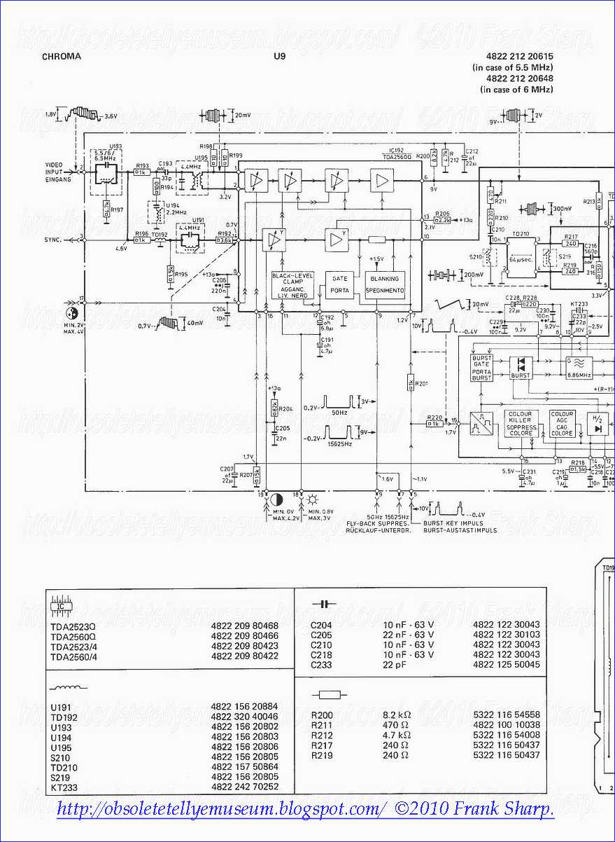


No comments:
Post a Comment
The most important thing to remember about the Comment Rules is this:
The determination of whether any comment is in compliance is at the sole discretion of this blog’s owner.
Comments on this blog may be blocked or deleted at any time.
Fair people are getting fair reply. Spam and useless crap and filthy comments / scrapers / observations goes all directly to My Private HELL without even appearing in public !!!
The fact that a comment is permitted in no way constitutes an endorsement of any view expressed, fact alleged, or link provided in that comment by the administrator of this site.
This means that there may be a delay between the submission and the eventual appearance of your comment.
Requiring blog comments to obey well-defined rules does not infringe on the free speech of commenters.
Resisting the tide of post-modernity may be difficult, but I will attempt it anyway.
Your choice.........Live or DIE.
That indeed is where your liberty lies.
Note: Only a member of this blog may post a comment.