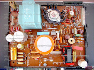


- RGB Amplifiers with TBA530 (PHILIPS) 943/K7
- Luminance + Chrominance unit 492.045 G8 with TDA2500/3 + TDA2522 (all PHILIPS)
(Note the long luminance delay line)
Video det - ampl unit : 492.089 / K WITH TDA2541 (PHILIPS)
Sound If dem + Amplifier unit : 492.319 / E with TDA2790 AND TDA1111
Frame deflection Unit : 492.308 / E
Synchronization Unit : 492.174
Line deflection Unit 492.309/D3 with TOSHIBA BU208
Power supply Unit with TOSHIBA S2530A
Tuner Prescaler + Synth Driver 592.389 with SAB1009B And ITT SAA1073
TDA2541 IF AMPLIFIER WITH DEMODULATOR AND AFC

DESCRIPTION
The TDA2540 and 2541 are IF amplifier and A.M.
demodulator circuits for colour and black and white
television receivers using PNP or NPN tuners. They
are intended for reception of negative or positive
modulation CCIR standard.
They incorporate the following functions : .Gain controlled amplifier .Synchronous demodulator .White spot inverter .Video preamplifier with noise protection .Switchable AFC .AGC with noise gating .Tuner AGC output (NPN tuner for 2540)-(PNP
tuner for 2541) .VCR switch for video output inhibition (VCR
play back).
.SUPPLYVOLTAGE : 12V TYP
.SUPPLYCURRENT : 50mATYP
.I.F. INPUT VOLTAGE SENSITIVITY AT
F = 38.9MHz : 85mVRMS TYP
.VIDEO OUTPUT VOLTAGE (white at 10% of
top synchro) : 2.7VPP TYP
.I.F. VOLTAGE GAIN CONTROL RANGE :
64dB TYP .SIGNAL TO NOISE RATIO AT VI = 10mV :
58dB TYP
.A.F.C. OUTPUT VOLTAGE SWING FOR
Df = 100kHz : 10V TYP
BU208(A)
Silicon NPNnpn transistors,pnp transistors,transistors
Category: NPN Transistor, Transistor
MHz: <1 MHz
Amps: 5A
Volts: 1500V
HIGH VOLTAGE CAPABILITY
JEDEC TO-3 METAL CASE.
DESCRIPTION
The BU208A, BU508A and BU508AFI are
manufactured using Multiepitaxial Mesa
technology for cost-effective high performance
and use a Hollow Emitter structure to enhance
switching speeds.
APPLICATIONS:
* HORIZONTAL DEFLECTION FOR COLOUR TV With 110° or even 90° degree of deflection angle.
ABSOLUTE MAXIMUM RATINGS
Symbol Parameter Value Unit
VCES Collector-Emit ter Voltage (VBE = 0) 1500 V
VCEO Collector-Emit ter Voltage (IB = 0) 700 V
VEBO Emitter-Base Voltage (IC = 0) 10 V
IC Collector Current 8 A
ICM Collector Peak Current (tp < 5 ms) 15 A
TO - 3 TO - 218 ISOWATT218
Ptot Total Dissipation at Tc = 25 oC 150 125 50 W
Tstg Storage Temperature -65 to 175 -65 to 150 -65 to 150 oC
Tj Max. Operating Junction Temperature 175 150 150 °C
FAIRCHILD LINEAR INTEGRATED CIRCUIT
GENERAL DESCRIPTION- The TDA2522 is a monolithic integrated circuit designed as
a synchronous demodulator for PAL color television receivers. It includes an 8,8 MHz

oscillator and divider to generate two 4.4 MHz reference signals and provides color difference outputs.
PACKAGE OUTLINE 9B
The TDA2522 is Intended to Interface directly with the TDA2560 with a minimum oF external components. The TDA2530 may be added if RGB drive is required. The TDA2522
is constructed using the Fairchild Planar* process.
TDA2520 COLOUR DEMODULATOR COMBINATION
The TDA2520 is an integrated synchronous demodulator combination for colour television
receivers incorporating the following functions :

~ 8, 8 MHZ oscillator followed by a divider giving two 4, 4 MHZ signals used as reference
signals
- keyed burst phase detector for optimum noise behaviour
- a stage to obtain chrominance signal control (a. c. c.) and an a. c. c. reference level
- a colour killer and identification signal detector
- two synchronous demodulators for the (B-Y) and (R-Y) signals
- temperature compensated emitter follower outputs
- PAL switch
- PAL flip-flop
- integrated capacitors in the symmetrical demodulators reduce unwanted carrier-
signals at the outputs.
TDA2593 HORIZONTAL DEFLECTION CONTROL FOR COLOR TV SET
DESCRIPTION
The TDA2593 isa circuit intended for the horizontal
deflectionof color TVsets, suppliedwith transistors
or SCR’S.
.LINE OSCILLATOR(two levels switching)
.PHASE COMPARISON BETWEEN SYNCHRO-
PULSE AND OSCILLATOR VOLTAGE
Ø 1, ENABLED BY AN INTERNAL PULSE,
(better parasitic immunity)
.PHASE COMPARISON BETWEEN THE FLYBACK
PULSES AND THE OSCILLATORVOLTAGE
Ø2
.COINCIDENCE DETECTOR PROVIDING A
LARGE HOLD-IN-RANGE .FILTER CHARACTERISTICS AND GATE
SWITCHING FOR VIDEO RECORDER APPLICATION
.NOISE GATED SYNCHRO SEPARATOR
.FRAME PULSE SEPARATOR
.BLANKING AND SAND CASTLE OUTPUT
PULSES
.HORIZONTAL POWER STAGE PHASE LAGGING
CIRCUIT
.SWITCHING OF CONTROL OUTPUT PULSE
WIDTH
.SEPARATED SUPPLY VOLTAGE OUTPUT
STAGE ALLOWING DIRECT DRIVE OF
SCR’S CIRCUIT .SECURITY CIRCUIT MAKES THE OUTPUT
PULSE SUPPRESSED WHEN LOW SUPPLY
VOLTAGE.

No comments:
Post a Comment
The most important thing to remember about the Comment Rules is this:
The determination of whether any comment is in compliance is at the sole discretion of this blog’s owner.
Comments on this blog may be blocked or deleted at any time.
Fair people are getting fair reply. Spam and useless crap and filthy comments / scrapers / observations goes all directly to My Private HELL without even appearing in public !!!
The fact that a comment is permitted in no way constitutes an endorsement of any view expressed, fact alleged, or link provided in that comment by the administrator of this site.
This means that there may be a delay between the submission and the eventual appearance of your comment.
Requiring blog comments to obey well-defined rules does not infringe on the free speech of commenters.
Resisting the tide of post-modernity may be difficult, but I will attempt it anyway.
Your choice.........Live or DIE.
That indeed is where your liberty lies.
Note: Only a member of this blog may post a comment.