


CHASSIS CUC95 UNITS VIEW
- Video RGB : 29504.005 with TDA3561A (PHILIPS)
Luminance+Chrominance+RGB MATRIX

PAL decoder TDA3561A
GENERAL DESCRIPTION
The TDA3561A is a decoder for the PAL colour television standard. It combines all functions required for the identification
and demodulation of PAL signals.
Furthermore it contains a luminance amplifier, an RGB-matrix and amplifier. These
amplifiers supply output signals up to 5 V peak-to-peak (picture information) enabling direct drive of the discrete output
stages.
The circuit also contains separate inputs for data insertion, analogue as well as digital, which can be used for text display systems (e.g. (Teletext/broadcast antiope), channel number display, etc. Additional to the TDA3560, thecircuit includes the following features:
· The peak white limiter is only active during the time that the 9,3 V level at the output is exceeded.
The start of the
limiting function is delayed by one line period. This avoids peak white limiting by test patterns which have abrupt transitions from colour to white signals.
· The brightness control is obtained by inserting a variable pulse in the luminance channel. Therefore the ratio of brightness variation and signal amplitude at the three outputs will be identical and independent of the difference in gain of the three channels. Thus discolouring due to adjustment of contrast and brightness is avoided.
· Improved suppression of the internal RGB signals when the device is switched to external signals, and vice versa.
· Non-synchronized external RGB signals do not disturb the black level of the internal signals.
· Improved suppression of the residual 4,4 MHz signal in the RGB output stages.
· Cascoded stages in the demodulators and burst phase detector minimize the radiation of the colour demodulator
inputs.
· High current capability of the RGB outputs and the chrominance output.
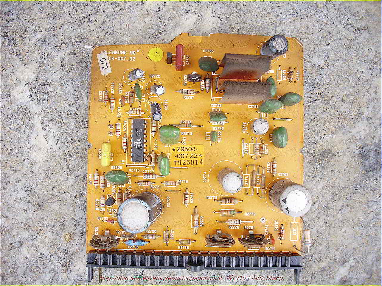
- Deflection (Ablenkung) : 29504.007.22
TDA1950 (itt), Line Circuits for TV Receivers (18-Pin Plastic Package)

These integrated circuits are advanced versions of the well-known types TDA1940, TDA1940F, TDA1950 and TDA1950F are identical
TBA940/950, TDA9400/9500 etc. integrated line oscillator circuits. except the following: at pin 2 the types having the suffix "F" supply ,
They comprise all stages for sync separation and line synchronisation horizontal output pulses of longer duration compared with the basic I
in TV receivers in one single silicon chip. Due to their high degree of types Integration, the number of external components is very small.
This integrated circuit contains the horizontal sweep generator (HO), the amplitude filter (AS), the sync-signal separating circuit (SA) and the frequency/phase comparator (FP). For the purpose of suppressing noise pulses which are caused via the operating voltage during the upper and the lower inversion point of the horizontal sweep generator (HO) which contains a single capacitor (C) and a first threshold stage circuit (SS1) with two fixed thresholds, there are provided a second and a third threshold stage circuit (SS2, SS3), to the inputs of which the sawtooth signal is applied, and with the thresholds thereof, approximately 2 μs prior to reaching the upper or the lower peak value of the sawtooth signal, are being passed through thereby. The output signal of the second threshold circuit (SS2) and the output signal of the third threshold stage circuit (SS3) which is applied via the pulse shaper circuit (IF), are superimposed linearly and, via the stopper circuit (blocking stage) (SP) serve to control the application of the composite video signal (BAS) to the amplitude filter (AS), or else they are applied to a clamping circuit which serves to apply the operating points of the amplitude filter (AS) and/or of the sync-signal separating circuit (SA) to such a potential that these two stages, for the time duration of these output pulses, are prevented from operating.
1. An integrated circuit for color television
receivers, comprising a voltage- or current-controlled horizontal
sweep generator (HO), an amplitude filter (AS), a
synchronizing-signal separating circuit (SA) and a frequency/phase
comparator (FP) which serves to synchronize the horizontal sweep
generator (HO), with said generator being a sawtooth generator
containing a single capacitor (C) and a first threshold stage circuit (SS1) having two fixed thresholds, said integrated circuit further comprising:
a second and a third threshold stage circuit (SS2, SS3) each being supplied with the sawtooth signal on the input side, comprising each time one threshold which, approximately 2μs prior to the reaching of the upper or the lower peak value of the sawtooth signal, is being passed thereby;
a pulse shaper circuit (IF) coupled to the output of said third threshold stage circuit (SS3) which pulse shaper circuit reduces the duration of the output pulse thereof to about the duration of the output pulse of said second threshold stage circuit (SS2), and
a stopper circuit (blocking stage) (SP) coupled to the outputs of both said pulse shaper circuit (IF) and said second threshold stage circuit (SS2), said stopper circuit having a signal input to which there is applied a composite video signal (BAS) and a signal output which is coupled to the input of said amplitude filter (AS).
2. The invention of claim 1 wherein the outputs of both said pulse shaper circuit (IF) and said second threshold stage circuit (SS2) are coupled to a clamping circuit which applies the operating points of said amplitude filter (AS) and said sync-separating signal (SA) to such a potential that they are prevented from operating.
3. An integrated horizontal sweep circuit comprising:
a generator for generating a sawtooth signal;
an amplitude filter having an input for receiving a composite video signal and having an output;
a sync-signal separating circuit having an input coupled to said amplitude filter output and having an output;
a frequency/phase comparator having a first input coupled to said separating circuit output,
a second input receiving said sawtooth signal and an output for controlling said generator; and
a control circuit responsive to said sawtooth signal for inhibiting said composite video signal when said sawtooth signal is within predetermined signal level ranges about the upper and lower inversion points of said sawtooth signal.
4. An integrated circuit in accordance with claim 3 wherein:
said generator comprises a capacitor, circuit means for charging and discharging said capacitor, and a first threshold circuit controlling said circuit means in response to said sawtooth signal reaching a first level corresponding to said first inversion point and a second level corresponding to said second inversion point.
5. An integrated horizontal sweep circuit comprising:
a sawtooth signal generator;
an amplitude filter having an input receiving a composite video signal and having an output;
a sync-signal separating circuit having an input coupled to said amplitude filter output and having an output;
a frequency/phase comparator having a first input coupled to said separating circuit output, a second input receiving said sawtooth signal and an output for controlling said generator; and
a control circuit responsive to said sawtooth signal for inhibiting operation of said amplitude filter and/or said sync-signal separating circuit when said sawtooth signal is within predetermined signal level ranges about the upper and lower inversion point of said sawtooth signal.
6. An integrated circuit in accordance with claim 5 wherein:
said generator comprises a capacitor, circuit means for charging and discharging said capacitor and a first threshold circuit controlling said circuit means in response to said sawtooth signal reaching a first level corresponding to said first inversion point and a second level corresponding to said second inversion point.
The
invention relates to an integrated circuit for (color) television
receivers, comprising a voltage- or current-controlled
horizontal-sweep generator, an amplitude filter, a synchronizing
signal separating circuit (sync-separator) and a frequency/phase
comparator which serves to synchronize the horizontal sweep
generator which is a sawtooth generator consisting of a single
capacitor and of a first threshold stage having two fixed switching
thresholds, cf. preamble of the patent claim. Such types of
integrated circuits, for example, are known from the technical journal "Elektronik aktuell", 1976, No. 2, pp. 7 to 14 where they are referred to as TDA 9400 and TDA 9500.Especially on account of the fact that the amplitude filter as well as the horizontal sweep generator in the form of the aforementioned sawtooth generator, are integrated on a single semiconductor body, it is likely that noise interference pulses coming from the individual stages, and via the supply voltage line, may have a disturbing influence upon the horizontal sweep generator, i.e. upon the threshold stage thereof, in such a way that either the lower or the upper or successively both switching thresholds are exceeded before the time by the voltage at the capacitor, owing to the noise superposition, so that the generator will show to have a "wrong" frequency or phase position. This frequency/phase variation, of course, is compensated for by the circuit, with the aid of the synchronzing pulses, but only in such a way that the noise effect remains visible in the television picture.
SUMMARY OF THE INVENTION
The invention is characterized in the claim is aimed at overcoming this drawback by solving the problem of designing an integrated circuit of the type described in greater detail hereinbefore, in such a way that noise pulses acting upon the capacitor voltage or the internal reference voltages for the switching thresholds (see below) in the proximity of the two switching thresholds, are prevented from having the described disadvantageous effect. Accordingly, an advantage of the invention results directly from solving the given problem.
Other objects, features and advantages of the present invention will become more fully apparent from the following detailed description of the preferred embodiment, the appended claims and the accompanying drawing in which:
BRIEF DESCRIPTION OF THE INVENTION
The invention will now be described in greater detail with reference to the accompanying drawing. This drawing, in the form of a schematical circuit diagram, shows the construction of an integrated circuit according to the invention.
DETAILED DESCRIPTION OF THE INVENTION
The
horizontal sweep generator HO comprises the capacitor C as
connected to the zero point of the circuit, and which is charged and
discharged via the two shown constant current sources CS1 and
CS2, thus causing the intended sawtooth voltage to appear thereat.
Moreover, the horizontal sweep generator HO comprises the first
threshold stage circuit SS1, having an upper and a lower threshold.
As soon as the capacitor voltage exceeds one of the thresholds,
the first threshold stage circuit SS1 switches over to the other
threshold. The two thresholds are defined by the voltage divider P
as connected to the operating voltage U, and in which the
corresponding threshold inputs are connected to corresponding
tapping points. The output of the threshold stage circuit SS1
controls the electronic switch S, so that the constant current
source CS2 as connected thereto, is either disconnected from or
connected to the zero point of the circuit. Accordingly, in the
disconnected state, the capacitor C is charged via the constant
current source CS1 arranged in series therewith while in the
connected state the capacitor C is discharged across the
aforementioned constant current source CS2 arranged in parallel
therewith, if, as a matter of fact, the current of the constant
current source CS1 arranged in series with the capacitor C, is
smaller than that of the parallel-arranged constant current source
CS2.Now, for the purpose of avoiding the aforementioned drawbacks, there is provided a second and a third threshold stage circuit SS2 and SS3, respectively, as well as the pulse shaper circuit IF. To the respective input of the two threshold stage circuits SS2, SS3, there is applied the capacitor voltage, in the form of the sawtooth signal, and these stages have a threshold voltage which, approximately 2 μs prior to the reaching of the upper or the lower peak value of the sawtooth voltage, is being passed thereby. This means to imply that the threshold voltage of the second threshold stage circuit SS2 is somewhat lower than the voltage of the upper threshold of the first threshold stage circuit SS1, and that the threshold voltage of the third threshold stage circuit SS3 is somewhat higher than the voltage of the lower threshold of the first threshold stage circuit SS1. The two thresholds of the threshold stage circuits SS2, SS3 can thus be realized in a simple way by providing further tapping points at the voltage divider P, as is shown in the accompanying drawing. Thus, the second threshold stage circuit SS2 is provided for at a voltage divider tapping point below the tapping point chosen for the upper threshold, and the tapping point for the third threshold stage circuit SS3 is provided for above the tapping point which has been chosen for the lower threshold of the first threshold stage circuit SS1.
Since, within the area of the lower inversion point of the sawtooth signal there results an excessively wide output pulse of the third threshold stage circuit SS3, the pulse shaper circuit IF is arranged subsequently thereto, for reducing the duration of the output pulse as applied to its input, to about the duration of the output pulse of the second threshold stage circuit SS2. This pulse shaper circuit IF, for example, may be realized by a monoflop, in particular by a digital monoflop (=monostable circuit).
The output pulses of the second threshold stage circuit SS2 and of the pulse shaper circuit IF are then super-positioned linearly, with this being denoted in the drawing by a simple interconnection of the two respective lines. The combined signal is applied to the input of the stopper circuit (blocking stage) SP, to the signal input of which there is fed the composite video signal BAS, and the output thereof controls both the amplitude filter AS and the synchronizing signal separating circuit SA.
The combined signal may also be used to control a clamping circuit applying the operating points of the amplitude filter AS and/or of the sync-signal-separating circuit SA to such a potential which prevents it from operating.
If
now the sawtooth signal reaches the range of its upper or its
lower inversion point, the composite video signal BAS is not
applied to either the amplitude filter AS or the sync-signal
separating circuit SA, so that shortly before and shortly after the
inversion points, signals are prevented from being processed in
the two stages AS, SA. This, in turn, has the consequence that
during these times noise pulses are prevented from superimposing
upon the operating voltage U, so that there is also prevented an
unintended triggering of the first threshold stage circuit SS1.Moreover, it is still shown in the drawing that the amplitude filter AS, the sync-signal separating circuit SA and the frequency/phase comparator FP are arranged in series in terms of signal flow, with the latter, in addition, receiving the sawtooth signal, and with the output signal thereof acting upon the two current sources in a regulating sense. In the drawing, this is indicated by the setting arrows at the two current sources.
While the present invention has been disclosed in connection with the preferred embodiment thereof, it should be understood that there may be other embodiments which fall within the spirit and scope of the invention as defined by the following claims.
- Tuner with TUA2000 + TBA1440 (SIEMENS)


The TUA 2000-4 is a monolithically integrated circuit and suitable as a tuner for the VHF
range up to 400 Mkz, e.g. for TV tuners.
RF section
Few externa! components
Stable oscillator frequency and amplitude with very low interference radiation
Optimal rejection of oscillator and input frequencies at the IF output due to a decoupled
active ring mixer circuit
High interference voltage resistance
High-impedance mixer input, for symmetrical and asymmetrical connections
IF post-amplifier for the UHF IF signal
IF section
@
Optimal cross-talk rejection
@
Large signal-modulation range
@
Low noise figure with wide minimum over large load-impedance range
Circuit description
The TUA 2000-4 contains a symmetrical mixer input, as well as a multiplicative mixer. The
oscillator amplitude is regulated. All oscillator operating currents and voltages are stabilized,
so that the oscillator’s amplitude and frequency are largely independent of temperature
and operating voltage changes.
The IF amplifier has been provided with a high impedance input.
The output has two open collector connections.
During UHF operation, oscillator and mixer are switched off and the UHF IF input coupling
stage is activated.
RF section
Few external components
Stable oscillator frequency and amplitude with very low interference radiation
Optimal rejection of oscillator and input frequencies at the iF output due to a decoupled
active ring mixer circuit
High interference voltage resistance
High-impedance mixer input, for symmetrical and asymmetrical connections
IF post-amplifier for the UHF IF signa!
IF section
@
Optima! cross-talk rejection
@
Large signal-modulation range
@
Low noise figure with wide minimum over large load-impedance range
Pin description
- “Open collector” output of the IF SAW driver
- “Open collector” output of the IF SAW driver
- Input for external reference voltage
- Low-ohmic collector output to the high reference point of a parallel resonant circuit
- High-ohmic base input to the high reference point of a parallel resonant circuit
- Oscillator signal output for counter connection
- GND
- “Open collector” output of the mixer
- “Open collector” output of the mixer
- Supply voltage
- Asymmetrical IF signal input for the UHF IF signal
- Mixer high-impedance differential input
- Mixer high-impedance differential input
- Switching voltage input for the VHF-UHF switch selection
- Asymmetrical signal input of the IF SAW amplifier
- GND
Power supply is based of TDA4600 and BU208A
Line deflection output is with BU208A
BU208(A)
Silicon NPNnpn transistors,pnp transistors,transistors
Category: NPN Transistor, Transistor
MHz: <1 MHz
Amps: 5A
Volts: 1500V
HIGH VOLTAGE CAPABILITY
JEDEC TO-3 METAL CASE.
DESCRIPTION
The BU208A, BU508A and BU508AFI are
manufactured using Multiepitaxial Mesa
technology for cost-effective high performance
and use a Hollow Emitter structure to enhance
switching speeds.
APPLICATIONS:
* HORIZONTAL DEFLECTION FOR COLOUR TV With 110° or even 90° degree of deflection angle.
ABSOLUTE MAXIMUM RATINGS
Symbol Parameter Value Unit
VCES Collector-Emit ter Voltage (VBE = 0) 1500 V
VCEO Collector-Emit ter Voltage (IB = 0) 700 V
VEBO Emitter-Base Voltage (IC = 0) 10 V
IC Collector Current 8 A
ICM Collector Peak Current (tp < 5 ms) 15 A
TO - 3 TO - 218 ISOWATT218
Ptot Total Dissipation at Tc = 25 oC 150 125 50 W
Tstg Storage Temperature -65 to 175 -65 to 150 -65 to 150 oC
Tj Max. Operating Junction Temperature 175 150 150 °C
No comments:
Post a Comment
The most important thing to remember about the Comment Rules is this:
The determination of whether any comment is in compliance is at the sole discretion of this blog’s owner.
Comments on this blog may be blocked or deleted at any time.
Fair people are getting fair reply. Spam and useless crap and filthy comments / scrapers / observations goes all directly to My Private HELL without even appearing in public !!!
The fact that a comment is permitted in no way constitutes an endorsement of any view expressed, fact alleged, or link provided in that comment by the administrator of this site.
This means that there may be a delay between the submission and the eventual appearance of your comment.
Requiring blog comments to obey well-defined rules does not infringe on the free speech of commenters.
Resisting the tide of post-modernity may be difficult, but I will attempt it anyway.
Your choice.........Live or DIE.
That indeed is where your liberty lies.
Note: Only a member of this blog may post a comment.