
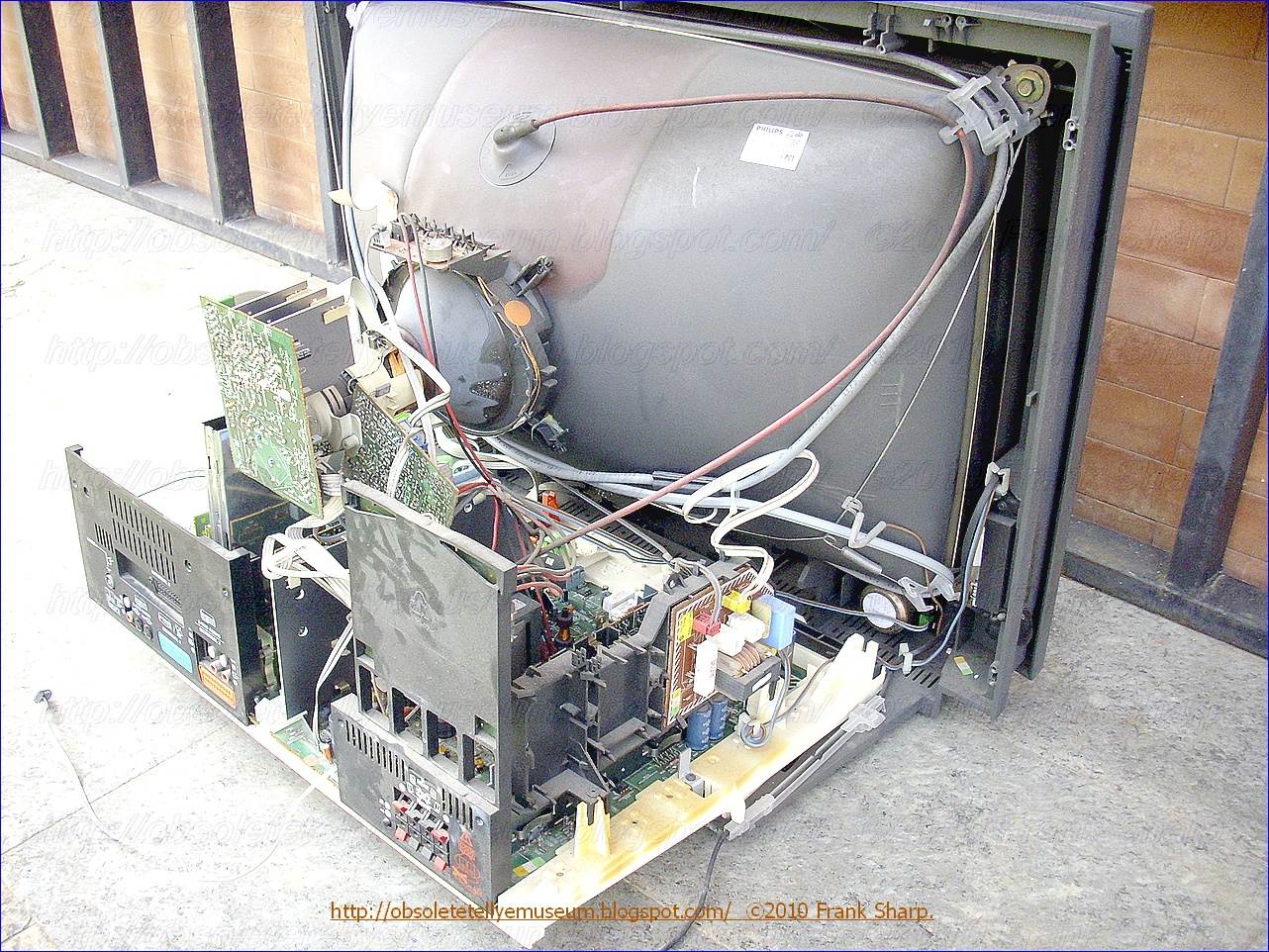


CRT TUBE PHILIPS W67EWR001X42 45AX SYSTEM.It has even Digital controlled beam scan velocity modulation (SVM) with a unit fitted on the tube neck.
PHILIPS 28PW9608 MATCHLINE IDTV 100HZ CHASSIS FL2.24 AA CRT TUBE PHILIPS W67EWR001X42 45AX SYSTEM.In beam scan velocity modulation (SVM) system for a television receiver,
 a
video signal is applied to a differentiator followed by a limiting
differential amplifier. A driver amplifier coupled to the limiting
amplifier drives an output stage that supplies current to an SVM coil.
Certain video signals with large high frequency content may tend to
produce excessive dissipation in the devices of the output stage. To
prevent this, a current source for the differential amplifier is
controlled by a voltage which is a measure of the average current
through the output stage. The magnitude of the current source is varied
to thereby vary the peak-to-peak signal output from the limiting
amplifier to prevent overdissipation of the output devices. The presence
of random noise in the video signal can produce unwanted SVM operation
which can impair the viewed image. The unwanted noise component in the
video signal can be reduced in amplitude by coring. The coring is
unaffected by the variable limiting.
a
video signal is applied to a differentiator followed by a limiting
differential amplifier. A driver amplifier coupled to the limiting
amplifier drives an output stage that supplies current to an SVM coil.
Certain video signals with large high frequency content may tend to
produce excessive dissipation in the devices of the output stage. To
prevent this, a current source for the differential amplifier is
controlled by a voltage which is a measure of the average current
through the output stage. The magnitude of the current source is varied
to thereby vary the peak-to-peak signal output from the limiting
amplifier to prevent overdissipation of the output devices. The presence
of random noise in the video signal can produce unwanted SVM operation
which can impair the viewed image. The unwanted noise component in the
video signal can be reduced in amplitude by coring. The coring is
unaffected by the variable limiting.1. Field of the Invention
This invention relates generally to beam scan velocity modulation (SVM) systems employed for picture sharpness enhancement and more particularly to an output current limiting, apparatus employed in an SVM system.
2. Description of the Related Art It is well known that an improvement in apparent picture resolution can be achieved by modulating the beam scan velocity in accordance with the derivative of the video signal which controls the beam intensity. This video signal is referred to as the luminance signal and the derivative of the luminance signal is employed for such control. An advantage of this method over a peaking approach to picture sharpness enhancement is the avoidance of blooming of peaked white picture elements.
It is known in the prior art to apply a differentiated video signal to the input of a double ended limiter incorporating a pair of threshold circuits. The limiter consists of two separate differential amplifiers, where each amplifier is separately biased to provide double ended limiting as well as to provide coring. The limiter arrangement develops a doubly clipped signal output which does not respond to excursions of the differentiated signal which lie below selected threshold magnitudes. Thus the gain of the limiter is such as to provide sharpness enhancement for slow transients while precluding excessive supplemental beam deflection with fast transients. The coring capability of the limiter arrangement significantly lessens the likelihood of noise visibility.
It may be desirable, however, to use a single differential amplifier stage, followed by another stage which will provide the coring function. In such an arrangement, it may be easier to design cost effective circuitry that still meets the requirements of a flat group delay response.
As indicated above, in order to provide beam scan velocity modulation, one differentiates the video signal. A differentiator has an increasing output with increasing frequency. Thus, if the input video signal has higher than normal high frequency components, then a linear system would deliver higher than normal output current and dissipate higher than normal power in the output stage. In such a prior art system, it is possible to overdissipate the output stages of the beam scan velocity modulation system by responding to a particular video signals with much high frequency content.
 Circuits are known in the prior art which, in
addition to providing signal limiting, reduce power dissipation in the
output stages. In such circuits, the current flowing in the output power
amplifier is detected to provide a control signal used to control the
gain of a preamplifier in a preceding stage. This action suppresses the
increase of power dissipation in the output power amplifier when a video
signal of a certain frequency characteristic is received. No coring of
the differentiated signal is provided, and hence there is exhibited
inferior operation in the presence of noise. Furthermore, since the
feedback reduces the signal gain as a function of output power, overall
SVM operation is reduced, tending to produce a less pleasing visual
effect.
Circuits are known in the prior art which, in
addition to providing signal limiting, reduce power dissipation in the
output stages. In such circuits, the current flowing in the output power
amplifier is detected to provide a control signal used to control the
gain of a preamplifier in a preceding stage. This action suppresses the
increase of power dissipation in the output power amplifier when a video
signal of a certain frequency characteristic is received. No coring of
the differentiated signal is provided, and hence there is exhibited
inferior operation in the presence of noise. Furthermore, since the
feedback reduces the signal gain as a function of output power, overall
SVM operation is reduced, tending to produce a less pleasing visual
effect. Still other circuits are known which operate in a different manner to limit power dissipated in the SVM output stages. In these circuits parallel resistor capacitor combinations with long time constants are provided. These RC combinations are in series with emitter electrodes of transistors which are employed in the output power amplifiers of the SVM system. The transistors operate in a Class B mode with the top transistor conducting on one half cycle of its input waveform and with the bottom device conducting on the other half cycle.
Using this scheme, the bias of the base emitter junction becomes a function of the average amount of high frequency detail in the television image and thereby undesirably introduces more or less output stage coring of the signal depending upon the scene information. Furthermore, this approach requires relatively large magnitude, high voltage capacitors which are expensive and bulky.
As an example, the capacitors used may be 47 μf in value and the resistors 20 ohms in value. The voltage requirements on the capacitors may be in excess of 150 volts. Hence, these capacitors are quite large, bulky and expensive.
SUMMARY OF THE INVENTION
In accordance with an inventive arrangement, a first amplifier is responsive to an input video signal and provides peak-to-peak limiting. A driver amplifier receives the limited signal via a buffer amplifier and provides noise coring subsequent to limiting. An output amplifier coupled to the driver amplifier energizes a scan velocity modulation circuit in accordance with the limited and noise cored video signal.
In accordance with another inventive arrangement, a scan velocity modulation circuit includes means for monitoring the current in the output stage of the SVM circuit and controlling the operation of a preceding stage differential amplifier in accordance with the monitored current. Advantageously, this can prevent overdissipation in the output stage.
1. Field of the Invention
The present invention relates to a
beam scan velocity modulation (SVM) apparatus, and more particularly to a
beam scan velocity modulation apparatus with an SVM disabling circuit
employed for picture sharpness enhancement. 
2. Description of the Prior Art
It is well known that an improvement in apparent picture resolution can be achieved by the use of modulation of the beam scan velocity in accordance with the derivative of a video signal which controls the beam intensity. This video signal is known as the luminance signal and the derivative of the luminance signal is employed for the beam SVM. The beam SVM will improve the picture sharpness in a color television system employing a color kinescope.
Many modern color television receivers also employ alternate video sources. An example of such an alternate video source is commonly referred to as an on screen display (OSD) generator. The function of the OSD generator is to provide additional display informations to a viewer while viewing a typical television program. Thus, OSD generator provides for the display on the television screen of time, day, channel number and other various control informations.
In implementing OSD display, the OSD informations are presented as graphical data together with the normal pictures.
Techniques for generating this type of graphical data which is superimposed upon the television picture are well known in the art. Such techniques include OSD generators which count television scan lines and insert at the correct pixel locations the proper graphics to thereby display the time of day, channel number and words such as "CONTRAST", "COLOR", "MUTE" and so on. The use of an on screen display and an associated OSD generator requires the substitution of a different video signal or kinescope drive for the normal video signal which is being processed by the television receiver. In this manner, the pertinent information can be superimposed upon the viewed image.
 A scan modulation circuit
modulates the picture displayed on a display device in accordance with
the video content of a first video signal. An alternate video signal
possesses its picture informations displayed on the display device when
the alternate signal is selected. The operation of the scan modulation
circuit is varied in accordance with this selection. A problem may occur
in regard to scan velocity modulation in television receivers which
also include an alternate video signal source such as on screen display
generator. As is known, the SVM apparatus operates to modulate the
horizontal beam scan velocity in response to differentiated luminance
information from the main video source. This modulation may occur prior
to OSD deletion of the main luminance signal and insertion of the
character signal.
A scan modulation circuit
modulates the picture displayed on a display device in accordance with
the video content of a first video signal. An alternate video signal
possesses its picture informations displayed on the display device when
the alternate signal is selected. The operation of the scan modulation
circuit is varied in accordance with this selection. A problem may occur
in regard to scan velocity modulation in television receivers which
also include an alternate video signal source such as on screen display
generator. As is known, the SVM apparatus operates to modulate the
horizontal beam scan velocity in response to differentiated luminance
information from the main video source. This modulation may occur prior
to OSD deletion of the main luminance signal and insertion of the
character signal. U.S. Pat. No. 5,072,300 (issued to Mark R. Anderson) discloses a beam scan velocity modultion apparatus, which controls the current in a scan velocity modulation (SVM) coil by a blanking pulse in order to eliminate the effect of SVM artefact generation during the operation of an OSD generator in a television receiver. In this arrangement, a ghost image representative of the deleted portions of the main luminance signal may appear on the television screen near or behind the inserted OSD character information since the current flowing in the SVM coil is not completely controlled. The ghost image behind the characters generated by the OSD display appears as an outline of the picture contained in the deleted portions of the main luminance signal.
SUMMARY OF THE INVENTION
The object of the present invention is to provide a beam scan velocity modulation (SVM) apparatus with an SVM disabling circuit capable of eliminating the above-mentioned picture interference when OSD display information and TELETEXT information are displayed over a certain display size on the screen.
In order to achieve the above object, the beam scan velocity modulation (SVM) apparatus with an SVM disabling circuit according to the present invention comprises:
a picture display device;
a source of a first video signal having a picture information displayed on the picture display device when the source is selected;
an OSD/TELETEXT display generator having on-screen display information or teletext display information displayed on the picture display device when the OSD/TELETEXT display generator is selected, the OSD/TELETEXT display generator producing pul
ses on a line-by-line basis and a certain
level of a dc voltage indicative of insertion of the picture
information and of a full-screen teletext display information; a scan velocity modulating circuit coupled to the source for modulating information displayed on the device in accordance with the video content of the first video signal; and
an SVM disabling circuit responsive to the pulses and the dc voltage and coupled to the scan velocity modulating circuit for modifying operation of the scan velocity modulating circuit when the OSD/TELETEXT display generator is selected.
With the beam scan velocity modulation apparatus with SVM disabling circuit, an OSD display over a certain display size or a full-screen teletext display is obtained on the screen without any ghost image caused by a luminance signal.
-----------------------------------------------------------
INTRODUCTION:
This type the 45AX FST TUBE BY PHILIPS WAS WIDELY USED AROUND THE WORLD and fabricated form more than 22 YEARS.
Picture display system including a deflection unit with a double saddle coil system
PHILIPS 45AX SYSTEM
Self-convergent
picture display system with a color display tube and an
electromagnetic deflection unit including a field deflection coil and a
line deflection coil which are both of the saddle type and are
wound directly on a support. The deflection unit includes a pair of
magnetically permeable portions which are arranged symmetrically
with respect to the plane of symmetry of the field deflection coil
on either side of the tube axis. The magnetically permeable portion
draws magnetic flux from the end of the yoke ring in order to extend
the vertical deflection field. A self-convergent system can be
realized with different screen formats by choosing different lengths
of the magnetically permeable portions.

What is claimed is:
1. A picture display system including a colour display tube having a neck accommodating an electron gun assembly for generating three electron beams, and an electromagnetic deflection unit surrounding the paths of the electron beams which have left the electron assembly, said deflection unit comprising
a field deflection coil of the saddle type having a front and a rear end for deflecting electron beams generated in the display tube in a vertical direction;
a line deflection coil of the saddle type likewise having a front and a rear end for deflecting electron beams generated in the display tube in a horizontal direction, and a yoke ring of ferromagnetic material surrounding the two deflection coils and having front and rear end faces extending transversely to the tube axis, the electron beam traversing the coils in the direction from the rear to the front ends when the deflection unit is arranged on a display tube, characterized in that the deflection unit also has first and second magnetically permeable portions arranged symmetrically with respect to the plane of symmetry of the field deflection coil on either side of the tube axis, each magnetically permeble portion having a first end located opposite the rear end face of the yoke ring and a second end located at the neck of the display tube in the proximity of the location where the electron beams leave the electron gun assembly, the length of the first and second magnetically permeable portions and their distance to the yoke ring being dimensioned for providing a self-convergent picture display system.
2.
A picture display system as claimed in claim 1 characterized in
that regions of the rear end of the yoke ring located on either side
of the plane of symmetry of the line deflection coil are left free
by the rear end of the field deflection coil and in that the first
ends of the magnetically permeable portions are located opposite
said regions.
 3. A picture display system as claimed in claim 1
characterized in that the field deflection coil and the line
deflection coil are directly wound on a support.
3. A picture display system as claimed in claim 1
characterized in that the field deflection coil and the line
deflection coil are directly wound on a support.
4. Apparatus for adapting a self-convergent deflection unit of the type mountable on the neck of a display tube and including a saddle type field deflection coil screen end and a gun end extending away from said tube in a plane disposed at an angle to a tube axis, and a yoke ring having a screen end and a gun end, for use with display tubes having different screen formats comprising:
format adjustment means disposed adjacent to the gun end of the yoke ring for coupling flux from the yoke ring to the neck of the tube to supplement the field produced by the vertical deflection coil to uniformly increase the vertical deflection field to produce a raster having a different format from the raster produced by said deflection unit alone.
 3. A picture display system as claimed in claim 1
characterized in that the field deflection coil and the line
deflection coil are directly wound on a support.
3. A picture display system as claimed in claim 1
characterized in that the field deflection coil and the line
deflection coil are directly wound on a support.4. Apparatus for adapting a self-convergent deflection unit of the type mountable on the neck of a display tube and including a saddle type field deflection coil screen end and a gun end extending away from said tube in a plane disposed at an angle to a tube axis, and a yoke ring having a screen end and a gun end, for use with display tubes having different screen formats comprising:
format adjustment means disposed adjacent to the gun end of the yoke ring for coupling flux from the yoke ring to the neck of the tube to supplement the field produced by the vertical deflection coil to uniformly increase the vertical deflection field to produce a raster having a different format from the raster produced by said deflection unit alone.

5.
The apparatus of claim 4 wherein said field deflection coil is
arranged symmetrically about a plane of symmetry passing through said
neck and said format adjustment means comprises first and second
magnetically permeable members arranged symmetrically about said plane
of symmetry, each of said magnetically permeable members having a
first end disposed adjacent the gun end of the yoke ring and a second
end disposed adjacent the neck of the display tube.
6. The apparatus of claim 5 wherein each of said first and second magnetically permeablel members comprises a first end located opposite a gun end face of the yoke ring, and a second end located at the neck of the display tube adjacent the location where the electron beams leave the electron gun assembly.
7. The apparatus of claim 6 wherein said first end comprises a portion of said permeable member disposed parallel to the neck of the displaya tube and said second end comprises a portion of said magnetically permeable member located perpepndicular to the neck of the display tube.
8. The apparatus of claim 7 wherein said second endsn of said magnetically permeable members have inwardly extending arms subending a first angle.
9. The appaaratus of claim 8 wherein said angle is large so that the supplemental field has a positive sixpole component.

10.
The apparatus of claim 8 wherein said angle is very small, so that
said supplemental field has a dipole component and a negative
sixpole component.
11. Apparatus for adapting a self-convergent deflection unit of the type used on the neck of a display tube having an electron gun disposed in a neck of said tube, said deflection unit including a field deflection coil of the saddle type having a rear end portion disposed at an angle to the axis of said tube, comprising means disposed adjacent to said neck between said electron gun and said deflection unit, and coupled to said deflection unit for changing the distance between the line and field deflection points for causing said deflection unit to produce a different screen format.
11. Apparatus for adapting a self-convergent deflection unit of the type used on the neck of a display tube having an electron gun disposed in a neck of said tube, said deflection unit including a field deflection coil of the saddle type having a rear end portion disposed at an angle to the axis of said tube, comprising means disposed adjacent to said neck between said electron gun and said deflection unit, and coupled to said deflection unit for changing the distance between the line and field deflection points for causing said deflection unit to produce a different screen format.
BACKGROUND OF THE INVENTION The
invention relates to a picture display system including a colour
display tube having a neck accommodating an electron gun assembly for
generating three electron beams, and an electromagnetic deflection
unit including a field
deflection coil of the saddle type having a front and a rear end for
deflecting electron beams generated in the display tube in a
vertical direction and a
line deflection coil of the saddle type likewise having a front and a
rear end for deflecting electron beams generated in the display tube
in a horizontal direction and yoke ring of ferromagnetic material
surrounds the two deflection coils and has front and rear end faces
extending transversely to the tube axis, the electron beam traversing
the coils in the direction from the rear to the front ends when the
deflection unit is arranged on a display tube. FOr
some time a colour display tube has become the vogue in which three
electron beams are used in one plane; the type of such a cathode
ray tube is sometimes referred to as "in-line". In this case, for
decreasing convergence errors of the electron beams, a deflection
unit is used having a line deflection coil generating a horizontal
deflection field of the pincushion type and a field deflection coil
generating a vertical deflection field of the barrel-shaped type. Deflection
units for in-line colour display tube systems can in principle be
made to be entirely self-convergent, that is to say, in a design of
the deflection unit which ensures convergence of the three electron
beams on the axes, anisotropic y-astigmatism errors, if any, can
simultaneously be made zero in the corners without this requiring
extra correction means. While it would be interesting from a point of
view of manufacture to have a deflection unit which is
selfconvergent for a family of display tubes of the same deflection
angle and neck diameter, but different screen formats, the problem
exists, however, that a deflection unit of given main dimensions can
only be used for display tubes of one screen format. This means
that only one screen format can be found for a fixed maximum
deflection angle in which aa given deflection unit is
self-convergent without a compromise (for example, the use of extra
correction means).  The
Netherlands Patent Specification 174 198 provides a solution to
this problem which is based on the fact that, starting from field
and line deflection coils having given main dimensions,
selfconvergent deflection units for a family of display tubes having
different screen formats can be assembled by modifying the
effective lengths of the field and line deflection coils with
respect to each other. This solution is based on the recognition
that, if selfconvergence on the axes has been reached, the possibly
remaining anisotropic y-astigmatism error (particularly the
y-convergence error halfway the diagonals) mainly depends on the
distance between the line deflection point and the field deflection
point and to a much smaller extent on the main dimensions of the
deflection coils used. If deflection units for different screen
formats are to be produced while using deflection coils having the
same main dimensions, the distance between the line and field
deflection points may be used as a parameter to achieve
self-convergence for a family of display tubes having different
screen formats but the same maximum deflection angle. The
variation in the distance between the line and field deflection
points necessary for adaption to different screen formaats is
achieved in the prior art by either decreasing or increasing the
effective coil length of the line deflection coil or of the field
deflection coil, or of both - but then in the opposite sense - with
the maiin dimensions of the deflection coils remaining the same and
with the dimensions of the yoke ring remaining the same, for
example, by mechanically making the coil or coils on the rear side
smaller and longer, respectively, by a few millimeters, or by
positioning, with the coil length remaining the same, the coil
window further or less far to the rear (so thata the turns on the
rear side are more or less compressed). To achieve this,
saddle-shaped line and field deflection coils of the shell type were
used. These are coils having ends following the contour of the neck
of the tube at least on the gun side. This is in contrast to the
conventional saddle coils in which the gun-sided ends, likewise as the
screen-sided ends, are flanged and extend transversely to the tube
surface. When using saddle coils of the shell type it is possible
for the field deflection coil (and hence the vertical deflection
field) to extend further to the electron gun assembly than the line
deflection coil, if the field design so requires. However, there are
also deflection units with deflection coils of the conventional
saddle type, which means that - as stated - they have front and rear
ends located in planes extending at an angle (generally of
90.degree. ) to the tube axis. (A special type of such a deflection
unit with conventional saddle coils is, for example, the deflection
unit described in EP 102 658 with field and line deflection coils
directly wound on a support). In this case it has until now been
impossible to extend the vertical deflection field further to the
electron gun assembly than the horizontal deflection field, because
the field deflection coil is enclosed between the flanges of the line
deflection coil.
The
Netherlands Patent Specification 174 198 provides a solution to
this problem which is based on the fact that, starting from field
and line deflection coils having given main dimensions,
selfconvergent deflection units for a family of display tubes having
different screen formats can be assembled by modifying the
effective lengths of the field and line deflection coils with
respect to each other. This solution is based on the recognition
that, if selfconvergence on the axes has been reached, the possibly
remaining anisotropic y-astigmatism error (particularly the
y-convergence error halfway the diagonals) mainly depends on the
distance between the line deflection point and the field deflection
point and to a much smaller extent on the main dimensions of the
deflection coils used. If deflection units for different screen
formats are to be produced while using deflection coils having the
same main dimensions, the distance between the line and field
deflection points may be used as a parameter to achieve
self-convergence for a family of display tubes having different
screen formats but the same maximum deflection angle. The
variation in the distance between the line and field deflection
points necessary for adaption to different screen formaats is
achieved in the prior art by either decreasing or increasing the
effective coil length of the line deflection coil or of the field
deflection coil, or of both - but then in the opposite sense - with
the maiin dimensions of the deflection coils remaining the same and
with the dimensions of the yoke ring remaining the same, for
example, by mechanically making the coil or coils on the rear side
smaller and longer, respectively, by a few millimeters, or by
positioning, with the coil length remaining the same, the coil
window further or less far to the rear (so thata the turns on the
rear side are more or less compressed). To achieve this,
saddle-shaped line and field deflection coils of the shell type were
used. These are coils having ends following the contour of the neck
of the tube at least on the gun side. This is in contrast to the
conventional saddle coils in which the gun-sided ends, likewise as the
screen-sided ends, are flanged and extend transversely to the tube
surface. When using saddle coils of the shell type it is possible
for the field deflection coil (and hence the vertical deflection
field) to extend further to the electron gun assembly than the line
deflection coil, if the field design so requires. However, there are
also deflection units with deflection coils of the conventional
saddle type, which means that - as stated - they have front and rear
ends located in planes extending at an angle (generally of
90.degree. ) to the tube axis. (A special type of such a deflection
unit with conventional saddle coils is, for example, the deflection
unit described in EP 102 658 with field and line deflection coils
directly wound on a support). In this case it has until now been
impossible to extend the vertical deflection field further to the
electron gun assembly than the horizontal deflection field, because
the field deflection coil is enclosed between the flanges of the line
deflection coil.
SUMMARY OF THE INVENTION The deflection unit has first and second magnetically permeable portions arranged symmetrically with respect to the plane of symmetry of the field deflection coil on either side of the tube axis, each magnetically permeable portion having a first end located opposite the rear end face of othe yoke ring and a second end located at the neck of the display tube in the proximity of the location where the electron beams leave the electron gun assembly. The length of the first and second magnetically permeable portions and their distance to the yoke ring are dimensioned for providing a self-convergent picture display system. The invention is based on the recognition that the first ends of the magnetically permeable portions draw a field deflection flux flux which is taken up is adjusted by means of the distance between the first ends and the yoke ring, and the length of the magnetically permeable portions determines how far the vertical deflection field is extended to the rear. A practical embodiment of the picture display system according to the invention is characterized in that regions of the rear end of the yoke ring located on either side of the plane of symmetry of the line deflection coil are left free by the rear end of the field deflection coil and in that the first ends of the magnetically permeable portions are located opposite said regions. The invention can particularly be used to advanatage if the field deflection coil and the line deflection coil are directly wound on a support. The invention also relates to an electromagnetic deflection unit suitable for use in a picture display system as described hereinbefore. For use in a display tube having a larger screen format than the display tube for which it is designed, the invention provides the possibility of moving apart the deflection points of the horizontal deflection field and the vertical deflection field generated by a given deflection unit having saddle coils and of moving them towards each other for use in a display tube having a smaller screen format. The great advantage of the invention is that only a modification of the length of the magnetically permeable portions (providing or omitting them, respectively) is required to adapt a deflection unit to different screen formats of a display tube family.
 The
Netherlands Patent Specification 174 198 provides a solution to
this problem which is based on the fact that, starting from field
and line deflection coils having given main dimensions,
selfconvergent deflection units for a family of display tubes having
different screen formats can be assembled by modifying the
effective lengths of the field and line deflection coils with
respect to each other. This solution is based on the recognition
that, if selfconvergence on the axes has been reached, the possibly
remaining anisotropic y-astigmatism error (particularly the
y-convergence error halfway the diagonals) mainly depends on the
distance between the line deflection point and the field deflection
point and to a much smaller extent on the main dimensions of the
deflection coils used. If deflection units for different screen
formats are to be produced while using deflection coils having the
same main dimensions, the distance between the line and field
deflection points may be used as a parameter to achieve
self-convergence for a family of display tubes having different
screen formats but the same maximum deflection angle. The
variation in the distance between the line and field deflection
points necessary for adaption to different screen formaats is
achieved in the prior art by either decreasing or increasing the
effective coil length of the line deflection coil or of the field
deflection coil, or of both - but then in the opposite sense - with
the maiin dimensions of the deflection coils remaining the same and
with the dimensions of the yoke ring remaining the same, for
example, by mechanically making the coil or coils on the rear side
smaller and longer, respectively, by a few millimeters, or by
positioning, with the coil length remaining the same, the coil
window further or less far to the rear (so thata the turns on the
rear side are more or less compressed). To achieve this,
saddle-shaped line and field deflection coils of the shell type were
used. These are coils having ends following the contour of the neck
of the tube at least on the gun side. This is in contrast to the
conventional saddle coils in which the gun-sided ends, likewise as the
screen-sided ends, are flanged and extend transversely to the tube
surface. When using saddle coils of the shell type it is possible
for the field deflection coil (and hence the vertical deflection
field) to extend further to the electron gun assembly than the line
deflection coil, if the field design so requires. However, there are
also deflection units with deflection coils of the conventional
saddle type, which means that - as stated - they have front and rear
ends located in planes extending at an angle (generally of
90.degree. ) to the tube axis. (A special type of such a deflection
unit with conventional saddle coils is, for example, the deflection
unit described in EP 102 658 with field and line deflection coils
directly wound on a support). In this case it has until now been
impossible to extend the vertical deflection field further to the
electron gun assembly than the horizontal deflection field, because
the field deflection coil is enclosed between the flanges of the line
deflection coil.
The
Netherlands Patent Specification 174 198 provides a solution to
this problem which is based on the fact that, starting from field
and line deflection coils having given main dimensions,
selfconvergent deflection units for a family of display tubes having
different screen formats can be assembled by modifying the
effective lengths of the field and line deflection coils with
respect to each other. This solution is based on the recognition
that, if selfconvergence on the axes has been reached, the possibly
remaining anisotropic y-astigmatism error (particularly the
y-convergence error halfway the diagonals) mainly depends on the
distance between the line deflection point and the field deflection
point and to a much smaller extent on the main dimensions of the
deflection coils used. If deflection units for different screen
formats are to be produced while using deflection coils having the
same main dimensions, the distance between the line and field
deflection points may be used as a parameter to achieve
self-convergence for a family of display tubes having different
screen formats but the same maximum deflection angle. The
variation in the distance between the line and field deflection
points necessary for adaption to different screen formaats is
achieved in the prior art by either decreasing or increasing the
effective coil length of the line deflection coil or of the field
deflection coil, or of both - but then in the opposite sense - with
the maiin dimensions of the deflection coils remaining the same and
with the dimensions of the yoke ring remaining the same, for
example, by mechanically making the coil or coils on the rear side
smaller and longer, respectively, by a few millimeters, or by
positioning, with the coil length remaining the same, the coil
window further or less far to the rear (so thata the turns on the
rear side are more or less compressed). To achieve this,
saddle-shaped line and field deflection coils of the shell type were
used. These are coils having ends following the contour of the neck
of the tube at least on the gun side. This is in contrast to the
conventional saddle coils in which the gun-sided ends, likewise as the
screen-sided ends, are flanged and extend transversely to the tube
surface. When using saddle coils of the shell type it is possible
for the field deflection coil (and hence the vertical deflection
field) to extend further to the electron gun assembly than the line
deflection coil, if the field design so requires. However, there are
also deflection units with deflection coils of the conventional
saddle type, which means that - as stated - they have front and rear
ends located in planes extending at an angle (generally of
90.degree. ) to the tube axis. (A special type of such a deflection
unit with conventional saddle coils is, for example, the deflection
unit described in EP 102 658 with field and line deflection coils
directly wound on a support). In this case it has until now been
impossible to extend the vertical deflection field further to the
electron gun assembly than the horizontal deflection field, because
the field deflection coil is enclosed between the flanges of the line
deflection coil. SUMMARY OF THE INVENTION The deflection unit has first and second magnetically permeable portions arranged symmetrically with respect to the plane of symmetry of the field deflection coil on either side of the tube axis, each magnetically permeable portion having a first end located opposite the rear end face of othe yoke ring and a second end located at the neck of the display tube in the proximity of the location where the electron beams leave the electron gun assembly. The length of the first and second magnetically permeable portions and their distance to the yoke ring are dimensioned for providing a self-convergent picture display system. The invention is based on the recognition that the first ends of the magnetically permeable portions draw a field deflection flux flux which is taken up is adjusted by means of the distance between the first ends and the yoke ring, and the length of the magnetically permeable portions determines how far the vertical deflection field is extended to the rear. A practical embodiment of the picture display system according to the invention is characterized in that regions of the rear end of the yoke ring located on either side of the plane of symmetry of the line deflection coil are left free by the rear end of the field deflection coil and in that the first ends of the magnetically permeable portions are located opposite said regions. The invention can particularly be used to advanatage if the field deflection coil and the line deflection coil are directly wound on a support. The invention also relates to an electromagnetic deflection unit suitable for use in a picture display system as described hereinbefore. For use in a display tube having a larger screen format than the display tube for which it is designed, the invention provides the possibility of moving apart the deflection points of the horizontal deflection field and the vertical deflection field generated by a given deflection unit having saddle coils and of moving them towards each other for use in a display tube having a smaller screen format. The great advantage of the invention is that only a modification of the length of the magnetically permeable portions (providing or omitting them, respectively) is required to adapt a deflection unit to different screen formats of a display tube family.
CRT TUBE PHILIPS 45AX TECHNOLOGY
Method of Production / manufacturing a color display CRT tube and
color display tube manufactured according to said method.A
ring is provided to correct the convergence, color purity and frame
errors of a color display tube which ring is magnetized as a
multipole and which is secured in or around the tube neck and around
the paths of the electron beams.

The
magnetization of such a ring can best be carried out by energizing a
magnetization unit with a combination of direct currents thereby
generating a multipole magnetic field and then effecting the
magnetization by generating a decaying alternating magnetic field
which preferably varies its direction continuously.
1. A method of manufacturing a color display tube in which magnetic poles are provided in or around the neck of said tube and around the paths of the electron beams, which poles generate a permanent static multipole magnetic field for the correction of errors in convergence, color purity and frame of the display tube, which magnetic poles are formed by the magnetisation of a configuration of magnetisable material provided around the paths of the electron beams, the method comprising energizing a magnetisation device with a combination of direct currents with which a static multipole magnetic field is generated, and superimposing a decaying alternating magnetic field over said static multipole magnetic field which initially drives said magnetisable material into saturation on either side of the hysteresis curve thereof, said decaying alternating magnetic field being generated by a decaying alternating current. 2. The method as claimed in claim 1, 6 or 7, wherein the decaying alternating magnetic field is generated by means of a separate system of coils in the magnetisation device. 3. The method as claimed in claim 2, wherein the decaying alternating magnetic field varies its direction continuously. 4. The method as claimed in claim 3 wherein the frequency of the decaying alternating current is approximately the standard line frequency. 5. A colour display tube manufactured by means of the method as claimed in claim 4. 6. The method as claime
d
in claim 1 which further comprises erasing any residual magnetism
in said configuration, prior to said magnetisation, with an
alternating magnetic field. 7. The method as claimed in claim 6
which further comprises correcting the errors in convergence, color
purity and frame of the display picture with a combination of direct
currents applied to said magnetisation device and then reversing
said direct currents while increasing the magnitudes thereof and
applying these adjusted direct currents to said magnetisation device
for the magnetisation of said configuration.
Description:
BACKGROUND OF THE INVENTION
The invention relates to a method of manufacturing a color display tube in which magnetic poles are provided in or around the neck of the envelope and around the paths of the electron beams, which poles generate a permanent multipole magnetic field for the correction of the occurring errors in convergence, color purity and frame of the color display tube, which magnetic poles are formed by the magnetisation of a configuration of magnetisable material provided around the paths of the electron beams, which configuration is magnetized by energising a magnetising device with a combination of currents with which a static multipole magnetic field is generated.
The invention also relates to a color display tube manufactured according to said method.
In a color display tube of the "delta" type, three electron guns are accommodated in the neck of the tube in a triangular arrangement. The points of intersection of the axes of the guns with a plane perpendicular to the tube axis constitute the corner points of an equilateral triangle.
In a color display tube of the "in-line" type three electron guns are arranged in the tube neck in such manner that the axes of the three guns are situated mainly in one plane while the axis of the central electron gun coincides substantially with the axis of the display tube. The two outermost electron guns are situated symmetrically with respect to the central gun. As long as the electron beams generated by the electron guns are not deflected, the three electron beams, both in tubes of the "delta" type and of the "in-line" type, must coincide in the center of the display screen (static convergence). Because, however, as a result of defects in the manufacture of the display tube, for example, the electron guns are not sealed quite symmetrically with respect to the tube axis, deviations of the frame shape, the color purity and the static convergence occur. It should be possible to correct said deviations.
Such a color display tube of the "in-line" type in which this correction is possible, is disclosed in Netherlands Pat. application No. 7,503,830 laid open to public inspection. Said application describes a color display tube in which the deviations are corrected by the magnetisation of a ring of magnetisable material, as a result of which a static magnetic multipole is formed around the paths of the electron beams. Said ring is provided in or around the tube neck. In the method described in said patent application, the color display tube is actuated after which data, regarding the value and the direction of the convergence errors of the electron guns, are established, with reference to which the polarity and strength of the magnetic multipole necessary to correct the frame, color purity and convergence errors are determined. The magnetisation of the configuration, which may consist of a ring, a ribbon or a number of rods or blocks grouped around the electron paths, may be carried out in a number of manners. It is possible, for example, first to magnetise the configuration to full saturation, after which demagnetisation to the desired value is carried out with an opposite field. A disadvantage of this method is that, with a combination of, for example, a 2, 4, and 6-pole field, the polarity and strength of the demagnetisation vary greatly and frequently, dependent on the place on the ring, and hence also the polarity and strength of the full magnetisation used in this method. Moreover it appears that the required demagnetising field has no linear relationship with the required correction field. Due to this non-linearity it is not possible to use a combined 2, 4 and 6-pole field for the demagnetisation. It is impossible to successively carry out the 2, 4 and 6-pole magnetisation since, for each magnetisation, the ring has to be magnetised fully, which results in the preceding magnetisation being erased again. The possibility of successively magnetising various places on the ring is very complicated and is not readily possible if the ring is situated in the tube neck since the stray field of the field necessary for the magnetisation again demagnetizes, at least partly, the already magnetised places.
SUMMARY OF THE INVENTION
It is therefore an object of the invention to provide a method with which a combined multipole can be obtained by one total magnetisation.
According to the invention, a method, of the kind described in the first paragraph with which this is possible, is characterized in that the magnetisation is effected by means of a decaying alternating magnetic field which initially drives the magnetisable material on either side of the hysteresis curve into saturation. After the decay of the alternating m agnetic
field, a hard magnetisation remains in the material of the
configuration which neutralizes the externally applied magnetic field
and is, hence, directed oppositely thereto. After switching off the
externally applied magnetic field, a magnetic multipole field
remains as a result of the configuration magnetized as a multipole.
The desired magnetisation may be determined in a number of manners.
By observing and/or measuring the deviations in the frame shape,
color purity and convergence, the desired multipole can be
determined experimentally and the correction may be carried out by
magnetisation of the configuration. If small deviations are then
still found, the method is repeated once or several times with
corrected currents. In this manner, by repeating the method
according to the invention, it is possible to produce a complete
correction of the errors in frame, color purity and convergence.
Preceding the magnetisation, residual magnetism, if any, in the
configuration is preferably erased by means of a magnetic field.
agnetic
field, a hard magnetisation remains in the material of the
configuration which neutralizes the externally applied magnetic field
and is, hence, directed oppositely thereto. After switching off the
externally applied magnetic field, a magnetic multipole field
remains as a result of the configuration magnetized as a multipole.
The desired magnetisation may be determined in a number of manners.
By observing and/or measuring the deviations in the frame shape,
color purity and convergence, the desired multipole can be
determined experimentally and the correction may be carried out by
magnetisation of the configuration. If small deviations are then
still found, the method is repeated once or several times with
corrected currents. In this manner, by repeating the method
according to the invention, it is possible to produce a complete
correction of the errors in frame, color purity and convergence.
Preceding the magnetisation, residual magnetism, if any, in the
configuration is preferably erased by means of a magnetic field.
The method is preferably carried out by determining the required correction field prior to the magnetisation and, after the erasing of the residual magnetism, by correcting the errors in the convergence, the color purity and the frame of the displayed picture by means of a combination of currents through the magnetising device, after which the magnetisation is produced by reversing the direction of the combination of currents, increasing the current strength and simultaneously producing the said decaying alternating magnetic field.
The correction field, obtained with the magnetizing device and measured along the axis of the electron beams, is generally longer than the multipole correction field generated by the configuration. So the correction of the deviations will have to be carried out over a shorter distance along the axis of the tube, which is possible only with a stronger field. During the magnetisation, a combination of currents, which in strength and direction is in the proportion of m:1 to the combination of currents which is necessary to generate a correction multipole field with the device, where m is, for example, -3, should flow through the magnetisation device. The value of m depends on the ratio between the length of the correction multipole field, generated by themagnetizing
device, to the effective field length of the magnetized
configuration. This depends upon a number of factors, for example, the
diameter of the neck, the kind of material, the shape and the place
of the configuration, etc., and can be established experimentally.
If it proves, upon checking, that the corrections with the
magnetized configuration are too large or too small, the
magnetisation process can be repeated with varied magnetisation
currents.
The decaying alternating magnetic field can be generated by superimposing a decaying alternating current on the combination of currents through the magnetisation device (for example, a device as disclosed in Netherlands Pat. application No. 7,503,830 laid open to public inspection). The decaying alternating magnetic field is preferably generated in the magnetisation device by means of a separate system of coils. In order to obtain a substantially equal influence of all parts of the configuration by the decaying alternating field, it is recommendable not only to cause the alternating field to decay but also to cause it to vary its direction continuously. The system of coils therefore consists preferably of at least two coils and the decaying alternating currents through the coils are shifted in phase with respect to each other. Standard line frequency (50 or 60 Hz) has proven to give good results. The phase shift, when using coils or coil pairs, the axes of which enclose angles of 120° with each other, can simply be obtained from a three-phase line.
DESCRIPTION OF THE DRAWINGS
The invention will now be described in greater detail with reference to a drawing, in which
FIG. 1 is a diagrammatic sectional view of a known color display tube of the "in-line" type having an external static convergence unit,
FIG. 2 shows the pinion transmission used therein,
FIGS. 3 and 4 are two diagrammatic perpendicular cross-sectional views of the color display tube with a ring, which has not yet been magnetized, and in which the outermost electron beams do not converge satisfactorily,
FIGS. 5 and 6 are two diagrammatic perpendicular sectional views of a color display tube in which convergence by means of the magnetisation device has been obtained,
FIGS. 7 and 8 show the magnetisation of a ring arranged in the system of electron guns,
FIGS. 9 and 10 show two diagrammatic perpendicular sectional views of a color display tube with a magnetized ring with which the convergence error, as shown in FIG. 4, is removed,
FIGS. 11 and 12 show two types of devices suitable for magnetisation according to the invention, and
FIGS. 13 to 18 show parts of another type of magnetisation unit.
DESCRIPTION OF THE PREFERRED EMBODIMENTS
 FIG.
1 is a diagrammatic sectional view of a known color display tube of
the "in-line" type. Three electron guns 5, 6 and 7, generating the
electron beams 8, 9 and 10, respectively, are accommodated in the
neck 4 of a glass envelope 1 which is composed of a display window
2, a funnel-shaped part 3 and a neck 4. The axes of the electron
guns 5, 6 and 7 are situated in one plane, the plane of the drawing.
The axis of the central electron gun 6 coincides substantially with
the tube axis 11. The three electron guns are seated in a sleeve 16
which is situated coaxially in the neck 4. The display window 2 has
on the inner surface thereof a large number of triplets of phosphor
lines. Each triplet comprises a line of a phosphor luminescing
green, a line of a phosphor luminescing blue, and a line of a
phosphor luminescing red. All of the triplets together constitute a
display screen 12. The phosphor lines are normal to the plane of the
drawing. A shadow mask 12, in which a very large number of elongate
apertures 14 are provided through which the electron beams 8, 9 and
10 pass, is arranged in front of the display screen 12. The
electron beams 8, 9 and 10 are deflected in the horizontal direction
(in the plane of the drawing) and in the vertical direction (at
right angles thereto) by a system 15 of deflection coils. The three
electron guns 5, 6 and 7 are assembled so that the axes thereof
enclose a small angle with respect to each other. As a result of
this, the generated electron beams 8, 9 and 10 pass through each of
the apertures 14 at said angle, the so-called color selection angle,
and each impinge only upon phosphor lines of one color.
FIG.
1 is a diagrammatic sectional view of a known color display tube of
the "in-line" type. Three electron guns 5, 6 and 7, generating the
electron beams 8, 9 and 10, respectively, are accommodated in the
neck 4 of a glass envelope 1 which is composed of a display window
2, a funnel-shaped part 3 and a neck 4. The axes of the electron
guns 5, 6 and 7 are situated in one plane, the plane of the drawing.
The axis of the central electron gun 6 coincides substantially with
the tube axis 11. The three electron guns are seated in a sleeve 16
which is situated coaxially in the neck 4. The display window 2 has
on the inner surface thereof a large number of triplets of phosphor
lines. Each triplet comprises a line of a phosphor luminescing
green, a line of a phosphor luminescing blue, and a line of a
phosphor luminescing red. All of the triplets together constitute a
display screen 12. The phosphor lines are normal to the plane of the
drawing. A shadow mask 12, in which a very large number of elongate
apertures 14 are provided through which the electron beams 8, 9 and
10 pass, is arranged in front of the display screen 12. The
electron beams 8, 9 and 10 are deflected in the horizontal direction
(in the plane of the drawing) and in the vertical direction (at
right angles thereto) by a system 15 of deflection coils. The three
electron guns 5, 6 and 7 are assembled so that the axes thereof
enclose a small angle with respect to each other. As a result of
this, the generated electron beams 8, 9 and 10 pass through each of
the apertures 14 at said angle, the so-called color selection angle,
and each impinge only upon phosphor lines of one color.
A display tube has
a good static convergence if the three electron beams, when they are not being deflected, intersect each other substantially in the center of the display screen. It has been found, however, that the static convergence often is not good, no more than the frame shape and the color purity, which may be the result of an insufficiently accurate assembly of the guns, and/or sealing of the electron guns, in the tube neck. In order to produce the static convergence, so far, externally adjustable correction units have been added to the tube. They consist of a number of pairs of multipoles consisting of magnetic rings, for example four two-poles (two horizontal and two vertical), two four-poles and two six-poles. The rings of each pair are coupled together by means of a pinion transmission (see FIG. 2), with which the rings are rotatable with respect to each other to an equal extent. By rotating the rings with respect to each other and/or together, the strength and/or direction of the two-, four- or six-pole field is adjusted. It will be obvious that the control of a display tube with such a device is complicated and time-consuming. Moreover, such a correction unit is material-consuming since, for a combination of multipoles, at least eight rings are necessary which have to be provided around the neck so as to be rotatable with respect to each other.
In the Netherlands Pat. application No. 7,503,830, laid open to public inspection, the complicated correction unit has, therefore, been replaced by one or more magnetized rings, which rings are situated in or around the tube neck or in or around the electron guns.
However, it has proved difficult with the magnetising methods known so far to provide a combination of multipoles in the ring by magnetisation.
The method according to the invention provides a solution.
For clarity, identical components in the following figures will be referred to by the same reference numerals as in FIG. 1.
 FIG.
3 is a diagrammatic sectional view of a display tube in which the
electron beams do not converge in the horizontal direction. As is
known, the outermost electron beams can be deflected more or less in
the opposite direction by means of a four-pole, for example, towards
the central beam or away therefrom. It is also possible to move the
beams upwards and downwards. By means of a six-pole the beams can
be deflected more or less in the same direction. For simplicity, the
invention will be described with reference to a display tube which
requires only a four-pole correction. The convergence errors in the
horizontal direction of the electron beams 8 and 10 are in this case
equally large but opposite.
FIG.
3 is a diagrammatic sectional view of a display tube in which the
electron beams do not converge in the horizontal direction. As is
known, the outermost electron beams can be deflected more or less in
the opposite direction by means of a four-pole, for example, towards
the central beam or away therefrom. It is also possible to move the
beams upwards and downwards. By means of a six-pole the beams can
be deflected more or less in the same direction. For simplicity, the
invention will be described with reference to a display tube which
requires only a four-pole correction. The convergence errors in the
horizontal direction of the electron beams 8 and 10 are in this case
equally large but opposite.
FIG. 4 is a sectional view of FIG. 3. On the bottom of sleeve 16, a ring 18 is provided of an alloy of Fe, Co, V and Cr (known as Vicalloy) which can be readily magnetized. It will be obvious that the ring may alternatively be provided in other places around the guns or in or around the tube neck. Instead of a ring it is alternatively possible to use a ribbon or a configuration of rods or blocks of magnetisable material.
In FIG. 5 a device 19 for generating a controllable multipole magnetic field is provided around the neck 4 and the ring 18 according to the method of the invention. 2-, 4- or 6-poles and co mbinations
thereof can be generated by means of the device 19. For the tube
shown in FIG. 3, only a four-pole correction is necessary. The coils
of the device 19, which device will be described in detail
hereinafter, are in this case energized as four-poles until the point
of intersection S of the three electron beams 8, 9 and 10, which in
FIG. 3 was situated outside the tube 1, lies on the display screen
12. The current I through the coils of the device originates from a
direct current source B which supplies a current -mI 1
(m being an experimentally determined constant >1) to the
coils via a current divider and commutator A. The current can be
adjusted per coil so as to generate the desired multipole. In this
phase of the method, an alternating current source C does not yet
supply current (i=0).
mbinations
thereof can be generated by means of the device 19. For the tube
shown in FIG. 3, only a four-pole correction is necessary. The coils
of the device 19, which device will be described in detail
hereinafter, are in this case energized as four-poles until the point
of intersection S of the three electron beams 8, 9 and 10, which in
FIG. 3 was situated outside the tube 1, lies on the display screen
12. The current I through the coils of the device originates from a
direct current source B which supplies a current -mI 1
(m being an experimentally determined constant >1) to the
coils via a current divider and commutator A. The current can be
adjusted per coil so as to generate the desired multipole. In this
phase of the method, an alternating current source C does not yet
supply current (i=0).
FIG. 6 is a perpendicular sectional view of FIG. 5. The current I 1 is a measure of the strength of the required correction field. The correction field of the multipole of the device 19 extends over a larger length of the electron paths than the magnetic field generated later by the magnetized ring. Therefore the field of the ring is to be m-times stronger.
 FIG.
7 shows the step of the method in which the ring 18 is magnetized
as a four-pole. As follows from the above, in this preferred
embodiment of the method, the current through the coils of the
device must be -mI 1 during the magnetisation, so must
traverse in the reverse direction and be m-times as large as the
current through the coils during the correction. Moreover, the
alternating current source C supplies a decaying alternating current
(i=i 1 >0) to the device 19, with which current
the decaying alternating field is generated. When the alternating
current is switched on, it must be so large that the ring 18 is
fully magnetized on either side of the hysteresis curve. When the
alternating field has decayed, the ring 18 is magnetized, in this
case as a four-pole. It is, of course, alternatively possible to
magnetise the ring 18 as a six-pole or as a two-pole or to provide
combinations of said multipoles in the ring 18 and to correct therewith
other convergence errors or color purity and frame errors. It is
also possible to use said corrections in color display tubes of the
"delta" type.
FIG.
7 shows the step of the method in which the ring 18 is magnetized
as a four-pole. As follows from the above, in this preferred
embodiment of the method, the current through the coils of the
device must be -mI 1 during the magnetisation, so must
traverse in the reverse direction and be m-times as large as the
current through the coils during the correction. Moreover, the
alternating current source C supplies a decaying alternating current
(i=i 1 >0) to the device 19, with which current
the decaying alternating field is generated. When the alternating
current is switched on, it must be so large that the ring 18 is
fully magnetized on either side of the hysteresis curve. When the
alternating field has decayed, the ring 18 is magnetized, in this
case as a four-pole. It is, of course, alternatively possible to
magnetise the ring 18 as a six-pole or as a two-pole or to provide
combinations of said multipoles in the ring 18 and to correct therewith
other convergence errors or color purity and frame errors. It is
also possible to use said corrections in color display tubes of the
"delta" type.
 FIG.
9 shows the display tube 1 shown in FIG. 3, but in this case
provided with a ring 18 magnetized according to the method of the
invention as shown in FIGS. 5 and 7. The convergence correction takes
place only by the magnetized ring 18 present in sleeve 16. The
provision of the required multipole takes place at the display tube 1
factory and complicated adjustments and adjustable convergence
units (FIG. 2) may be omitted.
FIG.
9 shows the display tube 1 shown in FIG. 3, but in this case
provided with a ring 18 magnetized according to the method of the
invention as shown in FIGS. 5 and 7. The convergence correction takes
place only by the magnetized ring 18 present in sleeve 16. The
provision of the required multipole takes place at the display tube 1
factory and complicated adjustments and adjustable convergence
units (FIG. 2) may be omitted.
FIG. 10 is a cross-sectional view perpendicular to FIG. 9. FIG. 11 shows a magnetisation device 19 comprising eight coils 20 with which the convergence (see FIG. 5) and the magnetisation (see FIG. 7) are carried out. For generating the decaying alternating magnetic field, two pairs of coils 21 and 22, extending in this case at right angles to each other, are incorporated in the device 19. The current i a through the pair of coils 21 is shifted in phase through 90° with respect to the current i b through the other pair of coils 22, so that the decaying alternating magnetic field changes its direction during the decay and is a field circulating through the ring 18. FIG. 12 shows a magnetisation device known from Netherlands Pat. application No. 7,503,830 laid open to public inspection. In t his
case, the decaying alternating current may be superimposed on the
direct current through the coils 23 so that extra coils are not
necessary in the device. The coils 23 are wound around a yoke 24.
his
case, the decaying alternating current may be superimposed on the
direct current through the coils 23 so that extra coils are not
necessary in the device. The coils 23 are wound around a yoke 24.
The magnetisation device 19 may alternatively be composed of a combination of electrical conductors and coils, as is shown diagrammatically in FIGS. 13 to 18.
FIG. 13 is a sectional view of the neck 4 of a display tube 1 at the area of a ring 18 to be magnetised. A two-pole field for corrections in the horizontal direction is generated in this case by causing currents to flow through the conductors 25, 26, 27 and 28 in the direction as shown in the figure. Said conductors may be single wires or wire bundles forming part of one or more coils or turns, and extending parallel to the tube axis at the area of the ring 18.
FIG. 14 shows how, in an analogous manner, a four-pole field for corrections of the outermost beams 8 and 10 in the horizontal direction can be generated by electrical conductors 29, 30, 31 and 32. A four-pole field for corrections of the outermost beams 8 and 10 in the vertic al
direction is substantially the same. However, the system of
conductors 29, 30, 31 and 32 is rotated through 45° with respect to
the neck 4 and the axis of the tube 1.
al
direction is substantially the same. However, the system of
conductors 29, 30, 31 and 32 is rotated through 45° with respect to
the neck 4 and the axis of the tube 1.
FIG. 15 shows, in an analogous manner, a six-pole for corrections in the horizontal direction with conductors 33 to 38. By means of a combination of conductors (wires or wire bundles) with which 2-, 4- and 6-poles can be generated, all combinations of two-, four- and six-pole fields with the desired strength can be obtained by variations of the currents through said conductors 33 to 38.
The decaying alternating magnetic field in a magnetisation unit with conductors as shown in FIGS. 13, 14 and 15 can be obtained by means of coils positioned symmetrically around the neck 4 and the conductors as shown in FIGS. 16 and 17 or 18. By energizing the coils 39
and 40, shown in FIG. 16, with a decaying alternating current, a
decaying alternating magnetic field is generated. A better influencing
of the ring 18 by the decaying alternating field is obtained when a
system of coils having coils 41 and 42 in FIG. 17 is provided which
is rotated 90° with respect to the coils 39. In this case, 40 and
the decaying alternating current through the coils 41 and 42 should
then preferably be shifted 90° in phase with respect to the decaying
alternating current through the coils 39 and 40.
It is alternatively possible to generate the decaying al ternating
magnetic field with one or more systems of coils as shown in FIG.
18. The coils 43, 44 and 45 are situated symmetrically around the
tube axis and are energized with decaying alternating currents which
are shifted 120° in phase with respect to each other (for example
from a three-phase line).
ternating
magnetic field with one or more systems of coils as shown in FIG.
18. The coils 43, 44 and 45 are situated symmetrically around the
tube axis and are energized with decaying alternating currents which
are shifted 120° in phase with respect to each other (for example
from a three-phase line).
The invention relates to a method of manufacturing a color display tube in which magnetic poles are provided in or around the neck of the envelope and around the paths of the electron beams, which poles generate a permanent multipole magnetic field for the correction of the occurring errors in convergence, color purity and frame of the color display tube, which magnetic poles are formed by the magnetisation of a configuration of magnetisable material provided around the paths of the electron beams, which configuration is magnetized by energising a magnetising device with a combination of currents with which a static multipole magnetic field is generated.
The invention also relates to a color display tube manufactured according to said method.
In a color display tube of the "delta" type, three electron guns are accommodated in the neck of the tube in a triangular arrangement. The points of intersection of the axes of the guns with a plane perpendicular to the tube axis constitute the corner points of an equilateral triangle.
In a color display tube of the "in-line" type three electron guns are arranged in the tube neck in such manner that the axes of the three guns are situated mainly in one plane while the axis of the central electron gun coincides substantially with the axis of the display tube. The two outermost electron guns are situated symmetrically with respect to the central gun. As long as the electron beams generated by the electron guns are not deflected, the three electron beams, both in tubes of the "delta" type and of the "in-line" type, must coincide in the center of the display screen (static convergence). Because, however, as a result of defects in the manufacture of the display tube, for example, the electron guns are not sealed quite symmetrically with respect to the tube axis, deviations of the frame shape, the color purity and the static convergence occur. It should be possible to correct said deviations.
Such a color display tube of the "in-line" type in which this correction is possible, is disclosed in Netherlands Pat. application No. 7,503,830 laid open to public inspection. Said application describes a color display tube in which the deviations are corrected by the magnetisation of a ring of magnetisable material, as a result of which a static magnetic multipole is formed around the paths of the electron beams. Said ring is provided in or around the tube neck. In the method described in said patent application, the color display tube is actuated after which data, regarding the value and the direction of the convergence errors of the electron guns, are established, with reference to which the polarity and strength of the magnetic multipole necessary to correct the frame, color purity and convergence errors are determined. The magnetisation of the configuration, which may consist of a ring, a ribbon or a number of rods or blocks grouped around the electron paths, may be carried out in a number of manners. It is possible, for example, first to magnetise the configuration to full saturation, after which demagnetisation to the desired value is carried out with an opposite field. A disadvantage of this method is that, with a combination of, for example, a 2, 4, and 6-pole field, the polarity and strength of the demagnetisation vary greatly and frequently, dependent on the place on the ring, and hence also the polarity and strength of the full magnetisation used in this method. Moreover it appears that the required demagnetising field has no linear relationship with the required correction field. Due to this non-linearity it is not possible to use a combined 2, 4 and 6-pole field for the demagnetisation. It is impossible to successively carry out the 2, 4 and 6-pole magnetisation since, for each magnetisation, the ring has to be magnetised fully, which results in the preceding magnetisation being erased again. The possibility of successively magnetising various places on the ring is very complicated and is not readily possible if the ring is situated in the tube neck since the stray field of the field necessary for the magnetisation again demagnetizes, at least partly, the already magnetised places.
SUMMARY OF THE INVENTION
It is therefore an object of the invention to provide a method with which a combined multipole can be obtained by one total magnetisation.
According to the invention, a method, of the kind described in the first paragraph with which this is possible, is characterized in that the magnetisation is effected by means of a decaying alternating magnetic field which initially drives the magnetisable material on either side of the hysteresis curve into saturation. After the decay of the alternating m
agnetic
field, a hard magnetisation remains in the material of the
configuration which neutralizes the externally applied magnetic field
and is, hence, directed oppositely thereto. After switching off the
externally applied magnetic field, a magnetic multipole field
remains as a result of the configuration magnetized as a multipole.
The desired magnetisation may be determined in a number of manners.
By observing and/or measuring the deviations in the frame shape,
color purity and convergence, the desired multipole can be
determined experimentally and the correction may be carried out by
magnetisation of the configuration. If small deviations are then
still found, the method is repeated once or several times with
corrected currents. In this manner, by repeating the method
according to the invention, it is possible to produce a complete
correction of the errors in frame, color purity and convergence.
Preceding the magnetisation, residual magnetism, if any, in the
configuration is preferably erased by means of a magnetic field. The method is preferably carried out by determining the required correction field prior to the magnetisation and, after the erasing of the residual magnetism, by correcting the errors in the convergence, the color purity and the frame of the displayed picture by means of a combination of currents through the magnetising device, after which the magnetisation is produced by reversing the direction of the combination of currents, increasing the current strength and simultaneously producing the said decaying alternating magnetic field.
The correction field, obtained with the magnetizing device and measured along the axis of the electron beams, is generally longer than the multipole correction field generated by the configuration. So the correction of the deviations will have to be carried out over a shorter distance along the axis of the tube, which is possible only with a stronger field. During the magnetisation, a combination of currents, which in strength and direction is in the proportion of m:1 to the combination of currents which is necessary to generate a correction multipole field with the device, where m is, for example, -3, should flow through the magnetisation device. The value of m depends on the ratio between the length of the correction multipole field, generated by the
magnetizing
device, to the effective field length of the magnetized
configuration. This depends upon a number of factors, for example, the
diameter of the neck, the kind of material, the shape and the place
of the configuration, etc., and can be established experimentally.
If it proves, upon checking, that the corrections with the
magnetized configuration are too large or too small, the
magnetisation process can be repeated with varied magnetisation
currents. The decaying alternating magnetic field can be generated by superimposing a decaying alternating current on the combination of currents through the magnetisation device (for example, a device as disclosed in Netherlands Pat. application No. 7,503,830 laid open to public inspection). The decaying alternating magnetic field is preferably generated in the magnetisation device by means of a separate system of coils. In order to obtain a substantially equal influence of all parts of the configuration by the decaying alternating field, it is recommendable not only to cause the alternating field to decay but also to cause it to vary its direction continuously. The system of coils therefore consists preferably of at least two coils and the decaying alternating currents through the coils are shifted in phase with respect to each other. Standard line frequency (50 or 60 Hz) has proven to give good results. The phase shift, when using coils or coil pairs, the axes of which enclose angles of 120° with each other, can simply be obtained from a three-phase line.
DESCRIPTION OF THE DRAWINGS
The invention will now be described in greater detail with reference to a drawing, in which
FIG. 1 is a diagrammatic sectional view of a known color display tube of the "in-line" type having an external static convergence unit,
FIG. 2 shows the pinion transmission used therein,
FIGS. 3 and 4 are two diagrammatic perpendicular cross-sectional views of the color display tube with a ring, which has not yet been magnetized, and in which the outermost electron beams do not converge satisfactorily,
FIGS. 5 and 6 are two diagrammatic perpendicular sectional views of a color display tube in which convergence by means of the magnetisation device has been obtained,
FIGS. 7 and 8 show the magnetisation of a ring arranged in the system of electron guns,
FIGS. 9 and 10 show two diagrammatic perpendicular sectional views of a color display tube with a magnetized ring with which the convergence error, as shown in FIG. 4, is removed,
FIGS. 11 and 12 show two types of devices suitable for magnetisation according to the invention, and
FIGS. 13 to 18 show parts of another type of magnetisation unit.
DESCRIPTION OF THE PREFERRED EMBODIMENTS
 FIG.
1 is a diagrammatic sectional view of a known color display tube of
the "in-line" type. Three electron guns 5, 6 and 7, generating the
electron beams 8, 9 and 10, respectively, are accommodated in the
neck 4 of a glass envelope 1 which is composed of a display window
2, a funnel-shaped part 3 and a neck 4. The axes of the electron
guns 5, 6 and 7 are situated in one plane, the plane of the drawing.
The axis of the central electron gun 6 coincides substantially with
the tube axis 11. The three electron guns are seated in a sleeve 16
which is situated coaxially in the neck 4. The display window 2 has
on the inner surface thereof a large number of triplets of phosphor
lines. Each triplet comprises a line of a phosphor luminescing
green, a line of a phosphor luminescing blue, and a line of a
phosphor luminescing red. All of the triplets together constitute a
display screen 12. The phosphor lines are normal to the plane of the
drawing. A shadow mask 12, in which a very large number of elongate
apertures 14 are provided through which the electron beams 8, 9 and
10 pass, is arranged in front of the display screen 12. The
electron beams 8, 9 and 10 are deflected in the horizontal direction
(in the plane of the drawing) and in the vertical direction (at
right angles thereto) by a system 15 of deflection coils. The three
electron guns 5, 6 and 7 are assembled so that the axes thereof
enclose a small angle with respect to each other. As a result of
this, the generated electron beams 8, 9 and 10 pass through each of
the apertures 14 at said angle, the so-called color selection angle,
and each impinge only upon phosphor lines of one color.
FIG.
1 is a diagrammatic sectional view of a known color display tube of
the "in-line" type. Three electron guns 5, 6 and 7, generating the
electron beams 8, 9 and 10, respectively, are accommodated in the
neck 4 of a glass envelope 1 which is composed of a display window
2, a funnel-shaped part 3 and a neck 4. The axes of the electron
guns 5, 6 and 7 are situated in one plane, the plane of the drawing.
The axis of the central electron gun 6 coincides substantially with
the tube axis 11. The three electron guns are seated in a sleeve 16
which is situated coaxially in the neck 4. The display window 2 has
on the inner surface thereof a large number of triplets of phosphor
lines. Each triplet comprises a line of a phosphor luminescing
green, a line of a phosphor luminescing blue, and a line of a
phosphor luminescing red. All of the triplets together constitute a
display screen 12. The phosphor lines are normal to the plane of the
drawing. A shadow mask 12, in which a very large number of elongate
apertures 14 are provided through which the electron beams 8, 9 and
10 pass, is arranged in front of the display screen 12. The
electron beams 8, 9 and 10 are deflected in the horizontal direction
(in the plane of the drawing) and in the vertical direction (at
right angles thereto) by a system 15 of deflection coils. The three
electron guns 5, 6 and 7 are assembled so that the axes thereof
enclose a small angle with respect to each other. As a result of
this, the generated electron beams 8, 9 and 10 pass through each of
the apertures 14 at said angle, the so-called color selection angle,
and each impinge only upon phosphor lines of one color. A display tube has
a good static convergence if the three electron beams, when they are not being deflected, intersect each other substantially in the center of the display screen. It has been found, however, that the static convergence often is not good, no more than the frame shape and the color purity, which may be the result of an insufficiently accurate assembly of the guns, and/or sealing of the electron guns, in the tube neck. In order to produce the static convergence, so far, externally adjustable correction units have been added to the tube. They consist of a number of pairs of multipoles consisting of magnetic rings, for example four two-poles (two horizontal and two vertical), two four-poles and two six-poles. The rings of each pair are coupled together by means of a pinion transmission (see FIG. 2), with which the rings are rotatable with respect to each other to an equal extent. By rotating the rings with respect to each other and/or together, the strength and/or direction of the two-, four- or six-pole field is adjusted. It will be obvious that the control of a display tube with such a device is complicated and time-consuming. Moreover, such a correction unit is material-consuming since, for a combination of multipoles, at least eight rings are necessary which have to be provided around the neck so as to be rotatable with respect to each other.
In the Netherlands Pat. application No. 7,503,830, laid open to public inspection, the complicated correction unit has, therefore, been replaced by one or more magnetized rings, which rings are situated in or around the tube neck or in or around the electron guns.
However, it has proved difficult with the magnetising methods known so far to provide a combination of multipoles in the ring by magnetisation.
The method according to the invention provides a solution.
For clarity, identical components in the following figures will be referred to by the same reference numerals as in FIG. 1.
 FIG.
3 is a diagrammatic sectional view of a display tube in which the
electron beams do not converge in the horizontal direction. As is
known, the outermost electron beams can be deflected more or less in
the opposite direction by means of a four-pole, for example, towards
the central beam or away therefrom. It is also possible to move the
beams upwards and downwards. By means of a six-pole the beams can
be deflected more or less in the same direction. For simplicity, the
invention will be described with reference to a display tube which
requires only a four-pole correction. The convergence errors in the
horizontal direction of the electron beams 8 and 10 are in this case
equally large but opposite.
FIG.
3 is a diagrammatic sectional view of a display tube in which the
electron beams do not converge in the horizontal direction. As is
known, the outermost electron beams can be deflected more or less in
the opposite direction by means of a four-pole, for example, towards
the central beam or away therefrom. It is also possible to move the
beams upwards and downwards. By means of a six-pole the beams can
be deflected more or less in the same direction. For simplicity, the
invention will be described with reference to a display tube which
requires only a four-pole correction. The convergence errors in the
horizontal direction of the electron beams 8 and 10 are in this case
equally large but opposite. FIG. 4 is a sectional view of FIG. 3. On the bottom of sleeve 16, a ring 18 is provided of an alloy of Fe, Co, V and Cr (known as Vicalloy) which can be readily magnetized. It will be obvious that the ring may alternatively be provided in other places around the guns or in or around the tube neck. Instead of a ring it is alternatively possible to use a ribbon or a configuration of rods or blocks of magnetisable material.
In FIG. 5 a device 19 for generating a controllable multipole magnetic field is provided around the neck 4 and the ring 18 according to the method of the invention. 2-, 4- or 6-poles and co
 mbinations
thereof can be generated by means of the device 19. For the tube
shown in FIG. 3, only a four-pole correction is necessary. The coils
of the device 19, which device will be described in detail
hereinafter, are in this case energized as four-poles until the point
of intersection S of the three electron beams 8, 9 and 10, which in
FIG. 3 was situated outside the tube 1, lies on the display screen
12. The current I through the coils of the device originates from a
direct current source B which supplies a current -mI 1
(m being an experimentally determined constant >1) to the
coils via a current divider and commutator A. The current can be
adjusted per coil so as to generate the desired multipole. In this
phase of the method, an alternating current source C does not yet
supply current (i=0).
mbinations
thereof can be generated by means of the device 19. For the tube
shown in FIG. 3, only a four-pole correction is necessary. The coils
of the device 19, which device will be described in detail
hereinafter, are in this case energized as four-poles until the point
of intersection S of the three electron beams 8, 9 and 10, which in
FIG. 3 was situated outside the tube 1, lies on the display screen
12. The current I through the coils of the device originates from a
direct current source B which supplies a current -mI 1
(m being an experimentally determined constant >1) to the
coils via a current divider and commutator A. The current can be
adjusted per coil so as to generate the desired multipole. In this
phase of the method, an alternating current source C does not yet
supply current (i=0). FIG. 6 is a perpendicular sectional view of FIG. 5. The current I 1 is a measure of the strength of the required correction field. The correction field of the multipole of the device 19 extends over a larger length of the electron paths than the magnetic field generated later by the magnetized ring. Therefore the field of the ring is to be m-times stronger.
 FIG.
7 shows the step of the method in which the ring 18 is magnetized
as a four-pole. As follows from the above, in this preferred
embodiment of the method, the current through the coils of the
device must be -mI 1 during the magnetisation, so must
traverse in the reverse direction and be m-times as large as the
current through the coils during the correction. Moreover, the
alternating current source C supplies a decaying alternating current
(i=i 1 >0) to the device 19, with which current
the decaying alternating field is generated. When the alternating
current is switched on, it must be so large that the ring 18 is
fully magnetized on either side of the hysteresis curve. When the
alternating field has decayed, the ring 18 is magnetized, in this
case as a four-pole. It is, of course, alternatively possible to
magnetise the ring 18 as a six-pole or as a two-pole or to provide
combinations of said multipoles in the ring 18 and to correct therewith
other convergence errors or color purity and frame errors. It is
also possible to use said corrections in color display tubes of the
"delta" type.
FIG.
7 shows the step of the method in which the ring 18 is magnetized
as a four-pole. As follows from the above, in this preferred
embodiment of the method, the current through the coils of the
device must be -mI 1 during the magnetisation, so must
traverse in the reverse direction and be m-times as large as the
current through the coils during the correction. Moreover, the
alternating current source C supplies a decaying alternating current
(i=i 1 >0) to the device 19, with which current
the decaying alternating field is generated. When the alternating
current is switched on, it must be so large that the ring 18 is
fully magnetized on either side of the hysteresis curve. When the
alternating field has decayed, the ring 18 is magnetized, in this
case as a four-pole. It is, of course, alternatively possible to
magnetise the ring 18 as a six-pole or as a two-pole or to provide
combinations of said multipoles in the ring 18 and to correct therewith
other convergence errors or color purity and frame errors. It is
also possible to use said corrections in color display tubes of the
"delta" type.  FIG.
9 shows the display tube 1 shown in FIG. 3, but in this case
provided with a ring 18 magnetized according to the method of the
invention as shown in FIGS. 5 and 7. The convergence correction takes
place only by the magnetized ring 18 present in sleeve 16. The
provision of the required multipole takes place at the display tube 1
factory and complicated adjustments and adjustable convergence
units (FIG. 2) may be omitted.
FIG.
9 shows the display tube 1 shown in FIG. 3, but in this case
provided with a ring 18 magnetized according to the method of the
invention as shown in FIGS. 5 and 7. The convergence correction takes
place only by the magnetized ring 18 present in sleeve 16. The
provision of the required multipole takes place at the display tube 1
factory and complicated adjustments and adjustable convergence
units (FIG. 2) may be omitted. FIG. 10 is a cross-sectional view perpendicular to FIG. 9. FIG. 11 shows a magnetisation device 19 comprising eight coils 20 with which the convergence (see FIG. 5) and the magnetisation (see FIG. 7) are carried out. For generating the decaying alternating magnetic field, two pairs of coils 21 and 22, extending in this case at right angles to each other, are incorporated in the device 19. The current i a through the pair of coils 21 is shifted in phase through 90° with respect to the current i b through the other pair of coils 22, so that the decaying alternating magnetic field changes its direction during the decay and is a field circulating through the ring 18. FIG. 12 shows a magnetisation device known from Netherlands Pat. application No. 7,503,830 laid open to public inspection. In t
 his
case, the decaying alternating current may be superimposed on the
direct current through the coils 23 so that extra coils are not
necessary in the device. The coils 23 are wound around a yoke 24.
his
case, the decaying alternating current may be superimposed on the
direct current through the coils 23 so that extra coils are not
necessary in the device. The coils 23 are wound around a yoke 24. The magnetisation device 19 may alternatively be composed of a combination of electrical conductors and coils, as is shown diagrammatically in FIGS. 13 to 18.
FIG. 13 is a sectional view of the neck 4 of a display tube 1 at the area of a ring 18 to be magnetised. A two-pole field for corrections in the horizontal direction is generated in this case by causing currents to flow through the conductors 25, 26, 27 and 28 in the direction as shown in the figure. Said conductors may be single wires or wire bundles forming part of one or more coils or turns, and extending parallel to the tube axis at the area of the ring 18.
FIG. 14 shows how, in an analogous manner, a four-pole field for corrections of the outermost beams 8 and 10 in the horizontal direction can be generated by electrical conductors 29, 30, 31 and 32. A four-pole field for corrections of the outermost beams 8 and 10 in the vertic
 al
direction is substantially the same. However, the system of
conductors 29, 30, 31 and 32 is rotated through 45° with respect to
the neck 4 and the axis of the tube 1.
al
direction is substantially the same. However, the system of
conductors 29, 30, 31 and 32 is rotated through 45° with respect to
the neck 4 and the axis of the tube 1. FIG. 15 shows, in an analogous manner, a six-pole for corrections in the horizontal direction with conductors 33 to 38. By means of a combination of conductors (wires or wire bundles) with which 2-, 4- and 6-poles can be generated, all combinations of two-, four- and six-pole fields with the desired strength can be obtained by variations of the currents through said conductors 33 to 38.
The decaying alternating magnetic field in a magnetisation unit with conductors as shown in FIGS. 13, 14 and 15 can be obtained by means of coils positioned symmetrically around the neck 4 and the conductors as shown in FIGS. 16 and 17 or 18. By energizing the coils 3
9
and 40, shown in FIG. 16, with a decaying alternating current, a
decaying alternating magnetic field is generated. A better influencing
of the ring 18 by the decaying alternating field is obtained when a
system of coils having coils 41 and 42 in FIG. 17 is provided which
is rotated 90° with respect to the coils 39. In this case, 40 and
the decaying alternating current through the coils 41 and 42 should
then preferably be shifted 90° in phase with respect to the decaying
alternating current through the coils 39 and 40. It is alternatively possible to generate the decaying al
 ternating
magnetic field with one or more systems of coils as shown in FIG.
18. The coils 43, 44 and 45 are situated symmetrically around the
tube axis and are energized with decaying alternating currents which
are shifted 120° in phase with respect to each other (for example
from a three-phase line).
ternating
magnetic field with one or more systems of coils as shown in FIG.
18. The coils 43, 44 and 45 are situated symmetrically around the
tube axis and are energized with decaying alternating currents which
are shifted 120° in phase with respect to each other (for example
from a three-phase line). 
CRT TUBE PHILIPS 45AX TECHNOLOGY Method of manufacturing a static convergence unit, and a color display tube comprising a convergence unit manufactured according to the method, PHILIPS 45AX INTERNAL STATIC CONVERGENCE SYSTEM Application technology:
IMACO RING (Integrated Magnetic Auto Converging )
The method according to the invention consists in the determination of data of the convergence errors of a color display tube, data being derived from the said determinations for determining the polarity and the intensity of magnetic poles of a structure. The structure thus obtained generates a static, permanent, multipole magnetic field adapted to the convergence errors occurring, so that the errors are connected.
What
is claimed is: 1. A method of producing a magnetic convergence
structure for the static convergence of electron beams which extend
approximately in one plane in a neck of a color display tube of the
kind in which the neck merges into a flared portion adjoined by a
display screen, said method comprising
providing around the neck of the color display tube an auxiliary device for generating variable magnetic fields in the neck of the color display tube, activating the color display tube, adjusting the auxiliary device to produce a magnetic field for converging the electron beams, determining from data derived from the adjustment of the auxiliary device the extent and the direction of the convergence error of each electron beam, and using such data to determine the polarity and the intensity of magnetic poles of said magnetic convergence structure for generating a permanent multi-pole static magnetic field for the correction of the convergence errors occuring in the color display tube. 2. A method as claimed in claim 1, wherein the auxiliary device comprises an electromagnet convergence unit which comprises a number of coils, said generating step comprising passing electrical currents through said coils for generating a magnetic field required for the static convergence of the electron beams, and said determining step comprising using the values of the electrical currents for determining the permanent magnetic structure. 3. A method as claimed in claim 2, further comprising storing the data from the auxiliary device in a memory. 4. A method as claimed in claim 2, wherein said using step comprises controlling a magnetizing unit for magnetizing an annular magnetizable convergence structure. 5. A method as claimed in claim 2, further comprising converting the data into a code, and constructing said annular permanent magnetic convergence structure having a desired magnetic field strength from a set of previously magnetized structural parts. 6. A method as claimed in claim 1, further comprising forming the convergence structure from a magnetizable mass which is annularly arranged on at least one wall of the neck of the color display tube. 7. A method as claimed in claim 1, further comprising forming the convergence structure from a magnetizable ring which is arranged on the neck of the color display tube. 8. A method as claimed in claim 1, wherein the convergence structure comprises a non-magnetizable support and a number of permanent magnetic dipoles. 9. A method as claimed in claim 4, wherein said magnetizing step cofmprises polarizing the magnetizable material of the annular convergence structure at one location after the other by means of the magnetizing unit. 10. A method as claimed in claim 4, further comprising assemblying the auxiliary device and the magnetizing unit in one construction, and then enclosing a convergence structure to be magnetized with said magnetizing unit. 11. A method as claimed in claim 10, further comprising displacing said construction with respect to said tube after said determining step.
providing around the neck of the color display tube an auxiliary device for generating variable magnetic fields in the neck of the color display tube, activating the color display tube, adjusting the auxiliary device to produce a magnetic field for converging the electron beams, determining from data derived from the adjustment of the auxiliary device the extent and the direction of the convergence error of each electron beam, and using such data to determine the polarity and the intensity of magnetic poles of said magnetic convergence structure for generating a permanent multi-pole static magnetic field for the correction of the convergence errors occuring in the color display tube. 2. A method as claimed in claim 1, wherein the auxiliary device comprises an electromagnet convergence unit which comprises a number of coils, said generating step comprising passing electrical currents through said coils for generating a magnetic field required for the static convergence of the electron beams, and said determining step comprising using the values of the electrical currents for determining the permanent magnetic structure. 3. A method as claimed in claim 2, further comprising storing the data from the auxiliary device in a memory. 4. A method as claimed in claim 2, wherein said using step comprises controlling a magnetizing unit for magnetizing an annular magnetizable convergence structure. 5. A method as claimed in claim 2, further comprising converting the data into a code, and constructing said annular permanent magnetic convergence structure having a desired magnetic field strength from a set of previously magnetized structural parts. 6. A method as claimed in claim 1, further comprising forming the convergence structure from a magnetizable mass which is annularly arranged on at least one wall of the neck of the color display tube. 7. A method as claimed in claim 1, further comprising forming the convergence structure from a magnetizable ring which is arranged on the neck of the color display tube. 8. A method as claimed in claim 1, wherein the convergence structure comprises a non-magnetizable support and a number of permanent magnetic dipoles. 9. A method as claimed in claim 4, wherein said magnetizing step cofmprises polarizing the magnetizable material of the annular convergence structure at one location after the other by means of the magnetizing unit. 10. A method as claimed in claim 4, further comprising assemblying the auxiliary device and the magnetizing unit in one construction, and then enclosing a convergence structure to be magnetized with said magnetizing unit. 11. A method as claimed in claim 10, further comprising displacing said construction with respect to said tube after said determining step.
Description:
The
invention relates to a method of manufacturing a magnetic
convergence device for the static convergence of electron beams which
extend
approximately in one plane in a neck of a colour display tube, and
to a colour display tube provided with a permanent magnetic device
for the static convergence of electron beams in the colour display
tube. A known device, described in U.S. Pat. No. 3,725,831, consists
of at least four permanent magnetic rings arranged in pairs which
generate a magnetic field that can be adjusted as regards position
and intensity. The adjustability is obtained by turning the two rings
of a pair in the same direction with respect to the electron beams
and by turning the one ring in the opposite direction with respct to
the other ring. The adjustability necessitates that the rings be
arranged on a support which is arranged about the neck of the colour
display tube and which should include facilities such that the
adjustability of each pair of rings, independent of the position of
the other rings, is ensured. The invention has for its object to
provide a method whereby a device for converging electron beams can
be manufactured which need not be mechanically adjustable, so that it
can have a very simple construction, and to provide a colour
display tube including such a device.
To
this end, the method according to the invention is characterized in
that the colour display tube is activated, after which data
concerning the extent and the direction of the convergence error of
each electron beam are determined, on the basis of which is
determined the polarity and intensity of magnetic poles of a
structure for generating a permanent, multi-pole, static magnetic
field for the correction of the convergence errors occurring in the
colour display tube, about the neck of the colour display tube there
being provided an auxiliary device for generating variable magnetic
fields in the neck of the colour display tube, the auxiliary device
being subsequently adjusted such that a magnetic field with
converges the electron beams is produced, data being derived from the
adjustment of the auxiliary device thus obtained, the said data
being a measure for the convergence errors and being used for
determining the structure generating the permanent static magnetic
field.
Using
the described method, a device can be manufactured which generates a
magnetic field adapted to the colour display tube and which thus
constitutes one unit as if it were with the colour display tube. If
desired colour purity errors as well as convergence
errors can be eliminated by this method. The convergence errors
visible on the screen can be measured and expressed in milimeters of
horizontal and vertical errors. The errors thus classified represent
data whereby, using magnetic poles of an intensity to be derived from
the errors, there can be determined a structure of a magnetic
multi-pole which generates a permanent magnetic field adapted to the
determined convergence errors.
ce
errors can be eliminated by this method. The convergence errors
visible on the screen can be measured and expressed in milimeters of
horizontal and vertical errors. The errors thus classified represent
data whereby, using magnetic poles of an intensity to be derived from
the errors, there can be determined a structure of a magnetic
multi-pole which generates a permanent magnetic field adapted to the
determined convergence errors.
As
a result of the generation of a desired magnetic field by means of
an auxiliary device and the derivation of data therefrom, it is
possible to determine a device adapted to the relevant colour display
tube. Simultaneously, it is ensured that the convergence of the
electron beams can be effected.
A
preferred version of the method according to the invention is
characterized in that for the auxiliary device is used an
electromagnetic convergence unit which comprises a number of coils
wherethrough electrical currents are conducted in order to generate a
magnetic field required for the convergence of the electron beams,
the values of the electrical currents producing the data for
determining an annular permanent magnetic structure. Because the
electrical currents whereby the auxiliary device is actuated are
characteristic of the magnetic field generated, the intensity and
the position of the poles of the magnetic multi-poles to be used for
the colour display tube are determined by the determination of the
values of the electrical currents.
The
data obtained from the auxiliary device can be used in various
manners. The data from the auxiliary device can be stored in a
memory, or the data from the auxiliary device can be used immediately
for controlling a magnetizing unit which magnetizes an annular
magnetizable structure. Alternatively it is possible to convert the
data into a code; on the basis thereof an annular permanent magnetic
structure having a desired magnetic field strength can be taken or
composed from a set of already magnetized structural parts.
Obviously, the latter two possibilities can be performed after the
data have been stored in a memory.
A
simplification of the method is achieved when the device is formed
from a magnetizable mass which is provided in the form of a ring on
at least one wall of the neck of the colour display tube. The device
to be magnetized is thus arranged around the electron beams to be
generated. Subsequently, a construction which comprises the auxiliary
device and the magnetizing unit is arranged around the neck of the
colour display tube. The auxiliary device is then adjusted, after
which the construction can possibly be displaced, so that the
magnetizing unit encloses the device. The magnetizing unit is actuated
on the basis of the data received from the auxiliary device, and
magnetizes the device.
In
order to make the construction of a magnetizing unit as simple and
as light as possible, it is advantageous to polarize material of the
structure to be magnetized one area after the other by means of the
magnetizing unit. A suitable alternative of the method for which
use can be made of the described construction of the magnetizing
unit is characterized in that the device consists of a
non-magnetizable support and a number of permanent magnetic bipoles.
It was found that any feasible magnetic field required for the
static convergence of electron beams in a neck of a colour display
tube can be comparatively simply generated using at least one
eight-pole electromagnetic convergence unit. Similarly, any desired
magnetic field can be generated using a twelve-pole electromagnetic
convergence unit. It is to be noted that electromagnetic convergence
units have already been proposed in U.S. Pat. No. 4,027,219.
The invention will be described in detail hereinafter with reference to a drawing.
FIG. 1 is a diagrammatic representation of a first version of the method according to the invention.
FIG. 2 is a diagrammatic representation of a second version of the method according to the invention.
FIG. 3 shows a preferred embodiment of an auxiliary device.
FIG. 4 is a side elevation of a first embodiment of a device manufactured using the method according to the invention.
FIG. 5 is a cross-sectional view of the embodiment shown in FIG. 4.
FIG. 6 is a side elevation of a further embodiment of a device manufactured using the method according to the invention.
FIG. 7 is a cross-sectional view of the device shown in FIG. 6.
FIG. 8 is a diagrammatic perspective view of a magnetizing device and a convergence unit arranged therein.
FIG. 9a is a cross-sectional view of a convergence unit manufactured using a method according to the invention.
FIG. 9b is a partial side elevation of part of a support of the convergence unit shown in FIG. 9a.
FIG. 9c shows a permanent magnetic structural part of the device shown in FIG. 9a.
The method according to the invention will be described with reference of FIG. 1. An elec tromagnetic
auxiliary device 5 is arranged around the neck 3 of the colour
display tube 1. The auxiliary device 5 will be described in detail
with reference to FIG. 3. Electrical currents which generate a
magnetic field are applied to the auxiliary device 5. When the
electrical currents are adjusted to the correct value, a magnetic
field adapted to the colour display tube 1 as regards position and
intensity is generated. The electrical currents are measured by means
of the measuring unit 9. The electrical currents represent data
which completely describe the magnetic field generated by the
auxiliary device 5. The data are stored in a memory 19 (for example,
a ring core memory) in an adapted form (digitally). The data can be
extracted from the memory 19 again for feeding a control unit 11.
The control unit 11 actuates a magnetizing unit 13. A magnetic field
is impressed on the device 15 arranged inside the magnetizing unit
13 (shown to be arranged outside this unit in FIG. 1), the said
magnetic field equalling the magnetic field generated by the
auxiliary device 5 at the area of the electron beams. The auxiliary
device 5 is then removed from the neck 3 and replaced by the device
15.
tromagnetic
auxiliary device 5 is arranged around the neck 3 of the colour
display tube 1. The auxiliary device 5 will be described in detail
with reference to FIG. 3. Electrical currents which generate a
magnetic field are applied to the auxiliary device 5. When the
electrical currents are adjusted to the correct value, a magnetic
field adapted to the colour display tube 1 as regards position and
intensity is generated. The electrical currents are measured by means
of the measuring unit 9. The electrical currents represent data
which completely describe the magnetic field generated by the
auxiliary device 5. The data are stored in a memory 19 (for example,
a ring core memory) in an adapted form (digitally). The data can be
extracted from the memory 19 again for feeding a control unit 11.
The control unit 11 actuates a magnetizing unit 13. A magnetic field
is impressed on the device 15 arranged inside the magnetizing unit
13 (shown to be arranged outside this unit in FIG. 1), the said
magnetic field equalling the magnetic field generated by the
auxiliary device 5 at the area of the electron beams. The auxiliary
device 5 is then removed from the neck 3 and replaced by the device
15.
 tromagnetic
auxiliary device 5 is arranged around the neck 3 of the colour
display tube 1. The auxiliary device 5 will be described in detail
with reference to FIG. 3. Electrical currents which generate a
magnetic field are applied to the auxiliary device 5. When the
electrical currents are adjusted to the correct value, a magnetic
field adapted to the colour display tube 1 as regards position and
intensity is generated. The electrical currents are measured by means
of the measuring unit 9. The electrical currents represent data
which completely describe the magnetic field generated by the
auxiliary device 5. The data are stored in a memory 19 (for example,
a ring core memory) in an adapted form (digitally). The data can be
extracted from the memory 19 again for feeding a control unit 11.
The control unit 11 actuates a magnetizing unit 13. A magnetic field
is impressed on the device 15 arranged inside the magnetizing unit
13 (shown to be arranged outside this unit in FIG. 1), the said
magnetic field equalling the magnetic field generated by the
auxiliary device 5 at the area of the electron beams. The auxiliary
device 5 is then removed from the neck 3 and replaced by the device
15.
tromagnetic
auxiliary device 5 is arranged around the neck 3 of the colour
display tube 1. The auxiliary device 5 will be described in detail
with reference to FIG. 3. Electrical currents which generate a
magnetic field are applied to the auxiliary device 5. When the
electrical currents are adjusted to the correct value, a magnetic
field adapted to the colour display tube 1 as regards position and
intensity is generated. The electrical currents are measured by means
of the measuring unit 9. The electrical currents represent data
which completely describe the magnetic field generated by the
auxiliary device 5. The data are stored in a memory 19 (for example,
a ring core memory) in an adapted form (digitally). The data can be
extracted from the memory 19 again for feeding a control unit 11.
The control unit 11 actuates a magnetizing unit 13. A magnetic field
is impressed on the device 15 arranged inside the magnetizing unit
13 (shown to be arranged outside this unit in FIG. 1), the said
magnetic field equalling the magnetic field generated by the
auxiliary device 5 at the area of the electron beams. The auxiliary
device 5 is then removed from the neck 3 and replaced by the device
15.
The
method is suitable for the application of an automatic process
controller 17. The storage of the data in the memory 19, the retrieval
thereof, the determination and the feeding of the data to the
control unit 11 are operations which are very well suitable for
execution by an automatic controller. Similarly, the process
controller 17 can dispatch commands at the correct instants to
mechanisms which inter alia arrange the auxiliary device 5 on the
display tube 1, arrange the device 15 to be magnetized in the
magnetizing unit 13, remove the auxiliary device 5 from the display
tube 1, and arrange the device 15 on the neck 3 of the display tube 1.
Besides these controlling functions, checking functions can also be
performed by the process controller, such as the checking of:
the position of the display tube 1 with respect to the auxiliary device 5.
the determination of the number of data by the measuring unit 9.
the actuation of the magnetizing unit 13.
the position of the device 15 with respect to the display tube 1.
 The
method shown in FIG. 2 is an alternative to the method described
with reference to FIG. 1. The auxiliary device 5 and the magnetizing
unit 13 are accommodated together in one construction 6. Before the
auxiliary device 5 and the magnetizing unit 13 are arranged around
the neck 3 of the colour display tube 1, the as yet unmagnetized
device 15 is arranged in a desired position. The auxiliary device 5
is activated and adjuste so that a magnetic field converging the
electron beams is produced. Subsequently, the measuring unit 9
determines the necessary data whereby the control unit 11 is
adjusted. The auxiliary device 5 may be shifted so that the
magnetizing unit 13 encloses the device 15. After the current to the
auxiliary device 5 has been interrupted, the magnetizng unit 13 is
activated by the control unit 11. After magnetization of the device
15, the auxiliary device 5 and the magnetizing unit 13 are removed. A
convergence unit which has been exactly adjusted as regards
position and strength has then been arranged on the neck 3 of the
tube 1.
The
method shown in FIG. 2 is an alternative to the method described
with reference to FIG. 1. The auxiliary device 5 and the magnetizing
unit 13 are accommodated together in one construction 6. Before the
auxiliary device 5 and the magnetizing unit 13 are arranged around
the neck 3 of the colour display tube 1, the as yet unmagnetized
device 15 is arranged in a desired position. The auxiliary device 5
is activated and adjuste so that a magnetic field converging the
electron beams is produced. Subsequently, the measuring unit 9
determines the necessary data whereby the control unit 11 is
adjusted. The auxiliary device 5 may be shifted so that the
magnetizing unit 13 encloses the device 15. After the current to the
auxiliary device 5 has been interrupted, the magnetizng unit 13 is
activated by the control unit 11. After magnetization of the device
15, the auxiliary device 5 and the magnetizing unit 13 are removed. A
convergence unit which has been exactly adjusted as regards
position and strength has then been arranged on the neck 3 of the
tube 1.
FIG.
3 more or less diagrammatically shows an embodiment of an auxiliary
device 5. The auxiliary device 5 comprises an annular ferromagnetic
core 21 having formed thereon eight pole shoes a, b, c, d, e, f, g,
and h which are  situated
in one plane and radially orientated. Each pole shoe has provided
thereabout a winding wherethrough a direct current I to be adjusted
is to be conducted.
situated
in one plane and radially orientated. Each pole shoe has provided
thereabout a winding wherethrough a direct current I to be adjusted
is to be conducted.
 situated
in one plane and radially orientated. Each pole shoe has provided
thereabout a winding wherethrough a direct current I to be adjusted
is to be conducted.
situated
in one plane and radially orientated. Each pole shoe has provided
thereabout a winding wherethrough a direct current I to be adjusted
is to be conducted.
In
the space enclosed by the core 21 an eight-pole static magnetic
field is generated whose polarity and intensity can be controlled.
The value and the direction of the direct currents Ia, Ib, Ic, Id,
Ie, If, Ig and Ih can be adjusted on the basis of the value and the
direction of the deviations of the electron beams to be converged.
The corrections required for achieving colour purity and convergence
can be derived from the value and the direction of the direct
currents Ia and Ih which form the data from which the necessary
corrections are determined.
A
similar embodiment can be used for the magnetizing unit, but
because the electrical currents required for converging electron
beams are smaller than the currents required for magnetizing the
device, the conductors of the coils of the magnetizing unit must be
constructed in a different manner which takes account the higher
current intensities. If a similar embodiment of the auxiliary device
has been made suitable for higher current intensities, it can also
operate at lower current intensities. It follows that it is possible
also to use the magnetizing unit as the auxiliary device, which is
in one case connected to the measuring unit and in the other case to
the control unit.
FIG. 4 shows a partly cut-away neck 3 having an envelope 31 of a colour display tube, the flared  portion
and the adjoining display screen not being shown. At the end of the
neck 3 there are provided contact pins 33 to which cathodes and
electrodes of the system of electron guns 35 are connected. The device
15 for the static convergence of the electron beams generated by the
system of guns 35 consists of a support 15A of synthetic material
and a ferrite ring 15B. On the jacket surface of the support 15A is
provided a ridge 15c which extends in the longitudinal direction;
the ferrite ring 15B is provided with a slot which co-operates
therewith and which opens into the edge of the ring on only one
side, so that the ring 15B can be secured to the carrier 15A in only
one way. FIG. 5 is a cross-sectional view which clearly shows the
ridge 15C and the slot of the device 15. The references used in FIG.
5 correspond to those used in FIG. 4.
portion
and the adjoining display screen not being shown. At the end of the
neck 3 there are provided contact pins 33 to which cathodes and
electrodes of the system of electron guns 35 are connected. The device
15 for the static convergence of the electron beams generated by the
system of guns 35 consists of a support 15A of synthetic material
and a ferrite ring 15B. On the jacket surface of the support 15A is
provided a ridge 15c which extends in the longitudinal direction;
the ferrite ring 15B is provided with a slot which co-operates
therewith and which opens into the edge of the ring on only one
side, so that the ring 15B can be secured to the carrier 15A in only
one way. FIG. 5 is a cross-sectional view which clearly shows the
ridge 15C and the slot of the device 15. The references used in FIG.
5 correspond to those used in FIG. 4.
 portion
and the adjoining display screen not being shown. At the end of the
neck 3 there are provided contact pins 33 to which cathodes and
electrodes of the system of electron guns 35 are connected. The device
15 for the static convergence of the electron beams generated by the
system of guns 35 consists of a support 15A of synthetic material
and a ferrite ring 15B. On the jacket surface of the support 15A is
provided a ridge 15c which extends in the longitudinal direction;
the ferrite ring 15B is provided with a slot which co-operates
therewith and which opens into the edge of the ring on only one
side, so that the ring 15B can be secured to the carrier 15A in only
one way. FIG. 5 is a cross-sectional view which clearly shows the
ridge 15C and the slot of the device 15. The references used in FIG.
5 correspond to those used in FIG. 4.
portion
and the adjoining display screen not being shown. At the end of the
neck 3 there are provided contact pins 33 to which cathodes and
electrodes of the system of electron guns 35 are connected. The device
15 for the static convergence of the electron beams generated by the
system of guns 35 consists of a support 15A of synthetic material
and a ferrite ring 15B. On the jacket surface of the support 15A is
provided a ridge 15c which extends in the longitudinal direction;
the ferrite ring 15B is provided with a slot which co-operates
therewith and which opens into the edge of the ring on only one
side, so that the ring 15B can be secured to the carrier 15A in only
one way. FIG. 5 is a cross-sectional view which clearly shows the
ridge 15C and the slot of the device 15. The references used in FIG.
5 correspond to those used in FIG. 4.
FIG.
6 shows the same portions of the neck 3 of a colour display tube as
FIG. 4. Instead of a support on which a ferrite ring is secured,
the device consists only of a layer of ferrite 15 which is secured
directly to the inner wall 37 of the neck 3 by means of a binding
agent. This offers the advantage that a support which requires space
and material can be dispensed with. FIG. 7 is a cross-sectional view
and illustrates the simplicity of the device 15. The references
used correspond to the references of FIG. 6. The device 15 can also
be mounted (not shown in the Figure) on the rear of a deflection
unit of the colour display tube. It is alternatively possible to
arrange the device on grids or on the cathodes in the neck of the
colour display tube.
FIG.
8 diagrammatically shows a magnetizing unit 13 whereby the device
15 arranged thereon is magnetically polarized one location after the
other. The extent of the polarization is dependent of the value and
direction of the used direct current Im and of the number of
ampere-turns of the coil 41 arranged about the core of the
magnetizing unit 13. The core consists of two portions 43 and 45
which form a substantially closed magnetic circuit. Between a concave
pole shoe 47 and a convex pole shoe 49 of the core portions 43 and
45, respectively, there is a space wherein a portion of the device
15 to be magnetized is arranged. The concave and convex pole shoes
47 and 49 preferably are shaped to follow the curved faces 51 and
53 of the device substantially completely. In order to enable easy
arrangement and displacement of the device between the pole shoes 47
and 49, the core portions 43 and 45 are provided with ground contact
faces 55 and 57 which are perpendicular to each other. The pole
shoes 47 and 49 can be moved away from and towards each other, the
core portions 43 and 45 always returning to the same position
relative to each other due to the faces 55 and 57 perpendicularly
extending to each other. At the same time, the magnetic contact
resistance at the faces 55 snd 57 is low and constant, so that the
necessary unambiguous relationship between the current Im and the
magnetic field generated in the core is ensured.
shoes
47 and 49 preferably are shaped to follow the curved faces 51 and
53 of the device substantially completely. In order to enable easy
arrangement and displacement of the device between the pole shoes 47
and 49, the core portions 43 and 45 are provided with ground contact
faces 55 and 57 which are perpendicular to each other. The pole
shoes 47 and 49 can be moved away from and towards each other, the
core portions 43 and 45 always returning to the same position
relative to each other due to the faces 55 and 57 perpendicularly
extending to each other. At the same time, the magnetic contact
resistance at the faces 55 snd 57 is low and constant, so that the
necessary unambiguous relationship between the current Im and the
magnetic field generated in the core is ensured.
FIGS. 9a, b and c show a preferred embodiment and details of a static convergence device 15. The device 1 5
consists of a support 61 of synthetic material, for example,
polycarbonate, wherein eight ferromagnetic discs (or "inserts") 63 are
equidistantly arranged along the circumference. It will be obvious
that this embodiment is particularly suitable for being actuated in a
magnetizing unit as shown in FIG. 8. The holes 65 provided in the
support 61 are slightly elliptical so as to lock the capsules 63
firmly in the holes 65. To this end, the width b is chosen to be
slightly smaller than the height h which equals the diameter d of
the round discs (or "inserts") 63. The narrow portions 67 of the
support 61 with clamp the disc 63 in the hole 65 due to their
elastic action. It is, of course, possible to magnetize the disc 63
before they are arranged in the support 61; the sequence in which
the disc 63 are arranged in the support 61 should then be carefully
checked.
5
consists of a support 61 of synthetic material, for example,
polycarbonate, wherein eight ferromagnetic discs (or "inserts") 63 are
equidistantly arranged along the circumference. It will be obvious
that this embodiment is particularly suitable for being actuated in a
magnetizing unit as shown in FIG. 8. The holes 65 provided in the
support 61 are slightly elliptical so as to lock the capsules 63
firmly in the holes 65. To this end, the width b is chosen to be
slightly smaller than the height h which equals the diameter d of
the round discs (or "inserts") 63. The narrow portions 67 of the
support 61 with clamp the disc 63 in the hole 65 due to their
elastic action. It is, of course, possible to magnetize the disc 63
before they are arranged in the support 61; the sequence in which
the disc 63 are arranged in the support 61 should then be carefully
checked.
 5
consists of a support 61 of synthetic material, for example,
polycarbonate, wherein eight ferromagnetic discs (or "inserts") 63 are
equidistantly arranged along the circumference. It will be obvious
that this embodiment is particularly suitable for being actuated in a
magnetizing unit as shown in FIG. 8. The holes 65 provided in the
support 61 are slightly elliptical so as to lock the capsules 63
firmly in the holes 65. To this end, the width b is chosen to be
slightly smaller than the height h which equals the diameter d of
the round discs (or "inserts") 63. The narrow portions 67 of the
support 61 with clamp the disc 63 in the hole 65 due to their
elastic action. It is, of course, possible to magnetize the disc 63
before they are arranged in the support 61; the sequence in which
the disc 63 are arranged in the support 61 should then be carefully
checked.
5
consists of a support 61 of synthetic material, for example,
polycarbonate, wherein eight ferromagnetic discs (or "inserts") 63 are
equidistantly arranged along the circumference. It will be obvious
that this embodiment is particularly suitable for being actuated in a
magnetizing unit as shown in FIG. 8. The holes 65 provided in the
support 61 are slightly elliptical so as to lock the capsules 63
firmly in the holes 65. To this end, the width b is chosen to be
slightly smaller than the height h which equals the diameter d of
the round discs (or "inserts") 63. The narrow portions 67 of the
support 61 with clamp the disc 63 in the hole 65 due to their
elastic action. It is, of course, possible to magnetize the disc 63
before they are arranged in the support 61; the sequence in which
the disc 63 are arranged in the support 61 should then be carefully
checked.
If a method is used
where the most suitable structure is selected from a series of
permanent magnetic structures on the basis of the adjusting data, it
is advantageous to compose this structure from a number of permanent
rings. This will be illustrated on the basis of an example
involving superimposition of a four-pole field and a six-pole field.
Assume that the magnetic fields can each have M different
intensities, and that the on field can occupy N different positions
with respect to the other field. If the magnetic structure consists
of one permanent magnetic ring, the series from which selection can
be made consists of M×M×N rings. If the structure consists of two
rings, the series comprises M+M rings, but it should then be
possible for the one ring to be arranged in N different positions
with respect to the other ring. If the static convergence device is
composed as shown in FIG. 9a, b and c or similar, only M kinds of
structural parts (discs) having a different magnetical intensity are
required for achieving any desired structure.
Color television display tube with coma correction ELECTRON GUN STRUCTURE PHILIPS CRT TUBE 45AX
A color television display tube including an electron gun system (5) in an evacuated envelope for generating three electron beams whose axes are co-planar. The beams converge on a display screen (10) provided on a wall of the envelope and are deflected in the operative display tube across the display screen into two orthogonal directions. The electron gun system (5) has correction elements for causing the rasters scanned on the display screen by the electron beams to coincide as much as possible. The correction elements include annular elements (34) of a material having a high magnetic permeability which are positioned around the two outer beams. In
addition a further correction element (38, 38", 38"') of a material having a high magnetic permeability is provided around the central beam in a position located further from the screen in order to correct field coma errors at the ends of the vertical axis and in the corners to an equal extent. The further element is preferably positioned in, or on the screen side of, the area of the focusing gap of the electron gun.
1. A color display tube comprising an envelope containing a display screen, and an electron gun system for producing a central electron beam and first and second outer electron beams having respective axes which lie in a single plane and converge toward a point on the screen, the electron gun system including an end from which the electron beams exit into a deflection field region of the envelope where a field deflection field effects deflection of the beams in a direction perpendicular to said plane and a line deflection field effects deflection of the beams in a direction parallel to said plane, said line deflection field producing a positive lens action;
characterized in that the electron gun system includes field coma-correcting means comprising:
(a)
first and second deflection field shaping means of
magnetically-permeable material arranged adjacent the respective outer
electron beams, at the end of the electron gun system, for
cooperating with the positive lens action of the line deflection
field to anisotropically overcorrect the field coma error of said
outer electron beams relative to that of the central electron beam; and
tron beams relative to that of the central electron beam; and
(b)
a third deflection field shaping means of magnetically-permeable
material arranged adjacent the central electron beam, at a position
in the electron gun system further from the screen than the first
and second field shaping means, for cooperating with the positive
lens action of the line deflection field to reverse-anisotropically
correct the field coma error of the central electron beam by an
amount sufficient to compensate for the overcorrection by the first
and second field shaping means, thereby effecting production of a
central-electron-beam- produced raster which is substantially
identical to the outer-electron-beam-produced rasters.
2.
A color display tube comprising an envelope containing a display
screen, and an electron gun system for producing a central electron
beam and first and second outer electron beams having respective
axes which lie in a single plane and converge toward a point on the
screen, the electron gun system including at an end thereof a
first plate-shaped part including a central and first and second
outer apertures from which the respective electron beams exit into a
deflection field region of the envelope where a field deflection
field effects deflection of the beams in a direction perpendicular to
said plane and a line deflection field effects deflection of the
beams in a direction parallel to said plane, said line deflection
field producing a positive lens action;
characterized in that the electron gun system includes field coma-correcting means comprising:
(a)
first and second deflection field shaping means of
magnetically-permeable material arranged adjacent the respective outer
apertures in the first plate-shaped part for cooperating with the
positive lens action of the line deflection field to anisotropically
overcorrect the field coma error of said outer electron beams
relative to that of the central electron beam; and
(b)
a third deflection field shaping means of magnetically-permeable
material arranged adjacent a central aperture in a second
plate-shaped part of the electron gun for passing the central
electron beam, at a position in the electron gun system further
from the screen than the first plate-shaped part, for cooperating
with the positive lens action of the line deflection field to
reverse-anisotropically correct the field coma of the central
electron beam by an amount sufficient to compensate for the
overcorrection by the first and second field shaping means, thereby
effecting production of a central-electron-beam-produced raster
which is substantially identical to the outer-electron-beam-produced
rasters.
3. A color display
tube as in claim 1 or 2 where the third deflection field shaping
means comprises first and second strips of magnetically permeable
material extending parallel to and symmetrically disposed on
opposite sides of said plane.
4. A color display tube as in claim 3 where each of said first and
second strips of magnetically permeable material include at opposite
ends thereof projecting lugs which extend away from said plane.
5. A color display tube as in
claim 3 where the first and second strips of magnetically permeable
material comprise integrally formed portions of a cup-shaped
portion of the electron gun system, which itself consists
essentially of magnetically permeable material.
6. A color display tube as in claim 1 or 2 where
the third deflection field shaping means is disposed adjacent an
electron-beam-focusing electrode of the electron gun system.
7. A color display tube as in claim 1
or 2 where the first and second deflection field shaping means are
disposed on an apertured plate-shaped member closing an end of a
centering bush for centering the electron gun system in a neck of the
envelope. 8. A color display
tube as in claim 7 where the first and second deflection field
shaping means comprise ring-shaped elements disposed around
respective first and second apertures of said plate-shaped member
on a side thereof closer to the screen, and where the third
deflection field shaping means comprises a ring-shaped element
disposed around a central aperture of said plate-shaped member on a
side thereof which is further from said screen.
9. A color display tube as in claim 6 where the
third deflection field shaping means comprises a ring-shaped member
surrounding a central aperture in the electron-beam-focusing
electrode.
Description:
BACKGROUND OF THE INVENTION
The invention relates
to a colour television display tube comprising an electron gun
system of the "in-line" type in an evacuated envelope for generating
three electron beams. The beam axes are co-planar and converge on a
display screen provided on a wall of the envelope while the beams
are deflected across the display screen into two orthogonal
directions by means of a first and a second deflection field. The
electron gun system is provided with field shapers for causing the
rasters scanned on the display screen by the electron beams to
coincide as much as possible. The field shapers comprise elements
of a magnetically permeable material positioned around the two
outer beams and placed adjacent the end of the electron gun system
closest to the screen.
elates
to a colour television display tube comprising an electron gun
system of the "in-line" type in an evacuated envelope for generating
three electron beams. The beam axes are co-planar and converge on a
display screen provided on a wall of the envelope while the beams
are deflected across the display screen into two orthogonal
directions by means of a first and a second deflection field. The
electron gun system is provided with field shapers for causing the
rasters scanned on the display screen by the electron beams to
coincide as much as possible. The field shapers comprise elements
of a magnetically permeable material positioned around the two
outer beams and placed adjacent the end of the electron gun system
closest to the screen.
A
colour television display tube of this type is known from U.S.
Pat. No. 4,196,370. A frequent problem in colour television display
tubes incorporating an electron gun system of the "in-line" type
is what is commonly referred to as the line and field coma error.
This error becomes manifest in that the rasters scanned by the three
electron beams on the display screen are spatially different. This
is due to the eccentric location of the outer electron beams
relative to the fields for horizontal and vertical deflection,
respectively. The Patent cited above sums up a large number of
patents giving partial solutions. These solutions consist of the
use of field shapers. These are magnetic field conducting and/or
protective rings and plates mounted on the extremity of the gun
system which locally strengthen or weaken the deflection field or
the deflection fields along part of the electron beam paths.
In
colour television display tubes various types of deflection units
may be used for the deflection of the electron beams. These
deflection units may form self-convergent combinations with tubes
having an "in-line" electron gun system. One of the frequently used
deflection unit types is what is commonly referred to as the hybrid
deflection unit. It comprises a saddle line deflection coil and a
toroidal field deflection coil. Due to the winding technique used
for manufacturing the field deflection coil it is not possible to
make the coil completely self-convergent. Usually such a winding
distribution is chosen that a certain convergence error remains,
which is referr
ed
to as field coma. This coma error becomes clearly noticeable in a
larger raster (vertical) for the outer beams relative to the
central beam. The vertical deflection of the central beam is
smaller than that of the outer beams. As has been described, inter
alia, in the U.S. Pat. No. 4,196,370 cited above, this may be
corrected by providing elements of a material having a high magnetic
permeability (for example, mu-metal) around the outer beams. The
peripheral field is slightly shielded by these elements at the area of
the outer electron beams so that these beams are slightly less
deflected and the field coma error is reduced.
A
problem which presents itself is that the correction of the field
coma (Y-coma) is anisotropic. In other words, the correction in the
corners is less than the correction at the end of the vertical
axis. This is caused by the positive "lens" action of the line
deflection coil (approximately, quadratic with the line deflection)
for vertical beam displacements. (The field deflection coil has a
corresponding lens action, but it does not contribute to the
relevant anisotropic effect). The elimination of such an anisotropic
Y-coma error by adapting the winding distribution of the coils is a
cumbersome matter and often introduces an anisotropic X-coma.
SUMMARY OF THE INVENTION
It
is an object of the invention to provide a display tube in which
it is possible to correct field coma errors on the vertical axis
and in the corners to an equal extent without requiring notable
adaptation of the winding distribution of the coils.
To
this end a display tube of the type described in the opening
paragraph is characterized in that the elements placed at the
display screen end of the electron gun system are constructed to
overcorrect field coma errors and that the field shapers comprise a
further element positioned around the central electron beam at an
area of the electron gun system further away from the display screen
which operates oppositely to the elements at the end.
The
invention is based on the recognition of the fact that the problem
of the anisotropic Y-coma can be solved by suitably utilizing the
Z-dependence of the anisotropic Y-coma.
This
dependence implies that as the coma correction is effected at a
larger distance (in the Z-direction) from the "lens" constituted by
the line deflection coil the operation of said "lens" becomes more
effective, so that the coma correction acquires a stronger
anisotropic character. With the coma correction means placed around
the outer beams at the gun extremity closest to the screen, the
coma is the overcompensated to such a large extent that it is
overcorrected even in the corners. The coma is then heavily
overcorrected on the vertical axis. The correction is anisotropic. A
stronger anisotropic anti-correction is brought about by
performing an anti-coma correction at a still greater distance from
the lens. By adding this stronger anisotropic anti-correction the
coma on the vertical axis can be reduced to zero without the coma in
the corners becoming anisotropic. The coma on the vertical axis
and the corners is then corrected to an equal extent.
tent.
The
further element may have the basic shape of a ring and may be
mounted around the central aperture of an apertured electrode
partition. However, restrictions then are imposed on the positioning
of the further element. As will be further described hereinafter,
there will be more freedom in the positioning of the further element
when in accordance with a preferred embodiment of the invention
the further element comprises two strips of a magnetically
permeable material which extend parallel to and symmetrically
relative to the plane through the electron beam axis around the
axis of the central beam.
The
effectiveness of these strips may be improved under circumstances
when according to a further embodiment of the invention their
extremities are provided with outwardly projecting lugs.
The
strips may further be separate components or form one assembly
with a magnetic material cup-shaped part of the electron gun
system, which facilitates mounting.
An
effective embodiment of the invention is characterized in that the
further element is positioned in, or in front of, the area of the
focusing gap of the electron gun. This may be realized in that the
further element consists of a ring of magnetically permeable
material which is mounted around the central aperture of an
apertured partition in the focussing electrode.
The
principle of the invention is realised in a given case in that the
field shapers adjacent the display screen facing end of the
electron gun system consist of two rings mounted on the apertured
lid of a box-shaped centering bush, while the further element in
that case may advantageously consist of a ring of magnetically
permeable material which is mounted around the central aperture in
the bottom of the centering bush.
The
display tube according to the invention is very suitable for use
in a combination with a deflection unit of the hybrid type,
particularly when a combination is concerned which should be free
from raster correction.
BRIEF DESCRIPTION OF THE DRAWING
The invention will now be further described by way of example, with reference to the accompanying drawing figures in which
FIG. 1 is a perspective broken-up elevational view of a display tube according to the invention;
FIG. 2 is a perspective elevational view of an electron gun system for a tube as shown in FIG. 1;
FIG. 3a is an elevational view of a vertical cross-section through part of FIG. 2 ; and
FIG. 3b is a cross-section analogous to FIG. 3a of a further embodiment according to the invention; and
FIG. 3c is a cross-section analogous to FIG. 3a of a further embodiment according to the invention;
FIGS. 4a, b, c and d show the field coma occurring in the different deflection units;
FIG. 4e illustrates the compensation of the field coma according to the invention;
FIG. 5a schematically shows the beam path on deflection in a conventional dislay tube, and
FIG. 5b schematically shows the beam path on deflection in a display tube according to the invention; and
FIGS.
6a, b, c and d are longitudinal sections of different embodiments
of an electron gun system for a display tube according to the
invention.
DESCRIPTION OF THE PREFERRED EMBODIMENTS
FIG. 1 is a perspective eleva tional
view of a display tube according to the invention. It is a colour
television display tube of the "in-line" type. In a glass envelope
1, which is composed of a display window 2, a cone 3 and a neck 4,
this neck accommodates an integrated electron gun system 5
generating three electron beams 6, 7 and 8 whose axes are co-planar
prior to deflection. The axis of the central electron beam 7
coincides with the tube axis 9. The inside of the display window 2
is provided with a large number of triplets of phosphor elements.
These elements may be dot shaped or line shaped. Each triplet
comprises an element consisting of a blue-luminescing phosphor, an
element consisting of a green-luminescing phosphor and an element
consisting of a red-luminescing phosphor. All triplets combined
constitute the display screen 10. Positioned in front of the display
screen is a shadow mask 11 having a very large number of
(elongated) apertures 12 which allow the electron beams 6, 7 and 8
to pass, each beam impinging only on respective phosphor elements of
one colour. The three co-planar electron beams are deflected by a
system of deflection coils not shown. The tube has a base 13 with
connection pins 14.
tional
view of a display tube according to the invention. It is a colour
television display tube of the "in-line" type. In a glass envelope
1, which is composed of a display window 2, a cone 3 and a neck 4,
this neck accommodates an integrated electron gun system 5
generating three electron beams 6, 7 and 8 whose axes are co-planar
prior to deflection. The axis of the central electron beam 7
coincides with the tube axis 9. The inside of the display window 2
is provided with a large number of triplets of phosphor elements.
These elements may be dot shaped or line shaped. Each triplet
comprises an element consisting of a blue-luminescing phosphor, an
element consisting of a green-luminescing phosphor and an element
consisting of a red-luminescing phosphor. All triplets combined
constitute the display screen 10. Positioned in front of the display
screen is a shadow mask 11 having a very large number of
(elongated) apertures 12 which allow the electron beams 6, 7 and 8
to pass, each beam impinging only on respective phosphor elements of
one colour. The three co-planar electron beams are deflected by a
system of deflection coils not shown. The tube has a base 13 with
connection pins 14.
 tional
view of a display tube according to the invention. It is a colour
television display tube of the "in-line" type. In a glass envelope
1, which is composed of a display window 2, a cone 3 and a neck 4,
this neck accommodates an integrated electron gun system 5
generating three electron beams 6, 7 and 8 whose axes are co-planar
prior to deflection. The axis of the central electron beam 7
coincides with the tube axis 9. The inside of the display window 2
is provided with a large number of triplets of phosphor elements.
These elements may be dot shaped or line shaped. Each triplet
comprises an element consisting of a blue-luminescing phosphor, an
element consisting of a green-luminescing phosphor and an element
consisting of a red-luminescing phosphor. All triplets combined
constitute the display screen 10. Positioned in front of the display
screen is a shadow mask 11 having a very large number of
(elongated) apertures 12 which allow the electron beams 6, 7 and 8
to pass, each beam impinging only on respective phosphor elements of
one colour. The three co-planar electron beams are deflected by a
system of deflection coils not shown. The tube has a base 13 with
connection pins 14.
tional
view of a display tube according to the invention. It is a colour
television display tube of the "in-line" type. In a glass envelope
1, which is composed of a display window 2, a cone 3 and a neck 4,
this neck accommodates an integrated electron gun system 5
generating three electron beams 6, 7 and 8 whose axes are co-planar
prior to deflection. The axis of the central electron beam 7
coincides with the tube axis 9. The inside of the display window 2
is provided with a large number of triplets of phosphor elements.
These elements may be dot shaped or line shaped. Each triplet
comprises an element consisting of a blue-luminescing phosphor, an
element consisting of a green-luminescing phosphor and an element
consisting of a red-luminescing phosphor. All triplets combined
constitute the display screen 10. Positioned in front of the display
screen is a shadow mask 11 having a very large number of
(elongated) apertures 12 which allow the electron beams 6, 7 and 8
to pass, each beam impinging only on respective phosphor elements of
one colour. The three co-planar electron beams are deflected by a
system of deflection coils not shown. The tube has a base 13 with
connection pins 14.
FIG.
2 is a perspective elevational view of an embodiment of an
electron gun system as used in the colour television display tube
of FIG. 1. The electron gun system has a common cup-shaped
electrode 20, in which three cathodes (not visible in the Figure)
are secured, and a common plate-shaped apertured grid 21. The three
electron beams whose axes are co-planar are focused with the aid
of a focussing electrode 22 and an anode 23 which are common for the
three electron beams. Focussing electrode 22
consists
of three cup-shaped parts 24, 25 and 26. The open ends of parts 25
and 26 are connected together. Part 25 is coaxially positioned
relative to part 24. Anode 24 has one cup-shaped part 27 whose
bottom, likewise as the bottoms of the other cup-shaped parts, is
apertured. Anode 23 also includes a centering bush 28 used for
centering the electron gun system in the neck of the tube. This
centering bush is provided for that purpose with centering springs
not shown. The electrodes of the electron gun system are connected
together in a conventional manner with the aid of brackets 29 and
glass rods 30.
The bottom of the centeri
ng
bush 28 has three apertures 31, 32 and 33. Substantially annular
field shapers 34 are provided around the apertures 31 and 33 for the
outer electron beams. The centering bush is for example 6.5 mm
deep and has an external diameter of 22.1 mm and an internal
diameter of 21.6 mm in a tube having a neck diameter of 29.1 mm.
The distance between the centers of two adjacent apertures in the
bottom is 6.5 mm. The annular elements 34 are punched from 0.40 mm
thick mu-metal sheet material. (Conventional elements generally
have a thickness of 0.25 mm).
FIG.
3a is an elevational view of a vertical cross-section through the
cup-shaped part 25 of the electron gun system of FIG. 2 in which
the plane through the beam axes is perpendicular to the plane of
the drawing. Two (elongated) strips 35 of a magnetically permeable
material such as mu-metal are provided symmetrically relative to the aperture 37 for the central electron beam.
to the aperture 37 for the central electron beam.
FIG.
3b shows a cross-section analogous to the cross-section of FIG. 3a
of a further embodiment of the strips 35. In this case each strip
has projecting lugs 36.
The
strips 35 which produce a coma correction in a direction opposite
to the direction of the coma correction produced by the elements 34
are shown as separate components secured to the focussing
electrode 22 (for example, by means of spotwelding). If the
cup-shaped part 24 has a magnetic shielding function and is
therefore manufactured of a magnetically permeable material, the
strips 35 may be formed in an alternative manner as projections on
the cup-shaped part 24.
FIG.
3c is an elevational view of a cross-section at a different area
through the anode 22 in an alternative embodiment of the electron
gun system of FIG. 2. In this alternative embodiment the strips 35
are absent. They have been replaced by an annular element 38 of a
magnetically permeable material positioned around the center beam.
The annular element 38 is provided on an additional apertured
partition 39 accommodated between the cup-shaped parts 25 and 26.
In
this embodiment there is a restriction that such an additional
partition cannot be accommodated in any arbitrary position. The
embodiments shown in FIGS. 3a and 3b do not have such a restriction.
The strips 35 may be provided in any axial position of the
component 22 dependent on the effect to be attained. A plurality of
variants based on the embodiment shown in FIG. 3c is, however,
possible. For this purpose reference is made to FIG. 6.
The effect of the invention is demonstrated with reference to FIG. 4. In FIG. 4a the rasters of the outer electron beams ( red
and blue) and the central beam (green) are shown by means of a
solid and a broken line, respectively, in a display tube without
field shapers and provided with a self-convergent deflection coil.
The reference bc indicates the field coma.
red
and blue) and the central beam (green) are shown by means of a
solid and a broken line, respectively, in a display tube without
field shapers and provided with a self-convergent deflection coil.
The reference bc indicates the field coma.
 red
and blue) and the central beam (green) are shown by means of a
solid and a broken line, respectively, in a display tube without
field shapers and provided with a self-convergent deflection coil.
The reference bc indicates the field coma.
red
and blue) and the central beam (green) are shown by means of a
solid and a broken line, respectively, in a display tube without
field shapers and provided with a self-convergent deflection coil.
The reference bc indicates the field coma.
Correction
of the coma with the means hitherto known results in the situation
shown in FIG. 4b. The field coma is zero at the ends of the Y-axis
(the vertical axis or picture axis), but in the corners the field
coma is still not zero.
Overcompensation
of the field coma causes the situation shown in FIG. 4c.
Overcompensation is realised, for example, by adapting the external
diameter of the annular elements 34 shown in FIG. 2, or by placing
them further to the front.
A
coma correction in the opposite direction is realised with the aid
of the elements 35 or the element 38 in a position located further
to the rear in the electron gun system. The effect of this
"anti"-coma correction by itself is shown in FIG. 4d.
The
combined effect of the corrections as shown in FIGS. 4c and 4d is
shown in FIG. 4e. The effect of the invention can clearly be seen;
the field coma is corrected to an equal extent on the vertical axis
and in the corners.
Elaboration
of the step according to the invention on the beam path of the
electron beams in a display tube is illustrated with reference to
FIGS. 5a and b. FIG. 5a is a longitudinal section through a display
tube 40 in which the outer electron beams R, B and the central
electron beam G are deflected in a conventional manner. The
reference L indicates the position where the "lensing action" of the
deflection coils is thought to be concentrated. Upon generating a
change in direction, a displacement (ΔY) of the outer beams relative
to the central beam occurs in the "lens".
The
step according to the invention ensures that there is no
displacement in the lens of the outer beams relative to the central
beam when generating a change in direction (FIG. 5b).
When
using an annular element provided around the central aperture in
an apertured partition, such as the element 38, for ensuring an
anti-coma correction, there are different manners of positioning the
element in a suitable place in addition to the manner of
positioning previously described with reference to FIG. 3c. Some of
these manners are shown with reference to FIGS. 6a, b, c and d
showing longitudinal sections through different electron gun
systems suitable for use in a display tube according to the
invention. The plane through the axes of the electron beams is in
the plane of the drawing.
FIG. 6a shows the same situation as FIG. 3c. An additional apertured partition 39 on which a ring 38  of
a magnetically permeable material is mounted around the central
aperture is provided between the parts 25 and 26 of the focussing
electrode 22 (G3). If no additional partition 39 is to be
accommodated, it is possible to provide an anti-coma correction
ring 38' around the central aperture on the bottom 41 of the
cup-shaped part 24. However, one should then content oneself with
the effect that is produced by the ring positioned in this
particular place.
of
a magnetically permeable material is mounted around the central
aperture is provided between the parts 25 and 26 of the focussing
electrode 22 (G3). If no additional partition 39 is to be
accommodated, it is possible to provide an anti-coma correction
ring 38' around the central aperture on the bottom 41 of the
cup-shaped part 24. However, one should then content oneself with
the effect that is produced by the ring positioned in this
particular place.
 of
a magnetically permeable material is mounted around the central
aperture is provided between the parts 25 and 26 of the focussing
electrode 22 (G3). If no additional partition 39 is to be
accommodated, it is possible to provide an anti-coma correction
ring 38' around the central aperture on the bottom 41 of the
cup-shaped part 24. However, one should then content oneself with
the effect that is produced by the ring positioned in this
particular place.
of
a magnetically permeable material is mounted around the central
aperture is provided between the parts 25 and 26 of the focussing
electrode 22 (G3). If no additional partition 39 is to be
accommodated, it is possible to provide an anti-coma correction
ring 38' around the central aperture on the bottom 41 of the
cup-shaped part 24. However, one should then content oneself with
the effect that is produced by the ring positioned in this
particular place.
As
FIG. 6b shows, an alternative manner is to provide an additional
partition 42 between the electrode parts 24 and 25 and mount a ring
38' of a magnetically permeable material on it. This is, however,
only possible when the cup-shaped part 24 does not have a shielding
function.
There
is a greater variation in the positioning possibilities of the
anti-coma correction element when the electron gun system is of the
multistage type, as is shown in FIG. 6c. Broken lines show that one
or more rings of a megnetically permeable material may be provided
in different positions around the axis of the central beam.
The
closer the correction elements 34 around the outer beams are
placed towards the display screen, the better it is in most cases.
To meet this purpose, an electron gun system having a special type
of centering bush as shown in the electron gun system of FIG. 6d
can be used. In that case the centering bush 28 is box-shaped and
provided with an apertured end 46 on the side facing the display
screen.
The
apertured end 46 has three apertures 43, 44 and 45. Rings 34 of a
magnetically permeable material are mounted on the outside of the
end 46 at the aperture 43 and 45 for the outer beams. An optimum
position, viewed in the longitudinal direction of the electron gun
system, can then always be found for the ring 38 of a magnetically
permeable material which is to be positioned around the central
beam. This may be the position of ring 38 in FIG. 6d, but also a
more advanced position indicated by the ring 38". Even a still more
advanced position indicated by ring 38"' is possible. Generally, a
position of the ring around the central beam in, or in front of
the area of the focusing gap 47 of the electron gun, that is to
say, in or in front of the area of the transition from part 26 to
part 27 is very suitable. The rings around the outer beams should
then be located further to the front, into the direction of the
display screen.
No comments:
Post a Comment
The most important thing to remember about the Comment Rules is this:
The determination of whether any comment is in compliance is at the sole discretion of this blog’s owner.
Comments on this blog may be blocked or deleted at any time.
Fair people are getting fair reply. Spam and useless crap and filthy comments / scrapers / observations goes all directly to My Private HELL without even appearing in public !!!
The fact that a comment is permitted in no way constitutes an endorsement of any view expressed, fact alleged, or link provided in that comment by the administrator of this site.
This means that there may be a delay between the submission and the eventual appearance of your comment.
Requiring blog comments to obey well-defined rules does not infringe on the free speech of commenters.
Resisting the tide of post-modernity may be difficult, but I will attempt it anyway.
Your choice.........Live or DIE.
That indeed is where your liberty lies.
Note: Only a member of this blog may post a comment.