Richtige Fernseher haben Röhren!

Richtige Fernseher haben Röhren!

In Brief: On this site you will find pictures and information about some of the electronic, electrical and electrotechnical Obsolete technology relics that the Frank Sharp Private museum has accumulated over the years .
Premise: There are lots of vintage electrical and electronic items that have not survived well or even completely disappeared and forgotten.

Or are not being collected nowadays in proportion to their significance or prevalence in their heyday, this is bad and the main part of the death land. The heavy, ugly sarcophagus; models with few endearing qualities, devices that have some over-riding disadvantage to ownership such as heavy weight,toxicity or inflated value when dismantled, tend to be under-represented by all but the most comprehensive collections and museums. They get relegated to the bottom of the wants list, derided as 'more trouble than they are worth', or just forgotten entirely. As a result, I started to notice gaps in the current representation of the history of electronic and electrical technology to the interested member of the public.

Following this idea around a bit, convinced me that a collection of the peculiar alone could not hope to survive on its own merits, but a museum that gave equal display space to the popular and the unpopular, would bring things to the attention of the average person that he has previously passed by or been shielded from. It's a matter of culture. From this, the Obsolete Technology Tellye Web Museum concept developed and all my other things too. It's an open platform for all electrical Electronic TV technology to have its few, but NOT last, moments of fame in a working, hand-on environment. We'll never own Colossus or Faraday's first transformer, but I can show things that you can't see at the Science Museum, and let you play with things that the Smithsonian can't allow people to touch, because my remit is different.

There was a society once that was the polar opposite of our disposable, junk society. A whole nation was built on the idea of placing quality before quantity in all things. The goal was not “more and newer,” but “better and higher" .This attitude was reflected not only in the manufacturing of material goods, but also in the realms of art and architecture, as well as in the social fabric of everyday life. The goal was for each new cohort of children to stand on a higher level than the preceding cohort: they were to be healthier, stronger, more intelligent, and more vibrant in every way.

The society that prioritized human, social and material quality is a Winner. Truly, it is the high point of all Western civilization. Consequently, its defeat meant the defeat of civilization itself.

Today, the West is headed for the abyss. For the ultimate fate of our disposable society is for that society itself to be disposed of. And this will happen sooner, rather than later.

OLD, but ORIGINAL, Well made, Funny, Not remotely controlled............. and not Made in CHINA.

How to use the site:
- If you landed here via any Search Engine, you will get what you searched for and you can search more using the search this blog feature provided by Google. You can visit more posts scrolling the left blog archive of all posts of the month/year,
or you can click on the main photo-page to start from the main page. Doing so it starts from the most recent post to the older post simple clicking on the Older Post button on the bottom of each page after reading , post after post.

You can even visit all posts, time to time, when reaching the bottom end of each page and click on the Older Post button.

- If you arrived here at the main page via bookmark you can visit all the site scrolling the left blog archive of all posts of the month/year pointing were you want , or more simple You can even visit all blog posts, from newer to older, clicking at the end of each bottom page on the Older Post button.
So you can see all the blog/site content surfing all pages in it.

- The search this blog feature provided by Google is a real search engine. If you're pointing particular things it will search IT for you; or you can place a brand name in the search query at your choice and visit all results page by page. It's useful since the content of the site is very large.

Note that if you don't find what you searched for, try it after a period of time; the site is a never ending job !

Every CRT Television saved let revive knowledge, thoughts, moments of the past life which will never return again.........

Many contemporary "televisions" (more correctly named as displays) would not have this level of staying power, many would ware out or require major services within just five years or less and of course, there is that perennial bug bear of planned obsolescence where components are deliberately designed to fail and, or manufactured with limited edition specificities..... and without considering........picture......sound........quality........
..............The bitterness of poor quality is remembered long after the sweetness of todays funny gadgets low price has faded from memory........ . . . . . .....
Don't forget the past, the end of the world is upon us! Pretty soon it will all turn to dust!

Have big FUN ! !
-----------------------
©2010, 2011, 2012, 2013, 2014 Frank Sharp - You do not have permission to copy photos and words from this blog, and any content may be never used it for auctions or commercial purposes, however feel free to post anything you see here with a courtesy link back, btw a link to the original post here , is mandatory.
All sets and apparates appearing here are property of Engineer Frank Sharp. NOTHING HERE IS FOR SALE !
All posts are presented here for informative, historical and educative purposes as applicable within Fair Use.


Showing posts with label Geloso. Show all posts

Thursday, August 2, 2012

GELOSO TELEVISORE TIPO GTV 8/190 YEAR 1968.


The GELOSO TELEVISORE TIPO GTV 8/190 is a 20 inches B/W television with VHF and UHF channels drum selectors located right side.

Tuners were realized with both tubes and nuvistors.

The chassis was a hybrid type with mainly tubes but few germanium transistors and diodes.


The B/W Tubes Television set was powered with a External Voltage stabiliser unit (portable metal box) which relates to voltage regulators of the type employed to supply alternating current and a constant voltage to a load circuit from a source in which the line voltage varies. Such regulators are frequently provided employing saturable core reactors and condensers connected in circuit...  in such manner as to provide a plurality of variable voltage vectors which vary in different senses, as the line voltage varies, but which add vectorially in such manner that their vector sum remains substantially constant upon variations in line voltage, for providing automatic voltage stabilization of single or multiphase A. C. circuits where the supply voltage and frequency are subject to variation above and below normal value and where the load is subject to variation between normal limits.
voltage stabilization
is automatically effected by the provision of an inductive pilot control device which is adapted to provide two excitation supply voltages for producing excitation or satuation of two magnetic circuits of a reversible booster transformer unit or units and diversion of flux from one magnetic circuit to the other, the booster unit being energized by primary windings from the A. C. supplysystem and being provided with a secondary winding or windings connected between the supply system and the corresponding inain or distribution circuit and in series therewith, through which a corrective boost voltage is
imrorjiiced into the circuit under the influence of the pilot control device, of an amount equal to that of the supply voltage fluctuation which initiated it and appropriate in polarity and direction for restoring the voltage to normal value and providing automatic stabilization of the circuit voltage against supply voltages which fluctuate above and below normal value.

The pilot control device which may be employed singly or may comprise three units or their equivalent when applied to multiphase supply systems comprises a pair of closed magnetic circuits or cores constructed of strip wound magnetic material or stacked laminations, the two
circuits forming a pair being constructed of materials possessing dis~similar magnetic characteristics when jointly energized by identical windings in series or by a collective primary winding, the said magnetic circuits being suitably proportioned to provide equal fluxes when ener-
gized at normal voltage.

The pilot control device is provided with a main and an auxiliary secondary winding or group of windings, the main secondary winding or windings being adapted to provide a voltage representing the difference in the fluxes of the two circuits to which it is jointly associated, while
the auxiliary secondary winding embraces only one circuit, preferably that subject to the least amount of flux variation. Either of the windings consists of two equal sections or in effect a double winding with a center tapping to which one end of the single winding is connected.

The voltage in the single secondary winding of the pilot device becomes directionally additive to that in one half of the tapped secondary winding and substractive in respect to that in the other half. When the supply voltage is normal the voltage provided by the single secondary winding is zero, since there is no difference of flux in the two magnetic circuits, and the two excitation voltages
produced in the halves of the other secondary winding are equal and when connected to the two excitation windings of the booster units, do not produce any diversion of flux between the two circuits or sets of circuits in the magnetic system of the booster transformer unit become equal, and since the series winding on the booster unit is arranged to provide a voltage due to the difference of
the fluxes in its two magnetic circuits or sets of magnetic circuits, no corrective voltage is introduced into the main circuit by the booster. If, however, the supply voltage varies from normal the pilot control device provides a voltage across the one secondary winding due to the difference in the fluxes of the two dis-similar magnetic circuits of which it is comprised, which voltage is combined with thosc in the halves of the other secondary winding to provide two excitation voltages which vary complementarily to each other as the supply voltage fluotuates, and cause a transference of flux between the two
circuits or groups of circuits in the booster unit and automatically provide a corrective boost voltage in the main circuit in which the series winding of the booster transformer is includcd of a value equal to that of the variation in supply voltage which initiated it.
The pilot device may be arranged in various ways, forboth single phase and multiphase operation, as exemplified by the constructions hereinafter more fully described.Similarly, numerous arrangements of the booster transformer unit are possible, some of which are hereinafter described in detail. The booster transformer unit embodies thc principles of the inductive devices described in my co-pending Application No. 411,189, filed February 18, 1954.

As an alternative to the provision of an auxiliary secondary winding on the pilot control device this may be
replaced by an independent or external source of supply,which may be either subject to or independent of supply voltage variation, provided such supply may be arranged with a center tapping if required.

Feed-back arrangements may be employed for providing compensation against voltage drop due to the effects of load in various ways. These are preferably providedon the booster transformer unit and may comprise a current transformer in one or more lines of the main circuit,
the secondary output of the transformer being rectified and arranged to energize an additional excitation winding on the booster transformer unit which in clfect increases the amount of the corrective boost voltage as the load increases.

Geloso, founded in 1931 by John Geloso, was an Italian manufacturer of radios, televisions, amplifiers, amateur receivers, audio equipment and component electronics, that had headquarters in Milan, Viale Brenta 29.
In 1931 they began to produce not only Radio but also, by choice of John Geloso same, most of the electronic components with which they were built, and over time developing and patenting also many others.
After the Second World War, Geloso expanded and expanded his production, becoming from 1950 onwards a real point of reference for domestic electronics enthusiasts and hobbyists.
The many products under the brand name Geloso were known throughout Italy and much appreciated abroad. It was innovative products, high quality, well-made and the low price. The big production was formed of radio, amplifiers, tape recorders, televisions, boxes of assembly, professional laboratory instruments etc. but also components such as capacitors, resistors, potentiometers, switches, connectors, transformer, microphones, etc.

Geloso was considered a good businessman, but also strongly wanted to share his passion for electronic. He created in 1932 Technical Bulletin GELOSO, a free quarterly publication that not only contained everything needed for the repair and development of its equipment, but also and above all, updates, tips, instructions, characteristics, schemes and everything that technicians and enthusiasts of had to know.
Those were the years in which there were no training centres and schools electronics were extremely rare.
These bulletins had the merit of spreading, so simple and clear, the knowledge to people who otherwise would not have any way to learn and develop their passion.

Another important contribution of Geloso were mounting kits. The kits allowed for TVs and radios to be home-assembled almost from scratch, beginning with raw metal frames onto which components were installed. There was also a user-friendlier line of pre-assembled, pre-calibrated kits and, also available, were cabinets, knobs, keys, etc. - all branded Geloso. Bulletins instructed how to calibrate finished units.
By 1969 - the year John Geloso died - S.p.A. Geloso had become an empire of eight manufacturing facilities. Production persisted till 1972, when the business closed. Several were the reasons for the end of activities: fierce foreign competition, managerial problems, union demands and massive indebtedness to banks.
Some of S.p.A. Geloso most successful products were: radio receivers, tape recorders, audio amplifiers, record players, television sets, radio and TV parts, ham receivers and transmitters.


GELOSO TELEVISORE TIPO GTV 8/190 CHASSIS INTERNAL VIEW.


The GELOSO TELEVISORE TIPO GTV 8/190 CHASSIS is a heavy steel carrying all part of the reciver.

On left side all signal parts in hybrid technology (mainly germanium transistors but in minor quantity since it's tubes based).

Right side all deflection and EHT.

The rotary tuners are based both tubes and NUVISTOR:


- 6DS4 nuvistor Overview:

The nuvistor is a type of vacuum tube announced by RCA in 1959. Most nuvistors are basically thimble-shaped, but somewhat smaller than a thimble. Triodes and tetrodes were made, although tetrode nuvistors are rare. The tube is made entirely of metal and ceramic. Making nuvistors requires special equipment, since there is no intubation to pump gases out of the envelope. Instead, the entire structure is assembled, inserted into its metal envelope, sealed and processed in a large vacuum chamber with simple robotic devices.

Nuvistors are among the highest performing small signal receiving tubes. They feature excellent VHF and UHF performance plus low noise figures, and were widely used throughout the 1960s in televisions (beginning with RCA's "New Vista" line of color sets in 1961 with the CTC-11 chassis), radio equipment and high-fidelity equipment, primarily in RF sections. They competed with the solid state revolution, and along with GE's Compactron, probably held it at bay for a few years. RCA discontinued their use in television tuners for its product line in late 1971. One famous application was in the Ampex MR-70, a costly studio tape recorder whose entire electronics section was based on nuvistors.

Example Nuvistor types:

  • 7586 - First one released, medium mu triode
  • 7587 - Sharp cutoff tetrode
  • 8056 - triode for low plate voltages
  • 8058 - triode, with plate cap & grid on shell, for UHF performance
  • 7895 - 7586 with higher mu
  • 2CW4 - Same as type 6CW4, but with a 2.1 volt / 450 milliampere heater. Used in television receivers with series heater strings
  • 6CW4 - high mu triode, most common one in consumer electronics
  • 6DS4 - remote cutoff 6CW4
  • 6DV4 - medium mu, intended as UHF oscillator, shell sometimes gold plated.


GELOSO TELEVISORE TIPO GTV 8/190 CRT TUBE VIEW.

Thursday, November 17, 2011

GELOSO GTV 8F170 YEAR 1969.


The GELOSO  GTV 8F170 is A portable 19 inches B/W television screen with rotary channels selectors for VHF and UHF tuning.

(Television set kindly donated to me by Marshal Elia Z.)


The B/W Tubes Television set was powered with a External Voltage stabiliser unit (portable metal box) which relates to voltage regulators of the type employed to supply alternating current and a constant voltage to a load circuit from a source in which the line voltage varies. Such regulators are frequently provided employing saturable core reactors and condensers connected in circuit...  in such manner as to provide a plurality of variable voltage vectors which vary in different senses, as the line voltage varies, but which add vectorially in such manner that their vector sum remains substantially constant upon variations in line voltage, for providing automatic voltage stabilization of single or multiphase A. C. circuits where the supply voltage and frequency are subject to variation above and below normal value and where the load is subject to variation between normal limits.
voltage stabilization
is automatically effected by the provision of an inductive pilot control device which is adapted to provide two excitation supply voltages for producing excitation or satuation of two magnetic circuits of a reversible booster transformer unit or units and diversion of flux from one magnetic circuit to the other, the booster unit being energized by primary windings from the A. C. supplysystem and being provided with a secondary winding or windings connected between the supply system and the corresponding inain or distribution circuit and in series therewith, through which a corrective boost voltage is
imrorjiiced into the circuit under the influence of the pilot control device, of an amount equal to that of the supply voltage fluctuation which initiated it and appropriate in polarity and direction for restoring the voltage to normal value and providing automatic stabilization of the circuit voltage against supply voltages which fluctuate above and below normal value.

The pilot control device which may be employed singly or may comprise three units or their equivalent when applied to multiphase supply systems comprises a pair of closed magnetic circuits or cores constructed of strip wound magnetic material or stacked laminations, the two
circuits forming a pair being constructed of materials possessing dis~similar magnetic characteristics when jointly energized by identical windings in series or by a collective primary winding, the said magnetic circuits being suitably proportioned to provide equal fluxes when ener-
gized at normal voltage.

The pilot control device is provided with a main and an auxiliary secondary winding or group of windings, the main secondary winding or windings being adapted to provide a voltage representing the difference in the fluxes of the two circuits to which it is jointly associated, while
the auxiliary secondary winding embraces only one circuit, preferably that subject to the least amount of flux variation. Either of the windings consists of two equal sections or in effect a double winding with a center tapping to which one end of the single winding is connected.

The voltage in the single secondary winding of the pilot device becomes directionally additive to that in one half of the tapped secondary winding and substractive in respect to that in the other half. When the supply voltage is normal the voltage provided by the single secondary winding is zero, since there is no difference of flux in the two magnetic circuits, and the two excitation voltages
produced in the halves of the other secondary winding are equal and when connected to the two excitation windings of the booster units, do not produce any diversion of flux between the two circuits or sets of circuits in the magnetic system of the booster transformer unit become equal, and since the series winding on the booster unit is arranged to provide a voltage due to the difference of
the fluxes in its two magnetic circuits or sets of magnetic circuits, no corrective voltage is introduced into the main circuit by the booster. If, however, the supply voltage varies from normal the pilot control device provides a voltage across the one secondary winding due to the difference in the fluxes of the two dis-similar magnetic circuits of which it is comprised, which voltage is combined with thosc in the halves of the other secondary winding to provide two excitation voltages which vary complementarily to each other as the supply voltage fluotuates, and cause a transference of flux between the two
circuits or groups of circuits in the booster unit and automatically provide a corrective boost voltage in the main circuit in which the series winding of the booster transformer is includcd of a value equal to that of the variation in supply voltage which initiated it.
The pilot device may be arranged in various ways, forboth single phase and multiphase operation, as exemplified by the constructions hereinafter more fully described.Similarly, numerous arrangements of the booster transformer unit are possible, some of which are hereinafter described in detail. The booster transformer unit embodies thc principles of the inductive devices described in my co-pending Application No. 411,189, filed February 18, 1954.

As an alternative to the provision of an auxiliary secondary winding on the pilot control device this may be
replaced by an independent or external source of supply,which may be either subject to or independent of supply voltage variation, provided such supply may be arranged with a center tapping if required.

Feed-back arrangements may be employed for providing compensation against voltage drop due to the effects of load in various ways. These are preferably providedon the booster transformer unit and may comprise a current transformer in one or more lines of the main circuit,
the secondary output of the transformer being rectified and arranged to energize an additional excitation winding on the booster transformer unit which in clfect increases the amount of the corrective boost voltage as the load increases.


Geloso, founded in 1931 by John Geloso, was an Italian manufacturer of radios, televisions, amplifiers, amateur receivers, audio equipment and component electronics, that had headquarters in Milan, Viale Brenta 29.
In 1931 they began to produce not only Radio but also, by choice of John Geloso same, most of the electronic components with which they were built, and over time developing and patenting also many others.
After the Second World War, Geloso expanded and expanded his production, becoming from 1950 onwards a real point of reference for domestic electronics enthusiasts and hobbyists.
The many products under the brand name Geloso were known throughout Italy and much appreciated abroad. It was innovative products, high quality, well-made and the low price. The big production was formed of radio, amplifiers, tape recorders, televisions, boxes of assembly, professional laboratory instruments etc. but also components such as capacitors, resistors, potentiometers, switches, connectors, transformer, microphones, etc.

Geloso was considered a good businessman, but also strongly wanted to share his passion for electronic. He created in 1932 Technical Bulletin GELOSO, a free quarterly publication that not only contained everything needed for the repair and development of its equipment, but also and above all, updates, tips, instructions, characteristics, schemes and everything that technicians and enthusiasts of had to know.
Those were the years in which there were no training centres and schools electronics were extremely rare.
These bulletins had the merit of spreading, so simple and clear, the knowledge to people who otherwise would not have any way to learn and develop their passion.

Another important contribution of Geloso were mounting kits. The kits allowed for TVs and radios to be home-assembled almost from scratch, beginning with raw metal frames onto which components were installed. There was also a user-friendlier line of pre-assembled, pre-calibrated kits and, also available, were cabinets, knobs, keys, etc. - all branded Geloso. Bulletins instructed how to calibrate finished units.
By 1969 - the year John Geloso died - S.p.A. Geloso had become an empire of eight manufacturing facilities. Production persisted till 1972, when the business closed. Several were the reasons for the end of activities: fierce foreign competition, managerial problems, union demands and massive indebtedness to banks.
Some of S.p.A. Geloso most successful products were: radio receivers, tape recorders, audio amplifiers, record players, television sets, radio and TV parts, ham receivers and transmitters.


GELOSO GTV 8F170 CHASSIS INTERNAL VIEW.


The chassis is almost based around tubes technology but with few transistors and germanium semiconductors there and there on a steel carrier chassis and some PCB circuits.


- 6DS4 nuvistor Overview:

The nuvistor is a type of vacuum tube announced by RCA in 1959. Most nuvistors are basically thimble-shaped, but somewhat smaller than a thimble. Triodes and tetrodes were made, although tetrode nuvistors are rare. The tube is made entirely of metal and ceramic. Making nuvistors requires special equipment, since there is no intubation to pump gases out of the envelope. Instead, the entire structure is assembled, inserted into its metal envelope, sealed and processed in a large vacuum chamber with simple robotic devices.
Nuvistors are among the highest performing small signal receiving tubes. They feature excellent VHF and UHF performance plus low noise figures, and were widely used throughout the 1960s in televisions (beginning with RCA's "New Vista" line of color sets in 1961 with the CTC-11 chassis), radio equipment and high-fidelity equipment, primarily in RF sections. They competed with the solid state revolution, and along with GE's Compactron, probably held it at bay for a few years. RCA discontinued their use in television tuners for its product line in late 1971. One famous application was in the Ampex MR-70, a costly studio tape recorder whose entire electronics section was based on nuvistors.
Example Nuvistor types:
  • 7586 - First one released, medium mu triode
  • 7587 - Sharp cutoff tetrode
  • 8056 - triode for low plate voltages
  • 8058 - triode, with plate cap & grid on shell, for UHF performance
  • 7895 - 7586 with higher mu
  • 2CW4 - Same as type 6CW4, but with a 2.1 volt / 450 milliampere heater. Used in television receivers with series heater strings
  • 6CW4 - high mu triode, most common one in consumer electronics
  • 6DS4 - remote cutoff 6CW4
  • 6DV4 - medium mu, intended as UHF oscillator, shell so


GELOSO GTV 8F170 CRT TUBE PHILIPS A44-120W.


Saturday, August 13, 2011

GELOSO MOD. 8F235 EE YEAR 1968.


The GELOSO MOD. 8F235 EE is A 23 inches B/W television with VHF and UHF channels selectors and a semi hybrid chassis type.
Tuning is obtained with rotatable drum selectors for VHF and variable rotatable capacitor for UHF.
A rotatable drum containing twelve pre-defined channel-specific filters determines the received channel, where the inductors of the input matching, the channel filter and the LO tank circuit are changed. The tuner is divided into two chambers for maximum isolation between the sensitive RF input and the mixer-oscillator-IF section with its much larger signals. Also on the drum there are eventually two separate sub-modules.
It's completely based on tubes technology.
With this concept, which essentially turned the tuner module into a kind of Lego building block construction, many different tuners became possible. Depending upon the country of destination and its associated standard and IF settings, the required filter modules would be selected. Service workshops and tv fabricants could later even add or exchange modules when new channels were introduced, since every inductor module had its individual factory code and could be ordered separately. As a consequence more versions of the tuner were produced, covering at least standards B, B-for-Italy, C. E, F and M.


The principle of the drum tuner. On an axis two times 12 regularly spaced channel-specific filter modules are mounted. In front are twelve channel filter modules for both the channel filter and LO tank circuit tuning. Seven contacts are available, and one module is shown removed. The second row contains 12 modules with five contacts for the input filter circuit. In the tuner module the front section (for mixer-ocillator and channel filter) is separated by a metal shield from the rear RF input and pre-amp section. [Philips Service "Documentatie voor de kanalenkiezers met spoelenwals", 1954]
Examples of the filter modules as used in the drum tuner. Left the 5-contact input filter, right the 7-contact BPF and LO tank filters. In both modules the coils are co-axial for (maximum) mutual coupling.


One of the LAST television sets produced by GELOSO before the............END !

Geloso, founded in 1931 by John Geloso, was an Italian manufacturer of radios, televisions, amplifiers, amateur receivers, audio equipment and component electronics, that had headquarters in Milan, Viale Brenta 29.
In 1931 they began to produce not only Radio but also, by choice of John Geloso same, most of the electronic components with which they were built, and over time developing and patenting also many others.
After the Second World War, Geloso expanded and expanded his production, becoming from 1950 onwards a real point of reference for domestic electronics enthusiasts and hobbyists.
The many products under the brand name Geloso were known throughout Italy and much appreciated abroad. It was innovative products, high quality, well-made and the low price. The big production was formed of radio, amplifiers, tape recorders, televisions, boxes of assembly, professional laboratory instruments etc. but also components such as capacitors, resistors, potentiometers, switches, connectors, transformer, microphones, etc.

Geloso was considered a good businessman, but also strongly wanted to share his passion for electronic. He created in 1932 Technical Bulletin GELOSO, a free quarterly publication that not only contained everything needed for the repair and development of its equipment, but also and above all, updates, tips, instructions, characteristics, schemes and everything that technicians and enthusiasts of had to know.
Those were the years in which there were no training centres and schools electronics were extremely rare.
These bulletins had the merit of spreading, so simple and clear, the knowledge to people who otherwise would not have any way to learn and develop their passion.

Another important contribution of Geloso were mounting kits. The kits allowed for TVs and radios to be home-assembled almost from scratch, beginning with raw metal frames onto which components were installed. There was also a user-friendlier line of pre-assembled, pre-calibrated kits and, also available, were cabinets, knobs, keys, etc. - all branded Geloso. Bulletins instructed how to calibrate finished units.
By 1969 - the year John Geloso died - S.p.A. Geloso had become an empire of eight manufacturing facilities. Production persisted till 1972, when the business closed. Several were the reasons for the end of activities: fierce foreign competition, managerial problems, union demands and massive indebtedness to banks.
Some of S.p.A. Geloso most successful products were: radio receivers, tape recorders, audio amplifiers, record players, television sets, radio and TV parts, ham receivers and transmitters.


GELOSO MOD. 8F235 EE CHASSIS INTERNAL VIEW.


The chassis is almost based around tubes technology but with few transistors and germanium semiconductors there and there on a steel carrier chassis and some PCB circuits.

NOTE the tuning section with his pre ampl tube !


Monday, February 7, 2011

GELOSO TVC14" MODELLO G.14032 YEAR 1985.


The GELOSO TVC14"  Modello G.14032   is a portable color television from GELOSO an extint Italian manufacturer of Radios and Television sets.

It has incorporated antenna and a SCART socket and simple VST Tuning and remote.Varactor-type tuning circuits are well-known in the art and particularly have been adopted for tuning tuners including both UHF and VHF sections. Such tuning circuits incorporate a varactor diode whose capacitance is dependent upon a tuning voltage applied thereto. There are known methods of developing such tuning voltages, including the so-called automatic tuning in which a sweep is stopped when a predetermined intermediate-frequency signal is produced by applying voltages to the varactor diode from a voltage sweep circuit. A tuning voltage generating apparatus of a voltage synthesizer type comprises a voltage converter which converts into a reference voltage a voltage level of an input pulse signal having a pulse width corresponding to a frequency to be received and a low-pass filter which converts the pulse signal voltage converted by the voltage converter into a direct current voltage which is withdrawn as a tuning voltage.More specifically, the present invention relates to a tuning voltage generating apparatus of a voltage synthesizer type for supplying a tuning voltage to a tuner employing a variable reactance element as a tuning element.

A SCART Connector (which stands for Syndicat des Constructeurs d'Appareils Radiorécepteurs et Téléviseurs) is a standard for connecting audio-visual equipment together. The official standard for SCART is CENELEC document number EN 50049-1. SCART is also known as Péritel (especially in France) and Euroconnector but the name SCART will be used exclusively herein. The standard defines a 21-pin connector (herein after a SCART connector) for carrying analog television signals. Various pieces of equipment may be connected by cables having a plug fitting the SCART connectors. Television apparatuses commonly include one or more SCART connectors.
Although a SCART connector is bidirectional, the present invention is concerned with the use of a SCART connector as an input connector for receiving signals into a television apparatus. A SCART connector can receive input television signals either in an RGB format in which the red, green and blue signals are received on Pins 15, 11 and 7, respectively, or alternatively in an S-Video format in which the luminance (Y) and chroma (C) signals are received on Pins 20 and 15. As a result of the common usage of Pin 15 in accordance with the SCART standard, a SCART connector cannot receive input television signals in an RGB format and in an S-Video format at the same time.
Consequently many commercially available television apparatuses include a separate SCART connectors each dedicated to receive input television signals in one of an RGB format and an S-Video format. This limits the functionality of the SCART connectors. In practical terms, the number of SCART connectors which can be provided on a television apparatus is limited by cost and space considerations. However, different users wish the input a wide range of different combinations of formats of television signals, depending on the equipment they personally own and use. However, the provision of SCART connectors dedicated to input television signals in one of an RGB format and an S-Video format limits the overall connectivity of the television apparatus. Furthermore, for many users the different RGB format and S-Video format are confusing. Some users may not understand or may mistake the format of a television signal being supplied on a given cable from a given piece of equipment. This can result in the supply of input television signals of an inappropriate format for the SCART connector concerned.
This kind of connector is todays obsoleted !


NOTE: The tellye here in collection shown IS NOT AN ORIGINAL GELOSO because it was extint even long time before this model come out.

This set is manufactured in YUGOSLAVIA.


Geloso, founded in 1931 by John Geloso, was an Italian manufacturer of radios, televisions, amplifiers, amateur receivers, audio equipment and component electronics, that had headquarters in Milan, Viale Brenta 29.
In 1931 they began to produce not only Radio but also, by choice of John Geloso same, most of the electronic components with which they were built, and over time developing and patenting also many others.
After the Second World War, Geloso expanded and expanded his production, becoming from 1950 onwards a real point of reference for domestic electronics enthusiasts and hobbyists.
The many products under the brand name Geloso were known throughout Italy and much appreciated abroad. It was innovative products, high quality, well-made and the low price. The big production was formed of radio, amplifiers, tape recorders, televisions, boxes of assembly, professional laboratory instruments etc. but also components such as capacitors, resistors, potentiometers, switches, connectors, transformer, microphones, etc.

Geloso was considered a good businessman, but also strongly wanted to share his passion for electronic. He created in 1932 Technical Bulletin GELOSO, a free quarterly publication that not only contained everything needed for the repair and development of its equipment, but also and above all, updates, tips, instructions, characteristics, schemes and everything that technicians and enthusiasts of had to know.
Those were the years in which there were no training centres and schools electronics were extremely rare.
These bulletins had the merit of spreading, so simple and clear, the knowledge to people who otherwise would not have any way to learn and develop their passion.

Another important contribution of Geloso were mounting kits. The kits allowed for TVs and radios to be home-assembled almost from scratch, beginning with raw metal frames onto which components were installed. There was also a user-friendlier line of pre-assembled, pre-calibrated kits and, also available, were cabinets, knobs, keys, etc. - all branded Geloso. Bulletins instructed how to calibrate finished units.
By 1969 - the year John Geloso died - S.p.A. Geloso had become an empire of eight manufacturing facilities. Production persisted till 1972, when the business closed. Several were the reasons for the end of activities: fierce foreign competition, managerial problems, union demands and massive indebtedness to banks.
Some of S.p.A. Geloso most successful products were: radio receivers, tape recorders, audio amplifiers, record players, television sets, radio and TV parts, ham receivers and transmitters.


GELOSO TVC14" MODELLO G.14032 CHASSIS 3880319 INTERNAL VIEW


It's a full modular chassis this, but i don't recognize the manufacturer.


GELOSO TVC14"  MODELLO  G.14032  CHASSIS 3880319  UNITS VIEW.    Switching power supply, especially for a T.V. receiving apparatus:
1. Switch mode power supply means, especially for a television receiver, having a working winding (5), a switching transistor (6), a back-coupling winding (7) and a control switch (11) on the primary side of a divided transformer (1), and also having rectifiers (15, 16, 20) for the production of the drive voltages (U1, U2, U3) on the secondary side of the transformer (1), characterized by the following features : (a) Connected to a winding (19) there is a thyristor (24) which is poled in the permitted direction for the voltage at the winding (19) arising during the current conducting phase of the switching transistor (6). (b) One of the drive voltages (U2) is applied to the control electrode of the thyristor (24) with such magnitude that the thyristor (24) remains blocked in the normal working state and fires on the occurrence of an inadmissible rise of the drive voltage (U3).


GELOSO TVC14"  MODELLO  G.14032  CHASSIS 3880319  UNITS VIEW. Schaltnetzteil
 (ZANUSSI BS394 SWITCH MODE POWER SUPPLY), IN GERMAN:

1. Schaltnetzteil, insbesondere f·ur einen Fernsehempf·anger, mit einer Arbeitswicklung (5), einem Schalttransistor (6), einer R·uckkopplungswicklung (7) und einer Regelschaltung (ii) auf der Prim·arseite sowie mit Gleichrichtern (15,16, 20) zur Erzeugung von Betriebsspannungen (U11U2#U3) auf der Sekund·arseite eines Trenntransformators (1) gekenn zeichnet durch folgende Merkmale: a) An eine Wicklung (19) ist ein Thyristor (24) angeschlos sen, der f·ur die w·ahrend der siromf·uhrenden Phase der Schalttransistoren (6) an der Wicklung (19) auftreten de Spannung in Durchlassrichtung gepolt ist. b) An die Steuerelektrode des Thyristors (24) ist eine der Betriebsspannungen (U2) in solcher H·ohe angelegt, dass der Thyristor (24) im Normalbetrieb gesperrt bleibt und bei einem unzul·assigen Anstieg der Betriebs spannung (U3) z·undet.

2. Netzteil nach Anspruch 1, dadurch gekennzeichnet, dass die Betriebsspannung (U3) ·uber einen Spannungsteiler (25,26) an die Steuerelektrode des Thyristors (24) angelegt ist.

3. Netzteil nach Anspruch 1, dadurch gekennzeichnet, dass die Wicklung (19) eine Sekund·arwicklung des Trenntransforma tors (1) ist.


Description:
Schaltnetzteil, insbesondere f·ur einen Fernsehempf·anger
Bei Ger·aten der Nachrichtentechnik wie z.B. einem Fernsehempf·anger ist es bekannt, die f·ur die einzelnen Stufen notwendigen Betriebsspannungen mit einem Schaltnetzteil aus der Netzspannung zu erzeugen (Funkschau 1975, Heft 5, Seite 40-43). Ein Schaltnetzteil erm·oglicht die f·ur den Anschluss ·ausserer Ger·ate und f·ur die Massnahmen zur Schutzisolierung vorteilhafte galvanische Trennung der Empf·angerschaltung vom Netz. Da ein Schaltnetzteil mit einer gegen·uber der Netzfrequenz hohen Frequenz von ca. 30 kHz arbeitet, kann der zur galvanischen Trennung dienende Trenntransformator gegen·uber einem Netztrafo f·ur 50 Hz wesentlich kleiner und leichter ausgebildet sein. Durch mehrere Wicklungen oder Wicklungsabgriffe und angeschlossene Gleichrichter k·onnen auf der Sekund·arseite des Trenntransformators Betriebs~ spannungen unterschiedlicher Gr·osse und Polarit·at erzeugt werden.
Ein solches Schaltnetzteil enth·alt eine Regelschaltung zur Stabilisierung der Amplitude der auf der Sekund·arseite erzeugten Betriebsspannungen. In dieser Regelschaltung wird eine durch Gleichrichtung der Impulsspannung am Trafo gewonnene Stellgr·osse erzeugt und mit einer Bezugsspannung verglichen. In Abh·angigkeit von der Abweichung wird der Schaltzeitpunkt des auf der Prim·arseite vorgesehenen elektronischen Schalters so gesteuert, dass die Amplitude der erzeugten Betriebsspannungen konstant bleibt.
Bei einem solchen Schaltnetzteil kann die genannte Regelschaltung z.B. durch ein fehlerhaftes Bauteil ausfallen. Die Regelung der Amplitude der erzeugten Betriebsspannungen ist dann unkontrolliert. Die Betriebsspannungen k·onnen dann auf den doppelten oder dreifachen Wert ansteigen. Dadurch besteht die Gefahr, dass das Schaltnetzteil oder die an die Betriebsspannungen angeschlossenen Verbraucher wie z.B. der Heizfaden der Bildr·ohre oder der Zeilenendstufentransistor zerst·ort werden. Der Anstieg der Betriebsspannungen kann dar·uberhinaus einen Anstieg der im Fernsehempf·anger erzeugten Hochspannung und dadurch eine R·ontgenstrahlung ausl·osen.
Es ist auch ein Schaltnetzteil bekannt (DE-OS 27 27 332), bei dem zum Schutz gegen einen zu starken Anstieg der erzeugten Betriebsspannungen aus der Impulsspannung an der Prim·arseite des Trafos eine Stellgr·osse gewonnen wird, die beim ·Uberschreiten eines Schwellwertes den R·uckkopplungsweg unwirksam steuert. Durch die Unterbrechung des R·uckkopplungsweges kann das Schaltnetzteil nicht mehr schwingen, so dass in erw·unschter Weise auch keine Betriebsspannungen mehr erzeugt werden. Diese Schaltung erfordert jedoch eine Vielzahl von Bauteilen und ist daher relativ teuer.
Der Erfindung liegt die Aufgabe zugrunde, eine sicher wirkende Schutzschaltung mit verringertem Schaltungsaufwand gegen die oben beschriebenen Gefahren zu schaffen.
Diese Aufgabe wird durch die im Anspruch 1 beschriebene Erfindung gel·ost. Vorteilhafte Weiterbildungen der Erfindung sind in den Unteranspr·uchen beschrieben.
Die Erfindung beruht auf folgender ·Uberlegung: Der Schalttransistor auf der Prim·arseite wird von der prim·arseitigen R·uckkopplungswicklung w·ahrend seiner stromleitenden Phase mit einem Basisstrom angesteuert. Wenn jetzt eine Sekund·arwicklung w·ahrend dieser stromleitenden Phase stark belastet, z.B. ·uber den Thyristor kurzgeschlossen wird, bricht auch die Spannung an der prim·arseitigen R·uckkopplungswicklung zusammen. Diese Wicklung kann dann f·ur den Schalttransistor nicht mehr einen f·ur den leitenden Betrieb ausreichenden Basis strom liefern. Das Schaltnetzteil schwingt dann nicht mehr, so dass die sekund·arseitigen Betriebsspannungen in erw·unschter Weise zusammenbrechen. Der schaltungstechni- sche Aufwand ist gering. Er besteht vorzugsweise aus einem Thyristor und zwei Widerst·anden.
Ein Ausf·uhrungsbeispiel der Erfindung wird anhand der Zeichnung erl·autert. Darin zeigen Figur 1 ein erfindungsgem·ass ausgebildetes Schaltnetzteil und Figur 2 Kurven zur Erl·auterung der Wirkungsweise. Dabei zeigen die kleinen Buchstaben, an welchen Punkten in Figur 1 die Spannungen gem·ass Figur 2 stehen.
Das Schaltnetzteil gem·ass Figur 1 enth·alt auf der Prim·arseite des Trenntransformators 1 den Netzgleichrichter 2, den Ladekondensator 3, den Strom-Messwiderstand 4, die Prim·arwicklung 5 den Schalttransistor 6, die zur Schwingungserzeugung dienende R·uckkopplungswicklung 7, den zur Steuerung des Schalttransistors 6 dienenden Thyristor 8, die Regelwicklung 9, den zur Erzeugung der Regelspannung dienenden Gleichrichter 10 sowie die zur Stabilisierung der Betriebsspannungen dienende Regelschaltung 11 mit dem Transistor 12 und der eine Referenzspannung lieferndenZenerdiode 13. Die Sekund·arwicklung 14 liefert ·uber den Gleichrichter 15 eine erste Betriebsspannung U1 von 150 V. Ein Abgriff der Wicklung 14 liefert ·uber den Gleichrichter 16 eine zweite Betriebsspannung U2 von 12 V f·ur einen Fernbedienungsempf·anger.
Eine weitere Sekund·arwicklung 19 liefert ·uber den Gleichrichter 20 eine dritte Betriebsspannung U3 von 12 V. Die Polung der Wicklungen 14,19 und der Gleichrichter 15,16,20 ist derart, dass die Gleichrichter 15,16,20 w·ahrend der Sperrphase des Schalttransistors 6 durch die sekund·arseitig auftretenden Impulsspannungen leitend gesteuert sind und die angeschlossenen Ladekondensatoren aufladen.
An das untere Ende der Wicklung 19 ist zus·atzlich der Thyristor 24 angeschlossen. An die Steuerelektrode b des Thyristors 24 ist die Betriebs spannung U2 ·uber den Spannungsteiler 25,26 angelegt.
Die Wirkungsweise der Schaltung wird anhand der Figur 2 erl·autert. Es sei angenommen, dass das Schaltnetzteil im Zeitpunkt tl in Betrieb genommen wird. Mit der Diode 21 wird aus der Netzspannung am Punkt d ein positiver Impuls erzeugt. Dieser gelangt ·uber den Kondensator 23 auf die Basis des Schalttransistors 6 und steuert diesen leitend. Dadurch beginnt das Schaltnetzteil zu schwingen, wobei die Schwingung durch die R·uckkopplungswicklung 7 aufrechterhalten wird. Am Punkt a entsteht dann eine m·aanderf·ormige Wechselspannung mit einer Frequenz von etwa 25-30 kHz.
Die daraufhin in den Sekund·arwicklungen 14,19 erzeugten Impulse erzeugen in der beschriebenen Weise die Betriebsspannungen U1,U2,U3. Der Spannungsteiler 25,26 ist so bemessen, dass der Thyristor 24 gesperrt bleibt, d.h. die Spannung am Punkt 6 jst kleiner als 0,7 V. Der Thyristor 24 hat dann keine Wirkung. Dir Amplitude der Spannungen Ui,U2,U3 wird ·uber die Regelschaltung 11 stabilisiert.
Es sei jetzt angenommen, dass durch einen Fehler in der Regelschaltung 11, z.B. durch Ausfall eines Bauteiles, die Regelung zur Stabilisierung der Betriebsspannungen U1,U2,U3 nicht mehr wirkt und diese Betriebsspannungen stark ansteigen. Dadurch steigt auch die Spannung am Punkt b an.
Im Zeitpunkt t2 erreicht diese Spannung den Wert von 0,7 V, so dass der Thyristor 24 z·undet. Der untere Teil der Wicklung 19 ist jetzt praktisch kurzgeschlossen. Das Netzteil ist dadurch sekund·arseitig so stark belastet, dass die R·uck kopplungswicklung 7 keinen ausreichenden Basisstrom zur Steuerung des Schalttransistors 6 in seine stromleitende Phase mehr liefert. Im Zeitpunkt t2 bricht die Schwingung des Schaltnetzteiles ab, so dass auch die Wechselspannung am Punkt a auf null abf·allt. Den Ladekondensatoren der Gleichrichter 15,16,20 wird kein Strom mehr zugef·uhrt, so dass die Betriebspannungen U1,U2,U3 nicht weiter ansteigen k·onnen, sondern entsprechend den wirksamen Entladezeitkonstanten abfallen. Das Schaltnetzteil w·urde auf diese Weise an sich beliebig lange ausgeschaltet bleiben.
Im Zeitpunkt t3 erscheint am Punkt b der n·achste aus der Netzspannung gewonnene Startimpuls, der den Schalttransistor 6 wieder leitend steuert, so dass die Wechselspannung am Punkt a wieder auftritt. Das Schaltnetzteil geht also in einen getakteten Betrieb ·uber, bei dem die ·ubertragene Leistung entsprechend dem Zeitverh·altnis zwischen Einschaltphase und Ausschaltphase der Spannung am Punkt a betr·achtlich verringert ist. Die Betriebsspannungen U11U2,U3 k·onnen nicht mehr unzul·assig hohe Werte annehmen.


- GELOSO TVC14"  MODELLO  G.14032  CHASSIS 3880319  UNITS VIEW. LINE DEFLECTION OUTPUT UNIT WITH BU208A (Ei) This p.c.b. amplifies the pulse sequence at line frequency and drives a circuit operating as
an ON-OFF switch for supplying the deflection current to the horizontal yoke. It also
receives the parabolic signal which acts on the diodes modulator for E/W correction.
Series was featuring a Simplified BU208A transitor horizontal deflection section replacing all Thyristor horizontal timebase based circuits.


A horizontal deflection circuit makes a sawtooth
current flow through a deflection coil. The current
will have equal amounts of positive and negative
current. The horizontal switch transistor conducts
for the right hand side of the picture. The damper
diode conducts for the left side of the picture.
Current only flows through the fly back capacitor
during retrace time.


For time 1 the transistor is turned on. Current
ramps up in the yoke. The beam is moved from the
center of the picture to the right edge. Energy is
stored on the inductance of the yoke.
E=I2L/2


For time 2 the transistor is turned off. Energy
transfers from the yoke to the flyback capacitor. At
the end of time two all the energy from the yoke is
placed on the flyback capacitor. There is zero
current in the yoke and a large voltage on the
capacitor. The beam is quickly moved from the
right edge back to the middle of the picture.


During time 3 the energy on the capacitor flows
back into the yoke. The voltage on the flyback
capacitor decreases while the current in the yoke
builds until there is no voltage on the capacitor. By
the end of time 3 the yoke current is at it's
maximum amount but in the negative direction.
The beam is quickly deflected form the center to the
left edge.


Time 4 represents the left hand half of the picture.
Yoke current is negative and ramping down. The
beam moves from the left to the center of the
picture.


The current that flows when the horizontal switch is
closed is approximately:
Ipk ≅ Vcc T / Ldy
Ipk = collector current
T = 1/2 trace time
Ldy = total inductance (yoke + lin coil + size coil)
note:The lin coil inductance varies with current.
______
Tr ≅ 3.14 √ L C
The current that flows during retrace is produced by
the C and L oscillation. The retrace time is 1/2 the
oscillation frequency of the L and C.
I2L /2 ≅ V2C /2 or I2L = V2C As stated earlier the energy in the yoke moves to the
flyback capacitor during time 2.
V= the amount of the flyback pulse that is above the
supply voltage.


D.C. annualizes is inductors are considered
shores, capacitors are open and generally
semiconductors are removed. The voltage at the
point “B+” is the supply voltage. The collector
voltage of Q1 is also at the supply voltage. The
voltage across C2 is equal to the supply voltage.
When we A.C. annualize this circuit we will find
that the collector of Q1 has a voltage that ranges
from slightly negative to 1000 volts positive. The
average voltage must remain the same as the D.C.
value.
In the A.C. annualizes of the circuit, the
inductance of the yoke (DY) and the inductance of
the flyback transformer are in parallel. The
inductance of T2 is much larger than that if the
DY. This results is a total system inductance of
about 10% to 20% less than that of the DY it’s
self.
The voltage across the Q1 is a half sinusoid pulse during the flyback or retrace period and close to zero at
all other times. It is not possible or safe to observe this point on an oscilloscope without a proper high
frequency high voltage probe. Normally use a 100:1 probe suitable for 2,000V peak. The probe must have
been high frequency calibrated recently.


HORIZONTAL SIZE /  E/W AMPLITUDE - CORRECTION CIRCUIT:

There are several different methods of adjusting horizontal size.


SIZE COIL
Add a variable coil to the yoke current path
causes the total inductance to vary with the coils
setting.
The yoke current is related to supply voltage,
trace time and total inductance. This method
has a limited range!
The horizontal section uses a PWM to set the
horizontal size. One DAC sets the horizontal
size and another DAC sets the pincushion and
trap.
The Raster Centering (D.C. centering) is
controlled by a DAC.
On small monitors the retrace time is fixed. On
large monitors or wide frequency range monitors
two different retrace times are available. The flyback time is set by the micro computer by selecting two
different flyback capacitors. At slow frequencies the longer retrace time is selected.
Different S corrector capacitor values are selected by the micro computer. At the highest frequency the
smallest capacitor is selected.


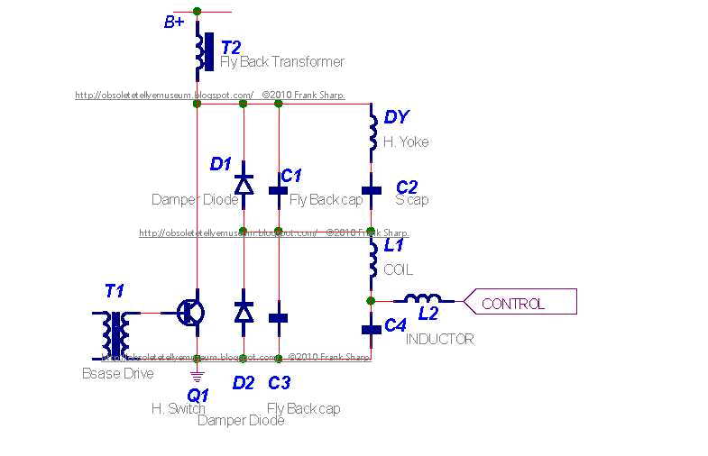
SPLIT DIODE MODULATOR
This horizontal circuit consists of two parts. D1, C1, C2 and DY are the components as described above.
D2, C3, C4 and L1 are a second “dummy” horizontal section that does not cause deflection current. By the
D.C. analyzing this circuit the voltage across C2 + C4 must equal the supply voltage (B+). Deflection
current in the DY is related to the supply voltage minus the voltage across C4. For a maximum horizontal
size the control point must be held at ground. This causes the dummy section to not operate and the DY
section will get full supply voltage. If the control point is at 1/3 supply then the DY section will be
operating at 2/3 supply.
Note: The impedance of (D1,C1,C2 and DY) and (D2,C3,C4 and L1) makes a voltage divider. If the
control point is not connected then there is some natural voltage on C4. Most split diode monitors are built
to pull power from the dummy section through L2 to ground. A single power transistor shunts from the
control point to ground. It is true that power can be supplied from some other supply through L2 to rise the voltage on C4. For maximum range a bi-directional power amplifier can drive the control point.
The most exciting feature if the split diode modulator is that the flyback pulse, as seen by the flyback
transformer, is the same size at all horizontal size settings.


HORIZONTAL SWITCH/DAMPER DIODE
On the right hand side of the screen, the H. switch transistor conducts current through the deflection yoke.
This current comes from the S correction capacitors, which have a charge equal to the effective supply
voltage. The damper diode allows current for the left hand side of the screen to flow back through the
deflection yoke to the S capacitors.
FLYBACK CAPACITOR
The flyback capacitor connects the hot side of the yoke to ground. This component determines the size and
length of the flyback pulse. ‘Tuning the flyback capacitor’ is done to match the timing of the flyback pulse
to the video blanking time of the video signal. The peak flyback voltage on the horizontal switch must be
set to less that 80% if the Vces specification. The two conditions of time and voltage can be set by three
variables (supply voltage, retrace capacitor and yoke inductance) .
S CAPACITOR
The S capacitors corrects outside versus center linearity in the horizontal scan. The voltage on the S cap
has a parabola plus the DC horizontal supply. Reducing the value of S cap increases this parabola thus
reducing the size of the outside characters and increasing the size of the center characters.
S Capacitor value: Too low: picture will be squashed towards edges.
Too high: picture will be stretched towards edges.

By simply putting a capacitor in series with each coil, the sawtooth waveform is
modified into a slightly sine-wave shape. This reduces the scanning speed near the
edges where the yoke is more sensitive. Generally the deflection angle of the electron
beam and the yoke current are closely related. The problem is the deflection angle
verses the distance of movement on the CRT screen does not have a linear effect.

BASE DRIVE CURRENT
The base drive resistor determines the amount of
base drive. If the transistor is over driven the Vsat
looks very good, but the current fall time is poor.
If the base current is too small the current fall time is very fast. The problem is that the transistor will have many volts across C-E when closed.
The best condition is found by placing the transistor in the heaviest load condition. Adjust the base resistor for the least power consumption then increase the base drive a small amount. This will slightly over drive the base.


BU208(A)

Silicon NPN
npn transistors,pnp transistors,transistors
Category: NPN Transistor, Transistor
MHz: <1 MHz
Amps: 5A
Volts: 1500V
HIGH VOLTAGE CAPABILITY
JEDEC TO-3 METAL CASE.

DESCRIPTION
The BU208A, BU508A and BU508AFI are
manufactured using Multiepitaxial Mesa
technology for cost-effective high performance
and use a Hollow Emitter structure to enhance
switching speeds.

APPLICATIONS:
* HORIZONTAL DEFLECTION FOR COLOUR TV With 110° or even 90° degree of deflection angle.

ABSOLUTE MAXIMUM RATINGS
Symbol Parameter Value Unit
VCES Collector-Emit ter Voltage (VBE = 0) 1500 V
VCEO Collector-Emit ter Voltage (IB = 0) 700 V
VEBO Emitter-Base Voltage (IC = 0) 10 V
IC Collector Current 8 A
ICM Collector Peak Current (tp < 5 ms) 15 A
TO - 3 TO - 218 ISOWATT218
Ptot Total Dissipation at Tc = 25 oC 150 125 50 W
Tstg Storage Temperature -65 to 175 -65 to 150 -65 to 150 oC
Tj Max. Operating Junction Temperature 175 150 150 °C