


The PHILIPS 26C566 /38Z is A heavy and big 26 inches color television from PHILIPS.
First set and PHILIPS model series introducing the InLine PHILIPS 20AX CRT TUBE FAMILY with PHILIPS K11 CHASSIS.The PHILIPS 20AX system was introduced in Europe as the first self converging picture tube/deflection coil, combination for 110° degree deflection and screen sizes up to 26". The system is based on the automatic convergence principle discovered by Haantjes and Lubben of Philips Research Laboratory more than 20 years ago. It makes use of an in-line gun array in conjunction with a specially designed saddle type deflection coil. Residual small tolerance errors are compensated by a simple dynamic four-pole system. The tube is 2 cm shorter than conventional 110° Degree tubes and has a standard 36.5 mm neck in order to obtain good color selection. A slotted mask is used in combination with a stripe-structure screen. Picture sharpness is ensured by an astigmatic electron gun.
 main
features are the use of three guns mounted horizontally in line, the
use of a shadow - mask with slots instead of circular holes, and a
screen with the phosphors deposited in vertical stripes instead of as a
pattern of dot triads. It seems therefore that the days of the present
delta gun shadowmask tube are now numbered, though considerable
production will have to continue for many years to provide replacement
tubes for the millions of colour sets already in use. So far as the
viewer is concerned however it is important to appreciate the time scale
involved (see above) and the reasons for the development of the new
tube. There is nothing wrong with the type of shadow - mask tube we have
known since the beginning of colour TV: it is able to provide superb
pictures. But in its 110° form it does require rather a lot of
scan/convergence correction circuitry. If this can be reduced by means
of an alternative approach
main
features are the use of three guns mounted horizontally in line, the
use of a shadow - mask with slots instead of circular holes, and a
screen with the phosphors deposited in vertical stripes instead of as a
pattern of dot triads. It seems therefore that the days of the present
delta gun shadowmask tube are now numbered, though considerable
production will have to continue for many years to provide replacement
tubes for the millions of colour sets already in use. So far as the
viewer is concerned however it is important to appreciate the time scale
involved (see above) and the reasons for the development of the new
tube. There is nothing wrong with the type of shadow - mask tube we have
known since the beginning of colour TV: it is able to provide superb
pictures. But in its 110° form it does require rather a lot of
scan/convergence correction circuitry. If this can be reduced by means
of an alternative approach gned
with the tube. And thirdly it is a thick neck tube. Unlike the PI tube
in which all the gun electrodes except the cathodes are common to all
guns the electrodes of each gun in the 20AX are separately available at
the base. This means that in addition to RGB drive to the cathodes the
grids are available for blanking and beam limiting and the first anodes
for background control setting in the normal manner. In fact PHILIPS
emphasised that the new tube is entirely compatible with existing colour
set techniques though the whole convergence system is greatly
simplified. The basic idea behind these in line gun, slotted mask tubes
is that by mounting the guns horizontally in line the convergence errors
are confined to the horizontal plane and by applying an astigmatic
deflection field these errors are cancelled. This means that a fair
amount of cunning in the design of the deflection yoke is required. A
saddlewound yoke is more efficient than a toroidal yoke since the
deflection fields are totally enclosed.
gned
with the tube. And thirdly it is a thick neck tube. Unlike the PI tube
in which all the gun electrodes except the cathodes are common to all
guns the electrodes of each gun in the 20AX are separately available at
the base. This means that in addition to RGB drive to the cathodes the
grids are available for blanking and beam limiting and the first anodes
for background control setting in the normal manner. In fact PHILIPS
emphasised that the new tube is entirely compatible with existing colour
set techniques though the whole convergence system is greatly
simplified. The basic idea behind these in line gun, slotted mask tubes
is that by mounting the guns horizontally in line the convergence errors
are confined to the horizontal plane and by applying an astigmatic
deflection field these errors are cancelled. This means that a fair
amount of cunning in the design of the deflection yoke is required. A
saddlewound yoke is more efficient than a toroidal yoke since the
deflection fields are totally enclosed.In comparison to current 110° PHILIPS tubes the 20AX requires much the same horizontal deflection power but about twice the vertical deflection power (which can be obtained without trouble from modern semiconductor devices). The use of a separate yoke with a tube of this type means that some dynamic convergence controls are still necessary, in order to match the assemblies. PHILIPS refer to these as "tolerance adjustments" rather than "dynamic convergence controls". About seven are required at present though further work is being done on this and by the time sets with the new tube appear we can expect some reduction. A single pincushion transductor is required instead of the two needed with 110° shadowmask tubes of the present variety. In comparison the PIL tube requires no dynamic convergence adjustments, only some simple tube neck magnets for static setting up. It is a little less efficient however because of the type of yoke employed. Whatever else happens there is no doubt that the vast majority of colour tubes fitted to TVC sets come 1977 will be of the in line gun, slotted mask, vertical phosphor stripe variety. Two further points made by PHILIPS at their demonstration : first, this type of tube requires less degaussing so that there are worthwhile savings in the amount of copper required for the degaussing coils: secondly their new tube, and in fact all PHILIPS monochrome tubes and shortly their colour tubes as well, will incorporate "instant on" guns which come into operation about five seconds after the set is switched on instead of the 30 seconds or more taken by present tubes. This instant on feature is based on a new heater/cathode assembly in which the use of mica insulators has been avoided.

Meanwhile we understand that in addition to RCA and, in the UK, Mazda, ITT and Videocolor SA are to produce PIL tubes. Whilst congratulations all round was appropriate on the successful development of these tubes it does seem a pity that was about to enter for the first time an era of non compatible colour c.r.t.s.
All previous models are using DELTA CRT TUBES.
It has 12 programs preselection with touch sensoric keyboard on front and Ultrasonic remote feature , for that is even a first model series with PHILIPS CHASSIS K11 with remote control feature.
A big led display on top near power switch is present.
Search tuning is performed in drawers with 6 + 6 program potentiometers.
For each program the tuning has to be made until reaching the desired station.
The mechanical turret approach to television tuning has been used almost exclusively for the past 60 years. Even though replete with the inherent disadvantages of mechanical complexity, unreliability and cost, such apparatus has been technically capable of performing its intended function and as a result the consumer has had to bear the burdens associated with the device. However, with the " recent " Broadcast demands for parity of tuning for UHF and VHF channels, the increasing number of UHF and cable TV stations have imposed new tuning performance requirements which severely tax the capability of the mechanical turret tuner. Consequently, attempts are now being made to provide all electronic tuning to meet the new requirements.
One " " new " " tuning system currently being incorporated in some television receivers uses a varactor tuner which overcomes some of the disadvantages of mechanical turret tuner by accomplishing tuning electronically. As the name indicates, the heart of such a tuner is a varactor diode which is used as a capacitive tuning element in the RF and local oscillator sections. In this system, channel selection is
made
by applying a given reverse bias voltage to the varactor to change its
electrical capacitance. The channel selection biasing can be performed
by mechanically or electrically switching approximately 5 or many more
preset potentiometers. The invention relates to a tuning unit with bandswitch for high frequency receivers, especially radio and television receivers, having a potentiometer system for the control of capacity diodes, the said potentiometer system consisting of a plurality of parallel resistance paths along which wiper contacts can be driven by means of screw spindles disposed adjacent one another in a common insulating material housing in which a bandswitch formed of metal rods is associated with each tuning spindle.
In these tuning units, the working voltages of the capacity diodes in the tuning circuits are recorded once a precise tuning to the desired frequency has been performed. A potentiometer tuning system has great advantages over the formerly used channel selectors operating with mechanically adjustable capacitors (tuning condensers) or mechanically adjustable inductances (variometers), mainly because it is not required to have such great precision in its tuning mechanism.
 Tuning units with bandswitches
formed of variable resistances and combined with interlocking
pushbuttons controlling the supply of recorded working voltages to
capacity diodes are known. It has a sensor keyboard for local commands, includes a plurality of
tuning positions each defined by an adjustable potentiometer, a neon
bulb indicator, a UHF/VHF switch and a two pole momentary contact
touch switch. A common tuning capacitor has a tuning voltage developed
thereacross for controlling the tuning of a varactor diode tuner. A
source of reference potential is coupled across the tuning
potentiometers and closure of any touch switch results in the tuning
capacitor being charged from the voltage reference source through the
selected one of the tuning potentiometers. The neon bulbs yield a
visual indication of the selected tuning position. Circuitry for
automatically placing control of the tuner to a preselected one of the
tuning positions upon turn on of the receiver is also included.A
solid-state voltage-controlled capacitor (varactor or varicap) UHF
television tuner is described which includes a varicap preselector tuned
circuit, a varicap tuned RF amplifier stage inductively coupled to the
preselector circuit, and a varicap tuned oscillator stage, both the
oscillator stage and the amplifier stage being inductively coupled to
the diode mixer stage from which an IF signal is derived. The tuners
employs a single tuning voltage source to tune across the entire UHF
range and also includes provision for AGC. Trimmer capacitors and
inductance adjusting devices of unique and advantageous configuration
are employed to align the tuner. Further disclosed are unique methods of
assembly and alignment for the tuner. The resistances serving as voltage dividers in these
tuning units are combined into a component unit such that they are in
the form of a ladderlike pattern on a common insulating plate forming
the cover of the housing in which the tuning spindles and wiper contacts
corresponding to the variable resistances are housed. The number of
resistances corresponds to the number of channels or frequencies which
are to be recorded. The wiper contact picks up a voltage which, when
applied to the capacity diodes determines their capacitance and hence
the frequency of the corresponding oscillating circuit. The adjustment
of the wipers is performed by turning the tuning spindle coupled to the
tuning knob. By the depression of a button the electrical connection
between a contact rod and a tuning spindle is brought about and thus the
selected voltage is applied to the capacity diodes. Since the push
buttons release one another, it is possible simply by depressing another
button to tune to a different receiving frequency or a different
channel, as the case may be.
Tuning units with bandswitches
formed of variable resistances and combined with interlocking
pushbuttons controlling the supply of recorded working voltages to
capacity diodes are known. It has a sensor keyboard for local commands, includes a plurality of
tuning positions each defined by an adjustable potentiometer, a neon
bulb indicator, a UHF/VHF switch and a two pole momentary contact
touch switch. A common tuning capacitor has a tuning voltage developed
thereacross for controlling the tuning of a varactor diode tuner. A
source of reference potential is coupled across the tuning
potentiometers and closure of any touch switch results in the tuning
capacitor being charged from the voltage reference source through the
selected one of the tuning potentiometers. The neon bulbs yield a
visual indication of the selected tuning position. Circuitry for
automatically placing control of the tuner to a preselected one of the
tuning positions upon turn on of the receiver is also included.A
solid-state voltage-controlled capacitor (varactor or varicap) UHF
television tuner is described which includes a varicap preselector tuned
circuit, a varicap tuned RF amplifier stage inductively coupled to the
preselector circuit, and a varicap tuned oscillator stage, both the
oscillator stage and the amplifier stage being inductively coupled to
the diode mixer stage from which an IF signal is derived. The tuners
employs a single tuning voltage source to tune across the entire UHF
range and also includes provision for AGC. Trimmer capacitors and
inductance adjusting devices of unique and advantageous configuration
are employed to align the tuner. Further disclosed are unique methods of
assembly and alignment for the tuner. The resistances serving as voltage dividers in these
tuning units are combined into a component unit such that they are in
the form of a ladderlike pattern on a common insulating plate forming
the cover of the housing in which the tuning spindles and wiper contacts
corresponding to the variable resistances are housed. The number of
resistances corresponds to the number of channels or frequencies which
are to be recorded. The wiper contact picks up a voltage which, when
applied to the capacity diodes determines their capacitance and hence
the frequency of the corresponding oscillating circuit. The adjustment
of the wipers is performed by turning the tuning spindle coupled to the
tuning knob. By the depression of a button the electrical connection
between a contact rod and a tuning spindle is brought about and thus the
selected voltage is applied to the capacity diodes. Since the push
buttons release one another, it is possible simply by depressing another
button to tune to a different receiving frequency or a different
channel, as the case may be. The problem with such arrangement is that it quite seriously limits the number of channels available to the consumer. Additionally, it suffers from the drawback that all potentiometers require adjusting for the desired channels. The VHF channels are usually factory adjusted while the six UHF channels require on-location adjustment. Moreover, using this arrangement, the only indication--during adjustment--of which channel is selected is by station identification.
All other controls are performed manually.
The set here in collection has an hughe count of hours (near 85000) of power up (was an all day powered set), but still functional with good pictures.
The set is build with a Modular chassis design because as modern television receivers become more complex the problem of
repairing the receiver becomes more difficult. As the number of
components used in the television receiver increases the susceptibility
to breakdown increases and it becomes more difficult to replace
defective components as they are more closely spaced. The problem has
become even more complicated with the increasing number of color
television receivers in use. A color television receiver has a larger
number of circuits of a higher degree of complexity than the black and
white receiver and further a more highly trained serviceman is required
to properly service the color television receiver.
Fortunately
for the service problem to date, most failures occur in the vacuum tubes
used in the television receivers. A faulty or inoperative vacuum tube
is relatively easy to find and replace. However, where the television
receiver malfunction is caused by the failure of other components, such
as resistors, capacitors or inductors, it is harder to isolate the
defective component and a higher degree of skill on the part of the
serviceman is required.
Even with the great majority of the
color television receiver malfunctions being of the "easy to find and
repair" type proper servicing of color sets has been difficult to obtain
due to the shortage of trained serviceman.
At the present time
advances in the state of the semiconductor art have led to the
increasing use of transistors in color television receivers. The
receiver described in this application has only two tubes, the picture
tube and the high voltage rectifier tube, all the other active
components in the receiver being semiconductors.
One important
characteristic of a semiconductor device is its extreme reliability in
comparison with the vacuum tube. The number of transistor and integrated
circuit failures in the television receiver will be very low in
comparison with the failures of other components, the reverse of what is
true in present day color television receivers. Thus most failures in
future television receivers will be of the hard to service type and will
require more highly qualified servicemen.
The primary symptoms
of a television receiver malfunction are shown on the picture tube of
the television receiver while the components causing the malfunction are
located within the cabinet. Also many adjustments to the receiver
require the serviceman to observe the screen. Thus the serviceman must
use unsatisfactory mirror arrangements to remove the electronic chassis
from the cabinet, usually a very difficult task. Further many components
are "buried" in a maze of circuitry and other components so that they
are difficult to remove and replace without damage to other components
in the receiver.
Repairing a modern color television receiver
often requires that the receiver be removed from the home and carried to
a repair shop where it may remain for many weeks. This is an expensive
undertaking since most receivers are bulky and heavy enough to require
at least two persons to carry them. Further, two trips must be made to
the home, one to pick up the receiver and one to deliver it. For these
reasons, the cost of maintaining the color television receiver in
operating condition often exceeds the initial cost of the receiver and
is an important factor in determining whether a receiver will be
purchased.
Therefore, the object of this invention is to provide a transistorized
color television receiver in which the main electronic chassis is easily
accessible for maintenance and adjustment. Another object of this invention is to provide a transistorized color
television receiver in which the electronic circuits are divided into a
plurality of modules with the modules easily removable for service and
maintenance. The main electronic chassis is slidably mounted within the
cabinet so
that it may be withdrawn, in the same manner
as a drawer, to expose the electronic circuitry therein for maintenance
and adjustment from the rear closure panel after easy removal. Another
aspect is the capability to be serviced at eventually the home of the
owner.
Still an example of Evelasting tellye.
IMPORTANT NOTE FOR PHILIPS K9 / K11 CHASSIS SETS:
Devices with the K9 chassis (delta picture tube) and the successors with the K9i to K11 chassis (in-line picture tube) are rightly considered to be very reliable and durable.
However, there is a very important warning:
In Philips Chassis K9 sets, two parallel-connected flyback capacitors are used in the line output stage, in contrast to the usual at the time circuit technology. These capacitors are arranged parallel to the line output stage transistor (here are two BU109s connected in parallel), one on the circuit board, the other directly next to the transistors.
Unfortunately, the problem is the quality of these capacitors (make ERO)! Most of the time, one fails after a short period of operation due to a total loss of capacity.
What follows is like a total catastrofic failure:
The failed capacitor reduces the return capacity from approx. 10nF to approx. 5nF or lower because the resonance of the circuit will be altered. This increases by consequence the high voltage (UHT/EHT) from 25kV to over 40kV !!! This makes the picture very bright, razor sharp and much too small.Also X-RAYS are developed !!!!!!!!
There is great danger! The device must be switched off immediately!
Reason: In spite of the far too high return voltage, experience shows that the very stable BU transistors do not die, and strangely enough, this usually withstands the high-voltage cascade; the high voltage generation goes on instead of ending itself. Rather, the high voltage inside the neck of the picture tube (in the area of the focus) then strikes very quickly through the glass to the outside into the convergence or deflection unit.
This leads to considerable damage:The picture tube draws air, the filament burns through, the color difference output stages break through, the convergence circuits are affected, etc., etc. Usually this is the economic end of such devices.
It is a series error that Philips was aware of at the time and that Philips had made known to the workshops. Unfortunately, the two ERO capacitors were often not replaced by a single, low-loss (!) 2kV capacitor (mostly Röderstein KP, blue) as a precaution, as prescribed, so that unfortunately quite a few of these devices literally "blown up".
That is why I urgently mandatory recommend that you always check with these devices whether the old ERO capacitors have been replaced by a single, suitable capacitor! To be on the safe side, the chassis K9i to K11 were also used, although these usually only had one capacitor installed as standard, a green one.
List of sets known to have the K11 chassis (made from approximately 1975-1978)
= means that models are most likely the same or very similar, but the styling can be different in some cases. Information was amongst others taken from the Philips model number survey 2003, 3122 785 14570.
A side note for those who have noticed the K10 chassis is missing from the line up. Rumour has, that this was a K9 variant with another tube, probably Trinitron, that didn’t make it beyond the prototype stage. Instead, Philips decided to use the 20AX tube and named the chassis K11. This chassis was designated K9i in some countries, most notable Germany. The differences between the K9 and K11 chassis were probably thought of as minor as the K11 chassis was basically an improved version of the K9 chassis with some minor (evolutionary) updates, another tube and as a result less complicated convergence circuits.
General models
22C545
22C549
26C364
26C466
26C555
26C556
26C557
26C560
26C561
26C564
26C565
26C566
26C567
26C568
26C569
26C655
26C657
26C663
26C667
26C677
26C750
26C752
26C753
26C762
26C764
26C768
26C770
26C782
26C840
Germany
Factory location Krefeld (KR)
It seems very strange that only one German model is mentioned. Quite possibly the person who compiled the official Philips model number survey got confused by the K9i nomenclature. As a result of that, the D26C865 mentioned in the K9 overview might actually be a K11 set. Other German K11 sets probably exist.
D26C662
D26C865??
Sweden
Factory location Norrköping (NF)
SK22C462
SK26C464
SK26C466
SK26C467
SK26C468
SK26C476
SK26C477
SK26C478
SK26C764
SK26C765
SK26C773
SK26C776
SK26C777
SK26C778
SK26C865
South Africa
Factory location Martinsville
V26k606
V26K609
Other brands (Erres, possibly Schneider (F), ..)
Erres branded sets mostly used the prefix RS
The suffix KSK instead of K might indicate a Swedish model. I haven’t actually seen it on a set in person.
22264KSK
22545K = 22C545
26555K
26557K
26565K
26566K
26568K
26655K
26756K
26764KSK
26768K
26965KSK
26966KSK
263637K
263737K
Other Brands
As a rule, the model number below is prefixed by letters indicating the brand name as
follows (not all brands may be used, others may exist):
AR = Aristona
SA = Siera
RA = Radiola
DX = Dux
CT = Conserton?
The infix KSK instead of K might indicate a Swedish model. I haven’t actually seen it on a set in person.
56KSK264
56K545 = 22C545
56K549 = 22C549
26K0624 (?)
66KSK364
66KSK365
66KSK366
66KSK375
66KSK376
66K466
66K555
66K557
66K565
66K566
66K568
66K655
66K756
66KSK764
66K768
66K4627
66K4727
66K5520
66K5522
66K5624
PROGRESSIVE BY YEAR LIST OF COLOR TELEVISION SETS WITH PHILIPS CHASSIS K11 20AX CRT TUBE.
26C466 CHASSIS K11 YEAR 1974
26565K CHASSIS K11 YEAR 1975
26566K CHASSIS K11 YEAR 1975
26C567 CHASSIS K11 YEAR 1975
66K565 CHASSIS K11 YEAR 1975
66K566 CHASSIS K11 YEAR 1975
22264KSK CHASSIS K11 YEAR 1976
22545K CHASSIS K11 YEAR 1976
22C545 CHASSIS K11 YEAR 1976
22C549 CHASSIS K11 YEAR 1976
26555K CHASSIS K11 YEAR 1976
26557K CHASSIS K11 YEAR 1976
26568K CHASSIS K11 YEAR 1976
26655K CHASSIS K11 YEAR 1976
26756K CHASSIS K11 YEAR 1976
26764KSK CHASSIS K11 YEAR 1976
26966KSK CHASSIS K11 YEAR 1976
26C555 CHASSIS K11 YEAR 1976
26C557 CHASSIS K11 YEAR 1976
26C565 CHASSIS K11 YEAR 1976
26C566 CHASSIS K11 YEAR 1976
26C568 CHASSIS K11 YEAR 1976
26C569 CHASSIS K11 YEAR 1976
26C655 CHASSIS K11 YEAR 1976
56K545 CHASSIS K11 YEAR 1976
56K549 CHASSIS K11 YEAR 1976
56KSK264 CHASSIS K11 YEAR 1976
66K555 CHASSIS K11 YEAR 1976
66K557 CHASSIS K11 YEAR 1976
66K568 CHASSIS K11 YEAR 1976
66K655 CHASSIS K11 YEAR 1976
66K756 CHASSIS K11 YEAR 1976
66KSK365 CHASSIS K11 YEAR 1976
66KSK366 CHASSIS K11 YEAR 1976
SK22C462 CHASSIS K11 YEAR 1976
SK26C464 CHASSIS K11 YEAR 1976
SK26C466 CHASSIS K11 YEAR 1976
SK26C467 CHASSIS K11 YEAR 1976
SK26C765 CHASSIS K11 YEAR 1976
sk26c865 CHASSIS K11 YEAR 1976
V26K606 CHASSIS K11 YEAR 1976
V26K609 CHASSIS K11 YEAR 1976
263637K CHASSIS K11 YEAR 1977
26768K CHASSIS K11 YEAR 1977
26C364 CHASSIS K11 YEAR 1977
26C556 CHASSIS K11 YEAR 1977
26C564 CHASSIS K11 YEAR 1977
26C657 CHASSIS K11 YEAR 1977
26C667 CHASSIS K11 YEAR 1977
26C677 CHASSIS K11 YEAR 1977
26C762 CHASSIS K11 YEAR 1977
26C764 CHASSIS K11 YEAR 1977
26C768 CHASSIS K11 YEAR 1977
26C770 CHASSIS K11 YEAR 1977
26C782 CHASSIS K11 YEAR 1977
56K0624 CHASSIS K11 YEAR 1977
66K4627 CHASSIS K11 YEAR 1977
66K5624 CHASSIS K11-TRIPLER YEAR 1977
66K768 CHASSIS K11 YEAR 1977
66KSK375 CHASSIS K11 YEAR 1977
66KSK376 CHASSIS K11 YEAR 1977
66KSK764 CHASSIS K11 YEAR 1977
SK26C468 CHASSIS K11 YEAR 1977
SK26C476 CHASSIS K11 YEAR 1977
SK26C478 CHASSIS K11 YEAR 1977
SK26C764 CHASSIS K11 YEAR 1977
SK26C773 CHASSIS K11 YEAR 1977
SK26C776 CHASSIS K11 YEAR 1977
SK26C777 CHASSIS K11 YEAR 1977
263737K CHASSIS K11 YEAR 1978
26965KSK CHASSIS K11 YEAR 1978
26C560 CHASSIS K11 YEAR 1978
26C561 CHASSIS K11 YEAR 1978
26C663 CHASSIS K11 YEAR 1978
26C750 CHASSIS K11 YEAR 1978
26C752 CHASSIS K11 YEAR 1978
26C753 CHASSIS K11 YEAR 1978
26C840 CHASSIS K11 YEAR 1978
66K466 CHASSIS K11 YEAR 1978
66K4727 CHASSIS K11 YEAR 1978
66K5520 CHASSIS K11 YEAR 1978
66K5522 CHASSIS K11 YEAR 1978
66KSK364 CHASSIS K11 YEAR 1978
D26C662 CHASSIS K11 YEAR 1978
SK26C477 CHASSIS K11 YEAR 1978
SK26C778 CHASSIS K11 YEAR 1978
Koninklijke Philips Electronics N.V. (Royal Philips Electronics Inc.), most commonly known as Philips, (Euronext: PHIA, NYSE: PHG) is a multinational Dutch electronics corporation.

Philips is organized in a number of sectors: Philips Consumer Lifestyles (formerly Philips Consumer Electronics and Philips Domestic Appliances and Personal Care), Philips Lighting and Philips Healthcare (formerly Philips Medical Systems).
The company was founded in 1891 by Gerard Philips, a maternal cousin of Karl Marx, in Eindhoven, Netherlands. Its first products were light bulbs and other electro-technical equipment. Its first factory survives as a museum devoted to light sculpture. In the 1920s, the company started to manufacture other products, such as vacuum tubes (also known worldwide as 'valves'), In 1927 they acquired the British electronic valve manufacturers Mullard and in 1932 the German tube manufacturer Valvo, both of which became subsidiaries. In 1939 they introduced their electric razor, the Philishave (marketed in the USA using the Norelco brand name).
Philips was also instrumental in the revival of the Stirling engine.
As a chip maker, Philips Semiconductors was among the Worldwide Top 20 Semiconductor Sales Leaders.

In December 2005 Philips announced its intention to make the Semiconductor Division into a separate legal entity. This process of "disentanglement" was completed on 1 October 2006.
On 2 August 2006, Philips completed an agreement to sell a controlling 80.1% stake in Philips Semiconductors to a consortium of private equity investors consisting of Kohlberg Kravis Roberts & Co. (KKR), Silver Lake Partners and AlpInvest Partners. The sale completed a process, which began December 2005, with its decision to create a separate legal entity for Semiconductors and to pursue all strategic options. Six weeks before, ahead of its online dialogue, through a letter to 8,000 of Philips managers, it was announced that they were speeding up the transformation of Semiconductors into a stand-alone entity with majority ownership by a third party. It was stated then that "this is much more than just a transaction: it is probably the most significant milestone on a long journey of change for Philips and the beginning of a new chapter for everyone – especially those involved with Semiconductors".
In its more than 115 year history, this co
 unts
as a big step that is definitely changing the profile of the company.
Philips was one of few companies that successfully made the
transition from the electrical world of the 19th century into the
electronic age, starting its semiconductor activity in 1953 and
building it into a global top 10 player in its industry. As such,
Semiconductors was at the heart of many innovations in Philips over
the past 50 years.
unts
as a big step that is definitely changing the profile of the company.
Philips was one of few companies that successfully made the
transition from the electrical world of the 19th century into the
electronic age, starting its semiconductor activity in 1953 and
building it into a global top 10 player in its industry. As such,
Semiconductors was at the heart of many innovations in Philips over
the past 50 years.Agreeing to start a process that would ultimately lead to the decision to sell the Semiconductor Division therefore was one of the toughest decisions that the Board of Management ever had to make.
On 21 August 2006, Bain Capital and Apax Partners announced that they had signed definitive commitments to join the expanded consortium headed by KKR that is to acquire the controlling stake in the Semiconductors Division.
On 1 September 2006, it was announced in Berlin that the name of the new semiconductor company founded by Philips is NXP Semiconductors.
Coinciding with the sale of the Semiconductor Division, Philips also announced that they would drop the word 'Electronics' from the company name, thus becoming simply Koninklijke Philips N.V. (Royal Philips N.V.).
 The
foundations of Philips were laid in 1891 when Anton and Gerard Philips
established Philips & Co. in Eindhoven, the Netherlands. The
company begun manufacturing carbon-filament lamps and by the turn of
the century, had become one of the largest producers in Europe.
Stimulated by the industrial revolution in Europe, Philips’ first
research laboratory started introducing its first innovations in the
x-ray and radio technology. Over the years, the list of inventions has
only been growing to include many breakthroughs that have continued to
enrich people’s everyday lives.
The
foundations of Philips were laid in 1891 when Anton and Gerard Philips
established Philips & Co. in Eindhoven, the Netherlands. The
company begun manufacturing carbon-filament lamps and by the turn of
the century, had become one of the largest producers in Europe.
Stimulated by the industrial revolution in Europe, Philips’ first
research laboratory started introducing its first innovations in the
x-ray and radio technology. Over the years, the list of inventions has
only been growing to include many breakthroughs that have continued to
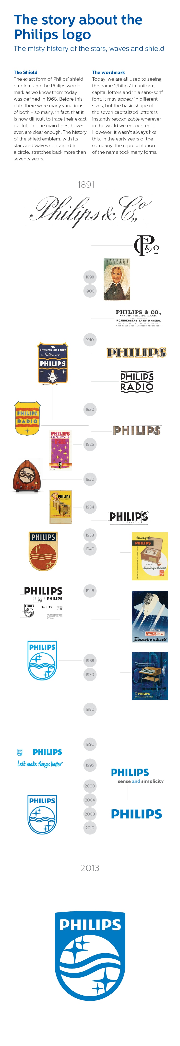
enrich people’s everyday lives.In the early years of Philips &; Co., the representation of the company name took many forms: one was an emblem formed by the initial letters of Philips ; Co., and another was the word Philips printed on the glass of metal filament lamps.
One of the very first campaigns was launched in 1898 when Anton Philips used a range of postcards showing the Dutch national costumes as marketing tools. Each letter of the word Philips was printed in a row of light bulbs as at the top of every card. In the late 1920s, the Philips name began to take on the form that we recognize today.
The now familiar Philips waves and stars first appeared in 1926 on the packaging of miniwatt radio valves, as well as on the Philigraph, an early sound recording device. The waves symbolized radio waves, while the stars represented the ether of the evening sky through which the radio waves would travel.
In 1930 it was the first time that the four stars flanking the three waves were placed together in a circle. After that, the
stars and waves started appearing on radios and gramophones, featuring
this circle as part of their design. Gradually the use of the circle
emblem was then extended to advertising materials and other products.At this time Philips’ business activities were expanding rapidly and the company wanted to find a trademark that would uniquely represent Philips, but one that would also avoid legal problems with the owners of other well-known circular emblems. This wish resulted in the combination of the Philips circle and the wordmark within the shield emblem.
In 1938, the Philips shield made its first appearance. Although modified over the years, the basic design has remained constant ever since and, together with the wordmark, gives Philips the distinctive identity that is still embraced today.
The first steps of CRT production by Philips started in the thirties with the Deutsche Philips Electro-Spezial gesellschaft in Germany and the Philips NatLab (Physics laboratory) in Holland. After the introduction of television in Europe, just after WWII there was a growing demand of television sets and oscilloscope equipment. Philips in Holland was ambitious and started experimental television in 1948. Philips wanted to be the biggest on this market. From 1948 there was a small Philips production of television and oscilloscope tubes in the town of Eindhoven which soon developed in mass production. In 1976 a part of the Philips CRT production went to the town of Heerlen and produced its 500.000'th tube in 1986. In 1994 the company in Heerlen changed from Philips into CRT-Heerlen B.V. specialized in the production of small monochrome CRT's for the professional market and reached 1.000.000 produced tubes in 1996. In this stage the company was able to produce very complicated tubes like storage CRT's.
In 2001 the company merged into Professional Display Systems, PDS worked on LCD and Plasma technology but went bankrupt in 2009. The employees managed a start through as Cathode Ray Technology which now in 2012 has to close it's doors due to the lack of sales in a stressed market. Their main production was small CRT's for oscilloscope, radar and large medical use (X-ray displays). New experimental developments were small Electron Microscopy, 3D-TV displays, X-Ray purposes and Cathode Ray Lithography for wafer production. Unfortunately the time gap to develop these new products was too big.
28 of September 2012, Cathode Ray Technology (the Netherlands), the last Cathode Ray Tube factory in Europe closed. Ironically the company never experienced so much publicity as now, all of the media brought the news in Holland about the closure. In fact this means the end of mass production 115 years after Ferdinand Braun his invention. The rapid introduction and acceptation of LCD and Plasma displays was responsible for a drastic decrease in sales. Despite the replacement market for the next couple of years in the industrial, medical and avionics sector.
The numbers are small and the last few CRT producers worldwide are in heavy competition.
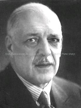
Gerard Philips:
 Gerard
Leonard Frederik Philips (October 9, 1858, in Zaltbommel – January 27,
1942, in The Hague, Netherlands) was a Dutch industrialist, co-founder
(with his father Frederik Philips) of the Philips Company as a family
business in 1891. Gerard and his younger brother Anton Philips changed
the business to a corporation by founding in 1912 the NV Philips'
Gloeilampenfabrieken. As the first CEO of the Philips corporation,
Gerard laid with Anton the base for the later Philips multinational.
Gerard
Leonard Frederik Philips (October 9, 1858, in Zaltbommel – January 27,
1942, in The Hague, Netherlands) was a Dutch industrialist, co-founder
(with his father Frederik Philips) of the Philips Company as a family
business in 1891. Gerard and his younger brother Anton Philips changed
the business to a corporation by founding in 1912 the NV Philips'
Gloeilampenfabrieken. As the first CEO of the Philips corporation,
Gerard laid with Anton the base for the later Philips multinational.Early life and education
Gerard was the first son of Benjamin Frederik David Philips (1 December 1830 – 12 June 1900) and Maria Heyligers (1836 – 1921). His father was active in the tobacco business and a banker at Zaltbommel in the Netherlands; he was a first cousin of Karl Marx.
Career
Gerard Philips became interested in electronics and engineering. Frederik was the financier for Gerard's purchase of the old factory building in Eindhoven where he established the first factory in 1891. They operated the Philips Company as a family business for more than a decade.
Marriage and family
On March 19, 1896 Philips married Johanna van der Willigen (30 September 1862 – 1942). They had no children.
Gerard was an uncle of Frits Philips, whom he and his brother brought into the business. Later they brought in his brother's grandson, Franz Otten.
Gerard and his brother Anton supported education and social programs in Eindhoven, including the Philips Sport Vereniging (Philips Sports Association), which they founded. From it the professional football (soccer) department developed into the independent Philips Sport Vereniging N.V.
Anton Philips:
 Anton
Frederik Philips (March 14, 1874, Zaltbommel, Gelderland – October 7,
1951, Eindhoven) co-founded Royal Philips Electronics N.V. in 1912 with
his older brother Gerard Philips in Eindhoven, the Netherlands. He
served as CEO of the company from 1922 to 1939.
Anton
Frederik Philips (March 14, 1874, Zaltbommel, Gelderland – October 7,
1951, Eindhoven) co-founded Royal Philips Electronics N.V. in 1912 with
his older brother Gerard Philips in Eindhoven, the Netherlands. He
served as CEO of the company from 1922 to 1939.Early life and education
Anton was born to Maria Heyligers (1836 – 1921) and Benjamin Frederik David Philips (December 1, 1830 – June 12, 1900). His father was active in the tobacco business and a banker at Zaltbommel in the Netherlands. (He was a first cousin to Karl Marx.) Anton's brother Gerard was 16 years older.
Career
In May 1891 the father Frederik was the financier and, with his son Gerard Philips, co-founder of the Philips Company as a family business. In 1912 Anton joined the firm, which they named Royal Philips Electronics N.V.
During World War I, Anton Philips managed to increas
e
sales by taking advantage of a boycott of German goods in several
countries. He provided the markets with alternative products.Anton (and his brother Gerard) are remembered as being civic-minded. In Eindhoven they supported education and social programs and facilities, such as the soccer department of the Philips Sports Association as the best-known example.
Anton Philips brought his son Frits Philips and grandson Franz Otten into the company in their times. Anton took the young Franz Otten with him and other family members to escape the Netherlands just before the Nazi Occupation during World War II; they went to the United States. They returned after the war.
His son Frits Philips chose to stay and manage the company during the occupation; he survived several months at the concentration camp of Vught after his workers went on strike. He saved the lives of 382 Jews by claiming them as indispensable to his factory, and thus helped them evade Nazi roundups and deportation to concentration camps.
Philips died in Eindhoven in 1951.
Marriage and family
Philips married Anne Henriëtte Elisabeth Maria de Jongh (Amersfoort, May 30, 1878 – Eindhoven, March 7, 1970). They had the following children:
* Anna Elisabeth Cornelia Philips (June 19, 1899 – ?), married in 1925 to Pieter Franciscus Sylvester Otten (1895 – 1969), and had:
o Diek Otten
o Franz Otten (b. c. 1928 - d. 1967), manager in the Dutch electronics company Philips
* Frederik Jacques Philips (1905-2005)
* Henriëtte Anna Philips (Eindhoven, October 26, 1906 – ?), married firstly to A. Knappert (d. 1932), without issue; married secondly to G. Jonkheer Sandberg (d. September 5, 1935), without issue; and married thirdly in New York City, New York, on September 29, 1938 to Jonkheer Gerrit van Riemsdijk (Aerdenhout, January 10, 1911 – Eindhoven, November 8, 2005). They had the following children:
o ..., Jonkheerin Gerrit van Riemsdijk (b. Waalre, October 2, 1939), married at Waalre on February 17, 1968 to Johannes Jasper Tuijt (b. Atjeh, Koeta Radja, March 10, 1930), son of Jacobus Tuijt and wife Hedwig Jager, without issue
o ..., Jonkheerin Gerrit van Riemsdijk (b. Waalre, April 3, 1946), married firstly at Calvados, Falaise, on June 6, 1974 to Martinus Jan Petrus Vermooten (Utrecht, September 16, 1939 – Falaise, August 29, 1978), son of Martinus Vermooten and wife Anna Pieternella Hendrika Kwantes, without issue; married secondly in Paris on December 12, 1981 to Jean Yves Louis Bedos (Calvados, Rémy, January 9, 1947 – Calvados, Lisieux, October 5, 1982), son of Georges Charles Bedos and wife Henriette Louise Piel, without issue; and married thirdly at Manche, Sartilly, on September 21, 1985 to Arnaud Evain (b. Ardennes, Sedan, July 7, 1952), son of Jean Claude Evain and wife Flore Halleux, without issue
o ..., Jonkheerin Gerrit van Riemsdijk (b. Waalre,
September 4, 1948), married at Waalre, October 28, 1972 to Elie Johan
François van Dissel (b. Eindhoven, October 9, 1948), son of Willem
Pieter(To see the Internal Chassis Just click on Older Post Button on bottom page, that's simple !)
A comment...........of a 1996 reality ..................
Philips, which seems to be a perennial walking wounded case. The company had appeared to be on the mend after a worldwide cost- cutting programme which was started five years ago when Jan Timmer took over as chairman.
But, following a sharp profits fall, with the company's first quarterly loss since 1992, a further shake up is being undertaken.
The difficulty is that the company operates in a mature market, in which prices are falling at an annual rate of six per cent. Manufacturers are competing by cutting costs to gain a larger share of static demand. It's not a situation in which any firm that does its own manufacturi
 This is an
approach that was pioneered many years ago by major Japanese
manufacturers. Rather than make everything yourself, you rely on
subcontractors who, in return, rely on you for their main source of
work. It is hardly a cosy arrangement: the whole point seems to be that
the major fain can exert pressure on its subcontractors, thereby - in
theory - achieving optimum efficiency and cost-effectiveness. What
happens when lower and lower prices are demanded for subcontracted work
is not made clear.
This is an
approach that was pioneered many years ago by major Japanese
manufacturers. Rather than make everything yourself, you rely on
subcontractors who, in return, rely on you for their main source of
work. It is hardly a cosy arrangement: the whole point seems to be that
the major fain can exert pressure on its subcontractors, thereby - in
theory - achieving optimum efficiency and cost-effectiveness. What
happens when lower and lower prices are demanded for subcontracted work
is not made clear. The whole edifice could collapse.
However that might be, this is the course on which Philips has now
embarked. The company is also to carry out distribution, sales and
marketing on a regional rather than a national basis, and has said that
it will not support Grundig's losses after this year.
The whole edifice could collapse.
However that might be, this is the course on which Philips has now
embarked. The company is also to carry out distribution, sales and
marketing on a regional rather than a national basis, and has said that
it will not support Grundig's losses after this year.But Philips' chief financial officer Dudley Eustace has said that it has "no intention of abandoning the television and audio business". One has to assume that the subcontracting will also be done on an international basis, as major Japanese firms have had to do. There is a sense of déjà vu about this, though one wishes Philips well - it is still one of the major contributors to research and development in our industry.
 Toshiba,
which has also just appointed a new top man, Taizo Nishimoro, provides
an interesting contrast. Mr Nishimoro thinks that the western emphasis
on sales and marketing rather than engineering is the way to go. So the
whole industry seems to be moving full circle. Taizo Nishimoro has
become the first non engineering president of Toshiba. Where the company
cannot compete effectively on its own, he intends to seek international
alliances or go for closures. He put it as follows. "The technology and the businesses we are engaged in are getting more complex.
Toshiba,
which has also just appointed a new top man, Taizo Nishimoro, provides
an interesting contrast. Mr Nishimoro thinks that the western emphasis
on sales and marketing rather than engineering is the way to go. So the
whole industry seems to be moving full circle. Taizo Nishimoro has
become the first non engineering president of Toshiba. Where the company
cannot compete effectively on its own, he intends to seek international
alliances or go for closures. He put it as follows. "The technology and the businesses we are engaged in are getting more complex.In these circumstances, if we try to do everything ourselves we are making a mistake." Here's how Minoru Makihara, who became head of Mitsubishi Corporation four years ago, sees it. "Technologies are now moving so fast that it is impossible for the top manager to know all the details.
Companies are now looking for generalists who can understand broad changes, delegate and provide leadership." Corporate change indeed amongst our oriental colleagues. Major firms the world over are facing similar problems and having to adopt similar policies.
In a mature market such as consumer electronics, you have to rely on marketing to squeeze the last little bit of advantage from such developments as Dolby sound and other added value features. The consumer electronics industry has been hoping that the digital video disc would come to its aid and get sales and profits moving ahead.

The other main use of the DVD is as a ROM in computer systems. For this application flexible copying facilities are a major requirement. But the movie companies are unwilling to agree to this. At present the situation is deadlocked and the great hope of an autumn launch, all important for sales, has had to be postponed. Next year maybe? It's a great pity, since the DVD has much to offer.
There's a lot of sad news on the retail side as well. Colorvision has been placed in administrative receivership in 1996 , with a threat to 800 jobs at its 76 stores, while the Rumbelows shops that were taken over by computer retailer Escom have suffered a similar fate. The receivers have closed down the UK chain with the loss of 850 jobs at some 150 stores. Nothing seems to be going right just now.
Publications
A. Heerding: The origin of the Dutch incandescent lamp industry. (Vol. 1 of The history of N.V. Philips gloeilampenfabriek). Cambridge, Cambridge University Press, 1986. ISBN 0-521-32169-7
A. Heerding: A company of many parts. (Vol. 2 of The history of N.V. Philips' gloeilampenfabrieken). Cambridge, Cambridge University Press, 1988. ISBN 0-521-32170-0
I.J. Blanken: The development of N.V. Philips' Gloeilampenfabrieken into a major electrical group. Zaltbommel, European Library, 1999. (Vol. 3 of The history of Philips Electronics N.V.). ISBN 90-288-1439-6
I.J. Blanken: Under German rule. Zaltbommel, European Library, 1999. (Vol. 4 of The history of Philips Electronics N.V). ISBN 90-288-1440-XReferences
"Philips Annual Report 2018". Philips Results. 27 February 2019. Retrieved 6 March 2019.
"Philips Greenpeace International". Greenpeace International. Archived from the original on 31 October 2010. Retrieved 7 January 2011.
"Philips Annual Report 2018 - Compare the previous 5 years". Philips Results. 27 February 2019. Retrieved 6 March 2019.
"Annual Report 2014". Philips. Retrieved 19 August 2012.
https://www.industryweek.com/global-economy/philips-drops-electronics-name-strategy-switch
"Börse Frankfurt (Frankfurt Stock Exchange): Stock market quotes, charts and news". Boerse-frankfurt.de. Retrieved 7 April 2018.
"Philips Museum". Philips-museum.com. Retrieved 30 December 2016.
C.M. Hargreaves (1991). The Philips Stirling Engine. Elsevier Science. ISBN 0-444-88463-7. pp.28–30
Philips Technical Review Vol.9 No.4 page 97 (1947)
C.M. Hargreaves (1991), Fig. 3
C.M. Hargreaves (1991), p.61
C.M. Hargreaves (1991), p.77
"Philips Electronics NV | Dutch manufacturer". Encyclopedia Britannica.
"BBC - WW2 People's War - Operation Oyster, Part 1". Bbc.co.uk. Retrieved 30 December 2016.
Everitt, Chris; Middlebrook, Martin (2 April 2014). "The Bomber Command War Diaries: An Operational Reference Book". Pen and Sword. Retrieved 30 December 2016 – via Google Books.
Bruce, Mr A I. "30th March 1943 WWII Timeline". Wehrmacht-history.com. Archived from the original on 12 February 2017. Retrieved 30 December 2016.
"Frits Philips celebrates 100th birthday". Philips. 15 April 2005. Retrieved 10 January 2015.
The Encyclopedia of the Righteous Among the Nations: Rescuers of Jews during the Holocaust: The Netherlands, Jerusalem: Yad Vashem, 2004, pp. 596–597
"PHILIPS Light Tower Complex - The Netherlands", Reynaers-solutions.com, Reynaers Aluminium, archived from the original on 20 January 2012, retrieved 12 September 2011
"Waarom stopt Philips met zelf televisies maken?". de Volkskrant. 18 April 2011. Retrieved 18 April 2011.
"BFI – Film & TV Database – The Philips Time Machine (1977)". The British Film Institute Web Database. Retrieved 16 February 2010.
Snow, Blake (5 May 2007). "The 10 Worst-Selling Consoles of All Time". GamePro.com. Archived from the original on 8 May 2007. Retrieved 1 November 2016.
https://www.trouw.nl/home/philips-gaat-aan-naam-eindelijk-het-woord-koninklijke-toevoegen~a0329b2a/
"Philips Completes Acquisition Agilent Technologies' Healthcare Solutions Group". Thefreelibrary.com. Retrieved 6 January 2017.
"Philips electronics to buy lifeline to expand in consumer health". Wsj.com. Retrieved 7 April 2018.
"Philips to Acquire Healthcare Informatics Company XIMIS Inc. to Strengthen Presence in the Healthcare Information Technology Market". Finanznachrichten.de. Retrieved 7 April 2018.
"News center - Philips". Arquivo.pt. Archived from the original on 16 May 2016. Retrieved 7 April 2018.
"Philips completes acquisition of US-based VISICU". Newscenter.philips.com. 21 February 2008. Retrieved 24 November 2012.
NRC Handelsblad, 4 September 2010 Het nieuwe Philips wordt blij van een iPad-hoesje/The new Philips becomes happy from an iPad cover, Dutch original:" 'We zijn geen high-tech bedrijf meer, het gaat erom dat de technologieën introduceren die breed gedragen worden door de consument', zegt Valk [..] Consumer Lifestyle is nu zodanig ingericht dat er geen jaren meer gewerkt wordt aan uitvindingen die weinig kans van slagen hebben. [..]De Philips staf windt er geen doekjes om dat het bedrijf niet altijd voorop loopt bij de technologische ontwikkelingen in consumentengoederen."
"Philips to merge Preethi biz in future". Moneycontrol.com. 5 September 2012. Retrieved 6 January2017.
"Sectra news and press releases - Sectra and Philips sign large mammography modality acquisition deal". Sectra.com. Archived from the original on 22 April 2016. Retrieved 8 April 2016.
"Philips to cut 4,500 jobs". The Guardian. 17 October 2011.
"Philips Electronics cuts another 2,200 jobs". Bbc.co.uk. 11 September 2012. Retrieved 7 April 2018.
Lezhnev, Sasha; Alex Hellmuth (August 2012). "Taking Conflict Out of Consumer Gadgets: Company Rankings on Conflict Minerals 2012" (PDF). Enough Project. Retrieved 17 August 2012.
"Philips, LG Electronics, 4 others fined 1.47 billion Euros for EU cartel". The Economic Times. 5 December 2012. Retrieved 5 December 2012.
Van, Robert. (29 January 2013) Philips Exits Consumer Electronics - The Source - WSJ. Blogs.wsj.com. Retrieved on 2013-08-16.
"Philips to exit hi-fis and DVD players". BBC News. 29 January 2013. Retrieved 2 February 2013.
"Philips exits shrinking home entertainment business". Reuters. 29 January 2013. Retrieved 2 February 2013.
Philips to take legal action against Funai. Broadbandtvnews.com (25 October 2013). Retrieved on 2013-12-09.
Sterling, Toby; Mari Yamaguchi. "Philips Breaks off Deal With Funai". ABC News. Amsterdam. Associated Press. Archived from the original on 2 November 2013. Retrieved 22 June 2014.
"Philips announces decision by ICC International Court of Arbitration in Funai arbitration case". Philips Electronics. 2016-04-26. Retrieved 2016-07-23.
"Paradox Engineering and Philips Lighting working together on smart city solutions". startupticker.ch. Retrieved on September 2013.
"Koninklijke Philips Electronics N.V.: Name change" (PDF). eurex. 15 May 2013. Retrieved 10 July 2013.
"Philips unveils new brand direction centered around innovation and people". Newscenter.philips.com. Retrieved 20 November 2013.
"Dutch electronics giant Philips plans to split business". Bbc.com. Retrieved 23 September 2014.
Tartwijk, Maarten Van (31 March 2015). "Philips Sells Majority Stake in LED Components, Automotive Business". Wall Street Journal. Retrieved 30 December 2016.
Escritt, Thomas. "Philips expands in medical devices with $1.2 billion Volcano deal". Reuters.com. Retrieved 7 April 2018.
"Subscribe to read". Ft.com. Retrieved 30 December 2016.
"Philips lighting is now Signify". Signify. 2018-05-16. Retrieved 2018-07-10.
Whitaker, Tim (19 August 2005). "Analysis: Philips acquires controlling stake in Lumileds". www.ledsmagazine.com. Retrieved 2019-03-06.
"Philips announces 100% ownership of Lumileds". www.ledsmagazine.com. 1 January 2007. Retrieved 2019-03-06.
"Lumileds Officially an Independent Company as Funds Affiliated with Apollo Global Management and Philips Complete Transaction". Lumileds. Retrieved 2019-03-06.
"Interactive world maps". Annualreport2013.philips.com. Retrieved 30 December 2016.
Nieuwhof, Marc (15 November 2010). "IP.Philips.com". IP.Philips.com. Retrieved 27 January 2011.
"Archived copy". Archived from the original on 15 August 2016. Retrieved 11 July 2016.
"(Company profile – Philips Hong Kong)". Philips.com.hk. Retrieved 27 January 2011.
"珠海经济特区飞利浦家庭电器有限公司联系方式_信用报告_工商信息-启信宝". Qixin.com. Retrieved 7 April 2018.
Philips opens lighting center in China Automotive News Report – 1 May 2008
"Bangalore.philips.com". Bangalore.philips.com. Retrieved 24 November 2012.
"India's Most Trusted Brands 2014". Archived from the original on 2 May 2015.
"Philips Israel- Company Overview". Philips.co.il. Retrieved 1 May 2010.
"Philips Pakistan - Company Overview". Philips.com.pk. Retrieved 17 October 2011.
"Philips Deutschland - Philips". Philips.de. Retrieved 30 December 2016.
"Philips Portuguesa". Restosdecoleccao.blogspot.pt. Retrieved 7 April 2018.
"História Local - Philips". Philips.pt. Retrieved 30 December 2016.
"Google Maps". Google.pt. Retrieved 30 December 2016.
Portugal, Philips. "Philips Portugal manufacturer in P, radio technology from Po". Radiomuseum.org. Retrieved 30 December 2016.
"Artigos Project : Global Report Volume 20" (PDF). Pardalmonteiro.com. Archived from the original (PDF) on 3 March 2016. Retrieved 7 April 2018.
"Philips - Portugal". Philips.pt. Retrieved 30 December 2016.
"philips uk - Google Maps". Maps.google.co.uk. Retrieved 24 November 2012.
"Dutch firm Philips to move North American headquarters from Andover to Cambridge". The Boston Globe. Retrieved 7 April 2018.
"Philips Brasil Home Page". 30 December 1996. Archived from the original on 30 December 1996. Retrieved 7 April 2018.
John Biggs, Tech Crunch. "Welcome To The Future: Polymer Vision Demos SVGA Rollable Screen." 27 May 2011. Retrieved 27 May 2011.
Lewis, Gareth (15 July 2009). "50 jobs go at Polymer Vision". Southern Daily Echo. Retrieved 6 January 2016.
"Products & Solutions". Philips Healthcare. Retrieved 28 January 2012.
"LED 12.5W A19 Soft White 12.5W (60W) Dimmable A19". Energy-saving light bulbs. Philips.
"Indoor Luminaires". Philips Lighting. Retrieved 4 March 2016.
"Outdoor Luminaires". Philips Lighting. Retrieved 4 March 2016.
"Lamps". Philips Lighting. Retrieved 4 March 2016.
"Lighting Controls". Philips Lighting. Retrieved 27 June 2016.
"Digital projection lighting". Philips Lighting. Retrieved 27 June 2016.
"Horticulture". Philips Lighting. Retrieved 27 June 2016.
"Solar". Philips Lighting. Retrieved 27 June 2016.
"Lighting systems for office & industry". Philips Lighting. Retrieved 4 March 2016.
"Retail and hospitality systems". Philips Lighting. Retrieved 4 March 2016.
"Lighting systems: for public spaces". Philips Lighting. Retrieved 4 March 2016.
"Choose a bulb". Philips Lighting. Retrieved 27 June 2016.
"Choose a lamp". Philips Lighting. Retrieved 27 June 2016.
"Philips Hue homepage". Philips Lighting. Retrieved 27 June 2016.
"The 64 Slice CT Scanner". Web.archive.org. Archived from the original on 10 March 2016. Retrieved 30 December 2016.
"Philips Shield Wordmark Timeline" (JPG). Philips.com. Retrieved 7 April 2018.
"Platform for Accelerating the Circular Economy". Platform for Accelerating the Circular Economy. Retrieved 2019-04-02.
"https://www.philips.com/a-w/about/news/archive/standard/news/articles/2018/20180124-philips-spearheads-the-circular-economy-with-firm-2020-pledge.html". External link in|title=(help)
"History of the Ellen MacArthur Foundation". www.ellenmacarthurfoundation.org. Retrieved 2019-04-02.
"Ford tops Interbrand's forth annual ranking as the "greenest" brand in 2014". POPSOP. 13 August 2014. Retrieved 6 March 2019.
"Philips – Our Green Products". Philips. Retrieved 7 January 2011.
Margery Conner, EE Times. "$10M L Prize goes to Philips for 60W replacement LED bulb." 3 August 2011. Retrieved 5 August 2011.
"DOE Announces Philips as First Winner of the L Prize Competition". US Department of Energy. Archived from the original on 6 August 2011. Retrieved 6 August 2011.
"Guide to Greener Electronics | Greenpeace International". Greenpeace.org. Retrieved 24 November 2012.
"Guide to Greener Electronics – Greenpeace International". Greenpeace International. Retrieved 14 November 2011.
No comments:
Post a Comment
The most important thing to remember about the Comment Rules is this:
The determination of whether any comment is in compliance is at the sole discretion of this blog’s owner.
Comments on this blog may be blocked or deleted at any time.
Fair people are getting fair reply. Spam and useless crap and filthy comments / scrapers / observations goes all directly to My Private HELL without even appearing in public !!!
The fact that a comment is permitted in no way constitutes an endorsement of any view expressed, fact alleged, or link provided in that comment by the administrator of this site.
This means that there may be a delay between the submission and the eventual appearance of your comment.
Requiring blog comments to obey well-defined rules does not infringe on the free speech of commenters.
Resisting the tide of post-modernity may be difficult, but I will attempt it anyway.
Your choice.........Live or DIE.
That indeed is where your liberty lies.
Note: Only a member of this blog may post a comment.