


The SONY CHASSIS SCC-D68A-A (FX CHASSIS) is the first SONY chassis featuring the 100HZ digital picture scan. It's even the first DIGITAL CHASSIS FROM SONY which has developed his own technology to feature the 100HZ field / frame frequency (see below patent descriptions).
Audio section remains analog and many other sections are still analog.
It doesn't have sophisticated DISPLAY control chips, the cutoff and workpoint of the CRT are still manually presetted during production, many regulations are classic analog in the deflection panel.
The chassis is pretty unique and doesn't share anything with previous and further models series and types.
This SONY chassis (FX CHASSIS) is rare and only exclusively used in this model.
NOTE: The chassis is a little rusty in some parts , why ? : This set was abandoned somewhere and got rain for a long period. When i've rescued it was a mega disaster but believe it or not it was in perfect working order even in extreme poor / very bad state (rusty and corrosion all way) running perfectly without any issue ! A clear example of highest quality combined with high engineering in all ways (try to do it with some modern crap and we will see something fun).
I did a little restore and cleaning, even some chassis reworking was needed and I've further cleaned all parts and circuits of the chassis. All operations required the complete dismounting of the tellye requiring many hours of work.
(Wasn't easy)
Now i have 2 identical SONY KV-FX29TA !
SONY KV-FX29TA CHASSIS SCC-B98 A-A (FX CHASSIS) Switching power source device, SONY CHASSIS FX POWER SUPPLY UNIT:
A switching power source device includes a rectifying smoothing circuit made up of a full-wave rectifier 2 and a small-capacity capacitor 3, a resonance frequency controlled type resonance converter circuit 4 having a controlled resonance frequency, a power source regulating transformer 7 having a primary winding N1, a secondary winding N2 insulated from the primary winding N1, and a control winding at right angles to the primary and secondary windings, a controller 9 for controlling the controlling current of the power source regulating transformer 7 and a rectifying smoothing capacitor 8 determining the ripple voltage of the dc output voltage from the power source regulating transformer 7 in conjunction with the load power. With the switching power source device, the harmonic distortion in the ac input current is diminished and the ac input voltage is improved to a sinusoidal wave.
1. A switching power source device comprising:
a rectifying smoothing circuit including a small-capacitance capa
 citor as a circuit for rectifying and smoothing a commercial ac input power source,
 a resonant frequency controlled type resonant converter circuit including a self-oscillating circuit for switching controlling of an output of said rectifying smoothing circuit with a fixed switching frequency,
a converter-driven transformer having a primary circuit and a secondary circuit, said secondary circuit being connected to said resonant converter circuit for on-off control of the rectified and smoothed input power source,
a power-source regulating transformer circuit section including a primary circuit connected to said primary winding of said converter-driven transformer, a secondary winding insulated with respect to said primary winding, and a control winding having the direction of winding at right angles to the winding direction of said primary and secondary windings,
a controller for controlling the control current of said control winding of said power-source regulating transformer circuit section in a direction of rendering the average value of the dc output voltage of said transformer circuit section constant, and
a rectifying smoothing circuit including a rectifying smoothing capacitor determining the ripple voltage of the dc output voltage of said transformer circuit section in conjunction with a load power.
2. A switching power source device as claimed in claim 1 wherein a power source insulating transformer is added to said transformer circuit section for controlling the primary side inductance as a saturable reactor transformer.
Description:
1. Field of the Invention
This invention relates to a switching power source device capable of inhibiting harmonic distortion of a, ac power source.
2. Description of the Prior Art
Heretofore, as countermeasures for diminishing the harmonic distortion of a commercial ac input power source, an ac reactor inserting system, an active smoothing filter system and a transformer system, have been considered, as stated in "DENKI KYODO KENKYU", vol. 46, No. 2.
By the above-mentioned ac reactor i
nserting system is meant a system in which an ac reactor is inserted into an ac input side of a full-wave rectifier-capacitor smoothing circuit, a typical component used in general-purpose household electric equipment, for limiting the charging current to a capacitor by an impedance component of the ac reactor for diminishing high harmonic components by extending an angle of conduction. By the above-mentioned active smoothing filter system is meant a system in which a booster type chopper converter, a non-insulator type switching regulator having an output voltage higher than an input voltage, is used in place of the above-mentioned full-wave rectifier-capacitor smoothing circuit. In operation, pulse signals, full-wave rectified by a bridge rectifier, are switched over an entire period at a frequency higher than several tens of kilohertzes. The result is that the input current waveform is averaged out for each of the periods of the switching current, such that, if a large capacitor be present in a load, such capacitor proves to be a resistance load, so that the input switching current is caused to flow sinusoidally to allow to diminish the high harmonics.
Finally, by the transformer type system is meant a system in which reduction of high harmonics may be achieved by the choking effects proper to the transformer and the enlarged current conduction angle due to the lower secondary side voltage.
However, the above-mentioned three conventional systems suffer from respective drawbacks.
With the ac reactor inserting system, the reactor device is bulky and heavy in weight, while being expensive. An ac reactor is expensive when compared to other components. Since the dc voltage derived from smoothing of the corresponding ac voltage is lowered so that redesigning in a downstream side switch regulator becomes necessary to lower the efficiency. Besides, electronic appliances may be affected by the stray magnetic flux from the reactor device.
With the above-mentioned active smoothing filter system, the noise level is increased due to electro-magnetic interference (EMI) derived from switching semiconductors. Circuitry becomes complicated due to switching controlling means for providing for an input voltage proportionate to an input electric current, starting circuit and to software functions, besides the function as a switching power source, thereby increasing the number of component parts and production costs. Insulation must be made by a downstream side switching regulator because the system is a non-insulated system.
Although the transformer system is limited to a small-capacity electronic equipment of less than 30 W, the equipment is increased in size in order to be commercialized.
If the defects of the three systems is inspected, it becomes apparent that, in view of avoiding the increase in size of the device, the ac reactor inserting system or the transformer system is not satisfactory under the current state of the art in respect of practical application. However, the active smoothing filter may lend itself to practical application, if integration of the active smoothing filter and the switching filter is achieved satisfactorily.
With the active filter circuit employing the above-mentioned active smoothing filter circuit, the circuitry is such that, as disclosed in "DENSHI GIJUTSU" extra issue of March 1990, a non-insulated booster chopper circuit is of a pulse width modulation (PWM) system with a fixed switching frequency or of a ringing choke converter (RCC) system with a variable switching frequency. The active filter circuit has a drawback that, since the switching semiconductor undergoes a repeated on-off switching operations with trapezoidal or triangular waves so that the electro-magnetic wave interference level derived from the semiconductors is increased. The active filter circuit also has drawbacks that, if the system is of an insulated type, it becomes a flyback converter to increase power losses and noise levels, while the circuitry becomes complex due to provision of a starting circuit, software functions and means for providing for the input voltage proportionate to the input current, besides the function of the switching power source, thus leading to increased number of component parts and increased costs.
With the switching power source system for suppressing the ac ripple voltage to less than 50 mV against load fluctuati
ons and changes in the ac input voltages for maintaining a constant dc output voltage, a large capacity electrolytic capacitor is employed as an ac input rectifying smoothing capacitor. If, however, the load power is 150 W and the capacitor for ac input rectification has a capacitance of 820 μF, the ac line current containing a large quantity of high harmonics charging the capacitor will flow as indicated in FIG. 2 to produce waveform distortions of the commercial sinusoidal ac voltage, such that the power factor is as low as 0.5 to 0.7. In view of the above-depicted status of the art, it is an object of the present invention to provide an arrangement in which the active filter circuit is constituted by a switching power source system by a resonance frequency controlling type resonant converter circuit having a fixed switching frequency for improving the power factor.
The present invention provides a switching power source device comprising a rectifying smoothing circuit including a small-capacity capacitor as a circuit for rectifying and smoothing a commercial ac input power source, a resonant frequency controlled type resonant converter circuit including a self-oscillating circuit for switching controlling of an output of said rectifying smoothing circuit with a fixed switching frequency, a transformer circuit section including a primary circuit supplied with an output of said resonance converter circuit, a secondary winding insulated with respect to said primary winding, and a control winding having the direction of winding at right angles to the winding direction of said primary and secondary windings, a controller for controlling the control current of said control winding of said transformer circuit section in a direction of rendering the average value of the dc output voltage of said transformer circuit section constant, and a rectifying smoothing circuit including a rectifying smoothing capacitor determining the ripple voltage of the dc output voltage of said transformer circuit section in conjunction with a load power.
With the switching power
source device according to the present invention, the power factor may be improved by the active smoothing filter constituted by the resonance frequency controlled type resonance converter circuit and the rectifying smoothing circuit employing the small capacity capacitor for reducing the harmonic distortion of the commercial power source. The electro-magnetic interference emanating from the switching semiconductor is of a lower level as compared to the conventional ringing choke converter (RCC) or pulse width modulation (PWM) type converter circuit, and the minute controlling current for the power source regulating transformer is generated by a self-oscillating type controller, for diminishing the production costs. In addition, The primary and secondary windings of the power source regulating transformer can be insulated from each other so that the downstream side regulator may remain non-insulated to enable the device to be reduced in size. The dc output voltage at the secondary side of the power source regulating transformer may be optionally selected by the turn ratio of the power source regulating transformer. FIG. 1 is a circuit diagram showing a switching power source device for improving the power factor according to an embodiment of the present invention.
FIG. 2 is a waveform diagram showing the waveforms of the ac line currents and the commercial ac voltages when a large capacitance electrolytic capacitor is used as an ac input rectifying smoothing capacitor of a conventional switching power source device.
FIG. 3 is a waveform diagram showing electrical current and voltage at various points of the circuit shown in FIG. 1.
FIG. 4 is a waveform diagram showing the high frequency sinusoidal current I 1 shown in FIG. 3 and the current flowing through a switching transistor.
FIG. 5 is a perspective view showing the construction of a power source regulating transformer employed in the embodiment shown in FIG. 1.
FIG. 6 is a perspective view showing the cons
 truction of a power source regulating transformer according
  to a modified embodiment of the present invention.
 FIG. 7 is a graph showing controlling characteristics of the controlling current of the power source regulating transformer against changes in the main load current for various ac input voltages.
FIG. 8 is a circuit diagram showing a switching power source device according to a modified embodiment of the present invention.
FIG. 9 is a circuit diagram showing a switching power source device according to another modified embodiment of the present invention.
Referring to the drawings, certain preferred embodiments of the present invention will be explained in detail.
FIG. 1 is a circuit diagram showing a switching power source device for improving the power factor according to an embodiment of the present invention.
R
eferring to FIG. 1, a dc input power source is produced by rectifying and smoothing a commercial ac input power source 1 with a diode bridge type full-wave rectifier 2 and a small-capacitance capacitor 3. This dc input power source is supplied via a primary winding N a of a converter-driven transformer 5 to a dc resonance circuit consisting of a capacitor 6 and stray inductance of a primary winding N 1 (see also FIGS. 5 and 6) of a power source regulation transformer 7.
The converter-driven transformer 5 has the primary winding N a and two secondary windings N B1 , N B2 . Associated with these secondary windings N B1 , N B2 is a resonance converter circuit 4 for on-off control of the current of the above-mentioned dc input power source.
The resonance converter circuit 4 is composed of a series connection of a switching transistor Q 1 , having a diode D B1 connected across its emitter and its base, and a switching transistor Q 2 , having a diode D B2 connected across its base and the ground. The transistor Q 1 is connected across the dc input power source and the input winding N a of the converter-driven transformer 5, while the transistor Q 2 is connected across the primary winding N a of the converter-driven transformer 5 and the ground. A dc resonance circuit of a secondary winding N B1 of the converter-driven transistor 5, a resistor R B1 and a capacitor C B1 is connected in parallel with the diode D B1 across the base and the emitter of transistor Q 1 , while a dc resonance circuit of a secondary winding N B2 of the converter-driven transistor 5, a resistor R B2 and a capacitor C B2 is connected in parallel with the diode D B2 across the collector of transistor Q 2 and the ground. A starter resistor R S1 is connected across the dc input power source and the base of the switching transistor Q 1 , while a starter resistor R S2 is connected across the collector and the base of the switching transistor Q 2 .
The power source regulating transformer 7 has the primary winding N 1 and a secondary winding N 2 , insulated from the primary winding, as well as a control winding N C , which is wound in a direction normal to the winding direction of the windings N 1 and N 2 (see also FIGS. 5 and 6). The secondary winding N 2 of the power source regulating transformer 7 is connected to a rectifying smoothing circuit 8 including diodes D 1 , D 2 and D 3 and smoothing capacitors C 0 , C 0 '. A dc output voltage of the rectifying smoothing circuit 8 is converted by a controller 9 into a controlling current which is supplied to the control winding N C (see also FIGS. 5 and 6) of the power source regulating transformer 7.
The controller 9 includes a transistor Q 3 , to the base of which the above-mentioned dc output voltage is supplied via voltage dividing resistors R 1 , R 2 , a resistor R 3 connected to the emitter of this transistor Q 3 , a Zener diode D K , as reference voltage, connected to the emitter of the transistor Q 3 , a transistor Q 4 the base of which is connected to the collector of the transistor Q
3 together with a resistor R 4 and a feedback capacitor C f connected across the bases of the transistors Q 3 , Q 4 . The schematic operation of the above described switching power source device is hereinafter explained. An ac output from e.g. the 100 V commercial power source 1 is rectified and smoothed by the diode bridge type full-wave rectifier 2 and the small-capacity capacitor 3. With the capacitance of the small capacity capacitor 3 of 0.1 to 0.22 μF, the dc input voltage E i is derived from a sinusoidal pulsating wave as shown in FIG. 3 and is supplied to the power source regulating transformer 7 shown in FIG. 7 via the resonance converter circuit 4 and the converter driven transformer 5. The controller 9 detects an average value of the dc output voltage produced at the secondary winding N 2 of the power source regulating transformer 7 and controls the dc controlling current I c flowing through the control winding N c so that the average value will be constant.
The above-mentioned dc output voltage contains a ripple voltage determined by the capacitance of a smoothing capacitor C 0 of the rectifying smoothing capacitor 8 and the load power. Since the sc input current I AC is controlled so as to have a waveform approximately similar to the ac input voltage V AC , this ripple voltage becomes the sinusoidal voltage E 0 having the frequency double the frequency of the ac
 input voltage V AC .
 The switching frequencies of the switching transistors Q 1 , Q 2 of the resonant converter circuit 4 are fixed by the secondary winding N B1 , resistor R B1 and the capacitor C B1 and by the secondary winding N B2 , resistor R B2 and the capacitor C B2 , respectively. Thus the high frequency sinusoidal current I 1 , shown in FIG. 4, generated by the series resonant circuit constituted by the series resonant capacitor 6 and the stray inductance of the primary winding N 1 of the power source regulating transformer 7, are caused to flow through the switching transistors Q 1 , Q 2 , as switching currents I CP1 , I CP2 , respectively.
It is noted that, if the input voltage is 10 V or less, the high frequency sinusoidal wave does not flow, so that a dead time t d as shown in FIG. 3 is produced. Thus the ac input current I AC is interrupted. However, the power factor is substantially not lowered because the load power in not affected significantly by the input power in the vicinity of the zero-crossing points.
According to our experiments, if, in the embodiment shown in FIG. 1, the load power is set to 150 W, the switching frequency is set to 100 kHz, the small-capacity smoothing capacitor C i is set to 0.22 μF/200 V, the rectifying smoothing electrolytic capacitor C 0 of the rectifying smoothing capacitor 8 i
 s 100 μF/160 V, the rectifying smoothing electrolytic capacitor C 0 ' of the rectifying smoothing capacitor 8 is 1000 μF/25 V, and the feedback capacitor C f of the controller 9 is 47 μF/6.3 V, the operating waveform is as shown in FIG. 3, with the power factor being 0.96. The harmonic distortion of the ac input current I AC is diminished and the ac input voltage is improved to a sinusoidal waveform.
 The larger the capacitance of the feedback capacitor C f controlling the average value of the dc output voltage to a constant value, the closer becomes the envelope of the high frequency sinusoidal current I 1 to a trapezoidal form. Since the transient response characteristics due to abrupt load changes are determined by the time constant of the detecting resistor R 1 and the feedback resistor C f , the fast follow-up time would be prolonged if the feedback capacitor C f is selected to too high a value.
The control characteristics of the controlling current I c with respect to the main load current I L are shown in FIG. 7 for various ac input voltages, wherein the main load current I L is plotted on the abscissa and the controlling current I c of the power source regulating transformer 7 is plotted on the ordinate. If, with the constant main load current I L , the controlling current I C for the power source regulating transformer 7 is compared to the ac input voltage, the controlling current I c becomes the smaller the larger the ac input voltage. An area towards the origin O from a line connecting points a and b in the drawing represents a constant voltage area.
FIGS. 8 a
 nd 9 illustrate modified embodiments of the present invention. Specifically, FIG. 8 illustrates a switching power source circuit for improving the power factor wherein a power source insulating transformer is annexed and a transformer circuit is designed as a saturable reactor transformer for controlling the primary side inductance. FIG. 9 illustrates a switching power source circuit for improving the power factor by a secondary side inductance control type voltage resonance converter having a fixed switching frequency in case of low loads. FIG. 6shows a transformer circuit used in other modifications of the present invention, including windings N R
  and N C ' shown in FIGS. 8 and 9.
 Thus it is possible with the above-described embodiments to improve the power factor and to diminish the harmonic distortion of the commercial power source by the rectifying smoothing circuit employing the small-capacitance capacitor and the resonance frequency control type converter circuit.
SONY KV-FX29TA CHASSIS SCC-B98 A-A (FX CHASSIS) Television display system with increased field frequency, SONY CRT 100HZ FIELD FREQUENCY DIGITAL SCAN TECHNOLOGY CHASSIS SCC-D68A-A (CHASSIS FX).
In accordance with the present invention, a read clock frequency applied to field memories (16a) and (16b) comprising a converting circuit (16) which converts the field frequency of a video signal is changed at the unit of a vertical cycle whereby vertical cycles of video signals read out from the field memories (16a) and (16b) are made substantially equal to one another. Accordingly, a horizontal deflecting current waveform on which a parabolic wave current of, for example, the vertical cycle is superposed becomes equal during each vertical period so that it becomes possible to prevent a jitter from being produced at right and left ends of a picture screen.
1. A television receiver cmprising: scan converter means inc
luding field-memory means supplied with an input video signal of an interlaced television system having a selected plurality of fields per second, memory control means for supplying writing and reading signals to said field-memory where the frequency of said reading signal is different from that of said writing signal, thereby providing an increased plurality of fields per second greater than said selected plurality of fields, an output terminal for deriving an output video signal; and a video display means supplied with said output video signals, charaterized by a synchronizing signal separating circuit for separating synchronizing signals from said input video signals and by means provided in said memory control means for changing the frequency of said reading signal at a vertical rate including phase-lock loop means receiving said separated synchronizing signals and producing therefrom a plurality of read clock pulse signals of selected different frequencies and a switching circuit receiving said plurality of read clock pulse signals for delivering said plurality of read clock pulses signals to said field-memory means during corresponding periods of respective ones of said increased plurality of fields, whereby vertical intervals of odd fields of said output video signal are made substantially same as vertical intervals of even fields of said output video signal.
Description:
The present invention relates to a television receiver which displays a television picture at, for example, field frequency twice the normal field frequency.
In the ex
 isting television system, a so-called interlaced scanning system is carried out. That is, one picture (frame) is transmitted by two vertical scannings (fields). This interlaced scanning system is considered in order to increase the number of scanning lines as much as possible in a limited frequency band without a flicker being perceived by a viewer.
 However, in the CCIR system employed mainly in European countries, the field frequency is 50 Hz. By this frequency, the flicker can not be removed completely and the flicker becomes conspicuous particularly when the brightness of the television picture is high.
Therefore, in the prior art, such a television receiver is proposed that a television picture is displayed at a field frequency twice the normal field frequency. FIG. 1 shows an example thereof.
In the figure, reference numeral 1 designates an antenna, 2 a tuner, 3 a video intermediate frequency amplifier, and 4 a video detecting circuit. The video detecting circuit 4 produces a video signal Sv of interlaced system of 625 lines/50 fields and 2:1.
This video signal Sv is converted to a digital signal by an A/D converter 5 and then fed to a converting circuit 6 so as to be converted to a field twice normal speed video signal with field frequency twice the normal field frequency.
The converting circuit 6 is formed of field memories (random access memories having a storage capacity of picture elements of one field period (1V)) 6a and 6b and switching circuits 6c and 6d. The switching circuit 6c is changed in position to the sides of the memories 6a and 6b at every field period 1V, while the switching circ
uit 6d is changed in position reversely. The memory selected by the switching circuit 6c is supplied with a write clock pulse having a timing corresponding to the aboye-described picture elements, while the memory selected by the switching circuit 6d is supplied with a read clock pulse with frequency twice the frequency of the write clock pulse. The video signal Sv converted to the digital signal by the A/D converter 5 is supplied through the switching circuit 6c to the memories 6a and 6b by one field each at every field period 1V in which it is written. The video signal of one field amount, which is written in the memories 6b and 6a during a field period 1V just before the above-mentioned field period, is read out therefrom continuously twice with a cycle of 1/2 V. This video signal is derived through the switching circuit 6d. In other words, the switching circuit 6d delivers a field twice normal speed video signal Sv, that is, at a double field frequency.
This video signal Sv' is converted to an analog signal by a D/A converter 7 and then fed to a signal processing circuit 8. Then, from the signal processing circuit 8, red, green and blue primary color signals R, G and B are produced and then supplied to an image receiving tube 9, respectively.
The video signal Sv derived from the video detecting circuit 4 is supplied to a vertical synchronizing separating circuit 10. A vertical synchronizing signal Pv derived from the separating circuit 10 is multiplied twice by a frequency multiplier 11 to be a signal with frequency twice the ordinary frequency. This signal is supplied through a vertical deflecting circuit 12 to a deflecting coil 13.
The video signal Sv' derived from the D/A converter 7 is supplied to a horizontal synchronizing separating circuit 14. A horizontal synchronizing signal P H ' (having the frequency twice the normal frequency) derived from the separating circuit 14 is supplied through a horizontal deflecting circuit 15 to the deflecting coil 13.
Si
nce the example of the television receiver shown in FIG. 1 is constructed as described above, the primary color signals R, G and B each of which has the field frequency twice the normal field frequency are supplied to the picture receiving tube 9 and the horizontal and vertical deflection scannings are carried out at scanning speed twice the normal scanning speed, and hence a color picture with the field frequency twice the normal field frequency is displayed on the picture receiving tube 9. Accordingly, also in the above CCIR system, the field frequency becomes 100 Hz which is twice the normal field frequency so that the viewer feels no flicker. In the case of the example shown in FIG. 1, however, the horizontal synchronization of the video signal Sv' derived from the converting circuit 6 is disturbed cyclically so that a distortion occurs in the upper portion of the picture screen.
That is, the write-in state of the video signal Sv derived from the video detecting circuit 4 in the memor
 ies 6a and 6b is expressed as shown in FIG. 2A, in which references F 1 and F 2 designate first and second fields, respectively. The video signal Sv' from the converting circuit 6 is expressed as shown in FIG. 2B. In the figure, arrows represent the positions of the vertical synchronizing signals. As will be clear from FIG. 2B, in the video signal Sv', the phase of the horizontal synchronization is displaced by 180° at every two fields, or at every 1/50 seconds (shown by broken line arrows), whereby the synchronization on the upper portion of the picture screen is disturbed, resulting in a picture distorion.
 Therefore, the present applicant has proposed a television receiver which is free of such picture distortion and FIG. 3 shows an example thereof. In FIG. 3, like parts corresponding to those of FIG. 1 are marked with the same references.
In the figure, the video signal Sv derived from the video detecting circuit 4 is converted to the digital signal by the A/D converter 5 and then fed to a converting circuit 16 so as to be converted to the field twice normal speed video signal with the frequency twice the normal field frequency.
The converting circuit 16 is formed of field memories (random access memories) 16a and 16b having storage capacities of picture elements of 313 horizontal periods (313H) and 312 horizontal periods (312H) and switching circuits 16c and 16d. The switching circuit 16 is changed in position alternately to the side of the memory 16a during each period of 313H and to the side of the memory 16b d
uring each period of 312H, while the switching circuit 16d is changed in position in the reverse manner. These change-overs of the change-over switches 16c and 16d are controlled by a control circuit 17. This control circuit 17 is supplied with horizontal and vertical synchronizing signals P H and P V which are separated from the video signal Sv by a synchronizing separating circuit 18. The memory selected by the switching circuit 16c is supplied with the write clock pulse having the timing corresponding to the above picture elements, while the memory selected by the switching circuit 16d is supplied with a read clock pulse with the frequency twice the frequency of the write clock pulse.
The video signal Sv converted to the digital signal by the A/D converter 5 is supplied through the switching circuit 16c to the memories 16a and 16b in which it is alternately written during each period of 313H and 312H. FIG. 4A shows the write-in state of the memories 16a and 16b, in which references F 1 and F 2 represent the first and second fields, respectively. During the periods of 313H and 312H in which the video signal is being written in one of the memories, the video signal written in the other of the memories 16b and 16a during the periods just before the above 312H and 313H are read out therefrom twice continuously. This signal is derived through the switching circuit 16d as a field twice normal speed video signal Sv*. FIG. 4B shows the video signal Sv* which is derived through the switching circuit 16d, in which the field portions corresponding to those of FIG. 4A are marked with the same references. By the way, due to the difference between the write time and the read time, extra or lack of one line amount per field is produced in the video signal Sv*.
In FIG. 4B, at the portions of, for example, the F 1 and F 1 fields (the portions read out from the memory 16a), 3
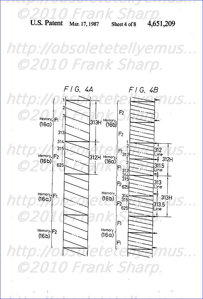 13 lines are not read out because of a time relation. Further, at, for example, the F 2 and F 2 field portions (the portions read out from the memory 16b), the video signal of one line amount is lacked and during that period, the reading operation is stopped and the video signal of one line amount is lacked (shown by one-dot chain lines). The extra and lack of the video signal of one line amount as mentioned above occur in the vertical blanking period so that in practice, this does not disturb the television picture.
 The writing in and reading out from the memories 16a and 16b are controlled by the control circuit 17.
The video signal Sv* derived from the switching circuit 16d is converted to the analog signal by the D/A converter 7 and then fed to the signal processing circuit 8. Then, the red, green and blue primary color signals R, G and B are produced from the signal processing circuit 8 and then fed to the picture receiving tube 9, respectively.
The control circuit 17 produces a vertical synchronizing signal Pv* at the timing shown by arrows in FIG. 4B. More particularly, the vertical synchronizing signal Pv* is produced at the beginning of the first F 1 field, at the timing after 312 lines from the preceding line, namely, at the beginning of the second F 1 field, at the timing after 311.5 lines from the preceding line, at the timing after 313 lines from the preceding line and at the timing after 313.5 lines from the preceding line, or the beginning of the first F 1 field, hereinafter similarly. This synchronizing signal Pv* is supplied through the vertical deflecting circuit 12 to the deflecting coil 13 which then carries out the vertical deflection scanning. When the synchronizing signal Pv* is produced at the above-mentioned timing, in the same F 1 field and F 2 fields, the scanning lines are formed at the same positions and the scanning lines respectively formed at the F 1 field and F 2 field are displaced by 1/2 scanning line spacing each. In other words, the interlaced relation of the video signal Sv is kept as it is.
The video signal Sv* from the D/A converter 7 is supplied to the horizontal synchronizing separating circuit 14. A horizontal synchronizing signal P H * (having the frequency twice the normal frequency) derived from the separating circuit 14 is supplied through the horizontal deflecting circuit 15 to the deflecting coil 13 by which the horizontal deflection scanning is carried out.
Accord
 ing to the example of the television receiver shown in FIG. 3, the horizontal synchronization of the video signal Sv* becomes continuous as shown in FIG. 4B so that the synchronization can be prevented from being disturbed by the insuccessive horizontal synchronization unlike the example of FIG. 1 and thus no picture distortion is produced.
 However, in the example of FIG. 3, since the generation timing of the vertical synchronizing signal Pv* is determined such that the scanning lines of the same F 1 fields and F 2 fields are formed at the same positions (see the arrows in FIG. 4B), the vertical cycle is made different very slightly and not becomes exactly 1/100 second=10 m sec.
By the way, in the television receiver, in order to correct left and right pincushion distortions, a parabolic wave current with the vertical synchronizing frequency is superposed on the horizontal deflection current. In this case, since the cycle of the vertical synchronizing signal Pv* is different (see FIG. 5A) as mentioned above, also the vertical deflection current becomes correspondingly different (see FIG. 5B). Further, the horizontal deflection current waveform is changed at every vertical
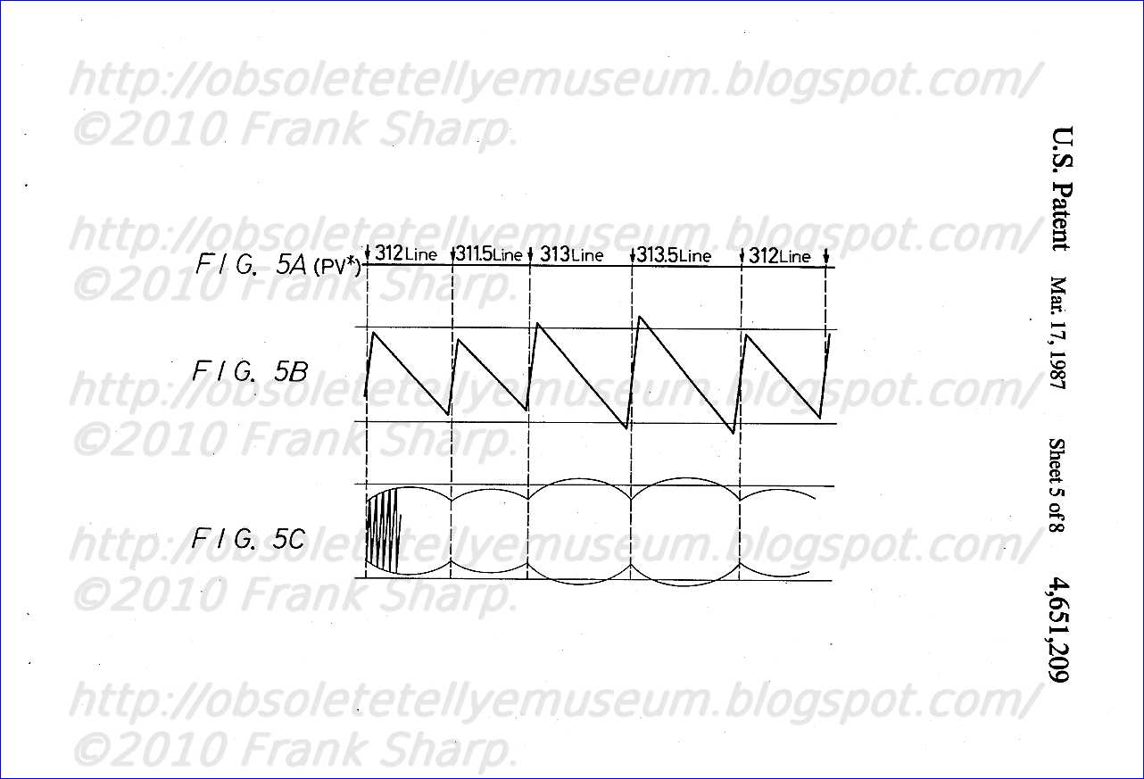 cycle (see FIG. 5C). As described above, since the horizontal deflection current waveform is different, a jitter appears in the right and left ends of the picture screen at a fundamental frequency of 25 Hz (four field cycles of F 1 , F 1 , F 2 , and F 2 ). This jitter becomes conspicuous much if the deflection angle becomes larger.
 To remove this jitter, it may be considered to correct the horizontal deflection current waveform by the deflecting system. However, the correction thereof is very difficult and requires a special deflection correcting circuit.
In this case, since the cycle of the vertical synchronizing signal Pv* becomes different (see FIG. 5A), also the vertical deflecting current becomes different at every vertical cycle (see FIG. 5B) but this does not exert so serious bad influence on the picture screen.
The present invention is to prevent a jitter from being produced at the right and left ends of a picture screen without providing a special deflection correcting circuit. To achieve this object, the present invention is to change the read clock frequency for a field memory which forms a converting circuit for converting the field frequency at the unit of vertical cycle and to make each vertical cycle of a video signal read out from the field memory substantially equal. Thus, the horizontal deflecting current waveforms become equal to each other in each vertical cycle so that a jitter can be prevented from being produced at the right and left ends of the picture screen.
FIGS. 1 and 3 are respectively block diagrams showing prior art examples,
FIGS. 2A, 2B, 4A, 4B, 5A, 5B and 5C are respectively diagrams useful for explaining the prior art examples,
FIG. 6 is a block diagram showing an embodiment of a television receiver according to the present invention,
FIG. 7 is a diagram showing a practical example of a PLL circuit,
FIG. 8 is a block diagram showing another embodiment of the television receiver according to the present invention and
FIG. 9 is a diagram useful for the explanation thereof.
An e
 mbodiment of a television receiver according to the present invention will hereinafter be described with reference to FIG. 6. In FIG. 6, like parts correspocding to those of FIG. 3 are marked with the same references and will not be described in detail.
 In this embodiment, the duration of the period of 312 lines (hereinafter referred to as A field) from the beginning of the first F 1 field, the duration of the period of 311.5 lines (hereinafter referred to as B field) after the preceding period, the duration of the period of 313 lines (hereinafter referred to as C field) after the preceding period and the duration of the period of 313.5 lines (hereinafter referred to as D field) after the preceding period shown in FIG. 4B or the respective vertical cycles become equal to 1/100 sec=10 m sec.
In FIG. 6, reference numeral 19 designates a PLL circuit. This PLL circuit 19 is supplied with the horizontal synchronizing signal P H from the synchronizing separating circuit 18 and produces at its output side a signal with the frequency of, for example, 1250 f H (f H is the horizontal frequency). This signal is supplied through a frequency divider 20 having a frequency dividing ratio of 2 to a write address counter 21 as its write clock pulse. A write address W AD from the counter 21 is supplied through a switching circuit 22 to the memories 16a and 16b. In this case, the PLL circuit 19 is constructed as, for example, shown in FIG. 7. In the figure, reference numeral 23 designates a phase comparator, 24 a low-pass filter, 25 a voltage-controlled type variable frequency oscillator and 26 a 1/N-frequency divider. In this case, N=1250 is established.
In FIG. 6, reference numerals 27, 28, 29 and 30 designate PLL circuits and they produce read clock pulses CL A , CL B , CL C , and CL D of A, B, C and D fields, respectively. These PLL circuits 27 to 30 are supplied with the horizontal synchronizing signal P H from the synchronizing separating circuit 18.
By the way, in this embodiment, since the periods of the A to D fields are made equal to 10 m sec as mentioned above, if the frequencies of the clock pulses CL A , CL B , CL C and CL D produced from the output sides of the PLL circuits 27, 28, 29 and 30 are respectively taken as f A , f B , f C and f D , the following relation is established. ##EQU1## Further, each frequency of these clock pulses CL A to CL D is selected to be substantially twice the frequency of the write clock pulse.
Accordingly, in this embodiment, the frequencies f A , f B , f C and f D of the clock pulses CL A , CL B , CL C and CL D are selected to be 1248 f H , 1246 f H , 1252 f H and 1254 f H , respectively. In this case, also the PLL circuits 27, 28, 29 and 30 are constructed as, for
example, shown in FIG. 7, in which N=1248, 1246, 1252 and 1254 are respectively established. The clock pulses CL A , CL B , CL C and CL D from these PLL circuits 27, 28, 29 and 30 are respectively supplied to a switching circuit 31 and the switching circuit 31 delivers the clock pulses CL A , CL B , CL C and CL D during the periods of the A, B, C and D fields. The clock pulse derived from the switching circuit 31 is supplied to a read address counter 32. A read address R AD from the counter 32 is supplied through the switching circuit 22 to the memories 16a and 16b. In this case, of the memories 16a and 16b, the memory set in the write mode by the switching circuit 22 is supplied with the write address W AD , while the memory set in the read mode thereby is supplied with the read address R AD .
In FIG. 6, reference numeral 33 designates a pincushion distortion correcting circuit, by which a parabolic wave current of vertical synchronizing frequency for use in correcting a pincushion distortion is superposed upon the horizontal deflecting current.
Other circuit elements are formed similarly to those of the example shown in FIG. 3.
This embodiment is constructed as mentioned above, in which during the A, B, C and D fields, the different read clock pulses CL A , CL B , CL C and CL D are supplied respectively and the periods of these A, B, C and D fields, or the respective vertical periods become equal to 10 m sec so that the horizontal deflecting current waveform on which the parabolic wave current of the vertical synchronizing frequency for correcting the right and left pincushion distortions in each vertical period is superposed becomes equal, thus removing such a defect that the jitter is produced at the right and left ends of the picture screen unlike the example of FIG. 3. Accordingly, in this embodiment, it is not necessary to provide the special correcting circuit.
By the way, as described above, since the periods of the A, B, C and D fields become 10 m sec equally, the horizontal cycle of each field becomes different. This difference is, however, very small and can be neglected.
FIG. 8 shows another embodiment of this invention. In FIG. 8, like parts corresponding to those of FIG. 6 are marked with the same references.
In the embodiment shown in FIG. 8, the timing at which the vertical synchronizing signal Pv* is produced is selected to be the timing shown by arrows in FIG. 9. That is, at the timing of the beginning of the first F 1 field, at the timing with a delay of 312 lines after the preceding timing, at the timing with the delay of 312.5 lines after the preceding timing, at the timing with a delay of 313 lines after the preceding timing and at the timing with a delay of 312.5 lines after the preceding timing, or at the timing of the beginning of the first F 1 field and at the similar timing the vertical synchronizing signal Pv* is produced hereinafter.
When the vertical synchronizing signal Pv* is produced at such timings, the scanning line of the F 2 field is displaced upward by one scanning line as compared with the example of FIG. 6. This problem, however, can be solved by delaying the signal supplied to the picture receiving tube 9 by one line amount during the F 2 field or shifting the whole of the signal by one scanning line to the underside during the F 2 field.
In th
 e embodiment of FIG. 8, the duration of the period of 312 lines (hereinafter referred to as A' field) from the beginning of the first F 1 field, the duration of the period of 312.5 lines (hereinafter referred to as B' field) after the preceding period, the duration of the period of 313 lines (hereinafter referred to as C' field) and the duration of the period of 312.5 lines (hereinafter referred to as D' field) after the preceding period, or the respective vertical cycles become 1/100 sec=10 m sec equally.
 In FIG. 8, reference numerals 34, 35 and 36 respectively designate PLL circuits which produce read clock pulses CL B ' (D) ', CL A ' and CL D ' for the periods B'(D'), A' and C'. These PLL circuits 34 to 36 are supplied with the horizontal synchronizing signal P H from the synchronizing separating circuit 18.
In the embodiment of FIG. 8, since the periods of A' to D' fields become 10 m sec equally, if the frequencies of the clock pulses CL B ' (D) ', CL A ' and CL C ' produced from the output sides of the PLL circuits 34, 35 and 36 are respectively taken as f B ' (D) ', f A ' and f C ', the following relation can be established. ##EQU2## Accordingly, in this embodiment of FIG. 8, the frequencies f B ' (D) ', f A ' and f C ' of the clock pulses CL B ' (D) ', CL A ' and CL C ' are respectively selected to be 1250 f H , 1248 f H and 1252 f H .
The clock pulses CL B ' (D) ', CL A ' and CL C ' from these PLL circuits 34, 35 and 36 are respectively supplied to a switching circuit 37 and the switching circuit 37 delivers clock pulses CL B ' (D) ', and CL A ' and CL C ' during the field periods of B'(D'), A' and C'. The clock pulses derived from the switching circuit 37 are supplied to the read address counter 32.
In FIG. 8, the clock pulse CL B ' (D) ' derived from the PLL circuit 34 is supplied through the frequency divider 20 to the write address counter 21 as the write clock pulse therefor.
Other circuit elements are formed similarly to those of the example shown in FIG. 6.
The embodiment of FIG. 8 is constructed as described above. Accordingly, during the respective B'(D'), A' and C' fields, the different read clock pulses CL B ' (D) ', CL A ' and CL C ' are supplied respectively so that the pe
riods of respective A', B', C' and D' fields, or the respective vertical periods become 10 m sec equally. Therefore, the horizontal deflecting current waveforms in the respective vertical periods become equal so that it becomes possible to achieve the similar action and effect to those of the example of FIG. 6. The frequencies of the write clock pulse and the read clock pulse are not limited to those of the above-described embodiments but may be, for example, twice the above frequencies. While in the above-mentioned embodiments the interlaced scanning system of the video system of 625 lines/50 fields and 2:2 is explained, the present invention is not limited to the above system but can be applied similarly to other interlaced scanning system of the other video signal. While in the above-described embodiments the field frequency is selected to be twice, the present invention is not limited to the above field frequency but can be similarly applied to a case in which the field frequency is changed to be three times, four times, . . .
According to the present invention as mentioned above, since the respective vertical cycles are made substantially equal, the horizontal deflecting current waveform on which the parabolic wave current of, for example, the vertical cycle is superposed becomes equal during each vertical period so that the jitter is not produced at the right and left ends of the picture screen. Accordingly, no such special correcting circuit for removing the jitter is required.
Television receiver having interlaced scanning with doubled field frequency,MAIN DEVELOPMENT CONCEPT AND PRIOR ART OVERVIEW:
SONY CRT 100HZ FIELD FREQUENCY DIGITAL SCAN TECHNOLOGY CHASSIS SCC-D68A-A (CHASSIS FX)
A television receiver in which a video signal of an interlaced system is received and converted in field frequency by using field memories (6a) and (6b) and then fed to a picture receiving tube (9). In this case, the picture receiving tube (9) is subjected to a vertical deflection scanning by a vertical synchronizing signal of a constant period and the video signal in each field of the video signal to be supplied to the picture receiving tube (9) is delayed by a predetermi
ned time by controlling, for example, the read-out timings of the field memories (6a) and (6b) to thereby keep an interlace-ratio constant. Consequently, since the respective vertical cycles are equal to one another, even if the parabolic current wave of the vertical cycle for deflection correcting, for example, is superposed on the horizontal deflecting current, the horizontal deflection current waveform is equal in each vertical period so that the jitter can be prevented from being produced at the right and left ends of the picture screen.1. A television receiver comprising:
scan converter means including field-memory means supplied with an input video signal of an interlaced
 television signal having a first field rate and a predetermined interlace-ratio, said field memory means including a plurality of one-field memories, memory control means supplying writing and reading signals to said field-memory means where a frequency of said reading signal is greater than a frequency of said writing signal for reading out a plurality of fields at a second field rate greater than said first field rate, and an output terminal for deriving an output video signal;
 video display means supplied with said output video signal; and
deflection means including vertical deflection means for vertically deflecting said video display means with a vertical synchronizing signal having a constant period, characterized by timing control means for delaying the reading out of at least two selected ones of said plurality of fields and controlling the timing of said output video signal at a vertical rate such that a picture reproduced on said video display means has an interlace-ratio equal to said predetermined interlace-ratio,.
2. A television receiver according to claim 1, wherein said timing control means is provided in said memory control means and controls the timing of said reading signal. 3. A television receiver according to claim 1, wherein said timing control means is formed as a delay compensation circuit operated at a vertical rate and said delay compensation circuit is inserted between said scan converter means and said video display means. 4. A television receiver according to claim 3, wherein said interlace ratio is 2:1, said second field rate is two times said first field rate, and said delay compensation circuit provides a time delay of one-quarter of a horizontal scanning period. 5. A television receiver according to claim 4, wherein said field memory means comprises first and second one-field memories and said memory control means causes readout of said first one-field memory twice in succession and subsequent read out of said second one-field memory twice in succession. 6.
A television receiver according to claim 5, wherein said vertical rate is selected to insert said delay compensation means to delay the second read out of said first one-field memory and to delay the first read out of said second one-field memory. 7. A television receiver according to claim 3, wherein said interlace ratio is 2:1, said second field rate is two times said first field rate, and said delay compensation circuit provides a time delay of one-half of a horizontal scanning period. 8. A television receiver according to claim 1, wherein said interlace ratio is 2:1 and said second field rate is two times said first field rate. 9. A television receiver according to claim 8, wherein said field memory means comprises first and second one-field memories and said memory control means causes read out of said first one-field memory twice in succession and subsequent read out of said second one-field memory twice in succession. 10. A television receiver according to claim 9, wherein said timing control means delays the second read out of said first one-field memory and delays the first read out of said second one-field memory by a fraction of a horizontal scanning period. 11. A television receiver according to claim 10, wherein said fraction consists of one-quarter of a horizontal scanning period. 12. A television receiver according to claim 10, wherein said fraction consists of one-half of a horizontal scanning period.
Description:
The present invention relates to a television receiver which displays a television picture at, for example, a field frequency twice the normal field frequency.
In the existing television system, a so-called interlaced scanning system is carried out. That is, one picture (frame) is transmitted by two vertical scannings (fields). This interlaced scanning system is considered in order to increase the number of scanning lines as much as possible in a limited frequency band without a flicker being perceived by a viewer.
However, in the CCIR system employed mainly in European countries, the field frequency is 50 Hz. By this frequency, the flicker can not be removed completely and the flicker becomes conspicuous particularly when the brightness of the television picture is high.
Therefore, in the prior art, such a television receiver is proposed that a television picture is displayed at a field frequency twice the normal field frequency. FIG. 1 shows an example thereof.
In the figure, reference numeral 1 designates an antenna, 2 a tuner, 3 a video intermediate frequency amplifier, and 4 a video detecting circuit. The video detecting circuit 4 produces a video signal Sv of the interlaced system of, for example, 625 lines/50 fields and 2:1.
This video signal Sv is converted to a digital signal by an A/D converter 5 and then fed to a converting circuit 6 so as to be converted to a field twice normal speed video signal with the field frequency twice the normal field frequency.
The converting circuit 6 is formed of field memories (random access memories each having a storage capacity sufficient for the picture elements of one field period (1V)) 6a and 6b and switching circuits 6c and 6d. The switching circuit 6c is changed in position to the sides of the memories 6a and 6b at every field period 1V, while the switching circuit 6d is changed in position reversely. The memory selected by the switching circuit 6c is suppli
ed with a write clock pulse having a timing corresponding to the above-described picture elements, while the memory selected by the switching circuit 6d is supplied with a read clock pulse with the frequency twice the frequency of the write clock pulse. The video signal Sv converted to the digital signal by the A/D converter 5 is supplied through the switching circuit 6c to the memories 6a and 6b by one field each at every field period 1V in which it is written. The video signal of one field amount, which is written in the memories 6b and 6a during a field period 1V just before the above-mentioned field period, is read out therefrom continuously twice with a cycle of 1/2V. This video signal is derived through the switching circuit 6d. In other words, the switching circuit 6d delivers a field twice normal speed video signal Sv' with the field frequency.
This video signal Sv' is converted to an analog signal by a D/A converter 7 and then fed to a signal processing circuit 8. Then, from the signal processing circuit 8, red, green and blue primary color signals R, G and B are produced and then supplied to an image receiving tube 9, respectively.
The video signal Sv derived from the video detecting circuit 4 is supplied to a vertical synchronizing separating circuit 10. A vertical synchronizing signal Pv derived from the separating circuit 10 is multiplied twice by a frequency multiplyer 11 to be a signal with the frequency twice the ordinary frequency. This signal is supplied through a vertical deflecting circuit 12 to a deflecting coil 13.
The video signal Sv' derived from the D/A converter 7 is supplied to a horizontal synchronizing separating circuit 14. A horizontal synchronizing signal P H ' (having the frequency twice the normal frequency) derived from the separating circuit 14 is supplied through a horizontal deflecting circuit 15 to the deflecting coil 13.
Since the example of the television receiver shown in FIG. 1 is constructed as described above, the primary color si
gnals R, G and B each of which has the field frequency twice the normal field frequency are supplied to the picture receiving tube 9 and the horizontal and vertical deflection scannings are carried out at the scanning speed twice the normal scanning speed, and hence a color picture with the field frequency twice the normal field frequency is displayed on the picture receiving tube 9. Accordingly, also in the above CCIR system, the field frequency becomes 100 Hz which is twice the normal field frequency so that the viewer feels no flicker. In the case of the example shown in FIG. 1, however, the horizontal synchronization of the video signal Sv' derived from the converting circuit 6 is disturbed cyclically so that a distortion occurs in the upper portion of the picture screen.
That is, the write-in state of the video signal Sv derived from the video detecting circuit 4 in the memories 6a and 6b is expressed as shown in FIG. 2A, in which references F 1 and F 2 designate first and second
 fields, respectively. The video signal Sv' from the converting circuit 6 is expressed as shown in FIG. 2B. In the figure, arrows represent the positions of the vertical synchronizing signals. As will be clear from FIG. 2B, in the video signal Sv', the phase of the horizontal synchronization is displaced by 180° at every two fields, or at every 1/50 seconds (shown by broken line arrows), whereby the synchronization on the upper portion of the picture screen is disturbed, resulting in a picture distortion.
 Therefore, the present applicant has proposed a television receiver which is free of such picture distortion and FIG. 3 shows an example thereof. In FIG. 3, like parts corresponding to those of FIG. 1 are marked with the same references.
In the figure, the video signal Sv derived from the video detecting circuit 4 is converted to the digital signal by the A/D converter 5 and then fed to a converting circuit 16 so as to be converted to the field twice normal speed video signal with the frequency twice the normal field frequency.
The converting circuit 16 is formed of field memories (random access memories) 16a and 16b having storage capacities of picture elements of 313 horizontal periods (313H) and 312 horizontal periods (312H) and switching circuits 16c and 16d . The switching circuit 16 is changed in position alternately to the side of the memory 16a during each period of 313H and to the side of the memory 16b during each period of 312H, while the switching circuit 16d is changed in position in the reverse manner. These change-overs of the change-over switches 16c and 16d are controlled by a control circuit 17. This control circuit 17 is supplied with horizontal and vertical synchronizing signals P H and P V which are separated from the video signal Sv by a synchronizing separating circuit 18.
The memory selected by the switching circuit 16c is supplied with the write clock pulse having the timing corresponding to the above picture elements, while the memory selected by the switching circuit 16d is supplied with a read clock pulse with the frequency twice the frequency of the write clock pulse.
The video signal Sv converted to the digital signal by the A/D converter 5 is supplied through the switching circuit 16c to the memories 16a and 16b in which it is alternately written during each period of 313H and 312H. FIG. 4A shows the write-in state of the memories 16a and 16b, in which references F 1 and F 2 represent the first and second fields, respectively. During the periods of 313H and 312H in which the video signal is being written in one of the memories, the video signal w
 ritten in the other of the memories 16b and 16a during the periods just before the above 312H and 313H are read out therefrom twice continuously. This signal is derived through the switching circuit 16d as a field twice normal speed video signal Sv*. FIG. 4B shows the video signal Sv* which is derived through the switching circuit 16d, in which the field portions corresponding to those of FIG. 4A are marked with the same references. By the way, due to the difference between the write time and the read time, extra or lack of one line amount per field is produced in the video signal Sv*.
 In FIG. 4B, at the portions of, for example, the F 1 and F 1 fields (the portions read out from the memory 16a), 313 lines are not read out because of a time relation. Further, at, for example, the F 2 and F 2 field portions (the portions read out from the momory 16b), the video signal of one line amount is lacked and during that period, the reading operation is stopped and the video signal of one line amount is missing (shown by one-dot chain lines). The extra and lack of the video signal of one line amount as mentioned above occur in the vertical blanking period so that in practice, this does not disturb the television picture.
The writing in and reading out from the memories 16a and 16b are controlled by the control circuit 17.
The video signal Sv* derived from the switching circuit 16d is converted to the analog signal by the D/A converter 7 and then fed to the signal processing circuit 8. Then, the red, green and blue primary color signals R, G and
B are produced from the signal processing circuit 8 and then fed to the picture receiving tube 9, respectively. The control circuit 17 produces a vertical synchronizing signal Pv* at the timing shown by arrows in FIG. 4B. More particularly, the vertical synchronizing signal Pv* is produced at the beginning of the first F 1 field, at the timing after 312 lines from the preceding line, namely, at the beginning of the second F 1 field, at the timing after 311.5 lines from the preceding line, at the timing after 313 lines from the preceding line and at the timing after 313.5 lines from the preceding line, or the beginning of the first F 1 field, hereinafter similarly. This synchronizing signal Pv* is supplied through the vertical deflecting circuit 12 to the deflecting coil 13 by which the vertical deflection scanning is carried out. When the synchronizing signal Pv* is produced at the above-mentioned timing, in the same F 1 field and F 2 field , the scanning lines are formed at the same positions and the scanning lines respectively formed at the F 1 field and F 2 field are displaced by 1/2 scanning line spacing each. In other words, the interlaced relation of the video signal Sv is kept as it is.
The video signal Sv* from the D/A converter 7 is supplied to the horizontal synchronizing separating circuit 14. A horizontal synchronizing signal P H * (having the frequency twice the normal frequency) derived from the separating circuit 14 is supplied through the horizontal deflecting circuit 15 to the deflecting coil 13 by which the horizontal deflection scanning is carried out.
According to th
 e example of the television receiver shown in FIG. 3, the horizontal synchronization of the video signal Sv* becomes continuous as shown in FIG. 4B so that the synchronization can be prevented from being disturbed by the insuccessive horizontal synchronization unlike the example of FIG. 1 and thus no picture distortion is produced.
 However, in the example of FIG. 3, since the generation timing of the vertical synchronizing signal Pv* is determined such that the scanning lines of the same F 1 fields and F 2 fields are formed at the same positions (see the arrows in FIG. 4B), the vertical cycle is made different very slightly and not becomes exactly 1/100 seconds=10 m sec.
By the way, in the television receiver, in order to correct left and right pincushion distortions, a parabolic wave current with the vertical synchronizing frequency is superposed on the horizontal deflection current. In this case, since the cycle of the vertical synchronizing signal Pv* is different (see FIG. 5A) as mentioned above, also the vertical deflection current becomes correspondingly different (see FIG. 5B). Further, the horizontal deflection current waveform is changed at every vertical cycle (see FIG. 5C). As described above, since the horizontal deflection current waveform is different, a jitter appears in the right and left ends of the picture screen at a fundamental frequency of 25 Hz (four field cycles of F 1 , F 1 , F 2 , and F 2 ). This jitter becomes conspicuous much if the deflection angle becomes larger.
To r
 emove this jitter, it may be considered to correct the horizontal deflection current waveform by the deflecting system. However, the correction thereof is very difficult and requires a special deflection correcting circuit.
 In this case, since the cycle of the vertical synchronizing signal Pv* becomes different (see FIG. 5A), also the vertical deflecting current becomes different at every vertical cycle (see FIG. 5B) but this does not exert so serious bad influence on the picture screen.
The present invention is to prevent a jitter from being produced at the right and left ends of a picture screen without providing a special deflection correcting circuit. To achieve this object, this invention is to provide a television receiver in which a video signal of the interlaced system is received, its field frequency is converted by using a field memory and then the video signal is fed to a picture receiving tube. In this case, in the picture receiving tube the vertical deflection scanning is performed by the vertical synchronizing signal of a constant cycle and a video signal in each field of the video signal supplied to the picture receiving tube is delayed by a predetermined time so as to keep the interlace-ratio constant.
The television re
ceiver of the present invention is constructed as described above and since each vertical period is equal to one another, the horizontal deflecting current waveforms become equal to one another in each vertical cycle. As a result, the jitter can be prevented from being produced at the right and left ends of the picture screen. FIGS. 1 and 3 are respectively diagrams showing prior art examples, FIGS. 2A, 2B, 4A, 4B, 5A, 5B are respectively diagrams useful for explaining the prior art examples, FIG. 6 is a diagram showing an embodiment of a television receiver according to the present invention, FIGS. 7A, 7B and 8A-8F are respectively diagrams useful for the explanation thereof, FIGS. 9, 10, 12, 13, and 14 are respectively diagrams showing other embodiments of the television receiver according to the present invention, and FIGS. 11A and 11B are diagrams useful for explaining the embodiments of FIGS. 9 and 10.
An embodiment of the television receiver according to the present invention will hereinafter be describe
 d with reference to FIG. 6 In FIG. 6, like parts corresponding to those of FIG. 1 are marked with the same references and the description thereof will be omitted.
 In the embodiment of FIG. 6, the change-over of the switching circuits 6c and 6d and the writing-in operation to the memories 6a and 6b are carried out similarly to those of the example shown in FIG. 1 but by virtue of the control of a memory control circuit 19, the reading out timing from the memories 6a and 6b are controlled so that from the switching circuit 6d derived is a field twice normal speed video signal S VN ' shown in FIG. 7B. That is, one-dot chain lines in FIG. 7B indicate signal-missing portions. In this case, of the first and second F 1 fields read out from the memory 6a, the second F 1 field is read out with a delay of 0.25 H (corresponding to 0.5 line), while of the first and second F 2 fields read out from the memory 6b, the first F 2 field is read out with a delay of 0.25 H (corresponding to 0.5 line).
This
 video signal S VN ' is supplied through the D/A converter 7 to the signal processing circuit 8.
 Further, the video signal S VN ' derived from the D/A converter 7 is supplied to the horizontal synchronizing circuit 14. A horizontal synchronizing signal P HN ' (having the frequency twice the ordinary frequency) therefrom is supplied through the horizontal synchronizing circuit 15 to the deflecting coil 13.
FIG. 7A shows a write-in state of the memories 6a and 6b, in which arrows indicate the positions of the vertical synchronizing signal PV from the vertical synchronizing separating circuit 10.
Further, arrows in FIG. 7B show the positions of signals which are supplied from the multiplier 11 to the vertical deflecting circuit 12. It is natural that the cycles thereof are equal to one another.
In FIG. 6, reference numeral 20 designates a deflection correcting circuit which corrects, for example, the pincushion distortion and this circuit permits a parabolic wave current of the vertical synchronizing frequency for correcting the pincushion distortion to be superposed upon the horizontal deflection current.
Ot
 her circuit elements are arranged similarly to those of the example shown in FIG. 1.
 FIG. 8D shows the scanning line arrangement and the field arrangement in the embodiment of FIG. 6. In FIGS. 8A-8F, black circles and white circles respectively indicate scanning lines. In the embodiment of FIG. 6, since the second F 1 ; field is read out with a delay of 0.25 H, the scanning line in the second F 2 field is formed at the lower side of the scanning line in the first F 1 field with a displacement of 1/2 scanning line interval. Further, since the reading of the first F 2 field is carried out with a delay of 0.25 H, the scanning line in the first F 2 field is formed at the lower side of the scanning line in the second F 2 field with a displacement of 1/2 scanning line interval.
Whereas, FIG. 8A shows the scanning line arrangement and the field arrangement formed by the video signal S V . FIG. 8B shows the like arrangement made by the example of FIG. 1 or 3. Further, FIG. 8C shows the scanning line arrangement and the field arrangement provided for the line multiple speed system in which the two scanning lines by the same signal are continued each. As will be clear from these figures, the synthesis of the first and second F 1 fields of the example of FIG. 6 is equivalent to the F 1 field of the line multiple speed system and the synthesis of the first and second F 2 fields in the example of FIG. 6 becomes equivalent to the F 2 field of this multiple speed system. In other words, the example of FIG. 6 is equivalent to the case where the scanning order of the signal of the previously proposed line multiple speed system is changed such that the signal of 625 lines/50 fields of the non-interlaced system is converted to the signal of the interlaced system with the 312.5 lines/100 fields and 2:1.
According to the television receiver of the embodiment of FIG. 6, since the cycles of the signal to be supplied to the vertical deflecting circuit 12 are equal, the respective vertical periods become equal to one another. Thus, the horizontal deflecting current waveforms on which the parabolic wave current of the vertical synchronizing frequency for correcting the left and right pincushion distortions are superposed are equal to one another during each vertical period. Thus unlike the example of FIG. 3, there occurs no disadvantage that the jitter is produced at the left and right ends of the picture screen and so on. Further, since the interlace-ratio is kept constant, it is possible to obtain a good picture image. Furthermore, according to the embodiment of FIG. 6, since the reading of the second F 1 field is carried out with a delay of 0.25 H and the reading of the first F 2 field is carried out with a delay of 0.25 H, similarly to the example of FIG. 3, the continuity of the horizontal synchronization can be kept and no particular problem is caused.
FIG. 9 is a diagram
 showing another embodiment of the television receiver according to the present invention. In this figure, like parts corresponding to those of FIGS. 1 and 6 are marked with the same references and will not be described in detail.
 In the embodiment of FIG. 9, the read timing from the memories 6a and 6b are not controlled but a delay line is used.
In the embodiment of FIG. 9, the change over of the switching circuits 6c and 6d and the writing in and/or reading out from the memories 6a and 6b are carried out similarly to the example of FIG. 1 so that from the switching circuit 6d, there is derived a field twice normal speed video signal S V ' as shown in FIG. 2B.
In this embo
 diment of FIG. 9, the video signal S V ' converted to the analog signal by the D/A converter 7 is supplied to one fixed contact 21a of a switching circuit 21 and also through a delay line 22 having a delay time of 0.25H (corresponding to 0.5 line) to the other fixed contact 21b thereof. This switching circuit 21 is changed in position to the side of the contact 21a during the first F 1 field and the second F 2 field, while it is changed in position to the side of the contact 21b during the second F 1 ; field and the first F 2 field of the video signal S V '. Accordingly, from this switching circuit 21, there is derived the video signal S VN ' (shown in FIG. 7B) similar to the embodiment of FIG. 6, which then is fed to the signal processing circuit 8.
 The video signal S VN ' from the switching circuit 21 is supplied to the horizontal synchronizing separating circuit 14.
The other elements are arranged similarly to those of the examples of FIGS. 1 and 6.
As a result, also in accordance with the embodiment of FIG. 9, the display similar to that of the embodiment of FIG. 6 can be made and thus similar action and effect can be achieved.
Next, FIG. 10 is a diagram showing other embodiment of the television receiver according to the present invention, in which like parts corresponding to those of FIG. 3 are marked with the same references and will not be de
scribed in detail. In the embodiment of FIG. 10, the change over of the switching circuits 16c and 16d and the write-in operation in the memories 16a and 16b are carried out similarly to those of the embodiment of FIG. 3 but the read timing from the memories 16a and 16b is controlled by the control circuit 17 so that from the switching circuit 16d derived is a field twice the normal speed video signal S VN * shown in FIG. llB. That is, a one-dot chain line in FIG. llB indicates a signal lacked portion and the first and second F 2 fields are read out from the memory 16b with a delay of 0.5 H (corresponding to one line).
This video signal S VN * is supplied through the D/A converter 7 to the signal processing circuit 8.
Further, the video signal S VN * derived from the D/A converter 7 is supplied to the horizontal synchronizing separating circuit 14. A horizontal synchronizing signal P HN * (having the frequency twice the normal frequency) therefrom is supplied through the horizontal deflecting circuit 15 to the deflecting coil 13.
FIG. llA shows the write-in state of the memories 16a and 16b , in which the arrows indicate the positions of the vertical synchronizing signal P V from the synchronizing separating circuit 18.
In the embodiment of FIG. 10, from the control circuit 17, the vertical synchronizing signal P VN * which is produced at the timing shown by the arrows of FIG. llB is supplied to the vertical deflectin
 g circuit 12. That is, the vertical synchronizing signal P VN * is produced at the timing of the beginning of the first F 2 field, at the timing with a delay of 312.5 lines after the preceding timing, at the timing with a delay of 312.5 lines after the preceding timing, at the timing with a delay of 312.5 lines after the preceding timing, and at the timing with a delay of 312.5 lines after the preceding timing, or at the timing of the beginning of the first F 2 field and at the similar timing hereinafter. In this way, the respective cycles of the vertical synchronizing signal P VN * in the embodiment of FIG. 10 are equal to one another.
 In FIG. 10, reference numeral 20 designates a deflection correcting circuit which is used to correct, for example, the pincushion distortion and this deflection correcting circuit is the same as that used in the embodiment of FIG. 6.
The other circuit elements are formed similar to those of the embodiment of FIG. 3.
FIG. 8E s
 hows the scanning line arrangement and the field arrangement in the embodiment of FIG. 10. In the example of FIG. 11, the timing at which the vertical synchronizing signal P VN * is produced is exactly the same as mentioned above and the reading of the first and second F 2 fields is carried out with a delay of 0.5 H so that the scanning line in the first F 1 field and the scanning line in the first F 2 field are formed at the same position, the scanning line in the second F 1 field is formed at the upper side of the scanning line in the first F 1 field with a displacement of 1/2 scanning line interval, and the scanning line in the second F 2 field is formed at the lower side of the scanning line of the first F 2 field by the displacement of 1/2 scanning line interval.
 The synthesis of the first and second F 1 fields of the embodiment of FIG. 10 is equivalent to the F 1 field of the line multiple speed system (see FIG. 8C), while the synthesis of the first and second F 2 fields of the embodiment shown in FIG. 10 becomes equivalent to the F 2 field of the line multiple speed system.
As described above, according to the embodiment of FIG. 10, since the cycles of the vertical synchro
 nizing signal P VN * supplied to the vertical deflecting circuit 12 are equal to one another, the respective vertical periods become equal to one another and thus there occurs no such disadvantage that the jitter will be produced by the fluctuation of each vertical period. Further, since the interlace-ratio is kept constant, it is possible to obtain the picture of good quality. According to this embodiment, since the reading of the first and second F 2 fields is carried out with a delay of 0.5 H, the continuity of the horizontal synchronization can be maintained similarly to the example of FIG. 3 and thus no trouble occurs.
 FIG. 12 shows another embodiment of the television receiver according to the present invention, in which like parts corresponding to those of FIGS. 3 and 10 are marked with the same references and will not be described in detail.
In the embodiment of FIG. 12, instead of controlling the reading out timing from the memories 16a a
 nd 16b, there is used a delay line.
 In the embodiment of FIG. 12, the change over of the switching circuits 16c and 16d and the write-in and/or read-out from the memories 16a and 16b are carried out similarly to those of the example of FIG. 3 and from the switching circuit 16d , there is derived a field twice the normal speed video signal Sv* such as shown in FIG. 4B.
Further, in the embodiment of FIG. 12, the video signal Sv* converted to the analog signal by the D/A converter 7 is supplied to one fixed contact 23a of a switching circuit 23 and also through a delay line 24 having a delay amount of 0.5 H (corresponding to one line) to the other fixed contact 23b thereof. This switching circuit 23 is changed in position to the side of the contact 23a during the first and second F 1 fields of the video signal Sv*, while it is changed in position to the side of the contact 23b during the first and second F 2 fields of the video signal Sv*. Accordingly, from this change-over switch 23, there is derived a video signal S VN * (shown in FIG. llB) similar to that of the embodiment of FIG. 10 and this video signal is fed to the signal processing circuit 8.
Further, the video signal S VN * derived from the switching circuit 23 is supplied to the horizontal synchroniz
ing separating circuit 14. The other circuit elements are arranged similar to those of the examples of FIGS. 3 and 10.
As a result, also in this embodiment of FIG. 12, the display similar to that of the embodiment of FIG. 10 is made and similar action and effect can be achieved.
In the embodiments of FIGS. 10 and 12, while the vertical deflecting circuit 12 is supplied with the vertical synchronizing signal P VN * from the control circuit 17, it is possible that instead of the synchronizing signal P VN * , the vertical synchronizing signal Pv, which is supplied from the synchronizing separating circuit 18, is multiplied by two and then supplied to the vertical deflecting circuit.
FIG. 13 shows another embodiment of the television receiver according to the present invention, in which like parts corresponding to those of FIG. 6 are marked with the same references.
In the embodiment of FIG. 6, the display equivalent to the interlaced system of 312.5 lines/100 fields and 2:1 is carried out so that the flicker on the picture screen can be suppressed and the respective vertical cycles become equal to each other, thus requiring no special deflection correcting circuit. However, if such a construction is employed in which the arrangement of the scanning line as shown in FIG. 8D is used or two scanning lines are continuously formed by the same signal, there occurs a problem that a distortion of step-shape, i.e., a so-called "zig-zag" becomes conspicuous on the inclined portion. This "zig-zag" is described in greater detail in the Japanese patent application (patent application Ser. No. 23998/1983) which was filed by the present applicant.
 The embodiment of FIG. 13 is the example for reducing this "zig-zag".
 In the figure, the video signal S VN ' analog signal by the D/A converter 7 is supplied to an adder 26 which forms a predicting circuit 25. This video signal S VN ' is further supplied through a delay line 27 having a delay amount of 0.5 H (corresponding to one line) to one fixed contact 28a of a switching circuit 28 and the adder 26. Then, in this adder 26, the video signal S VN ' and the signal, which results from delaying this video signal by 0.5 H, are added to each other and then averaged. This added and averaged signal is supplied to the other fixed contact 28b of the switching circuit 28. This switching circuit 28 is changed in position to the side of contact 28a during the first F 1 field and the second F 2 field of the video signal S VN '. (shown in FIG. 7B), while it is changed in position to the side of the contact 28b during the second F 1 field and the first F 2 field of the video signal S VN '. That is, from the switching circuit 28, there are derived a signal, which results from delaying the video signal S VN ' by 0.5 H, in the first F 1 field and the second F 2 field of the video signal S VN ' and a signal, which results from adding and averaging the video signal S VN ' and the signal thereof delayed by 0.5 H, in the second F 1 field and the first F 2 field of the video signal S VN ', respectively.
The signal derived from the switching circuit 28 is supplied to the signal processing circuit 8.
Further, in FIG. 13, a delay line 29 having a delay amount of 0.5 H is connected between the multiplier 11 and the vertical deflecting circuit 12.
The other elements thereof are arranged similar to those of the embodiment shown in FIG. 6.
The scanning line arrangement and the field arrangement in the embodiment of FIG. 13 become as shown in FIG. 8F. As will be clear from this figure, in the embodiment of FIG. 13, the two scanning lines by the same signal are not formed continuously but the interpolation signal is formed by adding and averaging the preceding and following scanning lines so that the above-described so-called "zig-zag" can be alleviated.
 FIG. 14 shows another embodiment of the present invention which is a color television receiver. In this case, after the luminance signal Y and the chrominance signal C are separated from each other, there is used the predicting circuit 25 as shown in the embodiment of FIG. 13.
 In the figure, the video signal S VN ' from the converting ing circuit 6 is supplied to a luminance signal/chrominance signal separating circuit 30. The luminance signal Y from this separating circuit 30 is supplied through the predicting circuit 25 and a D/A converter 7Y to a matrix circuit 31. The chrominance signal C from the separating circuit 30 is supplied to a color demodulating circuit 32 and this color demodulating circuit 32 produces, for example, a red color difference signal R-Y and a blue color difference signal B-Y which then are respectively supplied through D/A converters 7R and 7B to the matrix circuit 31. Then, from the matrix circuit 31, there are produced red, green and blue primary color signals R, G and B which are respectively fed to a picture receiving tube (not shown in FIG. 14).
The output from the D/A converter 7Y is supplied to the horizontal synchronizing separating circuit 14.
The other portions are formed similarly to those of the embodiment of FIG. 6.
In this case, although the predicting circuit 25 may be provided in the chrominance signal system, if it is omitted, the color television receiver of this embodiment becomes inexpensive.
As the embodiment in which the predicting circuit 25 is provided, the embodiments of FIGS. 13 and 14 each of which corresponds to the embodiment of FIG. 6 are illustrated. However, it is possible to similarly consider the embodiments which correspond to the embodiments of FIGS. 9, 10 and 12.
While i
n the above-described embodiments the video signal of the interlaced system having 625 lines/50 fields and 2:1 was described, the present invention is not limited to the above interlaced system video signal but can be similarly applied to the video signal of other interlaced system. Further, while in the above-embodiments, the field frequency is selected to be twice, the present invention is not limited to the above field frequency but can be similarly applied to a case in which the field frequency is converted to be three times, four times, . . . According to the present invention as mentioned above, since the respective vertical cycles are made equal to one another, the horizontal deflecting current waveform on which, for example, the parabolic wave current of the vert
ical cycle is superposed becomes equal during each vertical period so that the jitters at the right and left ends of the picture screen are not produced. Accordingly, no such special correcting circuit for removing the jitter is required. Furthermore, according to the present invention, since the interlace-ratio is kept constant, it is possible to obtain a good picture. CIRCUITS DESCRIPTIONS:
TDA8443A I2C-bus controlled YUV/RGB switch
GENERAL DESCRIPTIONThe TDA8443A is a general purpose two-channel switch
for YUV or RGB signals. One channel provides matrixing
from RGB to YUV, which can be bypassed.
The IC is controlled via I2C-bus by seven different
addresses or can be used in a non-I2C-bus mode. In the
non-I2C-bus mode, control of the circuit is achieved by DC
voltages.
FEATURES
· Two RGB/YUV selectable clamped inputs with
associated synchronization
· RGB/YUV matrix
· 3-state switching with an OFF-state
· Selectable gain
· I2C-bus or non-I2C-bus mode
· Address selection for 7 devices
· Fast switching.
FUNCTIONAL DESCRIPTION
The circuit contains two sets of inputs (see Fig.1). Both
channels can receive RGB or YUV signals. Each set of
inputs has its own synchronization input, which internally
generates a pulse to clamp the inputs. The internal
clamping pulse can also be controlled by a signal (e.g. a
sandcastle pulse) applied to pin 24. The pulse will occur
during the time that the signal at pin 24 is between
5.5 and 6.5 V. If both a sync signal and a pin 24 signal are
used the signal should be applied to pin 24 via a 1 kW
resistor.
RGB signals of Channel 2 can be matrixed to YUV signals.
The outputs can be set in a high impedance OFF state,
which allows the use of seven devices in parallel
(I2C-bus mode).
The circuit can be controlled by an I2C-bus compatible
microcontroller or directly by DC voltages. The fast
switching input can be operated via pin 16 of the
peritelevision connector.
Input clamps
The R, G, B respectively (R-Y), Y and (B-Y) video signals
are AC-coupled to the IC where they are clamped on the
black level. The timing information for this clamping action
is derived from the associated synchronization signal
SYNC, which could also consist of the composite video
information signal CVBS. The syncsignal is AC-coupled to
the IC where it is clamped on top-sync level, information
obtained from this action is used to generate the clamp
pulses.
The clamp pulses can be generated in two ways:
1. Using the sync information (internal clamping)
The sync information is clamped on top-sync and the
information obtained from this action is used to switch
an internal current source at pin 24.
Pin 24 shou
ld be connected to VP via a 4.7 kW resistor,and a 1 nF capacitor to ground. During video scan the
voltage at pin 24 will be HIGH (equals positive supply
voltage). During the synchronization pulses the
voltage at pin 24 will drop to zero because of the
current sink (2.5 mA).
When the synchronization pulse is over, the current
source is switched off and the voltage at pin 24 will rise
to its higher level. Because of the time constant at
pin 24, the restoration will take some microseconds.
The voltage at pin 24 is also sensed internally and at
the time it is between 0.456VP and 0.544VP, a time
pulse is generated and used for the clamping action.
2. Using a sandcastle pulse (external clamping)
If an associated sandcastle pulse is available, it can
also be used as a clamping pulse. In this event the
sandcastle pulse should be connected to pin 24, the
top of the clamping pulse should be between 0.544VP
and 0.456VP. The timing of the internal clamping pulse
will be equal to the timing of the higher part of the
sandcastle pulse. If the sync signal is also connected,
the current sink will also become active during the
synchronization pulses. This means that the
sandcastle pulse should be connected to pin 24 via a
1 kW dropping resistor. In this event only the
sandcastle pulse at pin 24 will be influenced during
sync pulses, but the sandcastle pulse at the
sandcastle source will be unchanged.
TDA2595 Horizontal combination
GENERAL DESCRIPTION
The TDA2595 is a monolithic integrated circuit intended for use in colour television receivers.
Features
· Positive video input; capacitively coupled (source impedance < 200 W)· Adaptive sync separator; slicing level at 50% of sync amplitude
· Internal vertical pulse separator with double slope integrator
· Output stage for vertical sync pulse or composite sync depending on the load; both are switched off at muting
· j1 phase control between horizontal sync and oscillator
· Coincidence detector j3 for automatic time-constant switching; overruled by the VCR switch
· Time-constant switch between two external time-constants or loop-gain; both controlled by the coincidence detector j3
· j1 gating pulse controlled by coincidence detector j3
· Mute circuit depending on TV transmitter identification
· j2 phase control between line flyback and oscillator; the slicing levels for j2 control and horizontal blanking can be set
separately
· Burst keying and horizontal blanking pulse generation, in combination with clamping of the vertical blanking pulse
(three-level sandcastle)
· Horizontal drive output with constant duty cycle inhibited by the protection circuit or the supply voltage sensor
· Detector for too low supply voltage
· Protection circuit for switching off the horizontal drive output continuously if the input voltage is below 4 V or higher
than 8 V
· Line flyback control causing the horizontal blanking level at the sandcastle output continuously in case of a missing
flyback pulse
· Spot-suppressor controlled by the line flyback control.
TDA4555 Multistandard decoder
GENERAL DESCRIPTION
The TDA4555 and TDA4556 are monolithic integrated
multist
andard colour decoders for the PAL, SECAM,NTSC 3,58 MHz and NTSC 4,43 MHz standards. The
difference between the TDA4555 and TDA4556 is the
polarity of the colour difference output signals (B-Y)
and (R-Y).
Features
Chrominance part
· Gain controlled chrominance amplifier for PAL, SECAM
and NTSC
· ACC rectifier circuits (PAL/NTSC, SECAM)
· Burst blanking (PAL) in front of 64 ms glass delay line
· Chrominance output stage for driving the 64 ms glass
delay line (PAL, SECAM)
· Limiter stages for direct and delayed SECAM signal
· SECAM permutator
Demodulator part
· Flyback blanking incorporated in the two synchronous
demodulators (PAL, NTSC)
· PAL switch
· Internal PAL matrix
· Two quadrature demodulators with external reference
tuned circuits (SECAM)
· Internal filtering of residual carrier
· De-emphasis (SECAM)
· Insertion of reference voltages as achromatic value
(SECAM) in the (B-Y) and (R-Y) colour difference output
stages (blanking)
Identification part
· Automatic standard recognition by sequential inquiry
· Delay for colour-on and scanning-on
· Reliable SECAM identification by PAL priority circuit
· Forced switch-on of a standard
· Four switching voltages for chrominance filters, traps
and crystals
· Two identification circuits for PAL/SECAM (H/2) and
NTSC
· PAL/SECAM flip-flop
· SECAM identification mode switch (horizontal, vertical
or combined horizontal and vertical)
· Crystal oscillator with divider stages and PLL circuitry
(PAL, NTSC) for double colour subcarrier frequency
· HUE control (NTSC)
· Service switch.
TEA2031A COLOR TV EAST-WEST CORRECTION
DESCRIPTION
The TEA2031A is intended to ensure frame rate
modulated parabolic and keystone corrections to
the horizontal deflection circuitry of 110° color TV
sets.
The linear frame saw-tooth is applied to appropriate
circuitry from which a corresponding parabolic
waveforms is obtained. This waveform is then fed
to a comparator together with the linear line sawtooth
for comparison. Comparator’s output drives
the output power stage which is capable of sinking
the external coil currents of up to 0.5A.
An internal recovery diode feeds back to the power
supply the coil fly-back current pulses of as high as
0.5A.
GENERAL DESCRIPTION
The TEA2031A is intended to provide to 110° color
TV sets a parabolic and keystone frame rate modulated
correction in addition to the main horizontal
scanning.
A stable 6.3V internal reference provides current
and voltage references to the whole IC.
Pins 1 and 2 are two symmetrical inputs of an onchip
multiplier circuit and are internally held at
6.3V reference potential level. Current inputs to
these pins are drawn from external sources via appropriate
resistors. The frame saw-tooth waveform
which has a peak-to-peak value of around 3
volts and a mean value of about 2.5 volts, supplies the required current via a series resistor to pin 1.
Likewise, the current to pin 2 is drawn through a
series resistor from an external dc voltage source.
These series resistors can have values of around
40kΩ resulting in input currents of approximately
0.1mA ± modulation current.
Pin 7 should be loaded to ground through a 100kΩ
resistor which as a result will produce a parabola
of 5 volts peak-to-peak at pin 7. This parabola is
symmetrical if the DC current flowing into pin 2 is
equal to the mean input current of pin 1. Otherwise,
the parabola becomes dissymmetrical and
produces a keystone effect correction.
The line saw-tooth at pin 8 is obtained by feeding
the line fly-back voltage through an integrator network
formed by a diode and a grounded capacitor
(see typical application diagram). The DC component
of the line saw-tooth is compensated by an internal
current sinking source ; so that the mean DC
values of line saw-tooth and frame parabola voltages
are equal.
Line saw-tooth and frame parabola signals are applied
to a comparator whose output is in the form
of width modulated pulses. During every pulse duration,
the output (pin 5) can sink external coil currents
of up to 0.5A associated with diode
modulator of the main horizontal scanning circuit.
An internal recovery diode feeds back the fly-back
energy of the coil to the power supply. This diode
can carry currents of up to 0.5A.
TV Stereo Decoder with Matrix TDA6600-2
SIEMENSPreliminary Data Bipolar IC
The TDA 6600-2 includes an advanced decoder for the identification signals for the
multic
hannel TV sound systems according to the dual-carrier system as well as a matrixswitched by the decoder to provide the L-Ft-information.
Features
0 Increased switching reliability and recognition by means of two PLLs for stereo
(117 Hz) and / or dual channel (274 Hz)
0 Separate bandwidth selection for dual-tone (pins 17-18) and stereo (pins 14-15)
0 Separate setting for the PLL time constants for dual-tone (pin 10) and stereo (pin 11)
0 Adjustable cut level for dual-tone (pin 8) and stereo (pin 9)
0 Cross-talk rejection independent of external component accuracy
0 Adjustment to minimal cross-talk level through external DC voltage
0 Suitable for TV sets with a 15625-Hz signal.
Type Ordering Code Package
TDA 6600-2 Q67000-A8210 P-DlP-24
Circuit Description
The circuitry has two functional sections:
Two phase locked loops for generating the required comparison frequencies (54.96
kHz and 54.8 kHz) from the line frequency. The phase detectors of the control loops
operate in a frequency range of 117 Hz and/or 274 Hz.
Four demodulators to evaluate the 54-kHz pilot signal. The capacitors at the mixer
outputs determine the bandwidth (and thus the signal-to-noise ratio) of the pilot tone
recognition.
An evaluation circuitry for decoding "stereo", "dual sound", and "mono" from the mixer
output levels. ln order to assure interference-free operation in case of high noise level
input signals, the individual signals "stereo" and "dual sound" are delayed via an
externally adjustable integrator. The subsequent digital evaluation provides the
information "mono", "dual sound", or "stereo" to the matrix and the 4 level input/output
(to drive the TDA 6200). If this four level input/output is connected to ground externally
(e.g. by the TDA 6200), the decoder will recognize this signal as "forced mono".
A stereo matrix with deemphasis and SCART output switched by the pilot frequency
decoder. The SCART output can be disabled by a MUTE signal (coincidence).
UPC1377C NEC Electronics
Power supply voltage for vertical part:
15V current drain for horizontal part: 30 synchronization signal processor of color TV.
For horizontal deflection circuit and vertical deflection circuit of color TV set.
SONY KV-FX29TA CHASSIS SCC-B98 A-A (FX CHASSIS) Television receiver which can indicate the numeral of a channel SONY On Screen Display TECHNOLOGY.
A television receiver having a CPU (central processing unit), a ROM (read only memory) in which a program and a font data are written, and a RAM (random access memory) for work area and a shift register. The font
data to be indicated as a channel numeral is loaded to the shift register by an interrupt procedure and the output from the shift register is supplied to the video signal system whereby to indicate the channel numeral after the channel is changed. 1. A television receiver for receiving a video signal that includes a synchronizing signal, said receiver comprising:
a central processing unit having an interrupt function;
bus means connected to said central processing unit;
read only memory means connected to said central processing unit through said bus means and containing a control program to be executed by said central processing unit;
random access memory means connected to said central processing unit through said bus means and used as a work area of said central processing unit;
channel selecting means connected to said central processing unit through said bus means for selecting one of a plurality of channels;
control signal receiving circuit means connected to said central processing unit through said bus means for receiving a control signal and controlling said channel selecting means;
shift register means connected to said central processing unit through said bus means;
clock pulse generating means for supplying a clock pulse to said shift register means synchronized with the synchronizing signal of said video signal and generating a serial signal representing a character pattern from said shift register means; and
mixing means for mixing said video signal and said serial signal;
said control program in said read only memory means containing font data to be displayed, a main program for decoding said control signal and controlling said channel selecting means, and an interrupt program for loading the font data from said read only memory means into said shift register means.
2. A television receiver according to claim 1; further comprising an integrated circuit chip, said central processing unit, said bus means, said read only memory means, said random access memory means and said shift register means being formed on said chip. 3. A television receiver according to claim 1; wherein said synchronizing signal includes a horizontal synchronizing pulse, said central processing unit is interrupted by said horizontal synchronizing pulse, and said interrupt program is started by said horizontal synchronizing pulse. 4. A television receiver according to claim 3; wherein a horizontal trace period follows said synchronizing signal and said font data from said read only memory means is loaded into said shift register means during a first portion of the horizontal trace period and said serial signal is generated dur
ing a second portion of the horizontal trace period.
Description:
BACKGROUND OF THE INVENTION
1. Field of the Invention
The present invention relates generally to a television receiver and more particularly is directed to a television receiver which can indicate the numeral of a channel after the channel is changed.
2. Description of the Prior Art
There is proposed a television receiver in which when a channel is changed, the numeral indicative of the channel after the channel is changed is indicated on the screen of a cathode ray tube during a predetermined period. Such previously proposed television receiver is disclosed in U.S. Pat. No. 3,748,645, U.S. Pat. No. 3,812,285 and so on. A conventional channel indicator used in such television receiver requires a special LSI (large scale integration) chip to indicate the numeral of the channel. However, such LSI chip requires a substantial investment in time and money from its designing to the completion, and when the designing thereof is changed midway, it is quite difficult to cope with such change.
Moreover, it is difficult to give an individuality to the character pattern of the numeral indicating the channel. Furthermore, the number of ICs (integrated circuits) is increased and hence the manufacturing cost is inevitably raised.
OBJECTS AND SUMMARY OF THE INVENTION
Accordingly, it is an object of the present invention to provide an improved television receiver which is free from the problem inherent to the prior art.
It is another object of the present invention to provide a television receiver which can indicate the numeral of a channel after the channel is changed by employing a microcomputer.
It is still another object of the present invention to provide a television receiver in which an individuality can easily be given to the character pattern of the numeral of a channel to be indicated.
It is further object of the present invention to provide a television receiver which can reduce the number of integrated circuits.
According to one aspect of the present invention, there is provided a television receiver comprising:
(a) a central processing unit having an interrupt function;
(b) a bus means connected to said central processing unit;
(c) a read only memory means connected to said central processing unit through said bus means and containing a control program to be executed by said central processing unit;
(d) a random access memory means connected to said central processing unit through said bus means and used as a work area of said central processing unit;
(e) a channel selecting means connected to said central processing unit through said bus means for selecting one of a plurality of channels and producing a video signal; and
 (f) a control signal receiving circuit means connected to said central processing unit through said bus means for receiving a control signal and controlling said channel selecting means;
characterized in that said television receiver comprises:
(g) a shift register means connected to said central processing unit through said bus means;
(h) a clock pulse generating means for supplying a clock pulse to said shift register means synchronized with the synchronizing signal of said video signal and generating a serial signal representing a character pattern from said shift register;
(i) a mixing means for mixing said video signal and said serial signal; and
(j) an interrupt means for interrupting an operation of said central processing unit synchronized with a synchronizing pulse of the video signal, said control program in said read only memory means containing a font data to be displayed, a main program for decoding said control signal and controlling said channel selecting means, and an interrupt program for loading the font data from said read only memory means to said shift register means.
The other objects, features and advantages of the present invention will become apparent from the following description taken in conjunction with the accompanying drawings through which the like references designate the same elements and parts.
BRIEF DESCRIPTION OF THE DRAWINGS
FIG. 1 is a schematic block diagram of an embodiment of a television receiver according to the present invention;
FIG. 2 is a table showing a 16-bit font data used in the present invention;
FIG. 3 is a diagram showing a screen of the television receiver of the present invention on which a numeral of channel is indicated and waveforms of pulses used in explanation thereof;
FIG. 4 is a diagram showing the format of a remote control signal used in the present invention; and
FIGS. 5 to 8 are respectively flow charts used to explain the operation of the present invention.
DESCRIPTION OF THE PREFERRED EMBODIMENT
Now, an embodiment of a television receiver according to the present invention will hereinafter be described with reference to the attached drawings.
In FIG. 1 showing an example of the present invention, reference numeral 10 generally designates a video signal system, 11 a tuner, 12 a video intermediate frequency (VIF) amplifier, 13 a video detecting c ircuit, 14 a video amplifier and 15 a cathode ray tube, respectively. In this case, the tuner 11 is formed as an electronic tuning system which can receive the video signal of a desired channel by changing a value of a tuning voltage Ec supplied thereto.
Reference numeral 20 generally designates a microcomputer, 21 a 4-bit parallel CPU (central processing unit), 22 a ROM (read only memory) in which a program and a font data for indicating a numeral of a channel are written or stored, 23 a RAM (random access memory) for a work area and 31 to 36 input/output ports. These circuits 22 to 36 are connected through a bus 24 to the CPU 21.
Reference numeral 37 designates a 16-bit serial/parallel input and serial output shift register. This shift register 37 is used to generate a signal Sn which indicates the numeral of the channel. To the shift register 37 loaded line by line in parallel is a 16-bit font data indicating the numeral of a channel as, for example, shown in FIG. 2 from the port 32. The font data loaded to the shift register 37 is delievered therefrom in series from MSB (most significant bit) as the signal Sn. At that time, the serial input terminal of the shift register 37 is made at "0" level.
The signal Sn derived from the shift register 37 is supplied to the video amplifier 14 in which the signal Sn is composed on or mixed with the video signal.
The microcomputer 20 together with this shift register 37 is formed as one chip IC (integrated circuit).
Reference numeral 41 designates a D/A (digital-to-analog) converter. The output from the port 31 is supplied to this D/A converter 41 from which the tuning voltage Ec is derived. This tuning voltage Ec is supplied to the tuner 11.
Reference numeral 42 designates a receiving element which receives a remote control signal and 43 its receiving circuit connected thereto. When the remote control signal is, for example, an infrared remote control signal, the receiving element 42 is formed as an infrared ray receiving element and the receiving circuit 43 generates a remote control signal Sr. This remote control signal Sr is the signal which corresponds to an output from a remote control signal transmitter (not shown) and has a format as, for example, shown in FIG. 4. Namely, in this remote control signal, a guide pulse having a pulse width of 2400 μsec exists in the beginning and code pulses of 16 bits from b 0 to b 15 follow the guide pulse with an interval of 600 μsec. In this case the code pulses b 0 to b 15 indicate "0" or "1" in respose to the content of the remote control. When "0", the pulse width is selected as 600 μsec, while when "1", the pulse width is selected as 1200 μsec. This remote control signal Sr is supplied to the port 33.
Reference numeral 44 designates a non-volatile memory which is connected to the port 34 and in which a digital value of the tuning voltage Ec at each channel is stored. Reference numeral 45 designates an input key which is used to change the channel, the sound volume and so on, in which the dynamic scan is carried out by the output from the port 35, and the switching output from which is inputted to the port 36 to detect which key is operated.
Reference numeral 51 designates a synchronizing (sync) separating circuit to which the video signal from the video detector circuit 13 is supplied and from which a vertical synchronizing pulse Pv and a horizontal synchronizing pulse Ph are derived respectively. These pulses Pv and Ph are supplied to the CPU 21 as interrputing signals H-INT and V-INT. The pulse Ph is supplied to a monostable multivibrator 52 which generates a pulse P 52 which becomes "1" from a falling down or trailing edge time point t 1 of the pulse Ph to a start time point t 2 of the display period of the numeral of the channel as shown in FIG. 3 (in which reference numeral 151 designates the screen of the cat hode ray tube). This pulse P 52 is supplied to a gated oscillating circuit 53 as its oscillating control signal so that from the gated oscillating circuit 53 is derived an oscillating pulse P 53 during the period from t 2 to t 4 in which the pulse P 52 is "0" as shown in FIG. 3. This pulse P 53 is supplied to the shift register 37 as the clock. At that time, the frequency of the pulse P 53 is selected as a value corresponding to a dot pitch in the lateral direction of the numeral of the channel to be indicated.
Accordingly, since the font data on, for example, the first line in FIG. 2 is loaded to the shift register 37 during the first half period from t 1 to t 2 of the 45th horizontal trace period, this font data is extracted from the shift register 37 as the serial signal Sn in response to the pulse P 53 during the second half period from t 2 to t 3 of the above horizontal trace period and then supplied to the video amplifier 14, the numeral of the channel on the first line is indicated on the screen 151 in the interval corresponding to the period from t 2 to t 3 of the 45th line. Although during the period from t 3 to t 4 the pulse P 53 is supplied to the shift register 37, the serial input terminal of the shift register 37 is at "0" level and this "0" level is derived from the shift register 37 during the period from t 3 to t 4 so that no numeral of the channel is indicated on the screen 151 in the interval corresponding to the period from t 3 to t 4 .
When such operation is performed for the 45th to 51st horizontal lines by employing the font data on the 1st to 7th lines shown in FIG. 2, the channel numeral corresponding to the font data in FIG. 2 is displayed as shown in FIG. 3. If the data of all "0" is loaded to the shift register 37 as the font data, the channel numeral is not indicated.
FIGS. 5 to 8 respectively show flow charts of the programs written in the ROM 22 and FIG. 5 shows the main routine thereof.
This main routine shown in FIG. 5 s tarts from a step 501 and in a step 502 the initializing is carried out. Thus, a flag FLG, a buffer BUFF and counters CHCNT, HCNT and WCNT are set in, for example, the RAM 23 and these are all reset (cleared) to "0".
A step 503 is such a step in which the existence or not of the remote control signal Sr is judged by the existence or not of the guide pulse, namely, by detecting whether the "1" level of the signal Sr lasts 2400 μsec or not. A step 504 is such a step which judges whether or not there is the input to the key 45, and a step 531 is such a step which judges whether the counter CHCNT is "0" or not. Consequently, when powered, CHCNT=0 is established in the step 502 so that the loop of step 503➝step 504➝step 531➝step 503 is repeated to thereby poll the input of the remote control signal Sr and the input from the key 45. In this case, the counter CHCNT serves as a flag indicative of the existence or not of the request for changing the channel and a timer for setting the displaying period of the channel numeral.
When the remote control signal Sr exists, the bits b 0 to b 15 of the signal Sr are latched in a step 800 and the step is moved to a step 511. Also when an input exists in the step 504, the step 504 moves to the step 511, too. In the step 511, it is judged whether the remote control input in the step 800 and the key input in the step 504 are the commands for changing the channel or not.
When the above inputs are the command for changing the channel, the counter CHCNT is set to "1" in a next step 512. Subsequently, in a step 513, on the basis of the channel data indicated by the remote control signal Sr inputted at the step 800 and the key input in the step 504, a digital tuning voltage data E D for tuning to the channel is read out from the non-volatile memory 44 (see FIG. 1). This digital tuning voltage data E D is outputted to the port 31 in a step 514. Thus, by the analog tuning voltage Ec from the D/A converter 41, the television receiver is set in the receiving state of the channel inputted in the step 800 or 504, thereafter.
In a step 515, from the ROM 22, a font data (data as, for example, shown in FIG. 2) displayed as a numeral of a new channel after the channel is changed is loaded to the buffer BUFF. Although the detail will be described later, the font data in the buffer BUFF is sequentially loaded line by line to the shift register 37 during the 45th to 51st horizontal trace period t 1 to t 2 of each field in accordance with a subroutine 700 shown in FIG. 7. As a result, the channel numeral after the channel is changed is indicated on the screen 151.
When the channel numeral is indicated on the screen 151, the procedure step is returned to the step 503. At that time, since CHCNT=1 is established in the step 512, the procedure step is moved in the order of the step 503➝the step 504➝the step 531➝a step 532. In this step 532, the counter CHCNT is incremented by "1" and in a next step 533, whether the count CHCNT reaches a predetermined value MAX or not is checked where the value MAX is the value corresponding to the period during which the channel numeral is displayed upon changing the channel.
And, if CHCNT
When CHCNT=MAX is esbalished, the buffer BUFF is cleared to "0" in a step 541. Therefore, since "0" is loaded through the buffer BUFF to the shift register 37 as the font data, Sn="0" is established thereafter so that the channel numeral is not indicated any more.
In a next step 542, the counter CHCNT is reset to "0" and the procedure step is returned to the step 503.
As described above, when the channel change data is inputted, the channel is changed and the channel numeral after the channel is changed is indicated during a constant period.
When the inputs in the steps 800 and 504 are not the commands for changing the channel but the commands for changing, for example, the sound volume, in a step 521 the counter CHCNT is reset to "0" and then in a step 522, the operation based on the commands inputted in the steps 800 and 504 is carried out. The circuitry for executing the procedure except for changing the channel can be made the same as in the prior art and hence it is omitted to show the same in FIG. 1.
On the other hand, FIGS. 6 and 7 respectively show subroutines in which the font data in the buffer BUFF is loaded to the shift register 37. The subroutine 600 shown in FIG. 6 is the interrupt subroutine which is exe cuted when the interrupt procedure is executed by the vertical synchronizing pulse Pv. When the vertical synchronizing pulse Pv is supplied to the CPU 21, this subroutine 600 starts from a step 601 and in a step 602, the counter HCNT is reset to "0". In a step 603, the subroutine 600 is ended and returned to the original main routine.
Accordingly, by this subroutine 600, the counter HCNT is reset to "0" at every start point of each field.
The subroutine 700 shows in FIG. 7 is the interrupt subroutine which is executed when the interrupt procedure is executed by the horizontal synchronizing pulse Ph. When the horizontal synchronizing pulse Ph is supplied to the CPU 21, the subroutine 700 starts from a step 701 and in a step 702, a flag FLG indicative of whether the subroutine 700 is executed or not is set to "1". Then, in a step 703, the counter HCNT is incremented by "1". In this case, since the counter HCNT is reset to "0" by the subroutine 600 at every start point of each field and the subroutine 700 is executed at each horizontal syncronizing pulse Ph, the counter HCNT indicates the line number of the horizontal line at each field period.
In a next step 704, the magnitude of the counter HCNT is checked. When 45≤HCNT≤51, in a step 711, the font data in the buffer BUFF (the data as, for example, shown in FIG. 2) is loaded line by line to the shift register 37 from the buffer BUFF each time when the counter HCNT is incremented by "1" each (at every horizontal lines). On the other hand, when 45≤HCNT≤51 is not established, in a step 721, all "0" is loaded to the shift register 37. Then, the subroutine 700 is ended at a next step 712 and returned to the original main routine.
If necessary, the subroutine 700 is provided with a timer routine by which the duration of time necessary for completing the subroutine 700 is set as 40 μsec (the period shorter than the period from t 1 to t 2 ).
Consequently, during the period from t 1 to t 2 in the 45th to 51st horizontal trace periods, by the subroutine 700 the data in the buffer BUFF is loaded to the shift register 37. Then, if the data loaded to the shift register 37 is the font data, the channel numeral is indicated during the period from t 2 to t 3 . While during the period from t 1 to t 2 in other horizontal trace period, the data indicative of all "0" is loaded to the shift register 37 from the buffer BUFF so that the channel numeral during the period t 2 to t 3 is not displayed.
Upon changing the channel, during the predetermined period, the font data regarding the channel numeral after the channel is changed is loaded to the buffer BUFF in the step 515. After that, since the data indicative of all "0" is loaded to the buffer BUFF in the step 541, in accordance with the subroutine 700, during the predetermined period from the change of the channle, the channel numeral after the channel is changed is indicated on the screen 151 as shown in FIG. 3. After the predetermined period elapses, the display is not carried out any more.
FIG. 8 shows a su broutine 800 which is used to read the remote control signal Sr. This subroutine 800 starts from a step 801. In a next step 802, a pointer i is reset to "0" and in a succeeding step 811, a delay corresponding to the "0" level period of 600 μsec between the trailing edge of the guide pulse and the rising edge of the bit b 0 (see FIG. 4) is carried out. Further, in a next step 821, the counter WCNT is reset to "0". In this case, the pointer i indicates a particular bit of the bits b 0 to b 15 of the remote control signal Sr and i=0 to 15. Also, the counter WCNT is used to check the respective pulse widths of the bits b 0 to b 15 .
After the delay of 70 μsec is performed in a succeeding step 822, whether the flag FLG is "0" or "1" is checked in a next step 823. When FLG=0, namely, the interrupt procedure is not executed, the counter WCNT is incremented by "1" in a following step 824. When FLG=1, namely, the interrupt procedure is executed, the counter WCNT is incremented by "2" in a step 825 and the processing time due to the interrupt procedure is corrected. Thereafter, the flag FLG is reset to "0" in a next step 826. Then, in a step 827, it is checked whether the level of ith bit of the remote control signal Sr reaches the "0" level or not, namely, whether ith bit is ended or not. When ith bit is not ended, the step 827 returns to the step 822, while when ended, the step 827 advances to a step 831.
Accordingly, during the period in which the level of ith bit of the signal Sr is at the "1" level, the loop from the steps 822 to 827 is repeated. Upon repeating the loop from the steps 822 to 827, if the interrupt subroutine 700 is not executed at all, the FLG=0. Therefore, in the steps 822 and 824, the counter WCNT is incremented by "1" each at every 40 μsec. Thus, at the time when the above loop is ended, if ith bit is "0" (namely, the pulse width is 600 μsec), WCNT=15, while if ith bit is "1" (namely, the pulse width is 1200 μsec), WCNT=30 (the processing time necessary for other steps is neglected for simplicity).
Upon repeating this loop from the steps 822 to 827, if the interrupt subroutine 700 is executed, 40 μsec is consumed to execute such subroutine. This is the same as that necessary for executing the step 822 once. Also, at that time, since FLG=1 (step 702), the counter WCNT is incremented by "2" in the step 825. As a result, at the time when this loop is ended, if ith bit is "0", WCNT=15, while if ith bit is "1", WCNT=30.
After the above loop is ended, the counter WCNT is checked in the step 831. If WCNT≤15, the level "0" of ith bit is set in the RAM 23 in a step 832, while if WCNT>15, the level "1" of ith bit is set in the RAM 23 in a step 833. In a next step 834, whether the above procedure is executed for all the bits of the remote control signal Sror not is checked by the pointer i. When the above procedure is not yet executed for all the bits, the pointer i is incremented by "1" in a step 835 and then the step 835 returns to the step 811. On the contrary, when the above procedure is executed for all the bits, the step 834 advances to a step 841.
In the step 841, the remote control signal Sr is judged on the basis of the data in the steps 832 and 833. And, in a step 842, this subroutine 800 is ended and returned to the original main routine.
As set forth above, according to the present invention, it is possible to perform the change of the channel and to indicate the channel numeral at that time. In this case, particularly in accordance with the present invention, the change of the channel and the indication of the channel numeral after the channel is changed are carried out by the use of the ordinary microcomputer 20 so that the time and cost necessary from designing to completing can be reduced extremely. Moreover, when the designing is changed in the midway thereof, the designing can be changed with ease.
Further, the individuality can be given to the character pattern of the numeral of the channel to be indicated with ease. Also, since the number of the ICs can be reduced, this is advantageous for reducing the manufacturing cost and for increasing reliablity.
In addition, in the above description, it is possible to provide the steps 531 to 542 in the subroutine 600.
The above description is given on a single preferred embodiment of the invention, but it will be apparent that many modifications and variations could be effected by one skilled in the art without departing from the spirits or scope of the novel concepts of the invention, so that the scope of the invention should be determined by the appended claims only.
1. Field of the Invention
The present invention relates generally to a television receiver and more particularly is directed to a television receiver which can indicate the numeral of a channel after the channel is changed.
2. Description of the Prior Art
There is proposed a television receiver in which when a channel is changed, the numeral indicative of the channel after the channel is changed is indicated on the screen of a cathode ray tube during a predetermined period. Such previously proposed television receiver is disclosed in U.S. Pat. No. 3,748,645, U.S. Pat. No. 3,812,285 and so on. A conventional channel indicator used in such television receiver requires a special LSI (large scale integration) chip to indicate the numeral of the channel. However, such LSI chip requires a substantial investment in time and money from its designing to the completion, and when the designing thereof is changed midway, it is quite difficult to cope with such change.
Moreover, it is difficult to give an individuality to the character pattern of the numeral indicating the channel. Furthermore, the number of ICs (integrated circuits) is increased and hence the manufacturing cost is inevitably raised.
OBJECTS AND SUMMARY OF THE INVENTION
Accordingly, it is an object of the present invention to provide an improved television receiver which is free from the problem inherent to the prior art.
It is another object of the present invention to provide a television receiver which can indicate the numeral of a channel after the channel is changed by employing a microcomputer.
It is still another object of the present invention to provide a television receiver in which an individuality can easily be given to the character pattern of the numeral of a channel to be indicated.
It is further object of the present invention to provide a television receiver which can reduce the number of integrated circuits.
According to one aspect of the present invention, there is provided a television receiver comprising:
(a) a central processing unit having an interrupt function;
(b) a bus means connected to said central processing unit;
(c) a read only memory means connected to said central processing unit through said bus means and containing a control program to be executed by said central processing unit;
(d) a random access memory means connected to said central processing unit through said bus means and used as a work area of said central processing unit;
(e) a channel selecting means connected to said central processing unit through said bus means for selecting one of a plurality of channels and producing a video signal; and
(f) a control signal receiving circuit means connected to said central processing unit through said bus means for receiving a control signal and controlling said channel selecting means; characterized in that said television receiver comprises:
(g) a shift register means connected to said central processing unit through said bus means;
(h) a clock pulse generating means for supplying a clock pulse to said shift register means synchronized with the synchronizing signal of said video signal and generating a serial signal representing a character pattern from said shift register;
(i) a mixing means for mixing said video signal and said serial signal; and
(j) an interrupt means for interrupting an operation of said central processing unit synchronized with a synchronizing pulse of the video signal, said control program in said read only memory means containing a font data to be displayed, a main program for decoding said control signal and controlling said channel selecting means, and an interrupt program for loading the font data from said read only memory means to said shift register means.
The other objects, features and advantages of the present invention will become apparent from the following description taken in conjunction with the accompanying drawings through which the like references designate the same elements and parts.
BRIEF DESCRIPTION OF THE DRAWINGS
FIG. 1 is a schematic block diagram of an embodiment of a television receiver according to the present invention;
FIG. 2 is a table showing a 16-bit font data used in the present invention;
FIG. 3 is a diagram showing a screen of the television receiver of the present invention on which a numeral of channel is indicated and waveforms of pulses used in explanation thereof;
FIG. 4 is a diagram showing the format of a remote control signal used in the present invention; and
FIGS. 5 to 8 are respectively flow charts used to explain the operation of the present invention.
DESCRIPTION OF THE PREFERRED EMBODIMENT
Now, an embodiment of a television receiver according to the present invention will hereinafter be described with reference to the attached drawings.
In FIG. 1 showing an example of the present invention, reference numeral 10 generally designates a video signal system, 11 a tuner, 12 a video intermediate frequency (VIF) amplifier, 13 a video detecting c
 ircuit, 14 a video amplifier and 15 a cathode ray tube, respectively. In this case, the tuner 11 is formed as an electronic tuning system which can receive the video signal of a desired channel by changing a value of a tuning voltage Ec supplied thereto.
 Reference numeral 20 generally designates a microcomputer, 21 a 4-bit parallel CPU (central processing unit), 22 a ROM (read only memory) in which a program and a font data for indicating a numeral of a channel are written or stored, 23 a RAM (random access memory) for a work area and 31 to 36 input/output ports. These circuits 22 to 36 are connected through a bus 24 to the CPU 21.
Reference numeral 37 designates a 16-bit serial/parallel input and serial output shift register. This shift register 37 is used to generate a signal Sn which indicates the numeral of the channel. To the shift register 37 loaded line by line in parallel is a 16-bit font data indicating the numeral of a channel as, for example, shown in FIG. 2 from the port 32. The font data loaded to the shift register 37 is delievered therefrom in series from MSB (most significant bit) as the signal Sn. At that time, the serial input terminal of the shift register 37 is made at "0" level.
The signal Sn derived from the shift register 37 is supplied to the video amplifier 14 in which the signal Sn is composed on or mixed with the video signal.
The microcomputer 20 together with this shift register 37 is formed as one chip IC (integrated circuit).
Reference numeral 41 designates a D/A (digital-to-analog) converter. The output from the port 31 is supplied to this D/A converter 41 from which the tuning voltage Ec is derived. This tuning voltage Ec is supplied to the tuner 11.
Reference numeral 42 designates a receiving element which receives a remote control signal and 43 its receiving circuit connected thereto. When the remote control signal is, for example, an infrared remote control signal, the receiving element 42 is formed as an infrared ray receiving element and the receiving circuit 43 generates a remote control signal Sr. This remote control signal Sr is the signal which corresponds to an output from a remote control signal transmitter (not shown) and has a format as, for example, shown in FIG. 4. Namely, in this remote control signal, a guide pulse having a pulse width of 2400 μsec exists in the beginning and code pulses of 16 bits from b 0 to b 15 follow the guide pulse with an interval of 600 μsec. In this case the code pulses b 0 to b 15 indicate "0" or "1" in respose to the content of the remote control. When "0", the pulse width is selected as 600 μsec, while when "1", the pulse width is selected as 1200 μsec. This remote control signal Sr is supplied to the port 33.
Reference numeral 44 designates a non-volatile memory which is connected to the port 34 and in which a digital value of the tuning voltage Ec at each channel is stored. Reference numeral 45 designates an input key which is used to change the channel, the sound volume and so on, in which the dynamic scan is carried out by the output from the port 35, and the switching output from which is inputted to the port 36 to detect which key is operated.
Reference numeral 51 designates a synchronizing (sync) separating circuit to which the video signal from the video detector circuit 13 is supplied and from which a vertical synchronizing pulse Pv and a horizontal synchronizing pulse Ph are derived respectively. These pulses Pv and Ph are supplied to the CPU 21 as interrputing signals H-INT and V-INT. The pulse Ph is supplied to a monostable multivibrator 52 which generates a pulse P 52 which becomes "1" from a falling down or trailing edge time point t 1 of the pulse Ph to a start time point t 2 of the display period of the numeral of the channel as shown in FIG. 3 (in which reference numeral 151 designates the screen of the cat
 hode ray tube). This pulse P 52 is supplied to a gated oscillating circuit 53 as its oscillating control signal so that from the gated oscillating circuit 53 is derived an oscillating pulse P 53 during the period from t 2 to t 4 in which the pulse P 52 is "0" as shown in FIG. 3. This pulse P 53 is supplied to the shift register 37 as the clock. At that time, the frequency of the pulse P 53 is selected as a value corresponding to a dot pitch in the lateral direction of the numeral of the channel to be indicated.
 Accordingly, since the font data on, for example, the first line in FIG. 2 is loaded to the shift register 37 during the first half period from t 1 to t 2 of the 45th horizontal trace period, this font data is extracted from the shift register 37 as the serial signal Sn in response to the pulse P 53 during the second half period from t 2 to t 3 of the above horizontal trace period and then supplied to the video amplifier 14, the numeral of the channel on the first line is indicated on the screen 151 in the interval corresponding to the period from t 2 to t 3 of the 45th line. Although during the period from t 3 to t 4 the pulse P 53 is supplied to the shift register 37, the serial input terminal of the shift register 37 is at "0" level and this "0" level is derived from the shift register 37 during the period from t 3 to t 4 so that no numeral of the channel is indicated on the screen 151 in the interval corresponding to the period from t 3 to t 4 .
When such operation is performed for the 45th to 51st horizontal lines by employing the font data on the 1st to 7th lines shown in FIG. 2, the channel numeral corresponding to the font data in FIG. 2 is displayed as shown in FIG. 3. If the data of all "0" is loaded to the shift register 37 as the font data, the channel numeral is not indicated.
FIGS. 5 to 8 respectively show flow charts of the programs written in the ROM 22 and FIG. 5 shows the main routine thereof.
This main routine shown in FIG. 5 s
 tarts from a step 501 and in a step 502 the initializing is carried out. Thus, a flag FLG, a buffer BUFF and counters CHCNT, HCNT and WCNT are set in, for example, the RAM 23 and these are all reset (cleared) to "0".
 A step 503 is such a step in which the existence or not of the remote control signal Sr is judged by the existence or not of the guide pulse, namely, by detecting whether the "1" level of the signal Sr lasts 2400 μsec or not. A step 504 is such a step which judges whether or not there is the input to the key 45, and a step 531 is such a step which judges whether the counter CHCNT is "0" or not. Consequently, when powered, CHCNT=0 is established in the step 502 so that the loop of step 503➝step 504➝step 531➝step 503 is repeated to thereby poll the input of the remote control signal Sr and the input from the key 45. In this case, the counter CHCNT serves as a flag indicative of the existence or not of the request for changing the channel and a timer for setting the displaying period of the channel numeral.
When the remote control signal Sr exists, the bits b 0 to b 15 of the signal Sr are latched in a step 800 and the step is moved to a step 511. Also when an input exists in the step 504, the step 504 moves to the step 511, too. In the step 511, it is judged whether the remote control input in the step 800 and the key input in the step 504 are the commands for changing the channel or not.
When the above inputs are the command for changing the channel, the counter CHCNT is set to "1" in a next step 512. Subsequently, in a step 513, on the basis of the channel data indicated by the remote control signal Sr inputted at the step 800 and the key input in the step 504, a digital tuning voltage data E D for tuning to the channel is read out from the non-volatile memory 44 (see FIG. 1). This digital tuning voltage data E D is outputted to the port 31 in a step 514. Thus, by the analog tuning voltage Ec from the D/A converter 41, the television receiver is set in the receiving state of the channel inputted in the step 800 or 504, thereafter.
In a step 515, from the ROM 22, a font da
ta (data as, for example, shown in FIG. 2) displayed as a numeral of a new channel after the channel is changed is loaded to the buffer BUFF. Although the detail will be described later, the font data in the buffer BUFF is sequentially loaded line by line to the shift register 37 during the 45th to 51st horizontal trace period t 1 to t 2 of each field in accordance with a subroutine 700 shown in FIG. 7. As a result, the channel numeral after the channel is changed is indicated on the screen 151. When the channel numeral is indicated on the screen 151, the procedure step is returned to the step 503. At that time, since CHCNT=1 is established in the step 512, the procedure step is moved in the order of the step 503➝the step 504➝the step 531➝a step 532. In this step 532, the counter CHCNT is incremented by "1" and in a next step 533, whether the count CHCNT reaches a predetermined value MAX or not is checked where the value MAX is the value corresponding to the period during which the channel numeral is displayed upon changing the channel.
And, if CHCNT
When CHCNT=MAX is esbalished, the buffer BUFF is cleared to "0" in a step 541. Therefore, since "0" is loaded through the buffer BUFF to the shift register 37 as the font data, Sn="0" is established thereafter so that the channel numeral is not indicated any more.
In a next step 542, the counter CHCNT is reset to "0" and the procedure step is returned to the step 503.
As described above, when the channel change data is inputted, the channel is changed and the channel numeral after the channel is changed is indicated during a constant period.
When the inputs in the steps 800 and 504 are not the commands for changing the channel but the commands for changing, for example, the sound volume, in a step 521 the counter CHCNT is reset to "0" and then in a step 522, the operation based on the commands inputted in the steps 800 and 504 is carried out. The circuitry for executing the procedure except for changing the channel can be made the same as in the prior art and hence it is omitted to show the same in FIG. 1.
On the other hand, FIGS. 6 and 7 respectively show subroutines in which the font data in the buffer BUFF is loaded to the shift register 37. The subroutine 600 shown in FIG. 6 is the interrupt subroutine which is exe
 cuted when the interrupt procedure is executed by the vertical synchronizing pulse Pv. When the vertical synchronizing pulse Pv is supplied to the CPU 21, this subroutine 600 starts from a step 601 and in a step 602, the counter HCNT is reset to "0". In a step 603, the subroutine 600 is ended and returned to the original main routine.
 Accordingly, by this subroutine 600, the counter HCNT is reset to "0" at every start point of each field.
The subroutine 700 shows in FIG. 7 is the interrupt subroutine which is executed when the interrupt procedure is executed by the horizontal synchronizing pulse Ph. When the horizontal synchronizing pulse Ph is supplied to the CPU 21, the subroutine 700 starts from a step 701 and in a step 702, a flag FLG indicative of whether the subroutine 700 is executed or not is set to "1". Then, in a step 703, the counter HCNT is incremented by "1". In this case, since the counter HCNT is reset to "0" by the subroutine 600 at every start point of each field and the subroutine 700 is executed at each horizontal syncronizing pulse Ph, the counter HCNT indicates the line number of the horizontal line at each field period.
In a next step 704, the magnitude of the counter HCNT is checked. When 45≤HCNT≤51, in a step 711, the font data in the buffer BUFF (the data as, for example, shown in FIG. 2) is loaded line by line to the shift register 37 from the buffer BUFF each time when the counter HCNT is incremented by "1" each (at every horizontal lines). On the other hand, when 45≤HCNT≤51 is not established, in a step 721, all "0" is loaded to the shift register 37. Then, the subroutine 700 is ended at a next step 712 and returned to the original main routine.
If necessary, the subroutine 700 is provided with a timer routine by which the duration of time necessary for completing the subroutine 700 is set as 40 μsec (the period shorter than the period from t 1 to t 2 ).
Consequently, during the period from t 1 to t 2 in the 45th to 51st horizontal trace periods, by the subroutine 700 the data in the buffer BUFF is loaded to the shift register 37. Then, if the data loaded to the shift register 37 is the font data, the channel numeral is indicated during the period from t 2 to t 3 . While during the period from t 1 to t 2 in other horizontal trace period, the data indicative of all "0" is loaded to the shift register 37 from the buffer BUFF so that the channel numeral during the period t 2 to t 3 is not displayed.
Upon changing the channel, during the predetermined period, the font data regarding the channel numeral after the channel is changed is loaded to the buffer BUFF in the step 515. After that, since the data indicative of all "0" is loaded to the buffer BUFF in the step 541, in accordance with the subroutine 700, during the predetermined period from the change of the channle, the channel numeral after the channel is changed is indicated on the screen 151 as shown in FIG. 3. After the predetermined period elapses, the display is not carried out any more.
FIG. 8 shows a su
 broutine 800 which is used to read the remote control signal Sr. This subroutine 800 starts from a step 801. In a next step 802, a pointer i is reset to "0" and in a succeeding step 811, a delay corresponding to the "0" level period of 600 μsec between the trailing edge of the guide pulse and the rising edge of the bit b 0 (see FIG. 4) is carried out. Further, in a next step 821, the counter WCNT is reset to "0". In this case, the pointer i indicates a particular bit of the bits b 0 to b 15 of the remote control signal Sr and i=0 to 15. Also, the counter WCNT is used to check the respective pulse widths of the bits b 0 to b 15 .
 After the delay of 70 μsec is performed in a succeeding step 822, whether the flag FLG is "0" or "1" is checked in a next step 823. When FLG=0, namely, the interrupt procedure is not executed, the counter WCNT is incremented by "1" in a following step 824. When FLG=1, namely, the interrupt procedure is executed, the counter
WCNT is incremented by "2" in a step 825 and the processing time due to the interrupt procedure is corrected. Thereafter, the flag FLG is reset to "0" in a next step 826. Then, in a step 827, it is checked whether the level of ith bit of the remote control signal Sr reaches the "0" level or not, namely, whether ith bit is ended or not. When ith bit is not ended, the step 827 returns to the step 822, while when ended, the step 827 advances to a step 831. Accordingly, during the period in which the level of ith bit of the signal Sr is at the "1" level, the loop from the steps 822 to 827 is repeated. Upon repeating the loop from the steps 822 to 827, if the interrupt subroutine 700 is not executed at all, the FLG=0. Therefore, in the steps 822 and 824, the counter WCNT is incremented by "1" each at every 40 μsec. Thus, at the time when the above loop is ended, if ith bit is "0" (namely, the pulse width is 600 μsec), WCNT=15, while if ith bit is "1" (namely, the pulse width is 1200 μsec), WCNT=30 (the processing time necessary for other steps is neglected for simplicity).
Upon repeating this loop from the steps 822 to 827, if the interrupt subroutine 700 is executed, 40 μsec is consumed to execute such subroutine. This is the same as that necessary for executing the step 822 once. Also, at that time, since FLG=1 (step 702), the counter WCNT is incremented by "2" in the step 825. As a result, at the time when this loop is ended, if ith bit is "0", WCNT=15, while if ith bit is "1", WCNT=30.
After the above loop is ended, the counter WCNT is checked in the step 831. If WCNT≤15, the level "0" of ith bit is set in the RAM 23 in a step 832, while if WCNT>15, the level "1" of ith bit is set in the RAM 23 in a step 833. In a next step 834, whether the above procedure is executed for all the bits of the remote control signal Sr
or not is checked by the pointer i. When the above procedure is not yet executed for all the bits, the pointer i is incremented by "1" in a step 835 and then the step 835 returns to the step 811. On the contrary, when the above procedure is executed for all the bits, the step 834 advances to a step 841. In the step 841, the remote control signal Sr is judged on the basis of the data in the steps 832 and 833. And, in a step 842, this subroutine 800 is ended and returned to the original main routine.
As set forth above, according to the present invention, it is possible to perform the change of the channel and to indicate the channel numeral at that time. In this case, particularly in accordance with the present invention, the change of the channel and the indication of the channel numeral after the channel is changed are carried out by the use of the ordinary microcomputer 20 so that the time and cost necessary from designing to completing can be reduced extremely. Moreover, when the designing is changed in the midway thereof, the designing can be changed with ease.
Further, the individuality can be given to the character pattern of the numeral of the channel to be indicated with ease. Also, since the number of the ICs can be reduced, this is advantageous for reducing the manufacturing cost and for increasing reliablity.
In addition, in the above description, it is possible to provide the steps 531 to 542 in the subroutine 600.
The above description is given on a single preferred embodiment of the invention, but it will be apparent that many modifications and variations could be effected by one skilled in the art without departing from the spirits or scope of the novel concepts of the invention, so that the scope of the invention should be determined by the appended claims only.
SONY KV-FX29TA CHASSIS SCC-B98 A-A (FX CHASSIS) SONY CHASSIS SCC-B98 A-A DST EHT FBT TRANSFORMER Bobbin structure for high voltage transformers EHT Output.
A coil bo
bbin for a fly-back transformer or the like having a bobbin proper. A plurality of partition members or flanges are formed on the bobbin proper with a slot between adjacent ones. At least first and second coil units are formed in the bobbin proper, each having several slots, formed between the flanges, and first and second high voltage coils are wound on the first and second coil units in opposite directions, respectively. A rectifying means is connected in series to the first and second coil units, and a cut-off portion or recess is provided on each of the partition members. In this case, a wire lead of the coil units passes from one slot to an adjacent slot through the cut-off portion which is formed as a delta groove, and one side of the delta groove is corresponded to the tangent direction to the winding direction. 1. A fly-back transformer comprising a coil bobbin comprising a plurality of parallel spaced discs with a first adjacent plurality of said disc formed with delta shaped slots having first edges which extend tangentially to a first winding direction and a first winding wound on said first adjacent plurality of said discs in said first winding direction, a second adjacent plurality of said discs formed with delta shaped slots having first edges which extend tangentially to a second winding direction opposite said first winding direction and a second winding wound on said second adjacent plurality of said discs in said second winding direction, a third adjacent plurality of said discs formed with delta shaped slots having first edges which extend tangentially to said first winding direction and a third winding wound on said third adjacent plurality of said discs in said first winding direction and said second plurality of adjacent discs mounted between said first and third plurality of adjacent discs. 2. A fly-back transformer according to claim 1 wherein adjacent ones of said first adjacent plurality of discs are mounted such that their delta shaped slots are orientated 180 degrees relative to each other. 3. A fly-back transformer according to claim 2 including a first winding turning partition mounted between said first and second adjacent plurality of discs and formed with grooves and notches for changing winding direction between said first and second windings and a second winding turning partition mounted between said second and third adjacent plurality of discs and formed with grooves and notches for changing the winding direction between said second and third windings. 4. A fly-back transformer according to claim 3 wherein said first and second winding turning partitions are formed with winding guiding slots for guiding the winding between the first, second and third adjacent plurality of discs. 5. A fly-back transformer according to claim 2 including a first rectifying means connected between one end of said first winding and one end of said second winding, and a second rectifying means connected between the second end of said second winding and one end of said third winding. 6. A fly-back transformer according to claim 5 wherein the second end of said first winding is grounded and a third rectifying means connected between the second end of said third winding and an output terminal.
Description:
BACKGROUND OF THE INVENTION
1. Field of the Invention
The present invention relates generally to a bobbin structure for high voltage transformers, and is directed more particularly to a bobbin structure for high voltage transformer suitable for automatically winding coils thereon.
2. Description of the Prior Art
In the art, when a wire lead is reversely wound on a bobbin separately at every winding block, a boss is provided at every winding block and the wire lead is wound on one block, then one end of the wire lead is tied to the boss where it will be cut off. The end of the wire lead is tied to another boss, and then the wire lead is wound in the opposite direction. Therefore, the prior art winding method requires complicated procedures and the winding of the wire lead cannot be rapidly done and also the winding can not be performed automatically. Further, the goods made by the prior art method are rather unsatisfactory and have a low yield.
OBJECTS AND SUMMARY OF THE INVENTION
Accordingly an object of the invention is to provide a coil bobbin for a fly-back transformer or the like by which a wire lead can be automatically wound on winding blocks of the coil bobbin even though the winding direction is diff erent among the different winding blocks.
Another object of the invention is to provide a coil bobbin for a fly-back transformer or the like in which a bridge member and an inverse engaging device for transferring a wire lead from one wiring block to an adjacent wiring block of the coil bobbin and wiring the wire lead in opposite wiring directions between adjacent wiring blocks, and a guide member for positively guiding the wire lead are provided.
According to an aspect of the present invention, a coil bobbin for a fly-back transformer or the like is provided which comprises a plurality of partition members forming a plurality of slots, a first coil unit having several slots on which a first high voltage coil is wound in one winding direction, a second coil unit having several slots on which a second high voltage coil is wound in the other direction, a rectifying means connected in series to the first and second coil units, and a cut-off portion provided on each of the partition members, a wire lead passing from one slot to an adjacent slot through the cut-off portions, each of the cut-off portions being formed as a delta groove, and one side of the delta groove corresponding to a tangent to the winding direction.
The other objects, features and advantages of the present invention will become apparent from the following description taken in conjunction with the accompanying drawings through which the like reference numerals and letters designate the same elements and parts, respectively.
BRIEF DESCRIPTION OF THE DRAWINGS
FIG. 1 is a schematic diagram showing the construction of a fly-back transformer;
FIG. 2 is a connection diagram showing an example of the electrical connection of the fly-back transformer shown in FIG. 1;
FIG. 3 is a schematic diagram showing an example of a device for automatically winding a wire lead of the fly-back transformer on its bobbin;
FIG. 4 is a perspective view showing an example of the coil bobbin according to the present invention;
FIG. 5 is a plan view of FIG. 4;
FIGS. 6 and 7 are views used for explaining recesses or cut-off portions shown in FIGS. 4 and 5; and FIGS. 8A and 8B cross-sectional views showing an example of the inverse engaging means according to the present invention.
DESCRIPTION OF THE PREFERRED EMBODIMENT
When the high voltage winding of a fly-back transformer used in a high voltage generating circuit of a television receiver is divided into plural ones and then wound on a bobbin, the divided windings (divided coils) are connected in serie s through a plurality of rectifying diodes.
When the winding is divided into, for example, three portions, such as divided coils La, Lb and Lc, they are wound on a bobbin proper 1 from, for example, left to right sequentially in this order as shown in FIG. 1. In this case, if the divided coils La and Lc are selected to have the same sense of turn and the middle coil Lb is selected to have the opposite sense of turn from the coils La and Lc, the distance between the terminal end of coil La and the start of coil Lb and the distance between the terminal end of coil Lb and the start of coil Lc can be got relatively long. Therefore, diodes Da and Db can be mounted by utilizing the space above the block on which the middle coil Lb is wound as shown in FIG. 1, so that it becomes useless to provide spaces for diodes between the divided coils La and Lb and between the divided coils Lb and Lc and hence the bobbin proper 1 can be made compact.
FIG. 2 is a connection diagram showing the connection of the above fly-back transformer. In FIG. 2, reference numeral 2 designates a primary winding (Primary coil) of the fly-back transformer, reference letter L designates its high voltage winding (secondary coil), including divided coils La, Lb and Lc, 3 an output terminal, and 4 a lead wire connected to the anode terminal of a cathode ray tube (not shown), respectively.
An example of the bobbin structure according to the invention, which is suitable to automatically wind coils, which are different in sense of turn in each winding block as shown in FIG. 1, on the bobbin, will be hereinafter described with reference to the drawings.
FIG. 3 is a diagram showing an automatic winding apparatus of a wire lead on a coil bobbin. If it is assumed that the wire lead is wound in the order of w inding blocks A, B and C in FIG. 1 and the wire lead is wound on the block A with the bobbin proper 1 being rotated in the counter-clockwise direction as shown in FIG. 3, the relation between the bobbin proper 1 and the wire lead becomes as shown in FIG. 3. In this figure, reference numeral 6 designates a bobbin for feeding the wire lead.
Turning to FIG. 4, an example 10 of the bobbin structure or coil bobbin according to the present invention will be described now. In this example, the winding blocks A, B and C for the divided coils La, Lb and Lc are respectively divided into plural slots or sections by plural partition members or flanges 11, and a cut-off portion or recess 12 is formed on each of the flanges 11 through which the wire lead in one section is transferred to the following winding section.
As shown in FIG. 6, each recess 12 is so formed that its one side extends in the direction substantially coincident with the tangent to the circle of the bobbin proper 1 and its direction is selected in response to the sense of turn of the winding or wire lead. In this case, the direction of recess 12 means the direction of the opening of recess 12, and the direction of recess 12 is selected opposite to the sense of turn of the wi nding in the present invention.
Now, recesses 12A, which are formed in the winding block A, will be now described by way of example. The positions of recesses 12A formed on an even flange 11Ae and an odd flange 11A 0 are different, for example, about 180° as shown in FIGS. 6A and 6B. Since the bobbin proper 1 is rotated in the counter-clockwise direction in the winding block A and hence the sense of turn of the wire lead is in the clockwise direction, the recess 12A is formed on the even flange 11Ae at the position shown in FIG. 6A. That is, the direction of recess 12A is inclined with respect to the rotating direction of bobbin proper 1 as shown in FIG. 6A. In this case, one side 13a of recess 12A is coincident with the tangent to the circle of bobbin proper 1, while the other side 13b of recess 12A is selected to have an oblique angle with respect to the side 13a so that the recess 12A has a predetermined opening angle.
The opening angle of recess 12A is important but the angle between the side 13a of recess 12A and the tangent to the circle of bobbin proper 1 is also important in the invention. When the wire lead is bridged or transferred from one section to the following section through the recess 12A, the wire lead in one section advances to the following section in contact with the side 13a o f recess 12A since the bobbin proper 1 is rotated. In the invention, if the side 13a of recess 12A is selected to be extended in the direction coincident with the tangent to the circle of bobbin proper 1, the wire lead can smoothly advance from one section to the next section without being bent.
In the invention, since the middle divided coil Lb is wound opposite to the divided coil La, a recess 12B provided on each of flanges 11B of the winding block B is formed to have an opening opposite to that of recess 12A formed in the winding block A as shown in FIGS. 6C and 6D.
As shown in FIG. 5, terminal attaching recesses 14 are provided between the winding blocks A and B to which diodes are attached respectively. In the illustrated example of FIG. 5, a flange 15AB is formed between the flanges 11A 0 and 11B 0 of winding blocks A and B, and the recesses 14 are formed between the flanges 11A 0 and 15AB and between 15AB and 11B 0 at predetermined positions. Then, terminal plates 16, shown in FIG. 4, are inserted into the recesses 14 and then fixed there to, respectively. The terminal plates 16 are not shown in FIG. 5. Between the winding blocks B and C and between the blocks A and B, similar terminal attaching recesses 14 are formed, and terminal plates 16 are also inserted thereinto and then fixed thereto.
As described above, since the divided coil Lb is wound opposite to the divided coils La and Lc, it is necessary that the winding direction of the wire lead be changed when the wire lead goes from the block A to block B and also from the block B to block C, respectively.
Turning to FIG. 7, an example of the winding or wire lead guide means according to the present invention will be now described. In FIG. 7, there are mainly shown a bridge member for the wire lead and an inve rse member or means for the wire lead which are provided between the winding blocks A and B. At first, a bridge means 20 and its guide means 21, which form the bridge member, will be described. The bridge means 20 is provided by forming a cut-out portion or recess in the middle flange 15AB located between the winding blocks A and B. In close relation to the bridge means or recess 20, the guide means 21 is provided on a bridge section X A at the side of block A. This guide means 21 is formed as a guide piece which connects an edge portion 20a of recess 20 at the winding direction side to the flange 11A 0 of block A in the oblique direction along the winding direction through the section X A .
Next, an inverse engaging means 22 will be now described with reference to FIGS. 7 and 8. If the flange 11B 0 of FIG. 7 is viewed from the right side, the inverse engaging means 22 can be shown in FIG. 8A. In this case, the tip end of one side 13a of recess 12B 1 is formed as a projection which is extended outwards somewhat beyond the outer diameter of flange 11B 0 . The inverse engaging means 22 may take any configuration but it is necessary that when the rotating direction of the bobbin proper 1 is changed to the clockwise direction, the wire lead can be engaged with the recess 12B 1 or projection of one side 13a and then suitably transferred to the next station.
Another guide means 23 is provided on a bridge section X B at the side of winding block B in close relation to the inverse engaging means 22. The guide means 23 is formed as a guide surface which is a projected surface from the bottom surface of section X B and extended obliquely in the winding direction. This guide means or guide surface 23 is inclinded low into the means 22 and has an edge 23a which is continuously formed between the middle flange 15AB and the flange 11B 0 .
In this case, it is possible that the guide means 21 and guide surface 23 are formed to be the same in construction. That is, both the guide means 21 and 23 can be made of either the guide piece, which crosses the winding section or guide surface projected upwards from the bottom surface of the winding section. It is sufficient if the guide means 21 and 23 are formed to smoothly transfer the wire lead from one section to the next section under the bobbin proper 1 being rotated.
Although not shown, in connection with the middle flange 15BC between the winding blocks B and C, there are provided similar bridge means 20, guide means 21, inverse engaging means 22 and another guide means 23, respectively. In this case, since the winding direction of the wire lead is reversed, the forming directions of the means are reverse but their construction is substantially the same as that of the former means. Therefore, their detailed description will be omitted.
According to the bobbin structure of the invention with the construction set forth above, the wire lead, which is transferred from the block A to the section X A by the rotation of bobbin proper 1, is wound on the section X B from the section X A after being guided by the guide piece 21 to the recess 20 provided on the middle flange 15AB, and then transferred to the recess 22 provided on the flange 11B 0 guide surface 23, bridged once to the first section of winding block B through the recess 22 (refer to dotted lines b in FIG. 7). Then, if the rotating direction of the bobbin proper 1 is reversed, the wire lead is engaged with the bottom of recess 22 (refer to solid lines b in FIG. 7). Thus, if the above reverse rotation of bobbin proper 1 is maintained, the wire lead is wound on the block B in the direction reverse to that of block A. When the wire lead is transferred from the block B to block C, the same effect as that above is achieved. Therefore, according to the present invention, the wire lead can be automatically and continuously wound on the bobbin proper 1.
After the single wire lead is continuously wound on blocks A, B and C of bobbin proper 1 as set forth above, the wire lead is cut at the substantially center of each of its bridging portions. Then, the cut ends of the wire lead are connected through diodes Da, Db and Dc at the terminal plates 16, respectively by solder.
In the present invention, the projection piece, which has the diameter greater than that of the flange 11B, is provided in the bridge recess 12 to form the inverse engaging means 22 as described above, so that when the winding direction is changed, the wire lead engages with the inverse engaging means 22 without errors when reversing the winding direction of the wire lead.
If the diameter of the projection piece of means 22 is selected, for example, to be the same as that of the flange 11B, it will not be certain that the wire lead engages with the means 22 because it depends upon the extra length of the wire lead and hence errors in winding cannot be positively avoided.
Further, in this invention, the bridge means is provided on the flange positioned at the bridging portion of the bobbin which has a number of dividing blocks separated by flanges, and the inverse engaging means is provided and also the guide means is provided at the former winding section to cooperate with the inverse engaging means. Therefore, the wire lead can be positively fed to the bridge means, and the transfer of the wire lead to the following winding section can be carried out smoothly.
Further, in this invention since one side of the recess 12 is selected coincident with the tangent of the outer circle of the bobbin proper 1 and also with the winding direction, the wire lead can be smoothly bridged to the following section. Due to the fact that the direction of recess 12 is changed in response to the winding direction, even if there is a block on which the wire lead is wound in the opposite direction to that of the other block, the wire lead can be continuously and automatically wound through the respective blocks.
The above description is given for the case where the present invention is applied to the coil bobbin for the high voltage winding of a fly-back transformer, but it will be clear that the present invention can be appliedto other coil bobbins which require divided windings thereon with the same effects.
It will be apparent that many modifications and variations could be effected by one skilled in the art without departing from the spirits or scope of the novel concepts of the present invention, so that the spirits or scope of the invention should be determined by the appended claims only.

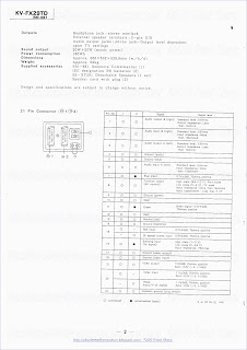


Hinton, “Character rounding for the Wireless Word Teletex Decoder,” Wireless World, Nov. 1978, pp. 49-53, vol. 84 No. 1515, IPC Business Press, United Kingdom.
Kruger, “Speicherfernsehen, Das Digitale Kennungssystem ZPS,” Proceedings 9th International Congress Microelectroncis, pp. 39-45.
“Fernsehempfang rund um die Uhr” Funk Technik, Mar. 1981, vol. 36.
“Method for the Transmission of Additional Information,” German Patent Application submitted by Blaupunkt Werke GMBH, filed May 31, 1980.
“Eine Neue Generation Mikroprozessorgesteuerter Datensender Und -Empfänger Für Alle Varianten Der Datenübertragung in Der V-Lücke Des Fernsehisgnals”, A. Ebner and K. Schuster, Rundfunktechnische Mitteilungen, vol. 26, No. 5, pp. 215-220.
“A Novel Television Add-On Data Communication System”, Jan. 1974, Patrick T. King, Society of Motion Picture and Television Engineers Journal, vol. 83.
“Actual Two-Way Systems,” Ronald K. Jurgen, IEEE Spectrum, Nov. 1971.
“Additional Information Within the Television Signal”, Sep. 1970, R. A. O'Connor, Journal of the Society of Motion Picture and Television Engineers, vol. 79, No. 9, p. 824.
“Applications of Information Networks,” J.C.R. et al, Proceedings of the IEEE, vol. 66, No. 11, pp. 1330-1346, Nov. 1978.
“Automated Control Units for Advertising on Cable,” G. Morgan, Image Technology, vol. 68, No. 9, pp. 457, 460, Sep. 1986.
“Coded Information Within the Picture Area”, Feb.,1974, Wilton R. Holm, Society of Motion Picture and Television Engineers Journal, vol. 83.
“Color Decode a PCM NTSC Television Signal”, Jun. 1974, John P. Rossi, Society of Motion Picture and Television Engineers Journal, vol. 83.
“Comparison of Technology and Capital Costs of New Home Services,” Metin B. Akgun, IEEE Transactions on Cable Television, vol. CATV-5, No. 3, Jul. 1980.
“Codifica Numerica Del Segnale Sonoro—Interfaccia Per Gli Apparati Professionali”, Oct. 1985, M. Barbero and M. Occhiena, Elettronica e Telecomunicazi oni, vol. 34, No. 5, 9 pp. 209-216.
“Encryption-based security systems”, May 29, 1987-Jun. 1, 1987, Wechselberger, NCTA Convention Records pp. 148-152.
“Experiences with Piolot Projects in North America, Japan, and Europe”, 1977, Eds. W. Kaiser, H. Marko, and E. Witte, Two-Way Cable Television.
“Going for The Microcomputer Market with Commercial Telesoftware”, 1982, M. Shain, Viewdata 82.
“Hard encrypted video & audio television system”, Mar. 15, 1986-Mar. 18, 1986, Jeffers, Glaab 8&. Griffin, NCTA Convention Records pp. 232-234.
“Hybrid Addressability,” Stubbs & Holobinko, National Cable Television Association Convention, pp. 255-265, Jun. 3-6, 1984.
“Individualized Still-Picture Communication on a Two-Way Broad-Band CATV System,” Koji Maeda, IEEE Transactions on Communications, vol. Com-23, No. 1, Jan. 1975.
“Low Cost Interactive Home TV Terminal,” Stetten & Mason, National Cable Television Association Convention, pp. 49-53, Jul. 6-9, 1971.
“Measurement and Control of TV Transmitters,” Shelley and Smart, Society of Motion Picture and Television Engineers Journal, vol. 80, Nov. 1971.
“Off Premises Addressability,” Preschutti, National Cable Television Association Convention, pp. 48-57, Jun. 2-5, 1985.
“On Distributed Communications,” Paul Baran, The RAND Corporation, vols. 1-10.
“Operational Implementation of a Broadcast Television Frame Synchronizer”, Mar. 1975, Robert J. Butler , Society of Motion Picture and Television Engineers Journal, vol. 84.
“Pilot Two-Way CATV Systems,” Ernest K. Smith, IEEE Transactions on Communications, vol. COM-23, No. 1, Jan. 1975.
“Some Methods of Automatic Analysis of Television Test Signals”, Dec. 1971, R. H. Vivian, Society of Motion Picture and Television Engineers Journal, vol. 80.
“SRS El Segundo Interim Test Report,” Callais, National Cable Television Association Convention, pp. 384-407, May 14-17, 1972.
“Status Monitoring System,” Hale, National Cable Television Association Convention, . 153-158, 1974.
“Television Applications and Transmission of Digital Data in the Vertical Blanking Interval”, 1980, J. J. Lopinto ITC/USA/'80, International Telemetering Conference, p. 650, pp. 345-349.
“Television Central,” Society of Motion Picture and Television Engineers Journal, vol. 85, Oct. 1976.
“The Digital Video Effects System,” Patten, Society of Motion Picture and Television Engineers Journal, vol. 87, Apr. 1978.
“The Magnavox Premium TV System,” Forbes & Cooley, National Cable Television Association Convention, pp. 100-104, Jun. 17-20, 1973.
“The Subscriber Response System,” Durfee & Callais, National Cable Television Association Convention, pp. 28-48, Jul. 6-9, 1971.
“TV Frame Synchronizer,” Kano, et al., Society of Motion Picture and Television Engineers Journal, vol. 84, Mar. 1975.
“Two-Way Coax TV System Handles All Communication Needs,” George F. Benton, Communications News, Apr. 1975.
“Use of Low Frequency Bi-Directional Digital Transmission on Cable,” Ellis, National Cable Television Association Convention, pp. 38-45, Apr. 17-20, 1977.
“Videotex & Teletext,” Technical Panel, National Cable Television Association Convention, pp. 160-184, Jun. 12-15, 1983.
“Videotex Network,” J. Stynen and M. Keymolen, Revue HF, vol. 1, No. 12, pp. 413-424, 1981.
“Videotex Technologies,” Technical Panel, National Cable Television Association Convention, pp. 99-123, May 29-Jun. 1, 1981.
Das Digitales Fernsehkennungssystem ZPS, H. Eckhard Kruger, ntz Bd. 35 (1982) Helft 6 (“The Digital Television Identification System ZPS,” ntz, vol. 35, No. 6, 1982, pp. 368-376).
Digitales Kennungssystem ZPS, Dr. H. E. Krüger, Forderungsvorhaben TK 0054/3 (“Digital Identification System ZPS,” Dr. H. E. Krüger, Research Project TK 0054/3, Final Report, Oct. 1, 1978 to Oct. 31, 1979).
Hi-Ovis Development Project, M. Kawahata, Presented in Two-Way Cable Television, Experiences with Pilot Projects in North America, Japan and Europe, Proceedings of a Symposium Held in Munich, Apr. 27-29, 1977, pp. 135-142.
Kinghorn, J.R., 11/00/85, “Using Extensions to World System Teletext,” IEEE Transactions on Consumer Electronics, vol. CE-31, No. 4, pp. 661-666.
The Videotex and Teletext Handbook, Hurly et al., Harper and Row Publishers, Inc., 1985.
Two-Way Applications for Cable Television Systems in the '70s, Ronald K. Jurgen, Editor, IEEE Spectrum, Nov. 1971.
Vereinbarung ZVEI/ARD/ZDF ZUR ZRD/ZDF/ZVVEI—Tichtline “Video-Programm-System (VPS),” ARD/ZDF, Dec. 4, 1984 (Memorandum of Understanding ZVEI/ARD/ZDF on the ARD/ZDF/ZVEI Guideline for a ‘Video Programming System (VPS)’).
Videoprogrammsystem Der 2. Generation, Von Gunther Stacker, net 40 (1986), Heft 7/8 (“Second-Generation Video Programming Systems,” Von Gunther Stacker, net vol. 7/8 No. 40 (1986), pp. 311-315).
Videotext Programmiert Videoheimgerate (VPV), Gerhard Eitz, Karl-Ulrich Oberlies, Fundfunktechnische Mitteilungen, Jahrg. 30 (1986), H. 5 (“VCR Programming VIA Teletext”).
Videotext Programmiert Videorecorder, Von Gunther Hofmann, Andreas Neuman, Karl-Ulrich Oberlies and Eckhard Schadwinkel, Rundfunktech Mitteilunger, Jahrg. 26 (1982) H. 6 (“Videotext Programs Video Recorder”).
Videotext Und Bildschirmtext Mit Den LSI-Schaltungden SAA 5020, SAA 5030, SAA 5041 Und SAA 5051, Valvo, Technische Information fur die Industrie, Apr. 1980 (Videotext and Interactive Videotex With the LSI-Circuits SAA 5020, SAA 5030, SAA 5041 and SAA 5051).
Viewdata: A Public Information Utility, Second Edition, 1980, Dr. Adrian V. Stokes.
Wunschprogramm Aus Der Fernsehzeitschrift, Funkschau Dec. 1981, p. 6070 (“Recording Programs From the Program Guide,” Funkschau Dec. 1982, pp. 60-70).
James, A., “ORACLE—Broadcasting the Written Word,” Wireless Word, Jul. 1975.
Carne, E. Bryan, “The Wired Household,” IEEE Spectrum, Oct. 1979, p. 61-66.
McKenzie, G.A., “Oracle—an Information Broadcasting Service Using Data Transmission in the Vertical Interval,” Journal of the SMPTE, vol. 83, No. 1, Jan. 1974, pp. 6-10.
Edwardson, S.M., “CEEFAX: A Proposed New Broadcasting Service,” Journal of the SMPTE, Jan. 1974, p. 14-19.
J. Chiddix, “Automated Videotape Delay of Satellite Transmissions,” Satellite Communications Magazine, May 1978 (reprint—2 pages).
J. Chiddix, “Tape Speed errors in Line-Locked Videocassettes Machines For CATV Applications,” TVC, Nov. 1977 (reprint—2 pages).
CRC Electronics, Inc. Product Description, “Model TD-100—Time Delay Videotape Controller,” 2 pages.
CRC Electronics, Inc., Net Price List—Mar. 1, 1980 (TD-100 Time Delay Videotape Controller), 1 page.
CRC Electronics, Inc. Product Description, “Model P-1000 Videocassette Programmer,” 4 pages.
CRC Electronics, Inc., Net Price List—Jul. 31, 1981 (P-1000 Video Machine Programmer), 1 page.
Tunmann, E.O. et al. (Tele-Engineering Corp.), “Microprocessor for CATV Systems,” Cable 78— Technical Papers, National Cable Television Association 27th Annual Convention, New Orleans, LA, Apr. 30-May 3, 1978 (“Cable 78”), pp. 70-75.
Vega, Richard L. (Telecommunications Systems, Inc.), “From Satellite to Earth Station to Studio to S-T-L to MDS Transmitter to the Home; Pay Television Comes to Anchorage, Alaska,” Cable 78, pp. 76-80.
Wright, James B. et al. (Rockford Cablevision, Inc.), “The Rockford Two-Way Cable Project: Existing and Projected Technology,” Cable 78, pp. 20-28.
Fannetti, John D. et al. (City of Syracuse), “The Urban Market: Paving the Way for Two-Way Telecommunications,”Cable 78, pp. 29-33.
Schnee Rolf M. et al. (Heinrich-Hertz-Institut Berlin (West)), “Technical Aspects of Two-Way CATV Systems in Germany,” Cable 78, pp. 34-41.
Dickinson, Robert V.C. (E-Com Corporation), “A Versatile, Low Cost System for Implementing CATV Auxiliary Services,” Visions '79—Technical Papers, National Cable Television Association 28th Annual Convention, Las Vegas, NV, May 20-23, 1979, (“Vision '79”), pp. 65-72.
Evans, William E. et al. (Manitoba Telephone System), “An Intercity Coaxial Cable Electronic Highway,” Visions '79, pp. 73-79.
Schrock, Clifford B. (C.B. Schrock and Associates, Inc.), “Pay Per View, Security, and Energy Controls Via Cable: The Rippling River Project,” Visions '79, pp. 80-85.
Southworth, Glen (Colorado Video, Inc.), “Narrow-Band Video: The UPI ‘Newstime’ Technology,” Visions '79pp. 86-88.
Daly IV, Raymond E. (Computer Cablevision, Inc.), “Pontential Use of Microcomputers—The Threats to the Technical Personnel, Manufacturers And Owners,” Vision '79, pp. 124-126.
Grabenstein, James B. (Potomac Valley Television Co., Inc.), “System Design and Operation with ‘Basic’,” Visions '79 (Appendix B), p. 127.
Amell, Richard L. (Cox Cable Communications, Inc.), “Computer-Aided CATV System Design,” Visions '79, pp. 128-133.
Yoshino, Hirokazu et al. (Matsushita Electric Industrial Co., Ltd.), “Multi-Information System Using Fiber Optics,” Visions '79, pp. 134-137.
Albright, Thomas G. (Printer Terminal Communications Corporation), “Cable Service: A Data Distribution Link,” Visions of the 80's—Technical Papers, National Cable Television Association 29th Annual Convention, Dallas, TX, May 18-21, 1980 (“Visions of the 80's”), pp. 30-34.
Blineau, Joseph J. (Centre Commun d'Etudes de Télévision et Télécommunications), “Measuring Methods and Equipments for Data Packet Broadcasting,” Visions of the 80's, pp. 35-39.
Katz, Harold W. (Interactive Systems/3M), “Status Report on EIA Broadband Modem Standards,” Visions of the 80's, pp. 40-44.
Lopinto, John J. (Home Box Office), “Considerations for Implementing Teletext in the Cable System,” Visions of the 80's, pp. 45-48.
O'Brien, Jr., Thomas E. (General Instrument Corporation), “System Design Criteria of Addressable Terminals Optimized for the CATV Operator,” Visions of the 80's, pp. 89-91.
Ost, Clarence S. et al. (Electronic Mechanical Products Co.), “High-Security Cable Television Access System,” Visions of the 80's, pp. 92-94.
Bacon, John C. (Scientific-Atlanta, Inc.), “Is Scrambling the Only Way?,” Visions of the 80's, pp. 95-98.
Davis, Allen (Home Box Office), “Satellite Security,” Visions of the 80's, pp. 99-100.
Mannino, Joseph A. (Applied Date Research, Inc.), “Computer Applications in Cable Television,” Visions of the 80's, pp. 116-117.
Beck, Ann et al. (Manhattan Cable TV), “An Automated Programming Control System for Cable TV,” Visions of the 80's, pp. 122-127.
Schloss, Robert E. et al. (Omega Communications, Inc.), “Controlling Cable TV Head Ends and Generating Messages by Means of a Micro Computer,” Vision of the 80's, pp. 136-138.
Eissler, Charles O. (Oak Communications, Inc.), “Addressable Control,” Cable: '81 the Future of Communications—Technical Papers, National Cable Television Association 30th Annual Convention, Los Angeles, CA, May 29-Jun. 1, 1981 (“Cable: '81 ”), pp. 29-33.
Schoeneberger, Carl F. (TOCOM, Inc.), “Addressable Terminal Control Using the Vertical Interval,” Cable: '81, pp. 34-40.
Stern, Joseph L. (Stern Telecommunications Corporation), “Addressable Taps,” Cable: '81, p. 41.
Brown, Larry C. (Pioneer Communications of America), “Addressable Control—A Big First Step Toward the Marriage of Computer, Cable, and Consumer,” Cable: '81, pp. 42-46.
Grabowski, Ralph E. (VISIONtec), “The Link Between the Computer and Television,” Cable: '81, pp. 99-100.
Ciciora, Ph.D., W.S. (Zenith Radio Corporation), “Virtext & Virdata: Adventures in Vertical Interval Signaling,” Cable: '81, pp. 101-04.
Gilbert, Bill et al. (Texscan Corporation), “Automatic Status Monitoring for a CATV Plant,” Cable: '81 , pp. 124-128.
Ciciora, Walter et al., “An Introduction to Teletext and Viewdata with Comments on Compatibility,” IEEE Transactions on Consumer Electronics, vol. CE-25, No. 3, Jul. 1979, (“Consumer Electronics”), pp. 235-245.
Tanton, N. E. “UK Teletext— Evolution and Potential,” Consumer Electronics, pp. 246-250.
Bright, Roy D., “Prestel—The World's First Public Viewdata Service,” Consumer Electronics, pp. 251-255.
Bown, H.G. et al., “Telidon: A New Approach to Videotex System Design,” Consumer Electronics, pp. 256-268.
Chitnis, A.M. et al., “Videotex Services: Network and Terminal Alternatives,” Consumer Electronics, pp. 269-278.
Hedger, J. “Telesoftware: Home Computing Via Broadcast Teletext,” Consumer Electronics, pp. 279-287.
Crowther, G.O., “Teletext and Viewdata Systems and Their Possible Extension to Europe and USA,” Consumer Electronics,, pp. 288-294.
Gross, William S., “Info-Text, Newspaper of the Future,” Consumer Electronics, pp. 295-297.
Robinson, Gary et al., “‘Touch-Tone’ Teletext—A Combined Teletext-Viewdata System,” Consumer Electronics, pp. 298-303.
O'Connor, Robert A., “Teletext Field Tests,” Consumer Electronics, pp. 304-310.
Blank, John, “System and Hardware Considerations of Home Terminals With Telephone Computer Access,” Comsumer Electronics, pp. 311-317.
Plummer, Robert P. et al, “4004 Futures for Teletext and Videotex in the U.S.,” Consumer Electronics, pp. 318-326.
Marti, B. et al., The Antiope Videotex System, Consumer Electronics, pp. 327-333.
Frandon, P. et al, “Antiope LSI,” Consumer Electronics, pp. 334-338.
Crowther, G.O., “Teletext and Viewdata Costs As Applied to the U.S. Market,” Consumer Electronics, pp. 339-344.
Mothersole, Peter L., “Teletext Signal Generation Equipment and Systems,” Consumer Electronics pp. 345-352.
Harden, Brian, “Teletext/Viewdata LSI,” Consumer Electronics, pp. 353-358.
Swanson, E. et al., “An Integrated Serial to Parallel Converter for Teletext Application,” Consumer Electronics, pp. 359-361.
Neal, C. Bailey et al., “A Frequency-Domain Interpretation of Echoes and Their Effect on Teletext Data Reception,” Consumer Electronics, pp. 362-377.
Goyal, Shri K. et al., “Reception of Teletext Under Multipath Conditions,” Consumer Electronics, pp. 378-392.
Prosser, Howard F., “Set Top Adapter Considerations for Teletext,” Consumer Electronics, pp. 393-399.
Suzuki, Tadahiko et al., Television Receiver Design Aspects for Employing Teletext LSI, Consumer Electronics, pp. 400-405.
Baer, Ralph H., “Tele-Briefs—A Novel User-Selectable Real Time News Headline Service for Cable TV,” Consumer Electronics, pp. 406-408.
Sherry, L.A., “Teletext Field Trials in the United Kingdom,” Consumer Electronics, pp. 409-423.
Clifford, Colin, “A Universal Controller for Text Display Systems,” Consumer Electronics, pp. 424-429.
Barlow, “The Design of an Automatic Machine Assignment System”, Journal of the SMPTE, Jul. 1975, vol. 84, p. 532-537.
Barlow, “The Automation of Large Program Routing Switchers”, SMPTE Journal, Jul. 1979, Vol. 88, p. 493-497.
Barlow, “The Computer Control of Multiple-Bus Switchers”, SMPTE Journal, Sep. 1976, Vol. 85, p. 720-723.
Barlow, “The Assurance of Reliability”, SMPTE Journal, Feb. 1976, Vol. 85, p. 73-75.
Barlow, “Some Features of Computer-Controlled Television Station Switchers”,Journal of the SMPTE, Mar. 1972, vol. 81, p. 179-183.
Barlow et al., “A Universal Software for Automatic Switchers”, SMPTE Journal, Oct. 1978, vol. 87, p. 682-683.
Butler, “PCM-Multiplexed Audio in a Large Audio Routing Switcher”, SMPTE Journal, Nov. 1976, vol. 85, p. 875-877.
Dickson et al., “An Automated Network Center”, Journal of the SMPTE, Jul. 1975, Vol. 84, p. 529-532.
Edmondson et al., “Nbc Switching Central”, SMPTE Journal, Oct. 1976, Vol. 85, p. 795-805.
Flemming, “NBC Television Central—An Overview”, SMPTE Journal, Oct. 1976, Vol. 85, p. 792-795.
Horowitz, “CBS” New-Technology Station, WBBM-T, SMPTE Journal, Mar. 1978, vol. 87, p. 141-146.
Krochmal et al., “Television Transmission Audio Facilities at NBC New York”, SMPTE Journal, Oct. 1976, vol. 85, p. 814-816.
Kubota et al., “The Videomelter”, SMPTE Journal, Nov. 1978, Vol. 87, p. 753-754.
Mausler, “Video Transmission Video Facilities at NBC New York”, SMPTE Journal, Oct. 1976, vol. 85, p. 811-814.
Negri, “Hardware Interface Considerations for a Multi-Channel Television Automation System”, SMPTE Journal, Nov. 1976, vol. 85, p. 869-872.
Paganuzzi, “Communication in NBC Television Central”, SMPTE Journal, Nov. 1976, vol. 85, p. 866-869.
Roth et al., “Functional Capabilities of a Computer Control System for Television Switching”, SMPTE Journal, Oct. 1976, vol. 85, p. 806-811.
Rourke, “Television Studio Design—Signal Routing and Measurement”, SMPTE Journal, Sep. 1979, vol. 88, p. 607-609.
Yanney, Sixty-Device Remote-Control System for NBC's Television Central Project, SMPTE Journal, Nov. 1976, vol. 85, p. 873-877.
Young et al., “Developments in Computer-Controlled Television Switches”, Journal of the SMPTE, Aug. 1973, vol. 82, p. 658-661.
Young et al., “The Automation of Small Television Stations”, Journal of the SMPTE, Oct. 1971, vol. 80, p. 806-811.
Zborowski, “Automatic Transmission Systems for Television”, SMPTE Journal, Jun. 1978, vol. 87, p. 383-385.
“Landmark forms cable weather news network,” Editor & Publisher, (Aug. 8, 1981) p. 15.
“Broadcast Teletext Specification,” published jointly by British Broadcasting Corporation, Independent Broadcasting Authority, British Radio Equipment Manufacturers' Association (Sep. 1976), pp. 1-24.
“Colormax Cable captioning—16,000,000 Subs Need It!,” Colormax Electronic Corp. (advertisement), 3 pages.
“7609 Sat-A-Dat Decoder/Controller,” Group W Satellite Communications (advertisement) 2 pages.
“Teletext Timing Chain Circuit (SAA5020),” (Aug. 1978), pp. 109.
“Teletext Video Processor (SAA 5030),” Mullard (Dec. 1979), pp. 1-9.
“Video Text Decoder Systems (Signetics)”, Phillips IC Product Line Summary (May 1981), pp. 15-16.
“Teletext Acquisition and Control Circuit (SAA5040 Series),” Mullard (Jun. 1980), pp. 1-16.
“Asynchronous Data Transmission System Series 2100 Vidata,”Wagener Communications, Inc. (advertisement), 2 pages.
“Zenith VIRTEXTTM . . . Vertical Interval Region Text and Graphics,” Zenith Radio Corporation (flyer), 7 paged.
Anon, “Television Network Automated by Microcomputer-Controlled Channels,” Computer Design, vol. 15, No. 11, (Nov. 1976), pp. 50, 59, 62, 66 and 70.
Kinik, et al., “A Network Control System for Television Distribution by Satellite,” Journal of the SMPTE, Feb. 1975, vo. 84 No. 2, pp. 63-67.
Chiddix, “Videocassette Banks Automate Delayed Satellite Programming,” Aug. 1978, TV Comunications, pp. 38-39.
Curnal, et al., “Automating Television Operating Centers,” Bell Laboratories Record, Mar. 1978, pp. 65-70.
Baran, Paul (Packetcable Inc.), “Packetcable: A New Interactive Cable System Technology,” Cable '82—Technical Papers, National Cable Television Association 31st Annual Convention, Las Vegas, NV, May 3-5, 1982 (“CABLE '82”), pp. 1-6.
Tunmann, Ernest O. (Tele-Engineering Corporation), “Two-Way Cable TV Technologies,” Cable '82, pp. 7-15.
Dickinson, Robert V.C. (E-COM Corporation), “Carriage of Multiple One-Way and Interactive Service on CATV Networks,” Cable '82, pp. 16-21.
McNamara, R.P. et al. (Sytek, Incorporated), “MetroNet: an Overview of a CATV Regional Data Network,” Cable '82, pp. 22-31.
Eissler, Charles (Oak Communications Systems), “Addressable Control for the Small System,” Cable '82, pp. 32-36.
Mesiya, M.F. et al. (Times Fiber Communications, Inc.), “Mini-Hub Addressable Distribution System for Hi-Rise Application,” Cable '82, pp. 37-42.
Thomas, William L. (Zenith Radio Corporation), “Full Field Tiered Addressable Teletext,” Cable '82, pp. 44 46.
Langley, Don et al. (University of Cincinnati and Rice-Richter Associates), “Interactive Split Screen Teleconferencing,” Cable '82, pp. 47-50.
Klare, Stephen W. (Scientific—Atlanta), “Bandwidth-Efficient, High-Speed Modems for Cable Systems,” Cable '82, pp. 72-78.
Jubert, Jay (Wang Laboratories, Inc.), “Wangnet, a Cable-Based Localnet,” Cable '82, pp. 79-81.
Switzer, I. (Cable America, Inc.), “Cable TV Advances and TV Receiver Compatibility Problems,” Cable '82, pp. 114-118.
Skrobko, John (Scientific-Atlanta Incorporated), “Improving CATV System Reliability with Automatic Status Monitoring and Bridger Switching,” Cable '82, pp. 133-137.
Dahlquist, John (Jerrold Division, General Instrument Corporation), “Techniques for Improving Continuity of Service in a CATV Distribution System,” Abstract, Cable '82, p. 138.
Polishuk, Paul Dr. (Information Gatekeepers, Inc.) “Present Status of Fiber Optics Technology and its Impact on the CATV Industry,” Cable '82, pp. 142-147.
Dufresne, Michel (Videotron Communications LTEE), “New Services: an Integrated Cable Networks's Approach,” Cable '82, pp. 156-160.
Stanton, Gary W. (Southern Satellite Systems), “Downloading and Addressing via Teletext,” Cable '82, pp. 161-165.
Goldberg, Efrem I. (GTE Laboratories Incorporated), “Videotex on Two-Way Cable Television Systems—Some Technical Considerations,” Cable '82, pp. 166-174.
Noirel, Yves (CCETT/Rennes, France), “Abstract of paper entitled Data Broadcasting: “Didon” and “Diode” Protocols,” Cable '82, pp. 175-179.
von Meister, William F. (Digital Music Company), “The Home Music Store,” Cable '82, pp. 180-182.
Brown, Jr., Robert R. (Cima Telephone and Television), “Inter Bridger Trunking for Information Services,” Cable '82, pp. 183-189.
Alvord, Charles, Dr. (Communications Technology Management, Inc.), “Creating Standards for Interconnect Systems,” Cable '82, pp. 190-196.
Schrock, Clifford B. (Cable Bus Systems Corporation), “Can Noise and Ingress Coexist with Two-Way Services?,” Cable '82, pp. 205-209.
The Weather Channel, “The Weather Star Satellite Transponder Addressable Receiver,” Operation/Installation Manual, Rev. 01.5/82.
Lafayette, Jon, “TV ad monitor system starts tests here Mon.,” New York Post, Oct. 18, 1985, p. 63.
Jones, Stacy V., “Patents/Monitoring Display of TV Ads,” The New York Times, Oct. 19, p. 34.
Remley, F.M., “Television Technology,” SMPTE Journal, May 1982, pp. 458-462.
Proposed American National Standard, “Electrical and Mechanical Characteristics for Digital Control Interface,” SMPTE Journal, Sep. 1982, pp. 888-897.
Zaludek, Jerry P., “Videotape—Past, Present, and Future,” SMPTE Journal, Apr. 1982, pp. 356-360.
Kary, Michael Loran, “Video-Assisted Film Editing System,” SMPTE Journal, Jun. 1982, pp. 547-551.
Glover, S. “Automatic Switching at the Edmonton Television Studios,” SMPTE Journal, Nov. 1966, vol. 75, pp. 1089-1092.
Barlow, M.W.S., “The Remote Control of Multiplexed Telecine Chains,” SMPTE Journal, Apr. 1971, vol. 80, pp. 270-275.
Campbell, Keith D., “An Automated Video-Tape Editing System,” Journal of the SMPTE, Mar. 1970, vol. 79, pp. 191-194.
Bonney, R.B. et al., “A Proposed Standard Time and Control Code for Video-Tape Editing,” Journal of the SMPTE, Mar. 1970, vol. 79, pp. 186-190.
Barlow, M., Letter to the Editor, “Re: Coding and Packaging Film for Broadcasting,” Journal of the SMPTE, Oct. 1969, vol. 78, p. 889.
Barlow, M., Letter to the Editor, “Re: Automation of Telecine Equipment,” Journal of the SMPTE, Apr. 1970, vol. 79, pp. 345-346.
Matley, J. Brian, “A Digital Framestore Synchronizer,” SMPTE Journal, Jun. 1976, vol. 85, pp. 385-388.
Connolly, W.G. et al., “The Electronic Still Store: A Digital System for the Storage and Display of Still Pictures,” SMPTE Journal, Aug. 1976, vol. 85, pp. 609-613.
Sadashige, K., “Overview of Time-Base Correction Techniques and Their Applications,” SMPTE Journal, Oct. 1976, vol. 85, pp. 787-791.
Siocos, C.A., “Satellite Technical and Operational Committee—Television (STOC-TV) Guidelines for Waveform Graticules,” SMPTE Journal, Nov. 1976, vol. 85, pp. 878-879.
“Index to Subjects—Jan.-Dec. 1976 • vol. 85,” 1976 Index to SMPTE Journal, SMPTE Journal, vol. 85, pp. I-5 to I-13, I-15.
Rodgers, Richard W., “Design Considerations for a Transmission and Distribution System for SMPTE Time-Code Signals,” SMPTE Journal, Feb. 1977, vol. 86, pp. 69-70.
Allan, J.J., III, et al., “A Computer-Controlled Super-8 Projector,” SMPTE Journal, Jul. 1977, vol. 86, pp. 488-489.
“Index to Subjects—Jan.-Dec. 1977 • vol. 86,” 1977 Index to SMPTE Journal, SMPTE Journal, vol. 86, pp. I-5 to I-14.
Hamalainen, KJ., “Videotape Editing Systems Using Microprocessors,” SMPTE Journal, Jun. 1978, Vol. 87, pp. 379-382.
McCoy, Reginald F.H., “A New Digital Video Special-Effects Equipment,” SMPTE Journal, Jan. 1978, vol. 87, pp. 20-23.
Leonard, Eugene, “Considerations Regarding the Use of Digital Data to Generate Video Backgrounds,” SMPTE Journal, Aug. 1978, vol. 87, pp. 499-504.
Swetland, George R., “Applying the SMPTE Time and Control Code to Television Audio Post Production,” SMPTE Journal, Aug. 1978, vol. 87, pp. 508-512.
Moore, J.K., et al., “A Recent Innovation in Digital Special Effects, The CBS ‘Action Track’ System,” SMPTE Journal, Oct. 1978, vol. 87, pp. 673-676.
Connolly, William G., “Videotape Program Production at CBS Studio Center,” SMPTE Journal, Nov. 1978, vol. 87, pp. 761-763.
Nicholls, William C., “A New Edit Room Using One-Inch Continuous-Field Helical VTRs,” SMPTE Journal, Nov. 1978, vol. 87, pp. 764-766.
“Index to vol. 87 Jan.-Dec. 1978,” SMPTE Journal, Part II to Jan. 1979 SMPTE Journal, pp. I-1, I-4 to I-14.
Wetmore, R. Evans, “System Performance Objectives and Acceptance Testing of the Public Television Satellite Interconnection System,” SMPTE Journal, Feb. 1979, vol. 88, pp. 101-111.
Bates, George W., “Cut/Lap: A New Method for Programmable Fades and Soft Edit Transitions Using a Single Source VTR,” SMPTE Journal, Mar. 1979, vol. 88, pp. 160-161.
Douglas, W. Gordon, “PBS Satellite Interconnection Technical Operations and Maintenance,” SMPTE Journal, Mar. 1979, vol. 88, pp. 162-163.
Oliphant, Andrew et al., “A Digital Telecine Processing Channel,” SMPTE Journal, Jul. 1979, vol. 88, pp. 474-483.
Bates, George W. et al., “Time Code Error Correction Utilizing a Microprocessor,” SMPTE Journal, Oct. 1979, vol. 88, pp. 712-715.
Geise, Heinz-Dieter, “The Use of Microcomputers and Microprocessors in Modern VTR Control,” SMPTE Journal, Dec. 1979, vol. 88, pp. 831-834.
“Index to Subjects—Jan.-Dec. 1979 • vol. 88,” 1979 Index to SMPTE Journal, SMPTE Journal, vol. 88, pp. I-4 to I-10.
“Advanced Transmission Techniques,” SMPTE Journal, Report on the 121st Technical Conference, Jan. 1980, vol. 89, pp. 31-32.
“Anderson: Progress Committee Report for 1979—Television,” SMPTE Journal, May 1980, vol. 89, pp. 324-328.
SMPTE Journal, May 1980, vol. 89, p. 391, no title.
“The TCR-119 Reader,” Gray Engineering Laboratories, SMPTE Journal, May 1980, vol. 89, p. 438. (advertisement).
Hopkins, Robert S., Jr., “Report of the Committee on New Technology,” SMPTE Journal, Jun. 1980, vol. 89, pp. 449-450.
Limb, J.O. et al., “An Interframe Coding Technique for Broadcast Television,” SMPTE Journal, Jun. 1980, vol. 89, p. 451.
“Preliminary List of Papers,” SMPTE Journal, Sep. 1980, vol. 89, p. 677.
Davis, John T., “Automation of a Production Switching System,” SMPTE Journal, Oct. 1980, vol. 89, pp. 725-727.
“Video Tape Recording Glossary,” SMPTE Journal, Oct. 1980, vol. 89, p. 733.
Advertisement, “CTVM 3 series of Barco master control color monitors”, “Barco TV Modulator, Model VSBM 1/S”, “VICMACS Type 1724 Vertical Interval Machine Control System”, “Videotape Editing Controllers by US JVC Corp., RM-70U, RM-82U, RM-88U”, SMPTE Journal, Oct. 1980, Vol. 89, p. 820 et seq.
Ciciora, Walter, “Teletext Systems: Considering the Prospective User,” SMPTE Journal, Nov. 1980, vol. 89, pp. 846-849.
Hathaway, R.A. et al., “Development and Design of the Ampex Auto Scan Tracking (AST) System,” SMPTE Journal, Dec. 1980, vol. 89, p. 931.
Connor, Denis J., “Network Distribution of Digital Television Signals,” SMPTE Journal, Dec. 1980, vol. 89, pp. 935-938.
“Index to Subjects—Jan.-Dec. 1980 • vol. 89,” 1980 Index to SMPTE Journal, SMPTE Journal, pp. I-5 to I-11.
“Index to SMPTE-Sponsored American National Standards, Society Recommended Practices, and Engineering Committee Recommendations,” 1980 Index to SMPTE Journal, SMPTE Journal, pp. I-15 to I-20.
Table of Contents, SMPTE Journal, Feb. 1981, vol. 90, No. 2, 1 page.
Table of Contents, SMPTE Journal, Mar. 1981, vol. 90, No. 3, 1 page.
Table of Contents, SMPTE Journal, Apr. 1981, vol. 90, No. 4,1 page.
Table of Contents, SMPTE Journal, May 1981, vol. 90, No. 5, 1 page.
“Television,” SMPTE Journal, May 1981, pp. 375-379.
Table of Contents, SMPTE Journal, Jan. 1981, vol. 90, No. 1,1 page.
Table of Contents, SMPTE Journal, Jun. 1981, vol. 90, No. 6, 1 page.
Table of Contents, SMPTE Journal, Jul. 1981, vol. 90, No. 7,1 page.
Table of Contents, SMPTE Journal, Aug. 1981, vol. 90, No. 8, 1 page.
“American National Standard” “time and control code for video and audio tape for 525-line/ 60-field television systems,” SMPTE Journal, Aug. 1981, pp. 716-717.
Table of Contents, SMPTE Journal, Sep. 1981, vol. 90, No. 9, 1 page.
“Proposed SMPTE Recommended Practice” “Vertical Interval Time and Control Code Video Tape for 525-Line/ 60-Field Television Systems,” SMPTE Journal, Sep. 1981, pp. 800-801.
Table of Contents, SMPTE Journal, Oct. 1981, vol. 90, No. 10, 1 page.
Kaufman, Paul A. et al., “The Du Art Frame Count Cueing System,” SMPTE Journal, Oct. 1981, pp. 979-981.
“American National Standard” “dimensions of video, audio and tracking control records on 2-in video magnetic tape quadruplex recorded at 15 and 7.5 in/ s,” SMPTE Journal, Oct. 1981, pp. 988-989.
Table of Contents, SMPTE Journal, Nov. 1981, vol. 90, No. 11, 1 page.
Table of Contents, SMPTE Journal, Dec. 1981, vol. 90, No. 12, 1 page.
Powers, Kerns H., “A Hierarchy of Digital Standards for Teleproduction in the Year 2001,” SMPTE Journal, Dec. 1981, pp. 1150-1151.
“Application of Direct Broadcast Satellite Corporation for a Direct Broadcast Satellite System,” Before the Federal Communications Commission, Washington, D.C., Jul. 16, 1981.
Rice, Michael, “Toward Enhancing the Social Benefits of Electronic Publishing,” Report of an Aspen Institute Planning Meeting, Communications and Society Forum Report, Feb. 25-26, 1987.
Rice, Michael, “Toward Improved Computer Software for Education and Entertainment in the Home,” Report of an Aspen Institute Planning Meeting, Communications and Society Forum Report, Jun. 3-4, 1987.
Gano, Steve, “Teaching ‘real world’ systems,” 1 page, 1987.
Pollack, Andrew, “Putting 25,000 Pages on a CD,” New York Times, 1 page, Mar. 4, 1987.
Gano, Steve, “A Draft of a Request for Proposals Concerning the Adoption of Computer Technology in the Home,” Jan. 1988, Draft © 1987 Steve Gano.
COMSAT, “Communications Satellite Corporation Magazine,” No. 7, 1982.
COMSAT, “Satellite to Home Pay Television,” no date.
COMSAT, “Annual Report 1981.”
“Comsat's STC: Poised for blastoff into TV's space frontier,” Broadcasting, Feb. 22, 1982, pp. 38-45.
Taylor, John P., “Comsat bid to FCC for DBS authorization: Questions of finances, ‘localism,’ monopoly,” Television/Radio Age, May 4, 1981, pp. 42-44 and 80-81.
Taylor, John P., “Fourteen DBS authorization applications to FCC differ greatly in both structure and operations,” Television/Radio Age, Oct. 5, 1981, pp. 40-42 and 116-119.
Taylor, John P., “Comsat bid to FCC for DBS authorization: Is direct broadcasting the wave of the future?”, Television/Radio Age, Mar. 23, 1981, pp. A-22-24 and A-26 and A-28-31.
“At Sequent Computer, One Size Fits All,” Business Week, Sep. 17, 1984, 1 page.
Hayashi, Alden, M., “Can Logic Automation model its way to success?”, Electronic Business, Aug. 1, 1986, 1 page.
“Imager monitors the bloodstream,” High Technology, Mar. 1987, 1 page.
Merritt, Christopher R.B., M.D., “Doppler blood flow imaging: integrating flow with tissue data,” Diagnostic Imaging, Nov. 1986, pp. 146-155.
Eisenhammer, John, “Will Europe's Satellite TV Achieve Lift-Off?”, Business, Aug. 1986, pp. 56-60.
Hayes, Thomas C., “New M.C.C. Chief's Strategy: To Speed Payoff on Research,” The New York Times, Jun. 24, 1987, 2 pages.
Collins, Glenn, “For Many, a Vast Wasteland Has Become a Brave New World,” New York Times, no date, 2 pages.
Gleick, James, “U.S. Is Lagging on Forecasting World Weather,” The New York TimesFeb. 15, 1987, 2 pages.
Browning, E.S., “Sony's Perseverance Helped It Win Market for Mini-CD Players,” Wall Street Journal, Feb. 27, 1986, 2 pages.
Dragutsky, Paula, “Data in the bank is booming biz,” New York Post, Apr. 29, 1985, 1 page.
Wayne, Leslie, “Dismantling the Innovative D.R.I.,” The New York Times, Dec. 16, 1984, 2 pages.
Sanger, David E., “A Computer Full of Surprises,” The New York Times, May 8, 1987, 2 pages.
Hoffman, Paul, “The Next Leap in Computers,” The New York Times Magazine, Dec. 7, 1986, 6 pages.
Taylor, Thayer C., “Laptops and the Sales Force: New Stars in the Sky,” pp. 81-84.
Parker, Edwin B., “Satellite micro earth stations—a small investment with big returns,” Data Communications, Jan. 1983, 5 pages.
“Micro Key System,” Video Associates Labs, product description.
“SMPTE Journal Five-Year Index 1971-1975,” SMPTE Journal.
“SMPTE Journal Five-Year Index 1976-1980,” SMPTE Journal.
“SMPTE Journal Five-Year Index 1981-1985,” SMPTE Journal, vol. 95, No. 1, Jan. 1986.
“SMPTE Journal Five-Year Index 1986-1990,” SMPTE Journal, vol. 100, No. 1, Jan. 1991.
“Annual Index 1982,” SMPTE Journal, vol. 91, Jan.-Dec. 1982, pp. 1253-1263.
“Highlights, SMPTE, The 124th SMPTE Conference,” SMPTE Journal, Jan. 1983, p. 3.
SMPTE Journal, Jan. 1983, pp. 64, 69-70, 87-90, 92-98.
“Highlights, SMPTE,” SMPTE Journal, Feb. 1983, p. 163.
“Highlights, SMPTE,” SMPTE Journal, Mar. 1983, p. 267.
“Highlights, SMPTE,” SMPTE Journal, Apr. 1983, p. 355.
Thomas, L. Merle, “Television,” SMPTE Journal, Apr. 1983, pp. 407-410.
“Highlights, SMPTE,” SMPTE Journal, May 1983, p. 547.
“Highlights, SMPTE,” SMPTE Journal, Jun. 1983, p. 627.
“Highlights, SMPTE,” SMPTE Journal, Jul. 1983, p. 715.
“Highlights, SMPTE,” SMPTE Journal, Aug. 1983, p. 803.
Tooms, Michael S. et al., “The Evolution of a Comprehensive Computer Support System for the Television Operation,” SMPTE Journal, Aug. 1983, pp. 824-833.
“Highlights, SMPTE,” SMPTE Journal, Sep. 1983, p. 907.
“Highlights, SMPTE,” SMPTE Journal, Oct. 1983, p. 1027.
“Highlights, SMPTE,” SMPTE Journal, Nov. 1983, p. 1173.
“Highlights, SMPTE,” SMPTE Journal, Dec. 1983, p. 1269.
“Index to Subjects—Jan.-Dec. 1983 • vol. 92,” Annual Index 1983, SMPTE Journal, pp. 1385-1391.
“Highlights, SMPTE,” SMPTE Journal, Jan. 1984, p. 3.
“Index to Subjects—Jan.-Dec. 1984 • vol. 93,” Annual Index 1984, SMPTE Journal, pp. 1211-1217.
“Highlights, SMPTE,” SMPTE Journal, Jan. 1985, p. 3.
Barlow, Michael W.S., “Application of Personal Computers in Engineering,” SMPTE Journal, Jan. 1985, pp. 27-30.
“Television Systems and Broadcast Technology,” SMPTE Journal, Jan. 1985, pp. 172-175.
“Highlights, SMPTE,” SMPTE Journal, Feb. 1985, p. 181.
Day, Alexander G., “From Studio to Home—How Good is the Electronic Highway?”, SMPTE Journal, Feb. 1985, pp. 216-217.
“Highlights, SMPTE,” SMPTE Journal, Mar. 1985, p. 265.
“Proposed SMPTE Recommended Practice, Storage of Edit Decision Lists on 8-in. Flexible Diskette Media,” SMPTE Journal, Mar. 1985, pp. 353-354.
McCroskey, Donald C., “Television,” SMPTE Journal, Apr. 1985, pp. 382-395.
“Highlights, SMPTE,” SMPTE Journal, Apr. 1985, p. 361.
SMPTE Journal, Apr. 1985, pp. 366-368, 473-478.
“Highlightsd SMPTE,” SMPTE Journal, May 1985, p. 545.
Morii, Yutaka, et al., “A New Master Control System for NHK's Local Stations,” SMPTE Journal, May 1985, pp. 559-564.
Kuca, Jay, et al., “A Fifth-Generation Routing Switcher Control System,” SMPTE Journal, May 1985, pp. 566-571.
“Highlights, SMPTE,” SMPTE Journal, Jun. 1985, p. 641.
“Highlights, SMPTE,” SMPTE Journal, Jul. 1985, p. 721.
Busby, E.S., “Digital Component Television Made Simple,” SMPTE Journal, Jul. 1985, pp. 759-762.
“Highlights, SMPTE,” SMPTE Journal, Aug. 1985, p. 801.
Rayner, Bruce, “High-Level Switcher Interface Improves Editing Techniques,” , SMPTE Journal, Aug. 1985, pp. 810-813.
Hayes, Donald R., “Vertical-Interval Encoding for the Recordable Laser Videodisc,” SMPTE Journal, Aug. 1985, pp. 814-820.
“SMPTE Recommended Practice, Video Record Parameters for 1-in Type C Helical-Scan Video Tape Recording,” SMPTE Journal, Aug. 1985, pp. 872-873.
“Proposed SMPTE Recommended Practice, Time and Control Codes for 24, 25, or 30 Frame-Per-Second Motion-Picture Systems,” SMPTE Journal, Aug. 1985, pp. 874-876.
“Proposed SMPTE Recommended Practice, Data Tracks on Low-Dispersion Magnetic Coatings on 35-mm Motion-Picture Film,” SMPTE Journal, Aug. 1985, pp. 877-878.
“Highlights,” SMPTE Journal, Sep. 1985, p. 881.
“Proposed SMPTE Recommended Practice, Control Message Archtecture,” SMPTE Journal, Sep. 1985, pp. 990-991.
“Proposed SMPTE Recommended Practice, Tributary Interconnection,” SMPTE Journal, Sep. 1985, pp. 992-995.
“Highlights,” SMPTE Journal, Oct. 1985, p. 1001.
Zimmerman, Frank, “Hybrid Circuit Construction for Routing Switchers,” SMPTE Journal, Oct. 1985, pp. 1015-1019.
“Highlights,” SMPTE Journal, Nov. 1985, p. 1155.
Sabatier, J., et al., “The D2-MAC-Packet System for All Transmission Channels,”SMPTE Journal, Nov. 1985, pp. 1173-1179.
“Highlights,” SMPTE Journal, Dec. 1985, p. 1243.
Shiraishi, Yuma, “History of Home Videotape Recorder Development,” SMPTE Journal, Dec. 1985, pp. 1257-1263.
“Index to Subjects—Jan.-Dec. 1985 • vol. 94,” Annual Index 1985, SMPTE Journal, pp. 1351-1357.
“Highlights,” SMPTE Journal, Jan. 1986, p. 3.
“Proposed American National Standard for component digital video recording—19-mm type D-1 cassette— tape cassette,” SMPTE Journal, Mar. 1986, pp. 362-363.
“Index to SMPTE-Sponsored American National Standards and Society Recommended Practices and Engineering Guidelines,” Smpte Journal, Annual Index 1987, pp. 1258, 1260-1262.
Rice, Philip, et al., “Development of the First Optical Videodisc,” SMPTE Journal, Mar. 1982, pp. 277-284.
Kubota, Yasuo, “The Videomelter,” SMPTE Journal, vol. 87, Nov. 1978, pp. 753-754.
“USTV Direct Satellite to Home Television Service,” General Instrument News Release, Aug. 1982.
“Second Senior Executive Conference on Productivity Improvement,” SALT, Society for Applied Learning Technology, Dec. 4-6, 1986.
“New Publications for 1987 from The Videodisc Monitor,” advertisement, 2 pages.
“The Videodisc Monitor,” vol. IV: No. 10, Oct. 1986.
“The Videodisc Monitor,” vol. IV: No. 12, Dec. 1986.
Smith, Charles C., “Computer Update” “Program Notes,” TWA Ambassador, Sep. 1982, pp. 74-90.
Harrar, George, “Opening Information Floodgates,” American Way, Oct. 1982, pp. 53-56.
“Publishers Go Electronic,” Business Week, Jun. 11, 1984, pp. 84-97.
“Serious Software Helps the Home Computer Grow Up,” Business Week, Jun. 11, 1984, pp. 114-118.
“Videoconferencing: No Longer Just a Sideshow,” Business Week, Nov. 12, 1984, pp. 116-120.
“Ratings War,” Forbes, Aug. 1, 1983, 1 page.
Kindel, Stephen, “Pictures at an exhibition,” Forbes, Aug. 1, 1983, pp. 137-139.
“Merrill Lynch and IBM Form Joint Venture to Market Financial Data Systems and Services,” News Release, Mar. 1984, 2 pages.
Branch, Charles, “Text Over Video,” PC World, Dec. 1983, pp. 202-210.
“Window on the World” “The Home Information Revolution,” 1981, Business Week, Jun. 29, 1981, pp. 74-83.
“Correspondence School Via Computer Is Planned,” The New York Times, Sep. 13, 1983, 1 page.
“‘Smart’ Digital TV Sets May Replace The Boob Tube,” Business Week, Sep. 26, 1983, p. 160, 2 pages.
“Round Two for Home Computer Makers,” Business Week, Sep. 19, 1983, pp. 93-95.
“High Technology,” Business Week, Jan. 11, 1982, pp. 74-79.
Kneale, Dennis, “Stations That Show Only Ads Attract a Lot of TV Watchers,” The Wall Street Journal, Sep. 23, 1982, 1 page.
“Video Kitchen” “Commercial Prospects for Food Data-Base Management,” Prospectus for a Multiclient Study from American Information Exchange, 1982.
I/Net Corporation, Company Brochure.
Diamond, David, “Why Television's Business Programs Haven't Turned a Profit,”The New York Times, Jun. 16, 1985, pp. F10-F11.
Tagliabue, John, “ITT's Key. West German Unit,” The New York Times, Apr. 29, 1985, p. D8.
Tagliaferro, John, “Tag Lines,” 1982, 1 page.
“PBS Project With Merrill,” newsarticle, Apr. 4, 1983.
“Merrill Lynch sinks $4M into FNN's Data Cast service,” Cable Vision, Mar. 11, 1985, p. 23.
“Merrill Lynch bullish on new data service,” Electronic Media, Feb. 28, 1985, p. 4.
“Merrill Lynch Plans Stock-Quote Service Linked to IBM's PC,” The Wall Street Journal, Mar. 21, 1984, p. 60.
Sanger, David E., “Public TV Joins Venture to Send Finance Data to Computer Users,” The New York Times, Feb. 21, 1985, pp. 1 and D8.
Dolnick, Edward, “Inventing The Future,” The New York Times Magazine, Aug. 23, 1987.
“Everything you've always wanted to know about TV Ratings,” A.C. Nielsen Company, brochure, 1978.
“Management With The Nielsen Retail Index System,” A.C. Nielsen Company, 1980.
Pollack, Andrew, “Computer Programs as University Teachers,” The New York Times, 4 pages.
“Business Television” “Changing the Way America Does Business,” PSN, 1986.
Merrell, Richard G., “TAC-Timer,” 1986 NCTA Technical Papers, 1986, pp. 203-206.
“Universal Remote Control,” Radio Shack, Owner's Manual, 4 pages.
Long, Michael, E., “The VCR Interface,” 1986 NCTA Technical Papers, 1986, pp. 197-202.
“Flexible programmieren mit. VPS,” Funkschau, (German publication), 1985. (translation provided).
Chase, Scott, “Corporate Satellite Networks No Longer A Luxury But Rather A Necessity,” Via Statellite, Jul. 1987, pp. 18-21.
Diamond, Sam, “Turning Television Into A Business Tool,” High Technology, Apr. 1987, 2 pages.
“The Portable Plus Personal Computer,” Hewlett-Packard, advertisement, Mar. 1986.
“The Portable Plus for Professionals in Motion,” Hewlett-Packard, advertisement, Jul. 1985.
“KBTV Kodak Business TeleVision,” Kodak, brochure, Sep. 1987.
“Broadway Video,” Brochure, Feb. 1987.
“Digital TV set to burst on U.S. mart,” New York Post, 2 pages.
Prospectus, VIKONICS, Inc., Jul. 14, 1987.
Prospectus, DIGITEXT, Inc., Feb. 27, 1986.
Prospectus, Color Systems Technology, Inc., Aug. 13, 1986.
Prospectus, Cheyenne Software, Inc., Oct. 3, 1985.
1986 Annual Report, the Allen Group Inc.
Wilson, Donald H., “A Process for Creating a National Legal Computer Research Service in The United States,” remarks at the conference on World Peace Through World Law and World Assembly of Judges, Belgrade Yugoslavia, Jul. 23, 1971.
Pollack, Andrew, “Teletext is Ready for Debut,” The New York Times, Feb. 18, 1983, 2 pages.
“Sunny Outlook for Landmark's John Wynne; Landmark Communications Inc.,” Broadcasting, Lexis-Nexis, Jul. 27, 1987.
“Applications Information VCR-3001A Universal Videocassette Control Module,” Channelmatic, Inc., product description, 5 pages, Mar. 1984.
Killion, Bill, “Advertising,” SAT Guide, Jul. 1982.
“PL-5A Price List Typical Systems,” Channelmatic, Inc., Nov. 1984.
“Channelmatic SPOTMATIC Random Access Commercial Insert System,” Channelmatic, Inc., product description, Jul. 1983.
Killion, Bill, “Automatic Commercial Insertion Equipment for the Unattended Insertion of Local Advertising,” paper presented at 33rd Annual National Cable Television Association Convention, Jun. 1984.
“Channelmatic SDA-1A Sync Stripping Pulse Distribution Amplifier,” Channelmatic, Inc., product description, 1 page.
“Broadcast Quality Random Access Commercial Insert System Featuring the Channelmatic SPOTMATIC Z,” Channelmatic, Inc., product description, 1 page.
“Audio Level Detector ALD-3000A,” Channelmatic, Inc., product description, Mar. 1984, 1 page.
“CVS-3000A Commercial Verification System,” Channelmatic, Inc., product description, Mar. 1984, 1 page.
“Four-Channel Commercial Insert System Featuring the Channelmatic CIS-1A SPOTMATIC JR,” Channelmatic, Inc., product description, 1 page.
“Local Program Playback System Featuring the Channelmatic VCR-3005A-5 Videocassette Sequencer,” Channelmatic, Inc., product description, 1 page.
“Channelmatic BBX-1A Billibox Bypass and Test Switcher,” Channelmatic, Inc., product description, 2 pages.
“Channelmatic's Handimod I,” Channelmatic, Inc., product description, 2 pages.
“SPOTMATIC JR. Single VCR Commercial Insert System,” Channelmatic, Inc., product description, 4 pages.
“PL-1A Price List, 3000 Series Equipment,” Channelmatic, Inc., Feb. 1985, 2 pages.
“PL-2B 1000 Series Price List, 1.75× 19 Inch Rack Mounting,” Channelmatic, Inc., Jul. 1985.
“VPD-3001A Signal Presence Detector,” Channelmatic, Inc., product description, Mar. 1984, 1 page.
“Channelmatic CMG-3008A 8-page Color Message Generator Module,” Channelmatic, Inc., product description, 1 page.
“Tone Switching System Model TSS-3000A-1,” Channelmatic, Inc., product description, 1 page.
“Series 3000 Satellite Receiver Controllers,” Channelmatic, Inc., product description, 2 pages.
“Channelmatic UAA-6A Universal Audio Amplifier,” Channelmatic, Inc., product description, 1 page.
“Channelmatic ADA-3006A Audio Distribution Amplifier,” Channelmatic, Inc., product description, 1 page.
“Channelmatic ADA-1A, ADA-2A, ADA-3A Audio Distribution Amplifier,” Channelmatic, Inc., product description, 1 page.
“Channelmatic VDA-3006A Video Distribution Amplifier,” Channelmatic, Inc., product description, 1 page.
“Channelmatic VDA-1A, VDA-2A, VDA-3A Video Distribution Amplifier,” Channelmatic, Inc., product description, 1 page.
“Channelmatic AVS-10A Patchmaster,” Channelmatic, Inc., product description, 2 pages.
“Broadcast Break Sequencer Model BBS-3006A,” Channelmatic, Inc., product description, Mar. 1984, 1 page.
“Audio-Video Emergency Alert System,” Channelmatic, Inc., product description, Mar. 1984, 2 page.
“VCR Automation System LPS-3000A,” Channelmatic, Inc., product description, Mar. 1984, 2 pages.
“Clock Switching System Model CCS-3000A-1,” Channelmatic, Inc., product description, Mar. 1984, 1 page.
“Channelmatic PCM-3000A Superclock Programmable Controller Module,” Channelmatic, Inc., product description, 2 pages.
“PL-3A Price List Videocassette Changers,” Channelmatic, Inc., Nov. 1984, 1 page.
Channelmatic, Inc., advertisement, “Looking at Local Ad Sales?”, 1 page.
“Channelmatic Television Switching and Control Equipment 3000 Series,” Channelmatic, Inc., product descriptions, 1984.
“CIS-1A SPOTMATIC JR. & CIS-2A Li' l Moneymaker,” Channelmatic, Inc., Installation and Operations Guide, 950-0066-00, V1.0.
“1986 Annual Report to Shareowners, Customers and Employees,” The Dun & Bradstreet Corporation.
Landro, Laura, “CBS, AT&T May Start Videotex Business in '83 if 7-Month Home Test Is Successful,” The Wall Street Journal, Sep. 28, 1982, p. 8.
“Video Visionaries,” Review, Sep. 1982, pp. 95-103.
“Video-Game Boom Continues Despite Computer Price War,” Technology, The Wall Street Journal, Oct. 1, 1982, p. 33.
Dunn, Donald H., editor, “How to Pick Your Stocks by Computer,” Personal Business, Business Week, Sep. 12, 1983, pp. 121-122.
Sandberg-Diment, Erik, “Instruction Without Inspiration,” Personal Computers, The New York Times, Sep. 6, 1983, p. C4.
Pace, Eric, “Videotex: Luring Advertisers,” The New York Times, Oct. 14, 1982.
“Will Knight-Ridder Make News With Videotex?”, Media, Business Week, Aug. 8, 1983, pp. 59-60.
Kneale, Dennis, et al., “Merrill Lynch and IBM Unveil Venture To Deliver Stock-Quote Data to IBM PCs,” The Wall Street Journal, Mar. 22, 1984, p. 8.
“Merrill Lynch Joins I.B.M. in Venture, ” The New York Times, Mar. 22, 1984, 1 page.
Kneale, Dennis, “Merrill Lynch Plans Stock-Quote Service Linked to I.B.M.'s PC,” The Wall Street Journal, Mar. 21, 1984, 1 page.
“A Videotex Pioneer Pushes Into the U.S. Market,” Business Week, Apr. 16, 1984, p. 63.
Gregg, Gail, “The Boom In On-Line Information,” New Businesses, Venture, Mar. 1984, pp. 98-102.
Sanger, David E., “Trading Stock by Computer,” Technology, The New York Times, Mar. 29, 1984, 1 page.
Saddler, Jeanne et al., “COMSAT, Citing Risks, Ends Negotiations With Prudential on Satellite—TV Venture,” The Wall Street Journal, Dec. 3, 1984, p. 51.
Pollack, Andrew, “Electronic Almanacs Are There for the Asking,” The New York Times, Mar. 18, 1984, 1 page.
Connelly, Mike, “Knight-Ridder's Cutbacks at Viewtron Show Videotex Revolution Is Faltering,” The Wall Street Journal, Nov. 2, 1984, p. 42.
“Time Inc. May Drop Teletext,” newspaper article, 1 page.
Pollack, Andrew, “Time Inc. Drops Teletext Experiment,” newspaper article, 1 page.
Arenson, Karen W., “CBS, I.B.M., Sears Join in Videotex Venture,” newspaper article, 1 page.
“E.F. Hutton to Start A Videotex Service,” newspaper article, 1 page.
Dunn, Donald H., editor, “Devices That Let You Track Stocks Like A Floor Trader,” Personal Business, Business Week, Jul. 25, 1983, pp. 83-84.
“United Satellite Racing Competitors,” newspaper article, 1 page.
Fantel, Hans, “Videotex to Expand What a TV Can Do,” article, 1 page.
“Zenith and Taft Co. In Teletext Venture,” The New York Times, p. D3.
Pollack, Andrew, “Videodisk's Data Future,” The New York Times, Oct. 7, 1982, p. D2.
Pace, Eric, “Videotex in Years To Come,” The New York Times, Sep. 1, 1982, p. D15.
“Advanced Minicomputer-based Systems for Banking and Financial Institutions,” Money Management Systems, Incorporated, brochure, 1980, 9 pages.
Middleton, Teresa, “The Education Utility,” American Educator, Winter 1986, pp. 18-25.
Perlez, Jane, “Teachers Act to Increase Decision-Making Power,” The New York Times, Jul. 8, 1986, 1 page.
Couzens, Michael, “Invasion of the People Meters,” Channels, Jun. 1986, pp. 40-45.
Behrens, Steve, “People Meters vs. The Gold Standard,” Channels, p. 72, Sep. 1987.
Diamond, Edwin, “Attack of the People Meters,” New York, pp. 38-41, Aug. 24, 1987.
“Ratings Brawl (Is Nielsen losing its grip?)” Time, p. 57, Jul. 20, 1987.
Sheets, Kenneth R., “No go. TV networks nix new high-tech rating system,” U.S. News & World Report, p. 39, Jul. 20, 1987.
Lieberman, David, “The Networks' Big Headache,” Business Week, pp. 26-28, Jul. 6, 1987.
Barbieri, Rich, “Perfecting the Body Count,” Channels, p. 15, Jun. 1987.
Dumaine, Brian, “Who's Gypping Whom in TV Ads?”, Fortune, pp. 78-79, Jul. 6, 1987.
Behrens, Steve, “People Meters' Upside,” Channels, p. 19, May 1987.
“People Meters,” The New Yorker, pp. 24-25, Mar. 2, 1987.
Zoglin, Richard, “Peering Back at the Viewer,” Time, p. 84, Jun. 30, 1986.
Kanner, Bernice, “Now, People Meters,” New York, 3 pages, May 19, 1986.
Trachtenberg, Jeffrey A., “Anybody home out there?”, Forbes, pp. 169-170, May 19, 1986.
Waters, Harry F. et al., “Tuning In on the Viewer,” Newsweek, p. 68, Mar. 4, 1985.
Berss, Marcia, “Tune in,” Forbes, p. 227, Sep. 24, 1984.
“Financial News Network Eyeing Teletext Service Tied To Home Computers,” International Videotex Teletext News, Dec. 1983, 1 page.
Prospectus, Financial News Network, Inc., Jul. 13, 1982.
“ELRA Group Cablemark Reports vol. I,” SAT Guide, Feb. 1982, 1 page.
“DOWALERT,” Brochure, 1983, 6 pages.
New York Stock Exchange, Inc., Computer Input Services, Schedule of Monthly Charges, Aug. 1, 1981, 1 page.
New York Stock Exchange, Inc., Market Data Services, Schedule of Monthly Charges, Jan. 1, 1982, 1 page.
“Introducing DowAlert,” brochure, 1982, 8 pages.
“Dow Jones Cable Information Services,” Company Brochure, 1982.
“Personal Portfolio Button,” brochure, JS&A, 1982.
“Business news breakthrough from Dow Jones,” advertisement, The Wall Street Journal, Jun. 10, 1982, p. 47.
“Charting A More Profitable Course for Your Portfolio?”, advertisement, Dow Jones News/Retrieval, The Wall Street Journal, Jun. 24, 1982, p. 40.
“Now you can get the precise business and financial news you want . . . throughout the business day.” “Dow Alert,” brochure, 1982.
Promotional letter, “Dow Jones Cable News,” Dow Jones & Company, Inc., Jan. 1, 1982, 2 pages.
“1981 Annual Report,” Quotron Systems, Inc.
Prospectus, Quotron Systems, Inc., Nov. 1982.
“Threat to Quotron Discounted,” The New York Times, 1984, 2 pages.
“Quotron's Central Position in Statistics Service Is Facing Competition From Several Challengers,” The Wall Street Journal, Feb. 2, 1984, p. 59.
“European Security Prices Are Now Available As New Service From Quotron Systems,” News Release, Sep. 21, 1984, 1 page.
“1983 Annual Report,” Quotron Systems, Inc.
“How to increase training productivity through Videodisc and Microcomputer systems,” seminar brochure, 1981.
“The Revolution Continues . . . ”, Regency Systems, Inc., company brochure, 1984, 6 pages.
“How personal computers can backfire,” Business Week, Jul. 12, 1982, pp. 56-59.
“Taking control of computer spending,” Business Week, Jul. 12, 1982, pp. 59-60.
Meserve, Everett T., “A History of Rabbits,” Datamation, pp. 188-192.
Meserve, Everett T. (BILL), “The Future of Rabbits,” Datamation, Jan. 1982, pp. 130-136.
PC Ideas International Corp., product catalog, 7 pages, 1985.
UltiTech, Inc., “The Portable Interactive Videodisc System 3,” brochure, 1985.
Sony Video Communications, “LDP-1000A Laser Videodisc Player,” product description, 1983, 2 pages.
TMS Inc., Digital Laser Technology, product information, 1984, 16 pages.
Sony Video Communications, “Videodisc, Premastering and Formatting,” brochure, 1982.
Pioneer Video, Inc., “LD-V4000 Industrial Laserdisc Player,” product description, Feb. 1984, 2 pages.
Pioneer Video, Inc., “LD-V6000 Industrial Laserdisc Player,” product description, May 1985, 2 pages.
Pioneer Video, Inc., “LD-V6000 Industrial Laserdisc Player,” products price list, Apr. 1984, 1 page.
Pioneer Video, Inc., “Customer Support Publications,” 2 pages.
Pioneer Video, Inc., “Pioneer LD-V1000 Laserdisc Player,” price list, Feb. 1984, 1 page.
Pioneer Video, Inc., “LD-V1000 Laserdisc Player,” product description, Feb. 1985, 2 pages.
Pioneer Video, Inc., “LD-V4000 Laserdisc Player,” products price list, Dec. 1983, 1 page.
“Space-Age Navigation For The Family Car,” reprinted from Business Week, Jun. 18, 1984, 2 pages.
Held, Thomas et al., “Videodisc to Lure and to Learn,” reprinted from The Journal of the International Television Association, International Television, May 1984, 4 pages.
Sony, “SONY View System, The Intelligent Video System,” product description, 1985, 2 pages.
Sony, “LDP-2000 Series, VideoDisc Players,” brochure, 1985, 12 pages.
Digital, “Vax Producer, A System for Creating Interactive Applications,” product bulletin, May 1984, 8 pages.
“Laserdata Announces Trio Encoder at the SALT Show,” News release, Aug. 21, 1985, 3 pages.
“Laserdata Still Frame Audio Premastering Guide,” advertisement, 3 pages.
“Laserdata Trio Encoder Product Description,” product description, 4 pages.
“PC Trio,” Laserdata, product description, 2 pages.
Laserdata, price list, Aug. 1, 1985, 4 pages.
News Release, Industrial Training Corporation, Merger of IIAT with and into ITC, Jun. 11, 1985, 1 page.
“A Touch-Screen Disc (Devlin Interviews the Producer),” reprinted magazine, E&ITV magazine, vol. 16, No. 5, May 1984, 4 pages.
“Interactive Videodisc in Education and Training,” Seventh Annual Conference, Society for Applied Learning Technology, conference agenda, Aug. 1985.
“Inter Active Video from . . . . ” BCD Associates, brochure, 1985.
The Videodisc Monitor, vol. II: No. 8, Aug. 1984, 16 pages.
“Products From The VideoDisc Monitor,” order form, 2 pages.
“Interactive Video Served on a disc,” Scotch Laser Videodisc, 3M, brochure, 8 pages.
Scotch Laser Videodisc, Price List, May 1, 1984, 2 pages.
“How to find the pot of gold at the end of this rainbow,” Scotch Videodisc, 3M, brochure.
Scotch Laser Videodisc, Prices for Special Services, Feb. 15, 1984, 2 pages.
Scotch Laser Videodisc, Master Tape Specifications, May 1984, 2 pages.
“IEV Graphics and Interactive Video Products,” IEV Corporation, product information, 1 page.
“IEV-20 High-Resolution Color Graphics for The IBM-PC,” IEV Corporation, product description, 1 page.
“IEV-40 Graphics Overlay and Video Disc and Tape Control for the IBM-PC,” IEV Corporation, product description, 1 page.
“IEV-10 A Direct Replacement for the IBM Color/Graphics Adapter Card with Video Overlay Capability,” IEV Corporation, product description, 1 page.
“Model 60 Graphics Overlay and Disc or Tape Controller,” IEV Corporation, product description, 1 page.
“The IRIS System,” Silicon Graphics, Inc., product brochure, 1983.
“IRIS 1400, High Performance Geometry Computer,” Silicon Graphics, Inc., product specification, 2 pages.
“IRIS 1000/1200, High Performance Geometry Terminals,” Silicon Graphics, Inc., product specification, 2 pages.
“IRIS 1500, High Performance Geometry Computer,” Silicon Graphics, Inc., product specification, 2 pages.
“The IRIS Graphics System,” Silicon Graphics, Inc., system description, 1983, 6 pages.
“UNIX, Operating System for the IRIS Geometry Computer,” Silicon Graphics, Inc., product specification, 1 page.
“IRIS Graphics Library, Programming Support for IRIS Systems,” Silicon Graphics, Inc., product specification, 1 page.
“Ethernet, 10mbit per second Local Area Network,” Silicon Graphics, Inc., product specification, 2 pages.
Sony, Sony Video Communications, “PVM-1910/PVM-1911 19” Trinitron Color Video Monitors, product brochure, 1984, 8 pages.
“Computer Controls for Video Production,” EECO EECODER Still-Frame Decoder VAC-300, product brochure, 1984, 4 pages.
O'Donnell, John et al., “Videodisc Program Production Manual,” Sony, 1981.
“Still Frame Audio Encoder,” Laserdata, product description, 2 pages.
“TRIO 110,” Laserdata, product description, 2 pages.
“LD-V6000, Industrial Laserdisc Player,” A Technical Perspective, Pioneer Video, Inc., May 1984.
“SWSD System,” Stills With Sound and Data, Pioneer Video, Inc., product description, Aug. 1984, 2 pages.
Pioneer Video, Inc., Price List, Industrial Disc Replication and Program Development Services, May 1984, 4 pages.
“V: Link 1000,” Visage, Inc., product description, 1984, 2 pages.
“The University of Delaware Videodisc Music Series presents Interactive Videodisc Instruction in Music,” advertisement, 8 pages.
“Interactive Videodisc In Education and Training,” Sixth Annual Conference, Society for Applied Learning Technology, conference agenda, Aug. 1984, 2 pages.
“Sony engineering introduces to industry the new Sony Laser VideoDisc,” Sony Video Communications, product brochure, 12 pages.
“GraphOver 9500,” Hi-Res Graphics Overlays for NTSC Video, New Media Graphics, product description, 1983, 4 pages.
“New Horizons in Interactive Video,” Puffin product advertisement, IEV Corporation, 2 pages.
IEV Feb. 1985 Price List, 1 page.
“Fast Forth” “No Other Forth Comes Close,” IEV Corporation, product brochure.
“Pro 68 Advanced Technology 16/32 Bit Co-Processor for IBM PC, PC/XT, PC/AT and Capatibles,” Hallock Systems Company, Inc., product description, 7 pages.
“Pro 68 Software Facts,” Hallock Systems Company, Inc., product description, 6 pages.
“Pro CAD A Pro 68 Software Product,” Hallock Systems Company, Inc., product description, 4 pages.
“V: Station 2000 System,” Visage, Inc., product description, 2 pages.
“Upgrade Packages,” Visage, Inc., product description, 1 page.
“Development Software,” Visage, Inc., product description, 4 pages.
“V: Link Modules,” Visage, Inc., product description, 4 pages.
Visage, Price List, Visage, Inc., Apr. 1985, 4 pages.
Kalowski, Nathan, “Player, Monitor, Interface,” reprinted from Jan. 1985 issue of Data Training, 4 pages.
“Five Authoring Languages Now Available for Use With Visage Interactive Video Systems,” Visage News Release, Visage, Inc., Mar. 18, 1985, 5 pages.
“GraphOver 9500,” Hi-Res Hi-Speed Graphics Overlays for Videodisc, New Media Graphics, product description, 1985, 4 pages.
“PC-VideoGraph,” Hi-Res PC Graphics For Videotaping or Display, New Media Graphics, product description, 1985, 4 pages.
“PC-GraphOver,” Interactive Video With Graphics Overlays, New Media Graphics, product description, 1985, 4 pages.
“Off-the-shelf raster scan display generator creates composite video image,” reprinted by Defense Systems Review and Military Communications, Jan. 1985, p. 55.
“The NTN Entertainment Network,” NTN Entertainment Network, programming information sheet, 2 pages.
Dickey, Glenn, “A Game That's Better Than the Real Thing,” San Francisco Chronicle, Dec. 17, 1985, p. 63.
Connell, Steve, “Arm-Chair Quarterbacking (Computer football game makes fans the play-callers),” The Sacramento Union, Jan. 23, 1986, 3 pages.
Gunn, William, “Get Ready For Monday Night Football,” Night Club and Bar, Jul. 1986, pp. 20-22.
Brack, Fred, “QB1 Anyone?”, Alaska Airlines, Aug. 1986, 2 pages.
Dickey, Glenn, “QB1: Bringing The Game Into the Bar,” Sport Magazine, Oct. 1986, 1 page.
“The Most Exciting Customer and Revenue Building Program Since Sports were First Shown on T.V.”, NTN Communications, Inc., QB1 product brochure, 1986, 4 pages.
“NTN—The Company,” NTN Communications, Inc., company description, 1 page.
NTN Communications, Inc., “Trivia Countdown,” and “Trivia Showdown,” product descriptions, 1 page.
Pottle, Jack T. et al., “The Impact of Competitive Distribution Technologies on Cable Television,” Report, prepared for The National Cable Television Association, Mar. 1982.
“Consumer Electronics: A $40-Billion American Industry,” a report prepared by Arthur D. Little, Inc. for the Electronic Industries Association/Consumer Electronics Group, Apr. 1985.
“Camp,” Arbitron Cable, The Arbitron Company, product brochure, May 1980, 8 pages.
“Times Mirror Videotex/Infomart Joint Venture,” Times Mirror, Background, Jan. 8, 1982, 3 pages.
Cable Advertising Conference Feb. 9, 1982, conference agenda, Cabletelevision Advertising Bureau, Inc., 6 pages.
True Stereo Television, Series 1600 Warner-Amex Stereo Processers, Wegener Communications, Inc., product description, 1982, 3 pages.
“EUROM—a single-chip c.r.t. controller for videotex,” Mullard, Technical publication, 1984, 12 pages.
“EUROM” “A display IC for CEPT Videotex,” Mullard, product information, Feb. 1984, 6 pages.
“Satellite-Delivered Text Service Signs 4 Carriers,” Multichannel News, Jun. 18, 1984, p. 18.
Aarsteinsen, Barbara, “How the Chip Spurs TV Growth,” “The promise of digital televison has stirred the U.S. Industry,”The New York Times, May 20, 1984, 1 page.
Pollack, Andrew, “As Usual, Here Comes The Japanese,” The New York Times, May 20, 1984, 1 page.
“Unleashing IBM Could Help a Satellite Venture Blast Off,” Business Week, May 28, 1984, 2 pages.
Mayer, Martin, “Here comes Ku-band,” Forbes, May 21, 1984, pp. 65-72.
“The UCSD p-System Version IV,” SOFTECH Microsystems, product description, 2 pages.
“UCSD p-System Languages, Version IV UCSD Pascal, Fortran-77, Basic and Assembler,” SOFTECH Microsystems, product description, 2 pages.
“Add-On Features, UCSD p-System Version IV,” SOFTECH Microsystems, product description, 2 pages.
“USCD p-System, Version IV.1,” SOFTECH Microsystems, product description, 4 pages.
SOFTECH Microsystems, Product Order Form, Oct. 1982, 2 pages.
“Homecast, A Consumer Market Service from ICM Services,” Chase Econometrics, product brochure, 2 pages.
“Consumer Systems Industry Service,” research notes, Gartner Group, Inc., Jun. 22, 1983, 13 pages.
Download, Monthly Newsletter, vol. 1, No. 1, May 1984.
Nocera, Joseph, “Death of a Computer,” Texas Monthly, Apr. 1984.
Special Report, Business Week, Jul. 16, 1984, pp. 84-111.
Zenith, Video Hi-Tech Component TV, product brochure, Aug. 1982, 8 pages.
Ferretti, Fred, “For Major-League Times, Addicts, A Way to Win a Pennant,” The New York Times, Jul. 8, 1980, 1 page.
Friedman, Jack, “The Most Peppery Game Since The Hot Stove League? It's Rotisserie Baseball,” People weekly, Apr. 23, 1984, 2 pages.
“Information Package for MDS Applicants,” Department of Communications Radio Frequency Management Division, Oct. 1986.
Department of Transport and Communications Radio Frequency Management Division, Licensing Procedures for Ancillary Communications Services (ACS).
Minister for Communications Guidelines for Provision of Video and Audio Entertainment and Information Services, Oct. 13, 1986.
Christopher, Maurine, “BAR cable service set,” Advertising Age, Sep. 21, 1981, pp. 68 & 72.
“In this corner, Digisonics!”, Media Decisions, Jun. 1968, 5 pages.
“Did the ad run?”, Media Decisions, Jul. 1969, pp. 44 et seq.
“Digisonics TV Monitor System Finds Defenders,” Advertising Age, Dec. 8, 1969, 1 page.
“Merrill Lynch Advanced Applications Systems,” Advanced Automation Systems Department, system description, publication date unknown.
Dougherty, Philip, “Gathering Intelligence for Profit,” newspaper article, 1981, p. D7.
“Vidbits,” Advertising Age, Sep. 21, 1981, p. 70.
“Measuring The Cable Audience,” Ogilvy & Mather, Advertising, 1980, pp. H1-H8.
Cooney, John E., “Counting Cable's Gold Coins,” View, Sep. 1981, 4 pages.
“Cable TV Advertising,” Paul Kogan Associates, Inc., No. 22, Feb. 18, 1981, 6 pages,
“IDC begins monitoring,” At Deadline, Broadcasting, Sep. 14, 1970, p. 9.
“Contraband code,” Closed Circuit, Broadcasting, Sep. 28, 1970, 1 page.
“Listeners,” Closed Circuit, Broadcasting, 1 page.
“Digisonics violated standards, says BAR,” Broadcasting, Oct. 5, 1970, pp. 21-23.
“Talent pay code put off,” At Deadline, Broadcasting, Nov. 9, 1970, p. 9.
“Digisonics' Aim Is Info Bank, Not Just Proof of Performance,” Advertising Age, Nov. 9, 1970, 4 pages.
“Digisonics pushes its coding method,” Broadcasting, Dec. 7, 1970, p. 37.
“No. Digisonics friends show in comments,” Broadcasting, May 24, 1971, p. 62.
“Digisonics' dilemma,” Media Decisions, Jun. 1971, 6 pages.
“IDC encoding system still alive at FCC,” Broadcasting, Sep. 27, 1971, p. 31.
Howard, Niles A., “IDC drops tv monitoring; mulls revival,” reprint from Advertising Age, Feb. 3, 1975, 1 page.
“Teleproof I” “An Exciting New Development of International Digisonics Corporation,” product brochure, 13 pages.
“Teleproof 2,” IDC Services, Inc., product description, 6 pages.
“The Best Reason to Buy Odetics On-Air Automation Systems Today?” Advertisement, Odetics Broadcast, 1 page.
“Advertising on Cable” “Automatic Commercial Insertion-Plus-Automatic Print-Out Verification With the New Ad Machine and Ad Log,” Advertisement, Tele-Engineering Corporation, 4 pages.
“NTN Communications, Inc. Entertainment Network Program Schedule,” Advertisement, NTN Communications, Inc., 2 pages.
“Interactive Football for The Home,” Advertisement, U.S. Videotel, 2 pages.
“NTN Programming,” Advertisement, NTN Communications, Inc., 2 pages.
“Electronic Surveys, Inc. Signs NTN Contract,” News Release, NTN Communications, Inc. Carlsbad, CA, 2 pages.
Andrews, Edmund L., “AT&T Sees The Future in Games,” The New York Times, Business Day, 2 pages.
“Total Teleconferencing Solutions for Your Communication and Training Needs,” brochure, Parker Communications Corporation, Parker Associates.
“PSN Signs Fourth High Technology Customer As Amdahl Corporation Implements Business Television,” PSN News, News Release, Private Satellite Network, Inc., 2 pages.
PSN, Private Satellite Network, Inc., product information for MISTS, Mass Interactive Simultaneous Telecommunications System, 6 pages.
“Broadcasting Services,” brochure, PSN, Private Satellite Network, Inc., 6 pages.
Martin, Vivian B., “Companies use TV talk shows to inform workers,” The Hartford Journal, Business Weekly, 1 page.
Fisher, Lawrence M., “TV: Growing Corporate Tool,” The New York Times, 2 pages.
Vaughan, Kimithy, “Evolution of Corporate Television Networks,” Teleconference, The Business Communication Magazine, pp. 38-40.
“New in Teleconferencing Resources,” advertisement, Parker Associates, 4 pages.
“Business Television Services,” Irwin Communications, Inc., brochure, 1 page.
“Corporate Capabilities,” Irwin Communications, Inc., brochure, 1 page.
“Introducing RSVP: The latest breakthrough for cable!”, advertisement, Arbitron, 1 page.
“Viacom Unit Will Tap Into Pay Networks,” newspaper article, 1 page.
“Show or Tell?”, Advertising material, The Weather Star 4000, The Weather Channel, 8 pages.
“Video Hi-Tech Component TV,” CV 1950, CV 510, CV 540, CV 520, CV 150, advertisement, Zenith Radio Corporation, 4 pages.
“Point-To-Multipoint Data Communication Network Services,” product description, Equatorial Communications Company, 5 pages.
“C-100 Series Micro Earth Stations for Satellite Data Distribution,” product description, Equatorial Communications Company, 4 pages.
“C-200 Micro Earth Station for Satellite Data Communications,” product description, Equatorial Communications Company, 3 pages.
“Interactive Data Communication Network Services,” product description, Equatorial Communications Company, 3 pages.
“Data Communications Network Description,” product description, Equatorial Communications Company, 5 pages.
Landro, Laura, “Satellite Company Signs Merill Lynch For Its Video Service,” The Wall Street Journal, 1 page.
“Elite 2000 Creation System,” IBM Compatible Information Display System, advertisement, Display Systems International, Inc., 1 page.
“Video Database Management . . . When Words Are Not Enough,” advertisement, U.S. Video, 2 pages.
“U.S. Video presents . . . True Computer-Video Overlays,” The Raster Master RM-110, product description, U.S. Video, 2 pages.
“Now You Can Find Just the Right Image Every Time Quickly and Easily with Image Search and the IBM PC/XT,” advertisement, Online Computer Systems, Inc., 1 page.
“Touch the Future Today,” advertisement, MetaMedia Systems, Inc., 1 page.
“Training solutions for the 80's and beyond,” advertisement, Online Computer Systems, Inc., 2 pages.
“Experienced Educator/Trainers,” “Use the new Pilot plus Training System to develop highly interactive courseware on your IBM PC that will run on most microcomputers,” advertisement, Online Computer Systems, Inc., 2 pages.
“Technical Specifications for Hardware and Software Products,” Online Products Corporation, 9 pages.
“Museum Image Series,” product information, Online Products Corporation, 2 pages.
“Omega Vision,” product description, Omega Management Group Corp., 2 pages.
“Visage Visual Information Systems,” Interactive Video Products, brochure, Visage, Inc.
“Now the Future Is Clear,” Visage Visual Information Systems, brochure, Visage, Inc., 4 pages.
“Speak Through The Power of Today's Technology,” QUEST, product description, Allen Communication, 4 pages.
“Universal Video Controller,” product description, Allen Communication, 2 pages.
“Video-Microcomputer Interface,” product description, Allen Communication, 2 pages.
“The Leader in Interactive Video,” advertisement, Allen Communication, 2 pages.
“Allen Communication Price List,” Allen Communication, 1 page.
“Touché Interactive videodisc training by IIAT,” advertisement, IIAT, International Institute of Applied Technology, Inc., 1 page.
“Touché Interactive Videodisc System,” product description, IIAT, International Institute of Applied Technology, Inc., 2 pages.
“IIAT ST-1000A IIAT Training Station,” product description, IIAT, International Institute of Applied Technology, Inc., 2 pages.
“IIAT ST-1000B IIAT Training Station,” product description, IIAT, International Institute of Applied Technology, Inc., 2 pages.
“IIAT International Institute of Applied Technology, Inc.,” company description, 4 pages.
“Pilot plus Course Authoring Interpreter,” IIAT Products, product description, 1 page.
“Touch Monitor/ Videodisc Player Interface Card and Video Switch Box,” IIAT Products, product description, 1 page.
“Touch Sensitive Monitor Interface Card for Apple II,” IIAT Products, product description, 1 page.
“Touchpoint, A Total Eclipse of Existing Technology,” product description, Allen Communication, 2 pages.
“Totally Integrated Interactive System—TII-PC,” product description, Allen Communication, 2 pages.
“Most Valuable Peripheral,” product description, Allen Communication, 2 pages.
“Allen Communication Introduces Integrated Interactive Video Systems,” brochure, 2 pages.
“Automation, Control and Monitoring Systems,” brochure, Jasmin Electronics Limited.
“jasmin,” company brochure, Jasmin Electronics Limited, 4 pages.
“jasmin Teletext Systems,” advertisement, Jasmin Electronics Limited, 4 pages.
“jasmin Process Control Systems,” advertisement, Jasmin Electronics Limited, 4 pages.
“Teleprompter of Denver Channel Line Up,” 2 pages.
“City of Seal Beach Channel Utilization Guide,” 3 pages.
“V: Link 1910: The Single-Slot VGA Interactive Video Solution,” product description, Visage, Inc., 4 pages.
“The OASYS Authoring System,” advertisement, Online Computer Systems, Inc., 1 page.
“Advertisers Guide to Cable TV Terms,” brochure, Cable Ad Associates, Inc.
“Cable Audience Measurement Study,” A Prospectus based upon recommendations of the Ad Hoc Cable Measurement Committee, pamphlet.
Kane, Sharyn et al., “Technology in the First Person,” reprint from Delta Air Lines' SKY magazine, 4 pages.
“Training Systems,” brochure, WICAT systems, Training Systems Division, 4 pages.
“The Consultant,” advertisement, Co-Opportunities, Sales Development Information Systems, a division of Jefferson-Pilot Communications Company.
“Introducing Spot Data,” “Cable Ad Sales Just Got Better,” advertisement, TV Data Technologies, 4 pages.
“Do You Want to be Making $5-$10 a Subscriber—Right Now?” “Join Us in Our Success!”, advertisement, Multi-Image Systems, 1page.
“Mediastar,” “The message is clear,” brochure, Multi-Image Systems, 6 pages.
“Art to Go” “The Business Builder in a Box,” advertisement, Multi-Image Systems, 1 page.
“Few Things in Life Work As Well As TAPSCAN,” advertisement, Tapscan Incorporated, 6 pages.
“Dow Jones Cable News Service Daily Features Financial Markets,” product summary, 1 page.
“Financial News Network The Business Connection,” brochure, Financial News Network, 8 pages.
“The Financial News Network Means Business,” advertisement, The Financial News Network, 1 page.
“The Dawn of a New Era in Financial News Broadcasting,” advertisement, Financial News Network, 1 page.
“FNN Financial News Network,” advertisement, brief review of research from the Stanford Research Institute's VALS study, and research from ELRA Group Cablemark Reports vol. I, 4 pages.
“Industrial Skills Training With the Touch of a Finger . . . Introducing . . . Activ,” Advanced Concepts in Touch-Interactive Video, advertisement, Industrial Training Corporation, 4 pages.
“eca,” brochure, Effective Communication Arts, Inc., 4 pages.
“ODC 612 Encoder/Generator,” product description, Optical Disc Corporation, 2 pages.
“. . . the Recordable Laser Videodisc—RLV,” product description, Optical Disc Corporation, 2 pages.
“ODC 610 Videodisc Recording System,” product description, Optical Disc Corporation, 2 pages.
“Hitachi New CD-ROM Drive CDR-2500,” product description, Hitachi, Ltd., 2 pages.
“Hitachi CD-ROM Drive CDR-1502S,” product description, Hitachi, Ltd., 6 pages.
James, A., “Oracle—Broadcasting the Written Word,” Wireles Word, Jul. 1975.
Carne, E. Bryan, “The Wired Household,” IEEE Spectrum, Oct. 1979, p. 61-66.
McKenzie, G.A., “Oracle—An Information Broadcasting Service Using Data Transmission in the Vertical Interval ” Journal of the SMPTE, vol. 83, No. 1, Jan. 1974, pp. 6-10.
Edwardson, S.M., “Ceefax: A Proposed New Broadcasting Service,” Journal of the SMPTE, Jan. 1974, p. 14-19.
J. Chiddix, “Automated Videotape Delay of Satellite Transmissions,” Satellite Communications Magazine, May 1978 (reprint—2 pages).
J. Chiddix, “Tape Speed Errors in Line-Locked Videocassette Machines for CATV Applications,” TVC, Nov. 1977 (reprint—2 pages).
CRC Electronics, Inc. Product Description, “Model TD-100-Time Delay Videotape Controller,” 2 pages.
CRC Electronics, Inc., Net Price List—Mar. 1, 1980 (TD-100 Time Delay Videotape Controller), 1 page.
CRC Electronics, Inc. Product Description, “Model P-1000 Videocassette Programmer,” 4 pages.
CRC Electronics, Inc., Net Price List—Jul. 31, 1981 (P-1000 Video Machine Programmer), 1page.
Tunmann, E.O. et al. (Tele-Engineering Corp.), “Microprocessor for CATV Systems,” Cable 78— Technical Papers, National Cable Television Association 27th Annual Convention, New Orleans, LA, Apr. 30-May 3, 1978 (“Cable 78”), pp. 70-75.
Vega, Richard L. (Telecommunications Systems, Inc.), “From Satellite to Earth Station to Studio to S-T-L to MDS Transmitter to the Home; Pay Television Comes to Anchorage, Alaska,” Cable 78, pp. 76-80, 1978.
Wright, James B. et al. (Rockford Cablevision, Inc.), “The Rockford Two-Way Cable Project: Existing and Projected Technology,” Cable 78, pp. 20-28, 1978.
Fannetti, John D. et al. (City of Syracuse), “The Urban Market: Paving the Way for Two-Way Telecommunications,”Cable 78, pp. 29-33, 1978.
Schnee Rolf M. et al. (Heinrich-Hertz-Institut Berlin (West)), “Technical Aspects of Two-Way CATV Systems in Germany,” Cable 78, pp. 34-41, 1979.
Dickinson, Robert V.C. (E-Com Corporation), “A Versatile, Low Cost System for Implementing CATV Auxiliary Services,” Visions '79—Technical Papers, National Cable Television Association 28th Annual Convention, Las Vegas, NV, May 20-23, 1979, (“Vision '79”), pp. 65-72.
Evans, William E. et al. (Manitoba Telephone System), “An Intercity Coaxial Cable Electronic Highway,” Visions '79, pp. 73-79.
Schrock, Clifford B. (C.B. Schrock and Associates, Inc.), “Pay Per View, Security, and Energy Controls Via Cable: The Rippling River Project,” Visions '79, pp. 80-85.
Amell, Richard L. (Cox Cable Communications, Inc.), “Computer-Aided CATV System Design,” Visions '79, pp. 128-133.
Lopinto, John J. (Home Box Office), “Considerations for Implementing Teletext in the Cable System,” Visions of the 80's, pp. 45-48, 1980.
O'Brien, Jr., Thomas E. (General Instrument Corporation), “System Design Criteria of Addressable Terminals Optimized for the CATV Operator,” Visions of the 80's, pp. 89-91, 1980.
Ost, Clarence S. et al. (Electronic Mechanical Products Co.), “High-Security Cable Television Access System ” Visions of the 80's, pp. 92-94, 1980.
Bacon, John C. (Scientific-Atlanta, Inc.), “Is Scrambling the Only Way?,” Visions of the 80's, pp. 95-98, 1980.
Davis, Allen (Home Box Office), “Satellite Security,” Visions of the 80's, pp. 99-100, 1980.
Mannino, Joseph A. (Applied Date Research, Inc.), “Computer Applications in Cable Television,” Visions of the 80's, pp. 116-117, 1980.
Beck, Ann et al. (Manhattan Cable TV), “An Automated Programming Control System for Cable TV,” Visions of the 80's, pp. 122-127, 1980.
Schloss, Robert E. et al. (Omega Communications, Inc.), “Controlling Cable TV Head Ends and Generating Messages by Means of a Micro Computer, ” Visions of the 80's, pp. 136-138, 1980.
Eissler, Charles O. (Oak Communications, Inc.), “Addressable Control,” Cable: '81 The Future of Communications—Technical Papers, National Cable Television Association 30th Annual Convention, Los Angeles, CA, May 29-Jun. 1, 1981 (“Cable: '81”), pp. 29-33.
Schoeneberger, Carl F. (TOCOM, Inc.), “Addressable Terminal Control Using the Vertical Interval,” Cable: '81, pp. 34-40.
Stern, Joseph L. (Stem Telecommunications Corporation), “Addressable Taps,” Cable: '81, p. 41.
Brown, Larry C. (Pioneer Communications of America), “Addressable Control—A Big First Step Toward the Marriage of Computer, Cable, and Consumer,” Cable: '81, pp. 42-46.
Grabowski, Ralph E. (VISIONtec), “The Link Between the Computer and Television,” Cable: '81, pp. 99-100.
Ciciora, Ph.D., W.S. (Zenith Radio Corporation), “Virtext & Virdata: Adventures in Vertical Interval Signaling,” Cable: '81, pp. 101-104.
Gilbert, Bill et al. (TEXSCAN Corporation), “Automatic Status Monitoring for a CATV Plant,” Cable: '81, pp. 124-128.
Ciciora, Walter et al., “An Introduction to Teletext and Viewdata with Comments on Compatibility,” IEEE Transactions on Consumer Electronics, vol. CE-25, No. 3, Jul. 1979 (“Consumer Electronics”), pp. 235-245.
Tanton, N. E. “UK Teletext— Evolution and Potential,” Consumer Electronics, pp. 246-250, 1979.
Bown, H.G. et al., “Telidon: A New Approach to Videotex System Design,” Consumer Electronics, pp. 256-268, 1979.
Chitnis, A..M. et al., “Videotex Services: Network and Terminal Alternatives ” Consumer Electronics, pp. 269-278, 1979.
Hedger, J. “Telesoftware: Home Computing Via Broadcast Teletext,” Consumer Electronics, pp. 279-287, 1979.
Crowther, G.O., “Teletext and Viewdata Systems and Their Possible Extension to Europe and USA,” Consumer Electronics, pp. 288-294, 1979.
Gross, William S., “Info-Text, Newspaper of the Future ” Consumer Electronics, pp. 295-297, 1979.
Robinson, Gary et al., “‘Touch-Tone’ Teletext—A Combined Teletext-Viewdata System,” Consumer Electronics, pp. 298-303, 1979.
O'Connor, Robert A., “Teletext Field Tests,” Consumer Electronics, pp. 304-310, 1979.
Blank, John, “System and Hardware Considerations of Home Terminals With Telephone Computer Access,” Comsumer Electronics, pp. 311-317, 1979.
Plummer, Robert P. et al., “4004 Futures for Teletext and Videotex in the U.S.,” Consumer Electronics, pp. 318-326, 1979.
Marti, B. et al., The Antiope Videotex System, Consumer Electronics, pp. 327-333, 1979.
Frandon, P. et al., “Antiope LSI,” Consumer Electronics, pp. 334-338, 1979.
Crowther, G.O., “Teletext and Viewdata Costs As Applied to the U.S. Market,” Consumer Electronics, pp. 339-344, 1979.
Mothersole, Peter L., “Teletext Signal Generation Equipment and system,” Consumer Electronics, pp. 345-352, 1979.
Harden, Brian, “Teletext/Viewdata LSI,” Consumer Electronics, pp. 353-358, 1979.
Swanson, E. et al., “An Integrated Serial to Parallel Converter for Teletext Application,” Consumer Electronics, pp. 359-361, 1979.
Neal, C. Bailey et al., “A Frequency-Domain Interpretation of Echoes and Their Effect on Teletext Data Reception,” Consumer Electronics, pp. 362-377, 1979.
Goyal, Shri K. et al., “Reception of Teletext Under Multipath Conditions,” Consumer Electronics, pp. 378-392, 1979.
Prosser, Howard F., “Set Top Adapter Considerations for Teletext,” Consumer Electronics, pp. 393-399, 1979.
Suzuki, Tadahiko et al., Television Receiver Design Aspects for Employing Teletext LSI, Consumer Electronics, pp. 400-405, 1979.
Baer, Ralph H., “Tele-Briefs—A Novel User-Selectable Real Time News Headline Service for Cable TV,” Consumer Electronics, pp. 406-408, 1979.
Sherry, L.A., “Teletext Field Trials in the United Kingdom,” Consumer Electronics, pp. 409-423, 1979.
Clifford, Colin, “A Universal Controller for Text Display Systems,” Consumer Electronics, pp. 424-429, 1979.
Barlow, “The Design of an Automatic Machine Assignment System”, Journal of the SMPTE, Jul. 1975, vol. 84, p. 532-537.
Barlow, “The Automation of Large Program Routing Switchers”, SMPTE Journal, Jul. 1979, vol. 88, p. 493-497.
Barlow, “The Computer Control of Multiple-Bus Switchers”, SMPTE Journal, Sep. 1976, vol. 85, p. 720-723.
Barlow, “The Assurance of Reliability”, SMPTE Journal, Feb. 1976, vol. 85, p. 73-75.
Barlow, “Some Features of Computer-Controlled Television Station Switchers”, Journal of the SMPTE, Mar. 1972, vol. 81, p. 179-183.
Barlow et al., “A Universal Software for Automatic Switchers” SMPTE Journal, Oct. 1978, vol. 87, p. 682-683.
Butler, “PCM-Multiplexed Audio in a Large Audio Routing Switcher”, SMPTE Journal, Nov. 1976, vol. 85, p. 875-877.
Dickson et al., “An Automated Network Center”, Journal of the SMPTE, Jul. 1975, vol. 84, p. 529-532.
Edmondson et al., “NBC Switching Central”, SMPTE Journal, Oct. 1976, vol. 85, p. 795-805.
Flemming, “NBC Television Central—An Overview”, SMPTE Journal, Oct. 1976, vol. 85, p. 792-795.
Horowitz, “CBS” New-Technology Station, WBBM-T, SMPTE Journal, Mar. 1978, vol. 87, p. 141-146.
Krochmal et al., “Television Transmission Audio Facilities at NBC New York”, SMPTE Journal, Oct. 1976, vol. 85, p. 814-816.
Kubota et al., “The Videomelter”, SMPTE Journal, Nov. 1978, vol. 87, p. 753-754.
Mausler, “Video Transmission Video Facilities at NBC New York”, SMPTE Journal, Oct. 1976, vol. 85, p. 811-814.
Negri, “Hardware Interface Considerations for a Multi-Channel Television Automation System”, SMPTE Journal, Nov. 1976, vol. 85, p. 869-872.
Paganuzzi, “Communication in NBC Television Central”, SMPTE Journal, Nov. 1976, vol. 85, p. 866-869.
Roth et al., “Functional Capabilities of a Computer Control System for Television Switching”, SMPTE Journal, Oct. 1976, vol. 85, p. 806-811.
Rourke, “Television Studio Design—Signal Routing and Measurement”, SMPTE Journal, Sep. 1979, vol. 88, p. 607-609.
Yanney, Sixty-Device Remote-Control System for NBC's Television Central Project, SMPTE Journal, Nov. 1976, vol. 85, p. 873-877.
Young et al., “Developments in Computer-Controlled Television Switches”, Journal of the SMPTE, Aug. 1973, vol. 82, p. 658-661.
Young et al., “The Automation of Small Television Stations”, Journal of the SMPTE, Oct. 1971, vol. 80, p. 806-811.
Zborowski, “Automatic Transmission Systems for Television”, SMPTE Journal, Jun. 1978, vol. 87, p. 383-385.
“Landmark forms cable weather news network,” Editor & Publisher, (Aug. 8, 1981) p. 15.
“Broadcast Teletext Specification,” published jointly by British Broadcasting Corporartion, Independent Broadcasting Authority, British Radio Equipment Manufacturers' Association (Sep. 1976), pp. 1-24.
“Colormax Cable captioning—16,000,000 Subs NEED IT !,” Colormax Electronic Corp. (advertisement), 3 pages.
“7609 Sat-A-Dat Decoder/Controller,” Group W Satellite Communications (advertisement) 2 pages.
“Teletext Video Processor (SAA 5030),” Mullard (Dec. 1979), pp. 1-9.
“Video Text Decoder Systems (Signetics)”, Phillips IC Product Line Summary (May 1981), pp. 15-16.
“Teletext Acquisition and Control Circuit (SAA5040 Series),” Mullard (Jun. 1980), pp. 1-16.
“Asynchronous Data Transmission System Series 2100 VIDATA, ”Wagener Communications, Inc. (advertisement), 2 pages.
“Zenith Virtexttm . . . Vertical Interval Region Text and Graphics,” Zenith Radio Corporation (flyer), 7 pages.
Anon, “Television Network Automated by Microcomputer-Controlled Channels,” Computer Design, vol. 15, No. 11, (Nov. 1976), pp. 50, 59, 62, 66 and 70.
Kinik, et al., “A Network Control System for Television Distribution by Satellite,” Journal of the SMPTE, Feb. 1975, vo 84, No. 2, pp. 63-67.
Chiddix, “'Videocassette Banks Automate Delayed Satellite Programming,” Aug. 1978, TV Comunications, pp. 38-39.
Curnal, et al., “Automating Television Operating Centers,” Bell Laboratories Record, Mar. 1978, pp. 65-70.
Chorafas, “Interactive Videotex: The Domesticated Computer,” 1981, Petrocelli Books, New York.
Hinton, “Character rounding for the Wireless Word teletex decoder,” Wireless World, Nov. 1978, pp. 49-53, vol. 84 No. 1515, IPC Business Press, United Kingdom.
Kruger, “Speicherfernsehen, Das Digitale Kennungssystem ZPS,” Proceedings 9th International Congress Microelectronics, pp. 39-45.
“Fernsehempfang rund um die Uhr” Funk Technik, Mar. 1981, vol. 36.
Hanas et al.,“An Addressable Satellite Encryption System for Preventing Signal Piracy”, Nov. 1981, pp. 631-635.
National Cable Television Association Executive Seminar Series, Videotex Services, Oct. 1980, pp. 1-155.
Kokado et al.,“A Programmable TV Receiver”, Feb. 1976, pp. 69-82.
J. Hedger et al., “Telesoftware-Value Added Teletext”,Auqust 1980, pp. 555-567.
Marti , B., The Concept of a Universal “Teletext” Jun. 1979, pp. 1-11.
Article re: America's Talk-Back Television Experiment: Qube.
Article re: “Teletext-Applications in Electronic Publishing”.
Article re: A Description of the Broadcast Telidon System.
Article re: EPEOS—Automatic Program Recording System by G. Degoulet.
Article re: Teletext signals transmitted in Uk . . . .
Article re: New services offered by a packet data broadcasting system.
Article re: Philips TV set indicates station tunign and color settings on screen.
Vincent,A.et al., “Telidon Teletest System. Field Triasl” (Abstract).
Rzeszeewski, T.,“A New Telletex Channel”.
Numaguchi, Y. et al., “Compatibility and Transmision Characteristics of Digital Signals Inserted in the Field-Blanking Interval of the Television Signal” (Abstract).
Zimmerman, R. et al., Bildschirmtextesysteme (Abstract).
Pilz, F., “Digital Codierte Uebertragungen von Text and Graphik in den Vertikal-anstastintervallen des Fernsehsignas” (Abstract).
Pilz, F., “Uebertragung Insaitryliches Informationen, Insbesondere von Texten, In Ungenutryten Zeilen der Vertikal-Anstastlueke des Fernsehsignals” (Abstract).
Numaguchi, Y., Wie man Stillstehende Bilder Uebertraegt. Ueberlick Ueber Teletext-, Fernseheinzelbild-Und Faksimile-Uebertrragunsverfahren (Abstract).
Transcript, Videotex, Viewdata, and Teletext: Viewdata '801 Online Conference on Videotex, Viewdata and Teletext, London. Mar. 26k-28, 1980 (Abstract).
Graf, P.H., “Antiope-Uebertragung fuer Breitbandige Videotex-Verteildienste”, 1981.
Poubread, J.J., “Cryptage' du Son Pour la Televiser A Peague” 1981 (Abstract).
Graf, P.H., “Das Videotex-System Antiope” 1980 (Abstract).
Vardo, J.C., “Les Emetteurs de Television et la Diffusion de Donnees” 1980 (Abstract).
Noirel, Y., “Constructin D'un Reseau de Diffusion de Donnees Par Paquets” 1979 (Abstract).
Vardo, J.C., “ Effet de Distorsions en Diffusion de Donnes. II. Resultats Theoriques” 1979 (Abstract).
Baerfuss, C., “Experiences de Diffusion de Donnees dans un Canal de Television” 1979 (Abstract).
Blineau, J., “Liasons Telex a Support Video Sur Des Circuits de Television Internationaux” 1979 (Abstract) .
Dublet, G., “Methodes Utilisees et Principaux Resultats Obtenus Lors D'Une Campagne de esure ‘Didon’ Dans la Refion Centre-est” 1978 (Abstract).
Guinet, Y., “Etude Comparative des Systems de Teletexte en Radio-Diffusion. Quelques Avantages de la Diffusion des Donnees Par Paques Applique an Teletexte” 1977 (Abstract).
Goff, R., “A Review of Teletext” 1978 (Abstract).
Haplinsky, C.H., “The D**(2)B A One Logical Wire Bus for Consumer Applications” 1981.
Cazals, A., “cts Techniques du Teletexte Diffuse” 1981 (Abstract).
Sechet, C. et al., “Epees et la Viideomessagerie” 1981 (Abstract).
Cayet, A. “La Peritelevison Face a Son Public” 1981 (Abstract).
“La Telematique au Service Des Entreprises et des Particliers: Les Reseaux—Les Produits Noveaux—Les Aplication” 1980 (Abstract).
Sechet, C., “Antiope Teletext Captioning” 1980.
Lambert, O. et al., “Antiope and D.R.C.S.” 1980.
Broggini, P., “Antiope: La Bonne Information Au Bon Moment” 1980 (Abstract).
Strauch, D., “(Texte Sur Ecran An Nivenn International. Viewdata 80. Premeire Confirence Mendiale Sur Viewdata, Video text at Teletext, a Londres)” 1980.
Strauch, D., (Las Media De Telecommunication Devant la Rapture. Les Nonvellas Methodes Presentees a L'Exposition International 1979 de Radio (Et Television)) 1979.
Eymery, G., “Le Teletexte Antiope System D'Information a La Demande” 1979-1980 (Abstract).
Brasq , R., “Micro 8 Bits Dans Linite Gestion da Terminal de Videotex Antiope”.
Hughes, JW,“Videotex and Teletext Systems” 1979.
Marti, B., “Terminolegie Des Services de Communication De Texte” 1979.(Abstract).
Schreber, H., “Antiope et Tietae, La Tele-Informatique Sur L'ecran De Votre Televiscur” 1978 (Abstract).
Kulpok, A., “Videotext, Teletext, Bilschimzeiting” 1979 (Abstract).
Cochard, J.P. et al., “Antiope Prototype da Teletexte De Demain” 1979 (Abstract).
Messerschmid, U., “Videotext: Ein Nueur Informations dienst in Fernschrund funk” 1978 (Abstract).
D'Argoevves, T. et al, “La Chaine Vieo: Magnetoscopes, Videodisqhes, Andiodisques” 1979 (Abstract).
Klingler, R., “Les Systemes de Teletexte Unidirectionals” 1978 (Abstract).
Guillermin, J., “Dix Annees D'Antomatisation Au Service De la Radiodiffusion” 1977 (Abstract).
Brusq, R., “Le Terminal de Teletexte Antiope” 1977 (Abstract).
Guinet, Y., “Les Systemes des Teletextes Antiope” 1977 (Abstract).
Schwartz, C. et al., “Specification Preliminarie du Systeme Teletexte Antope” 1977 (Abstract).
United States International Trade Commission notice of decision not to review Admin. law judges initial dismissal of complaint (case involves certain recombinantly Produced Human Growth Hormones).
U.S. I.T.C.'s order granting Complainants Motion to Desqualify the Law Firm of Finnegan, Henderson et al. (Case involves Certain Cardiac Pacemakers and Components therof).
Decision in Ford Motor Company v. Jerome H. Lemelson.
General Counsel's recommendation to U.S.I.T.C. to refuse a patent-based section 337 investigation based on a complaint filed not by the owner of the patents in issue, but by nonexclusive licensees.
Portion of ITC's Industry and Trade Summary serial publication.
ITC Admin. Judges Order #9: Initial Determination Terminating Investigation (Investigation #337-TA-373) .
“LSI Circuits for Teletext and Viewdata—The Lucy Generation” published by Mullard Limited, Mullard House (1981).
2 page article by Nicholas Negroponte in SID 80 Digest titled, “17.4/10:25 a.m.: Soft Fonts”, pp. 184-185.
IEEE Consumer Electronics Jul. 1979 issue from Spring Conference titled, “Consumer Text Display Systems”, pp. 235-429.
Videotext '81 published by Online Conferences Ltd., for the May 20-22, 1981 Confernece, pp. 1-470.
“Teletext and Viewdata Costs as Applied to the U.S. Market” Published by Mullard House (1979), pp. 1-8.
CCETT publication titled, “Didon Diffusion de donnees parpaquets”.
Dalton,C.J., “International Broadcasting Convention” (1968), Sponsors: E.E.A., I.E.E., I.E.E.E., I.E.R.E., etc.
Shorter, D.E.L., “The Distribution of Television Sound by Pulse-Code Modulation Signals Incorporated in the Video Waveform”.
Chorky, J.M., Shorter, D.E.L., “International Broadcasting Convention” (1970), pp. 166-169.
The Implementation of the Sound-in-Sync project for Eurovision (Feb. 1975), pp. 18-22.
Maegele, Manfred, “Digital Transmissions of Two Television Sound Channels in Horizontal Banking”, pp. 68-70.
Weston, J.D., “Digital TV Transmission for the European Communications Satellite” (1974), pp. 318-325.
Golding, L., “A 15 to 25 Mhz Digital Television System for Transmission of Commercial Color Television” (1967), pp. 1-26.
Huth, Gaylord K., Digital Television System Design Study: Final Report (Nov. 28, 1976), prepared for NASA Lyndon B. Johnson Space Center.
Weston, J.D., “Transmission of Television by Pulse Code modulation”, Electrical Communication (1967), pp. 165-172.
Golding, L, “F1-Ditec-A-Digital Television Communications System for Satellite Links,” Telecommunications Numeriques Par Satellite.
Haberle, H. et al.,“Digital TV Transmission via Satellite”, Electrical Communications (1974).
Dirks, H. et al., TV-PCM6 Integrated Sound and Vision Transmission System, Electrical Communication (1977), pp. 61-67.
Talygin, N. V. et al., The “Orbita” Ground Station for Receiving Television Programs Relayed by Satellites, Elecktrovinz, pp. 3-5.
1973 NAB Convention Program, Mar. 25-28, 1973.
Portions of Electonic Engineer's Reference Book (1989)—Multichannel sound systems, Teletext transmission, cable television, ISDN applications, etc.
Yoshido, Junko, teletext back in focus: VBI service revived as alternative delivery system, Electronic Engineering Times (1994) (Abstract).
Blankenhorn, Dana, “ Int'l Teletext expands market (International Teletext Communication Inc.),” NewsBytes (1993) (Abstract).
Collin, Simon, PC Text II (Hardware Review (Shortlist), PC User (1990).
Alfonzetti, Salvatore, “Interworking between teletext and OSI systems,” Computer Communications (1989).
Gabriel, Michael R., Videotex and teletex: Waiting for the 21st century?, Education Technology (1988).
Voorman, J.O. et al., A one-chip Automatic Equalizer for Echo Reduction in Teletext , IIEE Transactions on Consumer Electronics, pp. 512-529.
National Online Meeting: Proceedings—1982 sponsored by: Online Review, pp. 547-551.
MacKenzie, G.A., A Model for the UK Teletext Level 2 Specification (Ref: GTV2 242 Annex 6″ based on the ISO Layer model.
Chambers, J.P., A Domestic Television Program Delivery Services, British Broadcasting Corporation, pp. 1-5.
McKenzie, G.A., UK Teletext—The Engineering Choices, Independent Broadcasting Authority, pp. 1-8.
Adding a new dimension to British television, Electronic Engineering (1974).
Jones, Keith, The Development of Teletext, pp. 1-6.
Marti, B. et al., Discrete, service de television cryptee, Revue de radiodiffusion—television (1975), pp. 24-30.
Ando, Heiichero et al., Still-Picture Broadcasting—A new Informational and Instructional Broadcasting System, IEEE Transactions on Broadcasting (1973), pp. 68-76.
Sauter, Dietrich, “Intelligente Komponenten Fur Das Afra-Bus-Fernsteuersystem”, Rundfunk technischen Mittelungen, pp. 54-57.
Hogel, T. et al., “Afra-Bus-ein digitales Fersteuersysten fur Fernsehstudion Komplexe”, Fernseh-Und Kino-Technik (1974), pp. 13-14.
Hogel, G., “Das Afra-Bus System: 2. Technische Struktur des AFRA-Bus-Systems”, Fernseh-Und Kino-Technik (1975), pp. 395-400.
Krauss, G., “Das Afra-Bus-System: 4. Wirtschaftlich Keits-betrachtungen und Rationalisierung seifekte beim Einsatz des AFRA-Bus-Systems”, Fernseh-Und Kino-Technik (1976), pp. 40-49.
Wellhausen, H. “Das AFRA-Bus-System: 1. Grundsatzliche-Betrachtungen und Rationlisierung und Automatisierun in den Fernschbetreben”, Fernseh-Und Kino-Technik (1975), pp. 353-356.
Sauter, D., “Das AFRA-Bus-System: 3. Einsatz-moglich Keiten des Afra-Bus Systems in Fernsehbetrieben”, Fernseh-Und Kino-Technik (1976), pp. 9-13.
B.B.C.I.B.A., Specification of Standards for information transmission by digitally coded signals in the field—blanking interval of 625-line systems (1974), pp. 5-40.
Centre Commun Des De Television et Telecommunications, Specification du Systeme Di Teletext, Antiope.
Heller, Arthur, VPS—Ein Neues System Zuragsgesteurten Programmanfzeichnung, Rundfunk technisde Mitteilungen, pp. 162-169.
Institut fur Rundfunktechnik, ARD/SDF/ZXEI—Richlinie “Video Programm-System”, pp. 1-30.
Buro der Technischen Kommission, “Niederschrift uber die Besprechung zwischen Rundfunkanstalten (Techik, Sendeleiter) und ZVEI zur Einfuhrung des Video-Programm-Systems”, pp. 1-4.
Buro der Technischen Kommission, Ergebnisse und Festlegungen anda “Blich einer Besprechung zwishen Rundfunanstalten..”, pp. 1-4.
Koch, H. et al., “Bericht der ad hoc—Arbeitsgruppe ‘Videotext programmiert Videorecorder’ der TEKO”, pp. 1-40.
European Broadcasting Union, “Specification of the Domestic Video Programme Delivery Control System”, pp. 1-72.
ARD/ZDF/ZVEI-Richtlinie “Video Programme System”.
Reports on Developments in USA, Teletext, EIA Meeting.
Videotex '81: A Special Report.
Tarrant, D.R., “Teletext for the World”.
Clifford, Colin et al., “Microprocessor Based, Software Defined Television Controller”, IEEE Transaction on Consumer Electronics (1978), pp. 436-441.
Hughes, William L. et al., “Some Design Considerations for Home Interactive Terminals”, IEEE Transactions on Broadcasting (1971).
Mothersdale, Peter L. , “Teletext and viewdata: new information systems using the domestic television receiver”, Electronics Record (1979), pp. 1349-1354.
Betts, W.R., “Viewdata: the evolution of home and business terminals”, PROC.IEE (1979), pp. 1362-1366.
Hutt, P.R., “Thical and practical ruggedness of UK teletext transmission”, PROC.IEE (1979), pp. 1397-1403.
Rogers, B.J., “Methods of measurement on teletext receivers and decoders”, PROC.IEE (1979), pp. 1404-1407 .
Green, N., “Subtitling using teletext service—technical and editorial aspects”, PROC.IEE (1979), pp. 1408-1416.
Chambers, M.A., “Teletext—enhancing the basic system”, PROC.IEE (1979), pp. 1425-1428.
Crowther, G.O., “Adaptation of Uk Teletex System for 525/60 Operation”, IEEE Transactions on Consumer Electronics (1980), pp. 587-596.
Marti, B. et al., Discrete, service de television cryptee , Revue de radiodiffusion—television (1975), pp. 24-30.
Lopinto, John, “The Application of DRCS within the North American Broad cast Teletext Specification”, IEEE Transactions on Consumer Electronics (1982), pp. 612-617.
BBC, BBC Microcomputer: BBC Microcomputer with Added Processor and Teletex Adaptor (Manual).
Green, N.W., “Picture Oracle,” on Independent Television Companies Association Limited Letterhead.
National Captioning Institute, Comments on the Matter of Amendment of Part 73, Subpart E. of the Federal Communications Rules Government Television Stations to Authorize Teletext (before F.C.C.).
Balchin, C., “Videotext and the U.S.A.”, I.C. Product Marketing Memo.
Koteen and Burt, “British Teletext/Videotex”.
EIA Teletext SubCommittee Meetings, Report on USA Visit.
Brighton's Experience with Software for Broadcast (Draft).
The institution of Electronic and Radio Engineers, Conference on Electronic Delivery of Data and Software.
AT&T, “Videotex Standard Presentation Level Protocol”.
Various Commissioner statements on Authorization of Teletext Transmissions by TV Stations.
Report and Order of FCC on the Matter of Amendment of Parts 2,73, and 76 of the Commission's Rules to Authorize the Transmission of Teletext by TV Stations, pp. 1-37.
IBA Technical Review of Digital Television, pp. 1-64.
National Cable Television Association report, “Videotex Services” given at Executive Seminar.
Lexis Research results for Patent No. 4,145,717.
Web page—Company Overview of Norepack Corporation.
Coversheet titled, “Zing”.
Lemelson v. Apple Computer, Inc. patent case in the Bureau of National Affairs, 1996.
A computer printout from Library Search.
Electronic Industries Association—Teletext Subcommittee Rask Group A—Systems Minutes of Meeting Mar. 30, 1981 at Zenith plus attachments.
Electronic Industries Association—Teletext Subcommittee Task Group A Systems Interim Report, Mar. 30, 1981 by Stuart Lipoff, Arthur D. Little Inc.
Minutes of Eletronic Industries Association Teletext Subcommittee Task Force B —Laboratory & Field Tests Mar. 30, 1981.
National Captioning Institute Report, “The 1980 Closed-Captioned Television Audience”.
Electronic Industries Assoc.—Teletext Subcommittee— Steering Committee Minutes of Meeting on Mar. 31, 1981.
Aug. 6, 1990 letter from Herb Zucker to Walter Ciciora with attachment.
Articles, information sheets under cover sheet “QVP—Pay Per View” Nov. 29, 1982.
National Cable Television Association report, “Videotex Services”.
Scala Info Channel Advertisement, “The Art of Conveying A Message”.
Zenith Corporation's Z-Tac Systems information includes Z-tac specifications, access list, etc.
Report by Cablesystems Engineering Ltd. on, “Zenith Addressable System and Operating Procedures” and Advertising documents.
Memo from W. Thomas to G. Kelly on Jan. 21, 1982 Re: Modified ZTAC/Multi Channel.
Notations by Walt Ciciora dated Aug. 19, 1981 referring to Virtext figures.
Stamped Zenith Confidential, “Preliminay Specification for Basic Text”.
Report titled “The Necams Business Plan,” dated Mar. 18, 1994.
The Personalized Mass Media Corp. reported titled, “Portfolio of Programming Examples” by Harvey, Keil, & Parker 1991.
Petition to FCC dated Mar. 26, 1981 titled, “Petition for Rulemaking of Unighted Kingdom Teletext Industry Goup,” also 1 page of handwritten notes from Walter Ciciora.
“Enhanced Computer Controlled Teletext for 525 Line Systems (Usecct) SAA 5245 User Manual” report by J.R. Kinghorn.
“Questions and Answers about Pay TV” by Ira Kamen.
Oak Industries 1981 Annual Report.
Article, “50 Different Uses for At Home 2-Way Cable TV Systems” by Morton Dubin.
Derwent Info Ltd. search. Integrated broadcasting & Computer Processing system. Inventor J. Harvey/J. Cuddihy.
Telefax from Arjen Hooiveld to Jones, Day, Reavis & Pogue Re: European Patent Appl. No. 88908836.5 and abstract plus related correspondence and Derwent search.
Advertisement in royal TV Society Journal (1972) for PYE TVT.
Letter to Dean Russell listing “reference papers”, pp. 1-4.
Letter from George McKenzie to Dean Russell Re: PMM Corp., v. TWC Inc.
Reisebericht (German memo).
Blanpunk (German memo).
“Relevant papers for Weather Channel V PMMC”.
Letter to Peter Hatt Re: BVT: Advisory UK Industry Contact Group.
Incomplete report on Antiope.
Memo FCC: Next Moves.
Memo—Re: British Teletext—ABC.
Memo with FCC Report and Order Authorizing Teletext Transmission.
Manual.
Notes to Section 22.4: Simple Block Encipherment Algorithm.
Memos on Zenith and Teletext.
Memo to Bernie Kotten about National Cable TV Association meeting and efforst to encourage Sony to integrate teletext chip sets into its TV.
Memo's from Koteen & Naftalin.
Description of patents from Official Gazette.
Explanation of Collateral Estoppel.
DNA's Intellectual Property Library on CD's summary of Jamesbury Corporation v. United States.
BBA's Intellectual Property printouts of Lemelson v. Apple Computer, Inc.
ITC Judge Order denying Motion for Summary Judgment in the Matter of Certain Memory Devices with Increased Capacitance and Products Containing Same, Investigation #337-TA-371.
Decision in court case Corbett v. Chisolm and Schrenk invovling patent #3,557,265.
Matthew Beaden Printouts regarding interference practice and the Board Interference.
BNA's Intellectual Property Library on CD printouts about Corbett v. Chisolm.
Numerous Group W business cards including James Cuddihy.
The Broadcast Teloetext Specification, published by the BBC, The IBA and the British Radio Equipment Manufacturers' Association (1976).
Kahn, et al., “Advances in Packet Radio Technology,” . . . Proceedings of the IEEE, vol. 66, No. 11, Nov. (1978) pp. 1468-1495.
Clifford, C., “A Universal Controller for Text Display Systems,” IEEE Transactions on Consumer Electronics, (1979) pp. 424-429.
Harden, B., “Teletext/Viewdata LSI,” IEEE Transactions on Consumer Electronics, (1979), pp. 353-358.
Bown, H. et al., “Comparative Terminal Realizatins with Alpha-Geometric Coding,” IEEE Transaction on Consumer Electronics, (1980), pp. 605-614.
Crowther, “Dynamically Redefinable Character Sets—D.R.C.S.,” IEEE Transaction on Consumer Electronics, (1980), pp. 707-716.
Chambers, John et al., “The Development of a Coding Hierarchy for Enhanced UK Teletext,” IEEE Transaction on Consumer Electronics, (1981), pp. 536-540.
Reexamination of U.S. Patent No. 4,706,121.
U.S. Patent Application by T. Diepholz (Serial No. 266900).
List of relevant or searched patents.
88908836.5 and Amendments to John C. Harvey,. European Patent Office.
88908836.5 International Application to John C. Harvey.
Kruger, H.E., “Memory Television, the ZPS Digital Identification System,” pp. 1-9.
Gaines, B.R. and Sams, J., “Minicomputers in Security Dealing,” Computer, Sep. 1976, pp. 6-15.
Kazama et al., “Automatic storage and retreival of video taped programs”, Apr. 1979.
Transcript of Viewdata '80, first world conference on viewdata, videotex, and teletext, Mar. 26-28, 1980, London.
Benson, K. B. et al., “CBS New York Video Tape Facilities”.
Brown et al., Project Score, pp. 624-630, 1960.
Burkhardt et al., “Digitial Television Transmisson With 34 Mbit/s”.
Byloff, “Automatic Control of Video Tape Equipment at NBC, Burbank,” by the National Broadcasting Company, Inc. In 1959.
Charles Gerrish, “QUBE”—Interactive Video on the Move.
Crowther, et al. G.O., “Teletext Receiver LSI Data Acquisition and Control,” Jan. 13, 1976, pp. 911-915.
Davidoff, Frank, “The All-Digital Television Studio,” SMPTE Journal, vol. 89, No. 6.
Diederich, Werner DT, “Electronic Image and Tone Return Equipment With Switching System and Remote Control Receiver for Television Decoder”.
Gaucher, “Automatic Program Recording System”.
M.W.S.. Barlow, “Automatic Switching in the CBC—An Update”.
Marsden, “Master Control Techniques,” v 9 of the “Journal of the Television Society,” 1959.
McArthur, David, “The television as a receive only terminal”.
Millar et al., “Transmission of Alphanumeric Data by Television”.
Schober, “The WETA Teletext Filed Trial: Some Technical Concerns . . . ”.
Skilton, The Digitrol 2—Automatic VTR Programme Control.
Stern, “An Auotmated Programming Control Sysem for Cable TV”.
Yamane et al., “System and apparatus for automatic Monitoring control of Broadcast Circuits”.
Zettl, “Television Production Handbook”, second edition.
Schiller et al., “CATV Program Origination and Production”.
Hughes et al., Some Design Considerations for Home Interactive Terminals, IEEE Transaction on Broadcasting, vol. BC-17, No. 2, Jun. 1971.
Kaneko et al., “Digital Transmission of Broadcast Television with Reduced Bit Rate.”
Gautier, C., “Automatic Program Recording Systems”.
Kahn et al. “Advances in Packet Radio Technology,” Proceedings of IEEE, vol. 6.6, No. 11, Nov. 1975.
Marti, B., “The Concept of Universal Teletext,” CCETTt, Rennes 11th International Television Symposium Paper, V11 A-3A, pp. 1-11, May 27, 1979.
“Videotex Services,” National Cable Television Association Executive Seminar Series, NCTA Washington, Oct. 1980, pp. III-VII, 1-3, 23-27, Oct. 1980.
“Specification du service de classe A, TeleDiffusion de France,” Antiope, Feb. 1985.
Gautier, J.P. “Language Telediffuse de Messagerie du Projet Ecrans Hybrides,” Antiope/Didon system, Jun. 1981.
Auer, R., “Die Warteschlange Uberlistet,” Funkschau, pp. 53-56, Jun. 1985.
Grethlein, M., “Videotext und Bildschirmtext,” Funkschau, Heft 5, 1981, pp. 69-73, May 1981.
Heider, et al., “Videotext und Bildschirmtext,” Grundig Technische Informationen, Heft 4/5, 1980, pp. 171-195, Apr. 1980.
Kombinierer fur Videotextsignal, “Runfunktechnische Mitteilungen,” Jahrgang 28, (1984), Heft 6, pp. 273-289, Jun. 1984.
Art Kleiman, “Heathkit GR-2001—Programmable Color TV,” Radio Electronics, May 1977.
Gecsei, Jan. The Architecture of Videotex Systems (Englewood Cliffs, N.J.: Prentice-Hall, Inc., 1983 pp. 174-177, 233-238.
Sigel, Efrem et al. The Future of Videotext: Worldwide Prospects for Home/Office Electronic Information Services (White Plains, N.Y.: Knowledge Industry Publications, Inc., 1983), pp. 28, 119-126.
Raggett, Michael. “Broadcast Telesoftware,” Computer Graphics World, vol. 6, No. 9, Sep. 1983, table of contents, pp. 49, 50, 52 and letters.
Tydeman, John et al. Teletex and Videotex in the United States: Market Potential Technology, Public Policy Issues, Institute for the Future (New York: McGraw-Hill Publications, 1982), pp. 4, 89-99, 122-169.
“Telesoftware and Education Project: Summary of Report,” A Joint BBC/ITV & Brighton Research Project, Summer 1982, 111 p. and appendix.
Damouny, N. G. “Teletext Decoders—Keeping Up with the Latest Technology Advances,” Consumer Electronicsvol. CE-30, No. 3, Aug. 1984, pp. 429-436.
Nishimoto, Naomichi et al. “VHS VCR with Index and Address Search Systems,” Consumer Electronics, vol. CE-33, No. 3 Aug. 1987, pp. 220-225.
Weissman, Steven B. “Teletext in transactional videotex,” Electronic Publishing Review, vol. 2, No. 4, 1982, pp. 301-304.
Crowther, G.O. “Teletext Enhancements—Levels 1, 2 and 3,” IBA Technical Review, May 1983, pp. 11-16.
McIntyre, Colin, “Broadcast teletext—who says it isn't interactive?” pp. 1-12 in: Anon. Videotex -key to the information revolution (Online Publications Ltd., 1982).
Veith, Richard H., “Television's Teletext,” Elsevier Science Publishing, Inc., New York, 1983, pp. 9, 12, 17, 19, 32, 46-47, 136-137, 139.
Alber, Antone F., “Videotex/Teletext, Principles and Practices,” McGraw-Hill Book Company, pp. 37, 138-139, 142-147, 188-191.
Russell, R.T. “Teletext remote control,” part 1, Wireless World, Apr. 1979, 4 pages.
Russell, R.T. “Teletext remote control”, part 2, Wireless World, May 1979, pp. 83-86.
Pandey, K. “Second generation teletext and viewdata decoders,” Proceedings IEE, vol. 126, Dec. 1979, pp. 1367-1373.
Hedger, J. et al. “Telesoftware: adding intelligence to teletext,” Proceedings IEE, vol. 126, Dec. 1979, pp. 1412-1416.
Sigel, Efrem et al. Videotext: The Coming Revolution in Home/Office Information Retrieval, (White Plains, NY: Knowledge Industry Publications, Inc., 1980), pp. 6, 7, 13, 28, 33, 34, 36, 37.
Roizen, Joseph, “Teletext in the USA,” SMPTE Journal, vol. 90, Jul. 1981, pp. 602-610.
Money, Steve A. Teletext and Viewdata (London: Butterworth & Co., Ltd., 1981), preface, pp. 1-145, glossary and index.
Risher, Carol A. “Electronic Media and the Publishers, Part 1: Teletext,” Videodisc Videotex, vol. 1, No. 3, Summer 1981, pp. 162-167.
Chew, J.R. “CEEFAX: evolution and potential,” BBC Reseach Department Report No. BBC RD 1977/26, Aug. 1977, table of contents, pp. 1-14 and appendix.
Hedger, John. “Telesoftware: Home computing via teletext,” Wireless World, Nov. 1978, pp. 61-64.
Anon, Videotex '81, International Conference & Exhibition, May 20-22, 1981 Toronto, Canada (Northwood Hills, UK: Online Conference, Ltd; 1981), pp. 78-84.
Winsbury, Rex, ed. Viewdata in Action: A Comparative Study of Prestel (London: McGraw-Hill, Ltd., 1981), pp. 10-12, 31, 35, 36, 57-61, 102, 103, 109, 202-204, 211-219.
“Colloquium on Broadcast and Wired Teletext Systems—Ceefax, Oracle, Viewdata,” Tuesday, Jan. 13, 1976, IEE Electronics Division, Professional Groupm E14 (Television and Sound), Digest No. 1976/3.
Anon. “Updating databases by off-peak TV,” New Scientist, Oct. 21, 1976, p. 162.
Martin, Bernard. “New Ancillary Services Using a Televison Channel,” SMPTE Journal, vol. 86, Nov. 1977, pp. 815, 817, 818.
Biggs, A.J. et al., “Broadcast data in television,”GEC Journal of Science and Technology, vol. 41, No. 4, 1974, pp. 117-124.
Heuer, D.A. “A Microprocessor Controlled Memory Tuning System,” Consumer Electronics, vol. CE-25, No. 4, Aug. 1979, pp. 677-683.
Marti, Bernard et al. “Antiope, service de télétexte,” journal unk., pp. 17-22.
Lipoff, Stuart J. “Mass Market Potential for Home Terminals,” Consumer Electronics, vol. unk., pp. 169-184.
Crowther, G.O., “Adaptation of U.K. Teletext System for 525/60 Operations,” IEEE Transactions on Consumer Electronics, vol. CE-26, Aug. 1980, pp. 587-599.
Gosch, John, “Code accompanying TV program turns on video cassette recorder in proposed scheme,” Electronics, Feb. 10, 1981, pp. 80-82.
Somers, Eric, “Appropriate Technology for Text Broadcasting,” Viewdata and Videotext 1980-81: A Worldwide Report, Transcript of viewdata '80, first word conference on viewdata and Videotext, and teletext, Knowledge Industry Publications, Inc., White Plains, New York, Copyright 1980 by Online Conference, Ltd., pp. 499-514.
Dages, Charles L., “Playcable: A Technological Alternative for Information Services,” IEEE Transactions on Consumer Electronics, vol. CE-26, Aug. 1980, pp. 482-486.
Norris, Bryan L. et al., “Teletext Data Decoding,” IEEE Transactions on Consumer Electronics, Aug. 1976, pp. 248-253.
Kokado, N. et al., “A Programmable TV Receiver,” IEEE Transactions on Consumer Electronics, vol. 22, No. 1, Feb. 1976, pp. 69-83.
“Advanced Minicomputer-based Systems for Banking and Financial Institutions,” Money Management Systems, Incorporated, brochure, 1980, 9 pages.
“Advanced Transmission Techniques,” SMPTE Journal, Report on the 121st Technical Conference, Jan. 1980, vol. 89, pp. 31-32.
“American National Standard” “dimensions of video, audio and tracking control records on 2-in video magnetic tape quadruplex recorded at 15 and 7.5 in/s,” SMPTE Journal, Oct. 1981, pp. 988-989.
“American National Standard” “time and control code for video and audio tape for 525-line/60-field television systems,” SMPTE Journal, Aug. 1981, pp. 716-717.
“Anderson: Progress Committee Report for 1979—Television,” SMPTE Journal, May 1980, vol. 89, pp. 324-328.
“Application of Direct Broadcast Satellite Corporation for a Direct Broadcast Satellite System,” Before the Federal Communications Commission, Washington, D.C., Gen. Docket No. 80-603, Jul. 16, 1981.
“Cable TV Advertising,” Paul Kogan Associates, Inc., No. 22, Feb. 18, 1981, 6 pages.
“CAMP,” Arbitron Cable, The Arbitron Company, product brochure, May 1980, 8 pages.
“Contraband code,” Closed Circuit, Broadcasting, Sep. 28, 1970, 1 page.
“Did the ad run?”, Media Decisions, Jul. 1969, pp. 44 et seq.
“Digisonics pushes its coding method,” Broadcasting, Dec. 7, 1970, p. 37.
“Digisonics TV Monitor System Finds Defenders,” Advertising Age, Dec. 8, 1969, 1 page.
“Digisonics violated standards, says BAR,” Broadcasting, Oct. 5, 1970, pp. 21-23.
“Digisonics' Aim Is Info Bank, Not Just Proof of Performance,” Advertising Age, Nov. 9, 1970, 4 pages.
“Digisonics' dilemma,” Media Decisions, Jun. 1971, 6 pages.
“Everything you've always wanted to know about TV Ratings,” A.C. Nielsen Company, brochure, 1978.
“How to increase training productivity through Videodisc and Microcomputer systems,” seminar brochure, 1981.
“IDC begins monitoring,” At Deadline, Broadcasting, Sep. 14, 1970, p. 9.
“IDC encoding system still alive at FCC,” Broadcasting, Sep. 27, 1971, p. 31.
“In this corner, Digisonics!”, Media Decisions, Jun. 1968, 5 pages.
“Index to SMPTE-Sponsored American National Standards, Society Recommended Practices, and Engineering Committee Recommendations,” 1980 Index to SMPTE Journal, SMPTE Journal, pp. 1-15 to 1-20.
I“Index to Subjects—Jan.-Dec. 1976 • vol. 85,” 1976 Index to SMPTE Journal, SMPTE Journal, vol. 85, pp. I-5 to I-13, I-15.
“Index to Subjects—Jan.-Dec. 1977 • vol. 86,” 1977 Index to SMPTE Journal, SMPTE Journal, vol. 86, pp. I-5 to I-14.
“Index to Subjects—Jan.-Dec. 1979 • vol. 88,” 1979 Index to SMPTE Journal, SMPTE Journal, vol. 88, pp. I-4 to I-10.
“Index to Subjects—Jan.-Dec. 1980 • vol. 89,” 1980 Index to SMPTE Journal, SMPTE Journal, pp. I-5 to I-11.
“Index to vol. 87 Jan.-Dec. 1978,” SMPTE Journal, Part II to Jan. 1979 SMPTE Journal, pp. I-1, I-4 to I-14.
“Listeners,” Closed Circuit, Broadcasting, 1 page.
“Management With The Nielsen Retail Index System,” A.C. Nielsen Company, 1980.
“Measuring The Cable Audience,” Ogilvy & Mather, Advertising, 1980, pp. H1-H8.
“No Digisonics friends show in comments,” Broadcasting, May 24, 1971, p. 62.
“Preliminary List of Papers,” SMPTE Journal, Sep. 1980, vol. 89, p. 677.
“Proposed SMPTE Recommended Practice” “Vertical Interval Time and Control Code for Video Tape for 525-Line/60-Field Television Systems,” SMPTE Journal, Sep. 1981, pp. 800-801.
“SMPTE Journal Five-Year Index 1971-1975,” SMPTE Journal.
“SMPTE Journal Five-Year Index 1976-1980,” SMPTE Journal.
“Talent pay code put off,” At Deadline, Broadcasting, Nov. 9, 1970, p. 9.
“Television,” SMPTE Journal, May 1981, pp. 375-379.
“The TCR-119 Reader,” Gray Engineering Laboratories, SMPTE Journal, May 1980, vol. 89, p. 438, (advertisement ).
“Vidbits,” Advertising Age, Sep. 21, 1981, p. 70.
“Video Tape Recording Glossary,” SMPTE Journal, Oct. 1980, vol. 89, p. 733.
“Window on the World” “The Home Information Revolution,” Business Week, Jun. 29, 1981, pp. 74-83.
9 Digital Television Developments, Independent Broadcasting Authority (Iba) Technical Review, pp. 19-31.
A System of Data Transmission in the Field Blanking Period of the Television Signal, Iba Technical Review, Digital Television, pp. 37-44.
Adams, D.M., “The Place of Viewdata in Relation to Other Communications Techniques in the Travel Industry : A Personal View,” Viewdata & Videotext, 1980-81: A Worldwide Report, 1980, pp. 379-397.
Addressable Cable Television Control System with Vertical Interval Data Transmission, Campbell et al. abandoned app. No. 348,937, pp. 1-28, abstract, claims 1-42, Fig. 1-13 (Mar. 1980).
Addressable control—A big first step toward the marriage of computer, cable, & consumer, Larry C. Brown, (Pioneer Communications of America), Cable.
Ancillary Signals for Television, U.S. Dept. Of Commerce, Sep. 1975.
Anderson, The Vertical Interval: A General-Purpose Transmission Path, Sep. 1, 1971.
Appx. B of Petition to FCC, p. 72, filed Jul. 29, 1980.
Automated Videotape Delay of Satellite Transmission, Chiddix, “Satellite Communicatins Magazine”, 2 Pages.
Barlow, Automatic Switching in the CBC—A Update, Sep. 1, 1976.
Beakhurst, D.J., et al., “Teletext and Viewdata—A Comprehensive Component Solution,” Illustrations, Proceedings, IEE, vol. 126, Dec. 1979, pp. 1382-1385.
BS-14, Broadcast Specification, Television Broadcast Videotext, Telecommunication Regulatory Service, Jun. 19, 1981.
DeGoulet, et al., “Automatic Program Recording System” Radio diff. Et TV 11/75.
Diederich, Electronic Image and Tone Return Equipment With Switching System and Remote Control Receiver for Television Decoder, May 22, 1975.
Enhanced graphics for Teletext, R.H. Vivian, Aug. 1981, IEEE pp. 541-550.
Etkin, Vertical Interval Signal Applications, Broadcast Engineering, pp. 30-35, Apr. 1970.
Federal Register/vol. 64, No. 146/Friday, Jul. 30, 1999.
Ferre, “Goodbye, TV Snow”, Electronic Servicing, May 1977, pp. 14-22.
From Satellite to Earth Station to Studio to S-T-L to MDS Transmitter to Home; Pay Television Comes to Anchorage Alaska, Verga, “Telecommunications Systems, Inc.”, Baltimore, Md. pp. 76-80.
Gaucher, et al., Automatic Program Recording System, Nov. 1, 1975.
Howell, “A Primer on Digital Television” Journal of the SMPTE, Jul. 1975, 538-541.
Hutt, “A System of Data Transmission in the Field Blanking Period of the Television Signal”, SLICE pp. 37-44, Jun. 1973.
John Hedger, Oracle ( (TCA), U.K. 1980).
Kamishima, et al., A Monitor Device of a Switcher System, May 8, 1981.
Money, “CEEFAX/ORACLE: reception techniques (part 1)” Television, Jul. 1975, vol. 25, No. 9, pp. 398-398.
O'Donnell, John et al., “Videodisc Program Production Manual,” Sony, 1981.
O'Connor, Ad Hoc Committee on Television Broadcast Ancillary Signals, Journal of the SMPTE, vol. 82, Dec. 1973.
Petition for Rulemaking filed with the FCC by CB Inc. on Jul. 29, 1980, p. 72 of Appendix B.
Present Status of Still. Picture Television, Research & Development, Nhk.
Schubin, The First Nationwide Live Stereo Simulcast Network, SMPTE Journal, vol. 86, Jan. 1977.
SMPTE Journal, May 1980, vol. 89, p. 391, no. title.
Stagg, “An integrated Teletext and Viewdata Receiver” The SERT Journal vol. 11, Oct. 1977, pp. 210-213.
Stern, et al., An Automated Programming Control System for Cable TV.
Systems of VSA-Videographic (KCO26867).
Taylor, John P., “Comsat bid to FCC for DBS authorization: Is direct broadcasting the wave of the future?”, Television/Radio Age, Mar. 23, 1981, pp. A-22-24 and A-26 and A-28-31.
Taylor, John P., “Comsat bid to FCC for DBS authorization: Questions of finances, ‘localism,’ monopoly,” Television/Radio Age, May 4, 1981, pp. 42-44 and 80-81.
Taylor, John P., “Fourteen DBS authorization applications to FCC differ greatly in both structure and operations,” Television/Radio Age, Oct. 5, 1981, pp. 40-42 and 116-119.
Teletext Receiver LSI Data Acquisition and Copntrol, G.O. Growther, et al., Jan. 1976 pp. 9/1-9/5.
Television Network Automated by Mini Computer-Controlled Channels, “Computer Design”, vol. 15, No. 11, pp. 58,59,62,66,70.
The Specification of the Parent Application of Campbell et al., filed Mar. 1980 (WO 81/02961 PCT).
Viewdata, First World Conference on Viewdata, Videotext and Teletext, Mar. 26, 1980, pp. 431-445.
VSA's Teletext Products, Videographic Systems of America.
Zettl, Television Production Handbook, Jan. 1, 1969.
Powell, C., “Prestel: The Opportunity For Advertising,” Viewdata & Videotext, 1980-81 A Worldwide Report/Transcript of Viewdata '80 First World Conference On Viewdata, Videotex, and Teletext, Mar. 26-28, 1980, pp. 233-246.
Reuters, “Transmission Protocol for Reuters News-View,” Aug. 1978, 2 pages.
Bright, R., “The Telematique Programme in France,” Viewdata & Videotext, 1980-81 A Worldwide Report/Transcript of Viewdata '80 First World Conference On Viewdata, Videotex, and Teletext, Mar. 26-28, 1980, pp. 19-24.
Barlund, O., et al., “TELSET, the Finnish Viewdata System,” Viewdata & Videotext, 1980-81 A Wolrdwide Report/Transcript of Viewdata '80 First World Conference On Viewdata, Videotex, and Teletext, Mar. 26-28, 1980, pp. 139-148.
Hutt, P., “Oracle—A Fourth Dimension in Broadcasting,” IBM Technical Review, Sep. 1976/9 Digital Television Developments, pp. 3-9.
Hutt, P., “A System of Data Transmission in the Field Blanking Period of the Television Signal,” IBA Technical Review, Jun. 1973, Digital Television, pp. 37-44.
Allora-Abbondi, G., “Transmission System Evaluation for Two-Way Cable,” IEEE Transactions on Cable Television, vol. CATV-4, No. 3, Jul. 1979, pp. 111-118.
Chorafas, D., “Interactive Videotex—The Domesticated Computer,” 1981, pp. 171-183 & preface.
Baer, R., “Innovative Add-On TV Products,” IEEE Transactions on Consumer Electronics, vol. CE-25, Nov. 1979, pp. 765-771.
Henderson, Jr., D., et al., “Issue in Message Technology,” Proceedings, Fifth Data Communications Symposium, Sep. 27-29, 1977, pp. 6-1-6-9.
Schmodel, S., “TV Systems Enabling Viewers to Call Up Printed Data Catch Eye of Media Firms,” newspaper article The Wall Street Journal, Tuesday, Jul. 24, 1979, p. 46.
Braden, R., “A Server Host System on the Arpanet,” Proceedings, Fifth Data Communications Symposium, Sep. 27-29, 1977, p. 4-1-4-9.
Proceedings, Fifth Data Communications Symposium, Sep. 27-29, 1977, Table of Contents.
Greenberg, B., et al., “VIMACS—A Vertical Interval Machine Control System,” pp. 146-152.
Dynamic Technology Limited, Vimacs, Machine Control and Data Transmission Systems, product description, 6 pages.
Online Conference on Videotex, Viewdata, and Teletext, Conference Transcription, Table of Contents, 1980.
Viewdata 81, the second World Conference on viewdata, videotex and teletext, Table of Contents for written papers presented at the Conference, Oct. 1981.
Anderson, T., “The Vertical Interval: A General-Purpose Transmission Path,” IEEE Transactions On Broadcasting, vol. BC-17, No. 3, Sep. 1971, pp. 77-82.
“LSI circuits for teletext and viewdata, The Lucy Generation,” Mullard, Technical Publication M81-0001, Jun. 1981.
Hedger, J., et al., “Telesoftware—Value Added Teletext,” IEEE Transactions on Consumer Electronics, vol. CE-26, Aug. 1980, pp. 555-566.
Hedger, J., “Telesoftware: Using Teletext to Support a Home Computer,” Sep. 1978, pp. 273-276.
Zenith, “Virtext System, VI.6, Hardware and Software Reference Manual,” Zenith Radio Corporation, Apr. 1981.
Hedger, J., “Broadcast Telesoftware: Experience with Oracle,” 1980, pp. 413-429.
Aston, M.H., “Viewdata-Implications for Education,” 1980, pp. 467-476.
de Weger, M., “Virdata Decoder V-2,” circuit diagram, Jul. 1, 1981, 1 page.
“Virtext,” circuit diagram, 1980, 1 page.
“UK Teletext and Videotex—The world's first established electronic information services available to the public,” ORACLE—Ceefax, 12 pages.
Lucas, K., “The Numerical Basis for ORACLE Transmission,” IBA Technical Review, vol. 9, Sep. 1976, Digital Television Developments, pp. 10-16.
Green, N., et al, “ORACLE on Independent Television,” IBA Technical Review, vol. 9, Sep. 1976, Digital Television Developments, pp. 18-31.
Green, N. W., “Computer Aided Programme Presentation,” IBA Technical Review, vol. 1, Sep. 1972, pp. 55-64.
Chambers, J. P., “Enhanced UK Teletext Moves Towards Still Pictures,” IEEE Transactions on Consumer Electronics, vol. CE-26, Aug. 1980, pp. 527-554.
Crowther, G.O., “Dynamically Redefinable Character Sets—D.R.C.S.,” IEEE Transactions on Consumer Electronics, vol. CE-26, Nov. 1980, pp. 707-716.
Kaplinsky, C. H., “The D2B a One Logical Wire Bus for Consumer Applications,” IEEE Transactions on Consumer Electronics, vol. CE-27, Feb. 1981, pp. 102-109.
Vivian, R. H., et al., “Telesoftware Makes Broadcast Teletext Interactive,” pp. 277-280.
Numaguchi, Y., et al., “Experimental Studies of Transmission Bit-Rate for Teletext Signal in the 525-Lane Television System,” IEEE Transactions on Broadcasting, vol. BC-25, Dec. 1979, pp. 137-142.
Arnold, W. F., “Britons Mull ‘Magazine’ Via TV,” Electronics, Feb. 5, 1976, pp. 68-69.
“Telesoftware,” Systems International, Jun. 1980, p. 43.
Baldwin, J. L. E., et al., “A Standards Converter Using Digital Techniques,” IBA Technical Review, vol. 3, Jun. 1973, Digital Television, pp. 15-35.
Hawker, P., “An Introduction to Integrated Circuits and Digital Electronics,” IBA Technial Review, vol. 3, Jun. 1973, Digital Television, pp. 5-13.
Baldwin, J. L. E., “The Digital Future of Television Studio Centres,” IBA Technical Review, vol. 3, Jun. 1973, Digital Television, pp. 45-51.
Bown, H. G., et al., “Comparative Terminal Realizations with Alpha-Geometric Coding,”IEEE Transactions on Consumer Electronics, vol. CE-26, Aug. 1980, pp. 605-614.
Hanas, O. J., et al., “An Addressable Satellite Encryption for Preventing Signal Piracy,” IEEE Transactions on Consumer Electronics, vol. CE-27, Nov. 1981, pp. 631-635.
Breeze, E. G., “Television Line 21 Encoded Information and Its Impact on Receiver Design,” Aug. 20, 1972, pp. 234-237.
Lentz, J., et al., “Television Captioning for the Deaf Signal and Display Specifications,” Report No. E-7709-C, PBS Engineering and Technical Operations, May 1980.
“Pulses on a Television Signal Control Stations in Network,” Electronics, Feb. 6, 1967, pp. 101-102.
“Demonstration of the Principle of Data Transmission in the Vertical Interval of the Television Video Waveform,” Oct. 22, 1968, 4 pages.
King, P. T., “A Novel TV Add-On Data Communication System,” 5 pages.
Pierce, W. D., et al., “A Low Cost Terminal for the 1980's: Project Green Thumb,” IEEE Transactions on Consumer Electronics, vol. CE-26, Aug. 1980, pp. 487-495.
“CBS/ CCETT North American Broadcast Teletext Specification,” (Extended Antiope), May 20, 1981.
Baer, W. S., “Interactive Television: Prospects for Two-Way Services on Cable,” Rand Corporation, Nov. 1971, pp. 1-88.
Noirel, Y, et al., “Architecture of the French LSI Set for Antiope Teletext Decoders,” pp. 134-144.
Beakhust, D. J., et al., “Teletext and Viewdata—A Comprehensive Component Solution,” Proceedings, IEEE, vol. 126, Dec. 1979, pp. 1374-1396.
Money, S. A., et al., “Teletext. Decoder Update—Part 1,” Television, Jun. 1979, pp. 407-409.
Money, S. A., et al., “Teletext Decoder Update—Part 2,” Television, Jun. 1979, pp. 479-481.
Money, S.A., et al., “Teletext Decoder Update—Part 3,” Television, Aug. 1979, pp. 538-541.
Peters, H., “Teletext the Philips Way,” Television, Apr. 1980, pp. 298-301.
Crowther, G. O., “Teletext and Viewdata Systems and Their Possible Extension to the USA,” Proceedings, IEE, vol. 126, No. 12, Dec. 1979, pp. 1417-1424.
Shortland, D., “Teletext with Infra-Red Remote Control,” 1 Practical Electronics, Aug. 1980, pp. 39-44.
Mokhoff, N., “Consumer Electronics,” Technology '80, pp. 64-68.
Government of Canada, Department of Communications, “Broadcast Specification: Television Broadcast Videotex,” Jun. 19, 1981.
Insam, E., et al., “An Integrated Teletext and Viewdata Receiver,” The SERT Journal, vol. 11, Oct. 1977, pp. 210-213.
Thomas, H. B., et al., “Methods of Designing and Evaluating Videotex,” Online: A Transcript of the Online Conference on Videotex, Videodata and Teletext, 1980, pp. 203-216.
Wright, J. B., et al., “An Evolutionary Approach to the Development of Two-Way Cable Technology Communication,” IEEE Transactions on Cable Television, vol. CATV-2, No. 1, Jan. 1977, pp. 52-61.
Fedida, S., et al., “Viewdata—The Post Office's Textual Information Communications System,” Wireless World, Feb. 1977, and pp. 32-35.
Fedida, S., et al., Videodata Revolution, Halsted Press, New York, 1979, pp. 1-31 and 170-183.
Clarke, K. E., “The Application of Picture Coding Techniques to Viewdata,” IEEE Transactions on Consumer Electronics, vol. CE-26, Aug. 1980, pp. 568-577.
Blatt, J. et al., “The Promise of Teletext for Hearing Impaired Audiences,” IEEE Transactions on Consumer Electronics, vol. CE-26, Nov. 1980, pp. 717-722.
Rupp, C. R., “A Stand-Alone CAI System Based on Procedural Grammars,” EASCON '76 Record, Sep. 1976, pp. 1153-A through 1153-Z.
Vezza, A., et al., “An Electronic Message System: Where Does It Fit?,” Trends and Applications 1976: Computer Networks, Nov. 17, 1976, pp. 89-97.
Myer, T. H., et al., “Message Technology in the Arpanet,” NTC '77, 21: 2-1 through 2-8.
Kuo, F. F., “Message Services in Computer Networks,” Interlinking of Computer Networks, Reidel Publishing Co., 1978, pp. 387-395.
Hagan, R., “Interworking Between Different Text Communication Services and Between Different Text Communication Networks,” NTC 1980—Conference Record, Nov. 1980, pp. 28.5.1-28.5.6.
Rinde, J., “Packet Network Access in Electronic Mail System,” NTC 1980—Conference Record, Nov. 1980, pp. 60.4.1-60.4.4.
Wendlinger, F., et al., “Systems for Corporate Text Communication,” NTC 1980—Conference Record, Nov. 1980, pp. 65.5.1-65.5.4.
Naffah, N., “Communication Protocols for Integrated Office Systems,” Computer Networks, vol. 5, No. 6, 1981, pp. 445-454.
Treves, S.R., et al., “Text, Image, and Data Integration In a Distributed Control Digital Voice Switching System,” ISS '81, Sep. 1981.
Wiest, G., et al., “An Integrated Service Broadband Network for Voice, Text, Data and Video,” ISS '81, Sep. 1981.
Dickson, E.M. et al., The Video Telephone, Praeger Publishers, 1973, pp. v. and 9-78.
Rayner, B., “The Application of Switcher-Intelligent Interfaces to Video Tape Editing,” SMPTE Journal, vol. 88, Oct. 1979, pp. 715-717.
Everton, J.K., “A Hierarchical Basis for Encryption Key Management in a Computer Communications Network,” Conference Record—1978 International Conference on Communications, vol. 3, pp. 46.4.1. through 46.4.7.
Davies, D.W., et al., Computer Networks and Their Protocols, John Wiley & Sons, 1979, pp. v-viii and 390-417.
Popek, G.J., et al., Encryption and Secure Computer Networks, Computing Surveys, vol. 11, No. 4, Dec. 1979, pp. 331-356.
Everton, J.K., “Adaptation of the Basic Hierarchy for Encryption Key Management to Serve Applications with Conflicting Requirements,” Proceedings, Computer Networking Symposium, Dec. 1979, pp. 186-191.
Nelson, J., “Implementations of Encryption in an ‘Open Systems’ Architecture,” Proceedings, Computer Networking Symposium, Dec. 1979, pp. 198-205.
Lyons, R.E., “A Total Autodin System Architecture,” IEEE Transactions on Communications, vol. Com-28, No. 9, Sep. 1980, pp. 1467-1471.
Powers, S., et al., “Memo: An Application of Secret Key Cryptography and Public Key Distribution,” CompSac '80, Oct. 1980, pp. 821-827.
Allgaier, G.R., et al., “Navy Command and Control (c2) Using Local Networks,” NTC 1980—Conference Record, Nov. 1980 vol. 1, pp. Local 41.3.1 through 41.3.5.
Kowalchuk, J., et al., “Communications Privacy: Integration of Public and Secret Key Cryptography,” NTC 1980—Conference Record, Nov. 1980, pp. 49.1.1 through 49.1.5.
Denning, D.E., et al., “Timestamps In Key Distribution Protocols,” Communications of the ACM, vol. 24, No. 8, Aug. 1981, pp. 533-536.
Chambers, J.P., et al., “The Development of a Coding Hierarchy for Enhanced UK Teltext,” IEEE Transactions on Consumer Electronics, vol. CE-27, No. 3, Aug. 1981, pp. 536-540.
Takizawa, M., et al., “Resource Integration and Data Sharing on Heterogeneous Resource Sharing System,” Evolutions In Computer Communications, 1978, pp. 253-258.
Smith, R.G., et al., “Considerations for Microprocessor-based Terminal Design,” Conference Record—12th Asilomar Conference on Circuits, Systems and Computers, Nov. 1978, pp. 437-441.
Mowafi, O.A., et al., “Integrated Voice/Data Packet Switching Techniques for Future Military Networks,” Proceedings, Computer Networking Symposium, 1979, pp. 216-223.
Day, J.D., “Terminal Protocols,” IEEE Transactions on Communications, vol. COM-28, No. 4, Apr. 1980, pp. 585-593.
Rosen, E.C., “The Updating Protocol of ARPANET's New Routing Algorithm,” Computer Networks, vol. 4, 1980, pp. 11-19.
Hasuike, K., et al., “Text and Facsimile Integrated Terminal,” NTC 1980-Conference Record, 1980, p. 60.5.1 through 60.5.5.
Cerf, V.G., et al., “An Experimental Service for Adaptable Data Reconfiguration,” IEEE Transactions on Communications, vol. COM-20, No. 3, Jun. 1972, pp. 557-564.
Croll, R.H., et al., “A Distributed Data Acquisition and Processing System for Multiple Aerospace Test Facilities,” Proceedings of the 26th Int'l Instrumentation Symposium, May 1980, pp. 287-295.
Tsay, D.P., et al., “Design of a Robust Network Front-End for the Distributed Double-Loop Computer Network,” Distributed Data Acquisition,Computing, and Control Symposium, Dec. 1980, pp. 141-155.
Glorieux, A.M., et al., “Distributing a Line System into a Distributed Data Base Management System: Sirius-Delta Experience,” Proceedings—Computer Networking Symposium, Dec. 1980, pp. 19-25.
Chambers, J.P., “Potential of Extended Teletext,” Television: Journal of the Royal Television Society, Sep./Oct. 1980, pp. 43-45.
Chambers, J.P., “Teletext—The Potential of an Extended System,” pp. 114-117.
Pandey, K., “Advanced Teletext Systems,” pp. 262-265.
Hartung, R.L., et al., “Virtual I/O—An Experiment,” Sigmicro Newsletter, vol. 10, No. 4, Dec. 1979, pp. 109-113.
Daniels, J.F., “Wireless World Teletext Decoder,” Wireless World, Dec. 1975, pp. 563-566.
“Microprocessor Smartens Teletext,” Electronics, Sep. 28, 1978, pp. 74.
Sowter, B., “Vision of the Future,” International Broadcast Engineer, Dec. 1977/Jan. 1978, pp. 13-19.
VIMACS— Machine Control and Data Transmission System, Advertisement, 3 pages.
O'Connor, R.A., “Current Usage of Vertical Interval Test Signals in Television Broadcasting,” IEEE Transactions on Consumer Electronics, Aug. 1976, pp. 220-229.
Solomon, B., “New World of T.V. Reception,” Popular Electronics, May 1979.
Setos, A., “WASEC's Network Operations Center,” Cable: '81, May 1981, pp. 52-54.
Beakley, G.W., et al., “Cable and Earth Stations—A Business Connection,” Cable: '81, May 1981, pp. 108-113.
“Petition for Rulemaking of United Kingdom Teletext Industry Group,” Before the Federal Communications Commission, Mar. 26, 1981, 139 pages.
Conte, J.J., et al., “A NOAA/ National Weather Service Teletext Type Weather Experiment,” Nov. 1979.
Vivian, R.H., “Level 4 Enhanced UK Teletext Transmits Graphics Through Efficient Alpha-Geometric Coding,” IBA, pp. 1-6.
Bugg, R.E.F., “Microprocessor Peripheral for Viewdata,” Electronic Components & Applications, vol. 3, No. 2, Feb. 1981, pp. 2-11.
Chambers, J.P., “Enhanced UK Teletext Moves Towards Still Pictures,” BBC Research Report-BBC RD 1980/14, Jun. 1980, pp. 1-28.
VG Electronics—Short Form Catalogue, 4 pages.
Multitext—Technical Information 050, Signetics, pp. 3-51.
Presentation Level Protocol—Videotex Standard, Bell System, May 1981, pp. 1-105.
Crozier-Cole, P.A., “Regional Operations Centres—The next Generation,” pp. 7-9.
Crozier-Cole, P.A., “Regional Operations Centres for the IBA UK Transmitter Network,” pp. 197-204.
Lloyd, H.F., et al., “A Television-Network Switching Equipment to 625-Line Colour Standards.” pp. 199-201.
Griffiths, E., “Eurovision's Technical Facilities,” pp. 215-220.
Parker, F.G., “The Impact of Digital Techniques on Studio Equipment,” pp. 267-272.
“Family Functional Specification,” Norpak Limited, Aug. 7, 1981, 14 pages,
“Software Specification for Monitoring the Use of Teletext,” Norpak Limited, Nov. 1980, 4 pages.
Wegner, R., “The 1980's—A New Era for the Data Display System,” pp. 62-64.
“Vidata—2105/Interface,” 9 pages.
“Vidata—352/BNC Connectors,” Wegener Communications, Inc., 8 pages.
Taylor, E.L, “Teletext v. Videotext: Pros and Cons and What's Really Going on,” For TVC Magazine, 6 pages.
Service Bulletin, To All CableText Customers with Zenith Virtext Decoders, Nov. 14, 1980, 8 pages.
Thomas, W., “Zenith Videotex/Teletext Review,”3 pages.
Sullivan, W., “Cabletext: Into Second Year and Developing,” Satellite Communications Corp., 4 pages.
Vidata Interface Cable (Vidata 2105).
Gallagher, E.F., “Digital Time Division Switching for Military Communications,” IEEE Transactions on Communications, vol. COM-27, No. 7, Jul. 1979, pp. 1138-1143.
Roth, M., “Security Alert a Two-Way Digital Communications System,” Official Transcript—20th Annual NCTA Convention, Jul. 1971, pp. 500-506.
Zenith Text Products, Advertisement, 4 pages.
Gardner, T., “Viewers Given Equal Time to Talk Back to TV Sets,” Aug. 1977.
Campbell, S., “Step Ahead of Future TV Market,” The Register, Oct. 26, 1978.
Bown, H.G., et al., “Picture Description Instructions PDI for the Telidon Videotex System,” Department of Communications, Canada, Nov. 1979, pp. 1-71.
“An Example of Aggressive Subcarrier Loading,” Table, United Video Inc.
Livaditis, E., et al., “Optimizing Subcarriers for Satellite Transmission,” National Cable Television's 30th Annual Convention and Exposition, May 1981, 6 pages.
Gunn, H., et al., “A Public Broadcaster's View of Teletext in the United States.”
Fraser, J., “From ‘Pots’ to Pans'—Videotex Development in Canada,” OnLine Conference on Viewdata Service, Mar. 1980, pp. 1-10.
Parkhill, D.F., “An Overview of the Canadian Scene,” Viewdata '80, Mar. 1980, pp. 1-12.
Maguire, W.T., “Videotex and the Newspaper Business,” American Newspaper Publishers Association.
Wilson, L.G., “Vista: Leading to the Successful Implementation of Videotex in Canada,” OnLine Conference On Viewdata Services, Mar. 1980.
Guillermin, J., “Development & Applications of the Antiope-Didon Technology,” Viewdata '80, Mar. 1980, pp. 29-38.
Haimes, A.R., “IVS-3 as a Private Viewdata System,” Viewdata '80, Mar. 1980, pp. 323-336.
Haslam, G., “Information Provider Activities in Canada,” Viewdata '80, Mar. 1980, pp. 1-6.
Heys, E.A., et al., STC's Approach to In-House Viewdata Systems, Viewdata '80, Mar. 1980, pp. 313-322.
Inoue, R., “The Index System of the Captain System Experimental Service,” Viewdata '80, Mar. 1980, pp. 113-122.
Kumamoto, T., et al., “Captain System Features—Presentation Capability and Transmission Method,” Viewdata '80, Mar. 1980, pp. 93-105.
Kurushima, N., “The Cooperative Association of Captain Information Providers and Present State of Information Supply for the Experimental Service,” Viewdata '80, Mar. 1980, pp. 123-132.
Marti, B., “Broadcast Text Information in France,” Viewdata '80, Mar. 1980, pp. 359-370.
Maury, J.P., “Plans and Projection for the Electronic Directory Service,” Viewdata '80, Mar. 1980, pp. 39-50.
Messerschmid, U., “Teletext in the Federal Republic of Germany,” Viewdata '80, Mar. 1980, pp. 431-445.
Montague, P.M., “The Electronic Newspaper,” Viewdata '80, Mar. 1980, pp. 63-71.
Morgan, G., “Britains Teletext Services are a Commercial Success,” Viewdata '80, Mar. 1980, pp. 341-357.
Park, R.F., “The Role of Viewdata in Electronic Funds Transfer,” Viewdata '80, Mar. 1980, pp. 185-201.
Ruiten, P.J.G.M., “Viewdata in the Netherlands,” Viewdata '80, Mar. 1980, pp. 133-138.
Sedman, E.C., “The Use of MicroCobol for Telesoftware,” Viewdata '80, Mar. 1980, pp. 399-411.
Shrimpton, W., “International Business Applications of Viewdata,” Viewdata '80, Mar. 1980, pp. 147-158.
Smirle, J.C., et al., “International Videotex Standardization: A Canadian View of Progess Towards the Wired World,” Viewdata '80, Mar. 1980, pp. 271-280.
Smith, M.G., “Prestel—The Private System or Both?,” Viewdata '80 , Mar. 1980, pp. 337-339.
Tantawi, A.N., et al., “Workstations in the Electronic Office,” Viewdata '80, Mar. 1980, pp. 159-171.
Termens, M., “Teletel—The Planned French Videotex Service,” Viewdata '80, Mar. 1980, pp. 25-28.
Troughton, P., “Prestel Operational Strategy,” Viewdata '80, Mar. 1980, pp. 51-62.
Watson, K., “Prestel User Market Research,” Viewdata '80, Mar. 1980, pp. 281-284.
Winsbury, R., “Prestel as a publishing medium: the elements of success or failure,” Viewdata '80, Mar. 1980, pp. 285-293.
Woolfe, R., “The emerging markets for videotex,” Viewdata '80, Mar. 1980, pp. 217-231.
Yasuda, K., “Conception of Captain System— Background, Experiment and Future Plans,” Viewdata '80, Mar. 1980, pp. 107-111.
Zimmerman, R., “Future Utilization of Interactive and Broadcast Videotex in Germany and its Effects on Standardization,” Viewdata '80, Mar. 1980, pp. 263-269.
Adams, D.M., “The Place of Viewdata in Relation to Other Communications Techniques in the Travel Industry: A Personal View,” Viewdata & Videotext, 1980-81: A. Worldwide Report, 1980, pp. 379-397.
Barren, J., “Electronic Publishing and the Government,” Viewdata & Videotext, 1980-81: A Worldwide Report, 1980, pp. 295-300.
Berkman, S., “A Videotex Trial,”Viewdata & Videotext, 1980-81: A Worldwide Report, 1980, pp. 447-460.
Bochmann, G.V., et al., “Towards Videotex Standards,” Viewdata & Videotext, 1980-81: A Worldwide Report, 1980, pp. 253-262.
Botten, B., “Providing Business Information to Prestel,” Viewdata & Videotext, 1980-81: A Worlwide Report, 1980, pp. 73-81.
Bown, H.G., et al., “Telidon Technology Development in Canada,” Viewdata & Videotext, 1980-81: A Worldwide Report, 1980, pp. 547-558.
Ciciora, W.S., “The Role of the Television Receiver Manufacturer in the United States,” Viewdata & Videotext, 1980-81: A Worldwide Report, 1980 pp. 533-546.
Bowers, P.G., et al., “Telidon and Education in Canada,” Viewdata & Videotext, 1980-81: A Worldwide Report, 1980, pp. 7-17.
Camrass, R., “Viewdata: A Practical Medium for Electronic Mail,” Viewdata & Videotext, 1980-81: A Worldwide Report, 1980, pp. 173-184.
Castell, S., “Prestel and the Law,” Viewdata & Videotext, 1980-81: A Worldwide Report, 1980, pp. 301-312.
Clarke, K.E., “What Kind of Pictures for Videotex?,” Viewdata & Videotext, 1980-81: A Worldwide Report, 1980, pp. 83-92.
Courtney, J.F., “Videotel,” Viewdata & Videotext, 1980-81: A Worldwide Report, 1980, pp. 371-377.
Davis, M., “Prestel and the Travel Industry,” Viewdata & Videotext, 1980-81: A Worldwide Report, 1980, pp. 595-602.
Korda, A., “Private Viewdata Systems,” Viewdata & Videotext, 1980-81: A Worldwide Report, 1980, pp. 515-521.
Maslin, J.M., “An evaluation of viewdata for training in industry,” Viewdata & Videotext, 1980-81: A Worldwide Report, 1980, pp. 523-531.
Morioka, F.K., “An Experiment with Computer-Based Educational Services in a General Public Environment,” Viewdata & Videotext, 1980-81: A Worldwide Report, 1980, pp. 613-623.
Ciciora, W.S., “Twenty-Four Rows of Videotex in 525 Scan Lines,” IEEE Transactions on Consumer Electronics, vol. CE-27, No. 4, Nov. 1981, pp. 575-587.
Ciciora, W.S., “Virtext & Virdata—A Present U.S. Teletext Application,” Videotex '81, May 1981, pp. 77-84.
Johnson, G.A., et al., “The Networking of Oracle,” pp. 27-36.
Mullard Application Laboratory, “Integrated Circuits for Receivers,” pp. 43-56.
Lambourne, A.D., “NEWFOR—An Advanced Subtitle Preparation System,” pp. 57-63.
Keyfax—National Teletext Magazine, Advertisement, 4 pages.
Keyfax—National Teletext Magazine, Technical Bulletin, 1 page.
Keyfax, Keyfax by Satellite, Advertisement, 2 pages.
ORACLE, Advertisement Rate Card No. 1, Sep. 1, 1981, 8 pages.
“Multi-Level Teletext and Interactive Videotex,” Operational Systems Worldwide, Information Sheets.
“Brighton's Experience with Educational Software for Broadcast,” 10 pages.
CCITT, “Recommendation S.100—International Information Exchange for Interactive Videotex,” Geneva, 1980, pp. 165-205.
KSL-TV-Salt Lake City, Utah, Press Release About Telextext Signal, pp. 1-7d.
CBS/ CCETT, “North America Broadcast Teletext Specification,”Jun. 22, 1981, pp. 1-240.
Crudele, J., “TI Tests Home Information System,” Electronic News, Nov. 6, 1978, pp. 24-25.
“Systems—NABTS-NAPLPS,” VSA—Videographic, Advertisement, 5 pages.
“Now,” World System Teletext, Advertisement, 6 pages.
“Context” A Complete Teletext Origination System Developed by Logica and the BBC, Advertisement, 8 pages.
Dages, C.L., “Videotex Services via CATV—Hybrid Systems Approach,” pp. 14-25.
Rogers, B.J., “The Broadcasting Options for Data Transmission Methods in Public Service Broadcasting,” pp. 1-3.
Williams, D., “Oak, Micro TV in Talks for Teletext,” Electronic News, Nov. 13, 1978, pp. 25 & 88.
“U.S. TV Station to Write Viewdata Software Link,” newspaper article, Jan. 22, 1979, p. 81.
Barbetta, F., “CBS Joins EIA in Test of Foreign TV Data System,” newspaper article, 1979, p. 23.
Hershberger, S., “Form Mktg. Unit for Antiope System,” newspaper article, Apr. 2, 1979, p. 27.
Hershberger, S., “Say French in Talks on Teletext,” newspaper article, May 14, 1979, p. 48.
Kinghorn, J.R., “New Features in World System Teletext,” IEEE Transactions on Consumer Electronics, Aug. 1984, vol. CE-30, No. 3, pp. 437-440.
“Audio Service Packages May Shed Stepchild Status,” CableAge, Nov. 16, 1981, pp. 17, 18 & 23.
Technical Publications Department, Mullard Limited, “525 Line NTSC Teletext Decoder Module,” Advanced Development Sample Information, Jan. 1983, 8 pages.
Crowther, G.O., “Subscription T.V., A Concept for a Multi Satellite, Multi Programme Source Environment,” Apr. 27, 1987, 2 pages.
Sillman, David, “Television Captioning for the Deaf,” IEEE Transactions on Consumer Electronics, May 1984, vol. CE-30, No. 2, pp. 62-65.
Institution of Electronic and Radio Engineers, “Programme and Registration Form, International Conference on ‘Telesoftware,’0 Cavendish Conference Centre, London: Sep. 27-28, 1984,”4 pages.
Kruesi, William R., et al., “Residential Control Considerations,” IEEE Transactions on Consumer Electronics, Nov. 1982, vol. CE-28 No. 4, pp. 563-570.
McKenzie, G.A., “Teletext—The First Ten Years,” Developments in Teletext, Independent Broadcasting Authority, May 1983, pp. 4-10.
Vivian, R.H., “Level 4—Teletext Graphics using Alpha-geometric Coding,” Developments in Teletext, Independent Broadcasting Authority, May 1983, pp. 21-26.
Johnson, G.A., et al., “The Networking of ORACLE,” Developments in Teletext, Independent Broadcasting Authority, May 1983, pp. 27-36.
Staff at the Mullard Application Laboratory, “Integrated Circuits for Receivers,” Developments in Teletext, Independent Broadcasting Authority, May 1983, pp. 43-56.
Lambourne, A.D., “NEWFOR—An Advanced Subtitle Preparation System,” Developments in Teletext, Independent Broadcasting Authority, May 1983, pp. 57-63.
Harris, Dr. Thomas G., et al., “Development of the MILNET,” Conference Record, Eascon 82, 1982, pp. 77-80.
Veith, Richard H., “Teletext (Broadcast Videotex) Begins in the United States,” National ONLINE Meeting Proceedings—1982, pp. 547-551.
Beville, Hugh M. Jr., “The Audience Potential of the New Technologies: 1985-1990,” Journal of Advertising Research, Apr./May 1985, pp. RC-3-RC-10.
“Draft, North American Broadcast Teletext Specification (NABTS),” EIA/CVCC, Sep. 20, 1983, 85 pages.
Yamamoto, Toshiaki, et al., “An Experimental System of FM Data-Broadcasting,” NHK Laboratories Note, Dec. 1983, serial No. 293, 12 pages.
Numaguchi, Y, et al., “A Teletext System for Ideographs,” NHK Laboratories Note, Feb. 1982, serial No. 271, 14 pages.
International Telecommunications Union, “Recommendations and Reports of the CCIR, 1982,” XVth Plenary Assembly Geneva, 1982, 393 pages.
Murata, M., et al., “A Proposal for Standardization of Home Bus System for Home Automation,” IEEE Transactions on Consumer Electronics, Nov. 1983, vol. CE-29, No. 4, pp. 524-529.
Yamamoto, Kazuyuki, et al., A Home Terminal System Using the Home Area Information Network, IEEE Transactions on Consumer Electronics, Nov. 1983 vol. CE-30, No. 4, pp. 608-616.
Broadcast Teletext Telesoftware Specification, Apr. 1983, 31 pages.
Lukaart, A., “Dutch Telesoftware Standard,” Netherlands PTT, Sep. 1984, 24 pages.
Rayers, D.J., “The UK Teletext Standard for Telesoftware Transmission,” Telesoftware, Cavendish Conference Center, Sep. 27-28, 1984, IERE Publication No. 60, pp. 1-8.
Kinghorn, J.R., “Receiving Telesoftware with CCT,” Telesoftware, Cavendish Conference Center, Sep. 27-28, 1984, IERE Publication No. 60, pp. 9-14.
Sharpless, G.T., “Telesoftware: Adding Intelligence to Video,” Telesoftware, Cavendish Conference Center, Sep. 27-28, 1984, IERE Publication No. 60, pp. 15-19.
Blineau, J., et al., “How to Execute TeleSoftware within the Terminals,” Telesoftware, Cavendish Conference Center, Sep. 27-28, 1984, IERE Publication No. 60, pp. 21-24.
Brown, L., “Telesoftware: Experiences of Providing a Broadcast Service,” Telesoftware, Cavendish Conference Center, Sep. 27-28, 1984, IERE Publication No. 60, pp. 25-28.
White, M., “Educational Telesoftware,” Telesoftware, Cavendish Conference Center, Sep. 27-28, 1984, IERE Publication No. 60, pp. 29-33.
Yeates, N.J., “Monitoring and Evaluation of the Telesoftware and Primary Education Project,” Telesoftware, Cavendish Conference Center, Sep. 27-28, 1984, IERE Publication No. 60, pp. 35-37.
Stanton, G.W., “Implementation of Teletext on Cable Television System in the United States,” Telesoftware, Cavendish Conference Center, Sep. 27-28, 1984, IERE Publication No. 60, pp. 39-43.
Dowsett, C., “Telesoftware in the Development of Wideband Cable Systems and Services,” Telesoftware, Cavendish Conference Center, Sep. 27-28, 1984, IERE Publication No. 60, pp. 45-48.
Pim, D.N., “Telesoftware via Full Channel Teletext,” Telesoftware, Cavendish Conference Center, Sep. 27-28, 1984, IERE Publication No. 60, pp. 49-54.
Havelock, T.J., “Games Telesoftware on Cable,”Telesoftware, Cavendish Conference Center, Sep. 27-28, 1984, IERE Publication No. 60, pp. 55-58.
Shain, M., “Microcomputer Publishing,” Telesoftware, Cavendish Conference Center, Sep. 27-28, 1984, IERE Publication No. 60, pp. 59-69.
Sweet, A., “The Development of a Commercial Telesoftware Service,” Telesoftware, Cavendish Conference Center, Sep. 27-28, 1984, IERE Publication No. 60, pp. 71-74.
Maurer, H., et al., “Teleprograms—The Right Approach to Videotex . . . If You Do It Right,” Telesoftware, Cavendish Conference Center, Sep. 27-28, 1984, IERE Publication No. 60, pp. 75-76.
Harris, A., “A European Standard Protocol for Videotext Telesoftware,” Telesoftware, Cavendish Conference Center, Sep. 27-28, 1984, IERE Publication No. 60, pp. 79-82.
Griffith, Michael, “Text Services on Wideband Cable Networks,” Sep. 11, 1986, 12 pages.
Pim, D.N., “The World System Teletext Specification,” IERE Conference on Electronic Delivery of Data and Software, London, Sep. 16-17, 1986, Publication No. 69, pp. 3-8.
Dowsett, C., “Code of Practice for Second Generation Teletext,” IERE Conference on Electronic Delivery of Data and Software, London, Sep. 16-17, 1986 pp. 9-26.
Foster, R.A.L., et al., “The European Videotext Standard,” IERE Conference on Electronic Delivery of Data and Software, London, Sep. 16-17, 1986 pp. 27-32.
Brown, Lawson, J., “BBC Telesoftware—3 Years On,” IERE Conference on Electronic Delivery of Data and Software, London, Sep. 16-17, 1986 pp. 35-38.
Harris, Anthony, “A European Standard for Videotex Processable Data,” IERE Conference on Electronic Delivery of Data and Software, London, Sep. 16-17, 1986 pp. 39-42.
Waters, A.G., “The Use of Broadcast and Multicast Techniques on Computer Networks,” IERE Conference on Electronic Delivery of Data and Software, London, Sep. 16-17, 1986 pp. 45-50.
Conway, Paul A., “‘Acotuda’ An adaptive Technique for Optimum Channel Useage in Data Broadcasting,” IERE Conference on Electronic Delivery of Data and Software, London, Sep. 16-17, 1986 pp. 51-56.
Robinson, C.J., “Interactive Video Cable,” IERE Conference on Electronic Delivery of Data and Software, London, Sep. 16-17, 1986 pp. 59-66.
Boyd, R.T., “Interactive Service Development on the BT Switched-Star Network,” IERE Conference on Electronic Delivery of Data and Software, London, Sep. 16-17, 1986 pp. 67-73.
Mason, A., “The Principles of the Over-Air Addressed Pay-Per-View Encryption System for Direct Broadcasting by Satellite and for Teletext,” IERE Conference on Electronic Delivery of Data and Software, London, Sep. 16-17, 1986 pp. 77-85.
Stow, R.G., et al., “Privacy and Security in Broadcast Teletext Systems,” IERE Conference on Electronic Delivery of Data and Software, London, Sep. 16-17, 1986 pp. 87-91.
Chambers, J.P., “BBC Datacast—The Transmission System,” IERE Conference on Electronic Delivery of Data and Software, London, Sep. 16-17, 1986 pp. 93-98.
Bradshaw, D.J., et al., “BBC Datacast—Conditional Access Operation,” IERE Conference on Electronic Delivery of Data and Software, London, Sep. 16-17, 1986 pp. 99-105.
Brown, Lawson, J., “BBC Datacast—Implementing A Data Service,” IERE Conference on Electronic Delivery of Data and Software, London, Sep. 16-17, 1986 pp. 107-110.
Givertz, M.J., “Practical Implementation of an Information Provision Service Using Teletext,” IERE Conference on Electronic Delivery of Data and Software, London, Sep. 16-17, 1986 pp. 111-116.
Tarrant, D.R, “Data Link Using Page-Format Teletext Transmission,” IERE Conference on Electronic Delivery of Data and Software, London, Sep. 16-17, 1986 pp. 119-125.
Hinson, C.R., “A ‘Full Level One+’ World System Teletext Decoder,” IERE Conference on Electronic Delivery of Data and Software, London, Sep. 16-17, 1986 pp. 127-132.
Kinghorn, J.R., et al.,“Packet and Page Format Data Reception Using a Multistandard Acquisition Circuit,” IERE Conference on Electronic Delivery of Data and Software, London, Sep. 16-17, 1986 pp. 133-140.
Gill, B., “A New Teletext Data Acquisition Circuit in CMOS, The MV1812,” IERE Conference on Electronic Delivery of Data and Software, London, Sep. 16-17, 1986 pp. 141-145.
Martin, James, Viewdata and the Information Society, Prentice Hall, 1982, pp. 293+.
Alber, Antone F., Videotex/Teletext, McGraw-Hill, 1985 pp. 495+.
Veith, Richard H., Videotex/Teletext, North-Holland, 1983, pp. 180+.
Joint EIA/CVCC Recommended Practice for Teletext: North American Basic Teletext Specification (NABTS), IS-14, CVCC-TS100, Mar. 1984, pp. 76+.
Videotex/Teletext Presentation Level Protocol Syntax, North American PLPS, ANSI X3.110-1983, CSA T500-1983, ANSI & CSA, Dec. 1983, pp. 105+.
Fletcher, Carol, “Videotext: Return Engagement,” IEEE Spectrum, Oct. 1985, pp. 34-38.
Bortz, Paul I., et al., Great Expectations; A Television Manager's Guide to the Future, National Association of Broadcasters, Apr. 1986, pp. 101-103, 133-136.
Raag, Helmo, “International Electronic Mail,” NTC Record-1981, National Telecommunications Conference, Nov. 29, 1981-Dec. 3, 1981, pp. A9.1.1-A9.1.5.
Hagen, Rolf, “Teletex, A New Text Communication Service and Its Impact on Network Modules,” NTC Record-1981, National Telecommunications Conference, Nov. 29, 1981-Dec. 3, 1981, pp. F5.3.1-F5.3.5.
Holmes, Edith, “Electronic Mail Debuts,” ,ASIS Bulletin, Dec. 1981, pp. 40-42.
Bertsekas, Dimitri P., “Distributed Dynamic Programming,” Proceedings of the 20th IEEE Conference on Decision & Control, Dec. 16, 1981, vol. 1, pp. 774-779.
Herman, James C., “Application of Fiber Optics in CATV Distribution Systems,” Technical Papers. NCTA 31st Annual Convention & Exposition, May 3-5, 1982, pp. 148-152.
“SAT-Guide Tests Electronic Program Guide Unit at Facilities,” SAT Guide, May 1982, pp. 50-52.
Ciciora, Walter S., “Pixels and Bits—How Videotex Works,” The World Videotex Report, 1984, pp. 17-33.
Ciciora, Walter S., “Cable Videotex in the United States,” The World Videotex Report, 1984, pp. 559-573.
“Zenith Teletex Technology: A Backgrounder,” Zenith Radio Corporation, Summer 1983, 6 pages.
“KEYCOM, SSS Boards Approve Joint Venture for KEYFAX National Teletex Magazine,” KEYCOM News Release, Aug. 20, 1982, 3 pages.
“KEYCOM Completes Successful Nite-Owl Experiment,” KEYCOM News Release, Sep. 5, 1982, 3 pages.
“SSS, KEYCOM Formally Launch KEYFAX National Teletext Magazine,” SSS Press Release, Nov. 17, 1982, 2 pages.
“1983 Worldwide Census of Videotex and Cabletext Activities,” CSP International, Sep. 1983, pp. 24+.
“Diode Array Connection,” Virdata 2.1, 1982, 7 pages.
Gits, V., “Surprise a-Tac,” Cablevision, vol. 10, No. 5, Oct. 1984, pp. 30-33.
Rosenthal, E.M., “Keyfax: first nationally but only the beginning,” Cable Age, Jan. 31, 1982, 3 pages.
Mapp, L., et al., Telesoftware & Education Project—Final Report, BBC/ITV and Brighton Polytechnic, Jul. 1982, pp. 1-111.
Roussel, A.D., et al., T400 Teletext Terminal Operators Manual, Logica, Oct. 1985.
Guide to Context—The Logica Teletext Origination System, TV Systems Division—Logica Limited, Jul. 1983.
Hobbs, R., The Guide to Teletext, Logica, Jan. 1986.
LSM General Characteristics, Jun. 1982, 11 pages.
“Vidata Teletext and Vertical Interval Data Products,” Product Summary, Wegener Communications, Apr. 20, 1983.
Roizen, J., “New technologies Make Headlines at Videotex '82,” The International Journal of Broadcast Technology, Aug. 1982, 3 pages.
Weiss, M., et al., “How Teletext Can Deliver More Service and Profits,” The International Journal of Broadcast Technology, Aug. 1982, 4 pages.
Zenith Radio Corporation, News Release, “Teletext: The Newest Window To The Future As Science Fiction Becomes Reality,” Jun. 23, 1983.
Roberts, C., “Will Cable Television Revolutionize Campaigns?,” The Register, Feb. 21, 1982.
Yanagimachi, Akio, “An Experimental Second-Generation Japanese Teletext System,” NHK Laboratorie s Note, Oct. 1983, serial No. 291.
Mothersole, P.L., “Equipment for Network Distribution,” Developments in Teletext, Independent Broadcasting Authority, May 1983, pp. 37-42.
1. Field of the Invention
The present invention relates generally to a bobbin structure for high voltage transformers, and is directed more particularly to a bobbin structure for high voltage transformer suitable for automatically winding coils thereon.
2. Description of the Prior Art
In the art, when a wire lead is reversely wound on a bobbin separately at every winding block, a boss is provided at every winding block and the wire lead is wound on one block, then one end of the wire lead is tied to the boss where it will be cut off. The end of the wire lead is tied to another boss, and then the wire lead is wound in the opposite direction. Therefore, the prior art winding method requires complicated procedures and the winding of the wire lead cannot be rapidly done and also the winding can not be performed automatically. Further, the goods made by the prior art method are rather unsatisfactory and have a low yield.
OBJECTS AND SUMMARY OF THE INVENTION
Accordingly an object of the invention is to provide a coil bobbin for a fly-back transformer or the like by which a wire lead can be automatically wound on winding blocks of the coil bobbin even though the winding direction is diff
erent among the different winding blocks. Another object of the invention is to provide a coil bobbin for a fly-back transformer or the like in which a bridge member and an inverse engaging device for transferring a wire lead from one wiring block to an adjacent wiring block of the coil bobbin and wiring the wire lead in opposite wiring directions between adjacent wiring blocks, and a guide member for positively guiding the wire lead are provided.
According to an aspect of the present invention, a coil bobbin for a fly-back transformer or the like is provided which comprises a plurality of partition members forming a plurality of slots, a first coil unit having several slots on which a first high voltage coil is wound in one winding direction, a second coil unit having several slots on which a second high voltage coil is wound in the other direction, a rectifying means connected in series to the first and second coil units, and a cut-off portion provided on each of the partition members, a wire lead passing from one slot to an adjacent slot through the cut-off portions, each of the cut-off portions being formed as a delta groove, and one side of the delta groove corresponding to a tangent to the winding direction.
The other objects,
features and advantages of the present invention will become apparent from the following description taken in conjunction with the accompanying drawings through which the like reference numerals and letters designate the same elements and parts, respectively. BRIEF DESCRIPTION OF THE DRAWINGS
FIG. 1 is a schematic diagram showing the construction of a fly-back transformer;
FIG. 2 is a connection diagram showing an example of the electrical connection of the fly-back transformer shown in FIG. 1;
FIG. 3 is a schematic diagram showing an example of a device for automatically winding a wire lead of the fly-back transformer on its bobbin;
FIG. 4 is a perspective view showing an example of the coil bobbin according to the present invention;
FIG. 5 is a plan view of FIG. 4;
FIGS. 6 and 7 are views used for explaining recesses or cut-off portions shown in FIGS. 4 and 5; and FIGS. 8A and 8B cross-sectional views showing an example of the inverse engaging means according to the present invention.
DESCRIPTION OF THE PREFERRED EMBODIMENT
When the high voltage winding of a fly-back transformer used in a high voltage generating circuit of a television receiver is divided into plural ones and then wound on a bobbin, the divided windings (divided coils) are connected in serie
 s through a plurality of rectifying diodes.
 When the winding is divided into, for example, three portions, such as divided coils La, Lb and Lc, they are wound on a bobbin proper 1 from, for example, left to right sequentially in this order as shown in FIG. 1. In this case, if the divided coils La and Lc are selected to have the same sense of turn and the middle coil Lb is selected to have the opposite sense of turn from the coils La and Lc, the distance between the terminal end of coil La and the start of coil Lb and the distance between the terminal end of coil Lb and the start of coil Lc can be got relatively long. Therefore, diodes Da and Db can be mounted by utilizing the space above the block on which the middle coil Lb is wound as shown in FIG. 1, so that it becomes useless to provide spaces for diodes between the divided coils La and Lb and between the divided coils Lb and Lc and hence the bobbin proper 1 can be made compact.
FIG. 2 is a connection diagram showing the connection of the above fly-back transformer. In FIG. 2, reference numeral 2 designates a primary winding (Primary coil) of the fly-back transformer, reference letter L designates its high voltage winding (secondary coil), including divided coils La, Lb and Lc, 3 an output terminal, and 4 a lead wire connected to the anode terminal of a cathode ray tube (not shown), respectively.
An example of the bobbin structure according to the invention, which is suitable to automatically wind coils, which are different in sense of turn in each winding block as shown in FIG. 1, on the bobbin, will be hereinafter described with reference to the drawings.
FIG. 3 is a diagram showing an automatic winding apparatus of a wire lead on a coil bobbin. If it is assumed that the wire lead is wound in the order of w
 inding blocks A, B and C in FIG. 1 and the wire lead is wound on the block A with the bobbin proper 1 being rotated in the counter-clockwise direction as shown in FIG. 3, the relation between the bobbin proper 1 and the wire lead becomes as shown in FIG. 3. In this figure, reference numeral 6 designates a bobbin for feeding the wire lead.
 Turning to FIG. 4, an example 10 of the bobbin structure or coil bobbin according to the present invention will be described now. In this example, the winding blocks A, B and C for the divided coils La, Lb and Lc are respectively divided into plural slots or sections by plural partition members or flanges 11, and a cut-off portion or recess 12 is formed on each of the flanges 11 through which the wire lead in one section is transferred to the following winding section.
As shown in FIG. 6, each recess 12 is so formed that its one side extends in the direction substantially coincident with the tangent to the circle of the bobbin proper 1 and its direction is selected in response to the sense of turn of the winding or wire lead. In this case, the direction of recess 12 means the direction of the opening of recess 12, and the direction of recess 12 is selected opposite to the sense of turn of the wi
 nding in the present invention.
 Now, recesses 12A, which are formed in the winding block A, will be now described by way of example. The positions of recesses 12A formed on an even flange 11Ae and an odd flange 11A 0 are different, for example, about 180° as shown in FIGS. 6A and 6B. Since the bobbin proper 1 is rotated in the counter-clockwise direction in the winding block A and hence the sense of turn of the wire lead is in the clockwise direction, the recess 12A is formed on the even flange 11Ae at the position shown in FIG. 6A. That is, the direction of recess 12A is inclined with respect to the rotating direction of bobbin proper 1 as shown in FIG. 6A. In this case, one side 13a of recess 12A is coincident with the tangent to the circle of bobbin proper 1, while the other side 13b of recess 12A is selected to have an oblique angle with respect to the side 13a so that the recess 12A has a predetermined opening angle.
The opening angle of recess 12A is important but the angle between the side 13a of recess 12A and the tangent to the circle of bobbin proper 1 is also important in the invention. When the wire lead is bridged or transferred from one section to the following section through the recess 12A, the wire lead in one section advances to the following section in contact with the side 13a o
f recess 12A since the bobbin proper 1 is rotated. In the invention, if the side 13a of recess 12A is selected to be extended in the direction coincident with the tangent to the circle of bobbin proper 1, the wire lead can smoothly advance from one section to the next section without being bent. In the invention, since the middle divided coil Lb is wound opposite to the divided coil La, a recess 12B provided on each of flanges 11B of the winding block B is formed to have an opening opposite to that of recess 12A formed in the winding block A as shown in FIGS. 6C and 6D.
As shown in FIG. 5, terminal attaching recesses 14 are provided between the winding blocks A and B to which diodes are attached respectively. In the illustrated example of FIG. 5, a flange 15AB is formed between the flanges 11A 0 and 11B 0 of winding blocks A and B, and the recesses 14 are formed between the flanges 11A 0 and 15AB and between 15AB and 11B 0 at predetermined positions. Then, terminal plates 16, shown in FIG. 4, are inserted into the recesses 14 and then fixed there to, respectively. The terminal plates 16 are not shown in FIG. 5. Between the winding blocks B and C and between the blocks A and B, similar terminal attaching recesses 14 are formed, and terminal plates 16 are also inserted thereinto and then fixed thereto.
As described above, since the divided coil Lb is wound opposite to the divided coils La and Lc, it is necessary that the winding direction of the wire lead be changed when the wire lead goes from the block A to block B and also from the block B to block C, respectively.
Turning to FIG. 7, an example of the winding or wire lead guide means according to the present invention will be now described. In FIG. 7, there are mainly shown a bridge member for the wire lead and an inve
 rse member or means for the wire lead which are provided between the winding blocks A and B. At first, a bridge means 20 and its guide means 21, which form the bridge member, will be described. The bridge means 20 is provided by forming a cut-out portion or recess in the middle flange 15AB located between the winding blocks A and B. In close relation to the bridge means or recess 20, the guide means 21 is provided on a bridge section X A at the side of block A. This guide means 21 is formed as a guide piece which connects an edge portion 20a of recess 20 at the winding direction side to the flange 11A 0 of block A in the oblique direction along the winding direction through the section X A .
 Next, an inverse engaging means 22 will be now described with reference to FIGS. 7 and 8. If the flange 11B 0 of FIG. 7 is viewed from the right side, the inverse engaging means 22 can be shown in FIG. 8A. In this case, the tip end of one side 13a of recess 12B 1 is formed as a projection which is extended outwards somewhat beyond the outer diameter of flange 11B 0 . The inverse engaging means 22 may take any configuration but it is necessary that when the rotating direction of the bobbin proper 1 is changed to the clockwise direction, the wire lead can be engaged with the recess 12B 1 or projection of one side 13a and then suitably transferred to the next station.
Another guide means 23 is provided on a bridge section X B at the side of winding block B in close relation to the inverse engaging means 22. The guide means 23 is formed as a guide surface which is a projected surface from the bottom su
rface of section X B and extended obliquely in the winding direction. This guide means or guide surface 23 is inclinded low into the means 22 and has an edge 23a which is continuously formed between the middle flange 15AB and the flange 11B 0 . In this case, it is possible that the guide means 21 and guide surface 23 are formed to be the same in construction. That is, both the guide means 21 and 23 can be made of either the guide piece, which crosses the winding section or guide surface projected upwards from the bottom surface of the winding section. It is sufficient if the guide means 21 and 23 are formed to smoothly transfer the wire lead from one section to the next section under the bobbin proper 1 being rotated.
Although not shown, in connection with the middle flange 15BC between the winding blocks B and C, there are provided similar bridge means 20, guide means 21, inverse engaging means 22 and another guide means 23, respectively. In this case, since the winding direction of the wire lead is reversed, the forming directions of the means are reverse but their construction is substantially the same as that of the former means. Therefore, their detailed description will be omitted.
According to the bobbin structure of the invention with the construction set forth above, the wire lead, which is transferred from the block A to the section X A by the rotation of bobbin proper 1, is wound on the section X B from the section X A after being guided by the guide piece 21 to the recess 20 provided on the middle flange 15AB, and then transferred to the recess 22 provided on the flange 11B 0 guide surface 23, bridged once to the first section of winding block B through the recess 22 (refer to dotted lines b in FIG. 7). Then, if the rotating direction of the bobbin proper 1 is reversed, the wire lead is engaged with the bottom of recess 22 (refer to solid lines b in FIG. 7). Thus, if the above reverse rotation of bobbin proper 1 is maintained, the wire lead is wound on the block B in the direction reverse to that of block A. When the wire lead is transferred from the block B to block C, the same effect as that above is achieved. Therefore, according to the present invention, the wire lead can be automatically and continuously wound on the bobbin proper 1.
After the single wire lead is continuously wound on blocks A, B and C of bobbin proper 1 as set forth above, the wire lead is cut at the substantially center of each of its bridging portions. Then, the cut ends of the wire lead are connected through diodes Da, Db and Dc at the terminal plates 16, respectively by solder.
In the present invention, the projection piece, which has the diameter greater than that of the flange 11B, is provided in the bridge recess 12 to form the inverse engaging means 22 as described above, so that when the winding direction is changed, the wire lead engages with the inverse engaging means 22 without errors when reversing the winding direction of the wire lead.
If the diameter of the projection piece of means 22 is selected, for example, to be the same as that of the flange 11B, it will not be certain that the wire lead engages with the means 22 because it depends upon the extra length of the wire lead and hence errors in winding cannot be positively avoided.
Further, in this invention, the bridge means is provided on the flange positioned at the bridging portion of the bobbin which has a number of dividing blocks separated by flanges, and the inverse engaging means is provided and also the guide means is provided at the former winding section to cooperate with the inverse engaging means. Therefore, the wire lead can be positively fed to the bridge means, and the transfer of the wire lead to the following winding section can be carried out smoothly.
Further, in this invention since one side of the recess 12 is selected coincident with the tangent of the outer circle of the bobbin proper 1 and also with the winding direction, the wire lead can be smoothly bridged to the following section. Due to the fact that the direction of recess 12 is changed in response to the winding direction, even if there is a block on which the wire lead is wound in the opposite direction to that of the other block, the wire lead can be continuously and automatically wound through the respective blocks.
The above description is given for the case where the present invention is applied to the coil bobbin for the high voltage winding of a fly-back transformer, but it will be clear that the present invention can be applied
to other coil bobbins which require divided windings thereon with the same effects. It will be apparent that many modifications and variations could be effected by one skilled in the art without departing from the spirits or scope of the novel concepts of the present invention, so that the spirits or scope of the invention should be determined by the appended claims only.


Other References:
Multi Scanning TV Processor IC, Berland, et al., IEEE 1989 International Conference on Consumer Electronics, Digest of Technical Papers, Jun. 6-9, 1989 (CH2724-3/89/0000-0312), pp. 312-323.
Multi Scanning TV Processor IC, Berland et al., IEEE Transactions on Consumer Electronics, vol. 35, No. 3, Aug. 1989 (0098 3063/89/0200 0315), pp. 315-318.
DPU 2532 Deflection Processor Unit-Part of ITT "Digital Chip Set" pp. 47-72 of larger publication, title and date unknown, but believed to predate reference AS cited below.
DPU 2553, DPU 2554, DPU 2555 Deflection Processors, pp. 23-24 ITT Semiconductors, Lawrence MA, Edition 1987/89, Order No. 6251-302-1/E.
Copy of commonly owned, concurrently filed U. S. Application Serial No. 499,249.
Search Report from counterpart application in Turkey, dated Apr. 26, 1993.
Chorafas, “Interactive Videotex:The Domesticated Computer,” 1981, Petrocelli Books, New York. Multi Scanning TV Processor IC, Berland, et al., IEEE 1989 International Conference on Consumer Electronics, Digest of Technical Papers, Jun. 6-9, 1989 (CH2724-3/89/0000-0312), pp. 312-323.
Multi Scanning TV Processor IC, Berland et al., IEEE Transactions on Consumer Electronics, vol. 35, No. 3, Aug. 1989 (0098 3063/89/0200 0315), pp. 315-318.
DPU 2532 Deflection Processor Unit-Part of ITT "Digital Chip Set" pp. 47-72 of larger publication, title and date unknown, but believed to predate reference AS cited below.
DPU 2553, DPU 2554, DPU 2555 Deflection Processors, pp. 23-24 ITT Semiconductors, Lawrence MA, Edition 1987/89, Order No. 6251-302-1/E.
Copy of commonly owned, concurrently filed U. S. Application Serial No. 499,249.
Search Report from counterpart application in Turkey, dated Apr. 26, 1993.
Hinton, “Character rounding for the Wireless Word Teletex Decoder,” Wireless World, Nov. 1978, pp. 49-53, vol. 84 No. 1515, IPC Business Press, United Kingdom.
Kruger, “Speicherfernsehen, Das Digitale Kennungssystem ZPS,” Proceedings 9th International Congress Microelectroncis, pp. 39-45.
“Fernsehempfang rund um die Uhr” Funk Technik, Mar. 1981, vol. 36.
“Method for the Transmission of Additional Information,” German Patent Application submitted by Blaupunkt Werke GMBH, filed May 31, 1980.
“Eine Neue Generation Mikroprozessorgesteuerter Datensender Und -Empfänger Für Alle Varianten Der Datenübertragung in Der V-Lücke Des Fernsehisgnals”, A. Ebner and K. Schuster, Rundfunktechnische Mitteilungen, vol. 26, No. 5, pp. 215-220.
“A Novel Television Add-On Data Communication System”, Jan. 1974, Patrick T. King, Society of Motion Picture and Television Engineers Journal, vol. 83.
“Actual Two-Way Systems,” Ronald K. Jurgen, IEEE Spectrum, Nov. 1971.
“Additional Information Within the Television Signal”, Sep. 1970, R. A. O'Connor, Journal of the Society of Motion Picture and Television Engineers, vol. 79, No. 9, p. 824.
“Applications of Information Networks,” J.C.R. et al, Proceedings of the IEEE, vol. 66, No. 11, pp. 1330-1346, Nov. 1978.
“Automated Control Units for Advertising on Cable,” G. Morgan, Image Technology, vol. 68, No. 9, pp. 457, 460, Sep. 1986.
“Coded Information Within the Picture Area”, Feb.,1974, Wilton R. Holm, Society of Motion Picture and Television Engineers Journal, vol. 83.
“Color Decode a PCM NTSC Television Signal”, Jun. 1974, John P. Rossi, Society of Motion Picture and Television Engineers Journal, vol. 83.
“Comparison of Technology and Capital Costs of New Home Services,” Metin B. Akgun, IEEE Transactions on Cable Television, vol. CATV-5, No. 3, Jul. 1980.
“Codifica Numerica Del Segnale Sonoro—Interfaccia Per Gli Apparati Professionali”, Oct. 1985, M. Barbero and M. Occhiena, Elettronica e Telecomunicazi oni, vol. 34, No. 5, 9 pp. 209-216.
“Encryption-based security systems”, May 29, 1987-Jun. 1, 1987, Wechselberger, NCTA Convention Records pp. 148-152.
“Experiences with Piolot Projects in North America, Japan, and Europe”, 1977, Eds. W. Kaiser, H. Marko, and E. Witte, Two-Way Cable Television.
“Going for The Microcomputer Market with Commercial Telesoftware”, 1982, M. Shain, Viewdata 82.
“Hard encrypted video & audio television system”, Mar. 15, 1986-Mar. 18, 1986, Jeffers, Glaab 8&. Griffin, NCTA Convention Records pp. 232-234.
“Hybrid Addressability,” Stubbs & Holobinko, National Cable Television Association Convention, pp. 255-265, Jun. 3-6, 1984.
“Individualized Still-Picture Communication on a Two-Way Broad-Band CATV System,” Koji Maeda, IEEE Transactions on Communications, vol. Com-23, No. 1, Jan. 1975.
“Low Cost Interactive Home TV Terminal,” Stetten & Mason, National Cable Television Association Convention, pp. 49-53, Jul. 6-9, 1971.
“Measurement and Control of TV Transmitters,” Shelley and Smart, Society of Motion Picture and Television Engineers Journal, vol. 80, Nov. 1971.
“Off Premises Addressability,” Preschutti, National Cable Television Association Convention, pp. 48-57, Jun. 2-5, 1985.
“On Distributed Communications,” Paul Baran, The RAND Corporation, vols. 1-10.
“Operational Implementation of a Broadcast Television Frame Synchronizer”, Mar. 1975, Robert J. Butler , Society of Motion Picture and Television Engineers Journal, vol. 84.
“Pilot Two-Way CATV Systems,” Ernest K. Smith, IEEE Transactions on Communications, vol. COM-23, No. 1, Jan. 1975.
“Some Methods of Automatic Analysis of Television Test Signals”, Dec. 1971, R. H. Vivian, Society of Motion Picture and Television Engineers Journal, vol. 80.
“SRS El Segundo Interim Test Report,” Callais, National Cable Television Association Convention, pp. 384-407, May 14-17, 1972.
“Status Monitoring System,” Hale, National Cable Television Association Convention, . 153-158, 1974.
“Television Applications and Transmission of Digital Data in the Vertical Blanking Interval”, 1980, J. J. Lopinto ITC/USA/'80, International Telemetering Conference, p. 650, pp. 345-349.
“Television Central,” Society of Motion Picture and Television Engineers Journal, vol. 85, Oct. 1976.
“The Digital Video Effects System,” Patten, Society of Motion Picture and Television Engineers Journal, vol. 87, Apr. 1978.
“The Magnavox Premium TV System,” Forbes & Cooley, National Cable Television Association Convention, pp. 100-104, Jun. 17-20, 1973.
“The Subscriber Response System,” Durfee & Callais, National Cable Television Association Convention, pp. 28-48, Jul. 6-9, 1971.
“TV Frame Synchronizer,” Kano, et al., Society of Motion Picture and Television Engineers Journal, vol. 84, Mar. 1975.
“Two-Way Coax TV System Handles All Communication Needs,” George F. Benton, Communications News, Apr. 1975.
“Use of Low Frequency Bi-Directional Digital Transmission on Cable,” Ellis, National Cable Television Association Convention, pp. 38-45, Apr. 17-20, 1977.
“Videotex & Teletext,” Technical Panel, National Cable Television Association Convention, pp. 160-184, Jun. 12-15, 1983.
“Videotex Network,” J. Stynen and M. Keymolen, Revue HF, vol. 1, No. 12, pp. 413-424, 1981.
“Videotex Technologies,” Technical Panel, National Cable Television Association Convention, pp. 99-123, May 29-Jun. 1, 1981.
Das Digitales Fernsehkennungssystem ZPS, H. Eckhard Kruger, ntz Bd. 35 (1982) Helft 6 (“The Digital Television Identification System ZPS,” ntz, vol. 35, No. 6, 1982, pp. 368-376).
Digitales Kennungssystem ZPS, Dr. H. E. Krüger, Forderungsvorhaben TK 0054/3 (“Digital Identification System ZPS,” Dr. H. E. Krüger, Research Project TK 0054/3, Final Report, Oct. 1, 1978 to Oct. 31, 1979).
Hi-Ovis Development Project, M. Kawahata, Presented in Two-Way Cable Television, Experiences with Pilot Projects in North America, Japan and Europe, Proceedings of a Symposium Held in Munich, Apr. 27-29, 1977, pp. 135-142.
Kinghorn, J.R., 11/00/85, “Using Extensions to World System Teletext,” IEEE Transactions on Consumer Electronics, vol. CE-31, No. 4, pp. 661-666.
The Videotex and Teletext Handbook, Hurly et al., Harper and Row Publishers, Inc., 1985.
Two-Way Applications for Cable Television Systems in the '70s, Ronald K. Jurgen, Editor, IEEE Spectrum, Nov. 1971.
Vereinbarung ZVEI/ARD/ZDF ZUR ZRD/ZDF/ZVVEI—Tichtline “Video-Programm-System (VPS),” ARD/ZDF, Dec. 4, 1984 (Memorandum of Understanding ZVEI/ARD/ZDF on the ARD/ZDF/ZVEI Guideline for a ‘Video Programming System (VPS)’).
Videoprogrammsystem Der 2. Generation, Von Gunther Stacker, net 40 (1986), Heft 7/8 (“Second-Generation Video Programming Systems,” Von Gunther Stacker, net vol. 7/8 No. 40 (1986), pp. 311-315).
Videotext Programmiert Videoheimgerate (VPV), Gerhard Eitz, Karl-Ulrich Oberlies, Fundfunktechnische Mitteilungen, Jahrg. 30 (1986), H. 5 (“VCR Programming VIA Teletext”).
Videotext Programmiert Videorecorder, Von Gunther Hofmann, Andreas Neuman, Karl-Ulrich Oberlies and Eckhard Schadwinkel, Rundfunktech Mitteilunger, Jahrg. 26 (1982) H. 6 (“Videotext Programs Video Recorder”).
Videotext Und Bildschirmtext Mit Den LSI-Schaltungden SAA 5020, SAA 5030, SAA 5041 Und SAA 5051, Valvo, Technische Information fur die Industrie, Apr. 1980 (Videotext and Interactive Videotex With the LSI-Circuits SAA 5020, SAA 5030, SAA 5041 and SAA 5051).
Viewdata: A Public Information Utility, Second Edition, 1980, Dr. Adrian V. Stokes.
Wunschprogramm Aus Der Fernsehzeitschrift, Funkschau Dec. 1981, p. 6070 (“Recording Programs From the Program Guide,” Funkschau Dec. 1982, pp. 60-70).
James, A., “ORACLE—Broadcasting the Written Word,” Wireless Word, Jul. 1975.
Carne, E. Bryan, “The Wired Household,” IEEE Spectrum, Oct. 1979, p. 61-66.
McKenzie, G.A., “Oracle—an Information Broadcasting Service Using Data Transmission in the Vertical Interval,” Journal of the SMPTE, vol. 83, No. 1, Jan. 1974, pp. 6-10.
Edwardson, S.M., “CEEFAX: A Proposed New Broadcasting Service,” Journal of the SMPTE, Jan. 1974, p. 14-19.
J. Chiddix, “Automated Videotape Delay of Satellite Transmissions,” Satellite Communications Magazine, May 1978 (reprint—2 pages).
J. Chiddix, “Tape Speed errors in Line-Locked Videocassettes Machines For CATV Applications,” TVC, Nov. 1977 (reprint—2 pages).
CRC Electronics, Inc. Product Description, “Model TD-100—Time Delay Videotape Controller,” 2 pages.
CRC Electronics, Inc., Net Price List—Mar. 1, 1980 (TD-100 Time Delay Videotape Controller), 1 page.
CRC Electronics, Inc. Product Description, “Model P-1000 Videocassette Programmer,” 4 pages.
CRC Electronics, Inc., Net Price List—Jul. 31, 1981 (P-1000 Video Machine Programmer), 1 page.
Tunmann, E.O. et al. (Tele-Engineering Corp.), “Microprocessor for CATV Systems,” Cable 78— Technical Papers, National Cable Television Association 27th Annual Convention, New Orleans, LA, Apr. 30-May 3, 1978 (“Cable 78”), pp. 70-75.
Vega, Richard L. (Telecommunications Systems, Inc.), “From Satellite to Earth Station to Studio to S-T-L to MDS Transmitter to the Home; Pay Television Comes to Anchorage, Alaska,” Cable 78, pp. 76-80.
Wright, James B. et al. (Rockford Cablevision, Inc.), “The Rockford Two-Way Cable Project: Existing and Projected Technology,” Cable 78, pp. 20-28.
Fannetti, John D. et al. (City of Syracuse), “The Urban Market: Paving the Way for Two-Way Telecommunications,”Cable 78, pp. 29-33.
Schnee Rolf M. et al. (Heinrich-Hertz-Institut Berlin (West)), “Technical Aspects of Two-Way CATV Systems in Germany,” Cable 78, pp. 34-41.
Dickinson, Robert V.C. (E-Com Corporation), “A Versatile, Low Cost System for Implementing CATV Auxiliary Services,” Visions '79—Technical Papers, National Cable Television Association 28th Annual Convention, Las Vegas, NV, May 20-23, 1979, (“Vision '79”), pp. 65-72.
Evans, William E. et al. (Manitoba Telephone System), “An Intercity Coaxial Cable Electronic Highway,” Visions '79, pp. 73-79.
Schrock, Clifford B. (C.B. Schrock and Associates, Inc.), “Pay Per View, Security, and Energy Controls Via Cable: The Rippling River Project,” Visions '79, pp. 80-85.
Southworth, Glen (Colorado Video, Inc.), “Narrow-Band Video: The UPI ‘Newstime’ Technology,” Visions '79pp. 86-88.
Daly IV, Raymond E. (Computer Cablevision, Inc.), “Pontential Use of Microcomputers—The Threats to the Technical Personnel, Manufacturers And Owners,” Vision '79, pp. 124-126.
Grabenstein, James B. (Potomac Valley Television Co., Inc.), “System Design and Operation with ‘Basic’,” Visions '79 (Appendix B), p. 127.
Amell, Richard L. (Cox Cable Communications, Inc.), “Computer-Aided CATV System Design,” Visions '79, pp. 128-133.
Yoshino, Hirokazu et al. (Matsushita Electric Industrial Co., Ltd.), “Multi-Information System Using Fiber Optics,” Visions '79, pp. 134-137.
Albright, Thomas G. (Printer Terminal Communications Corporation), “Cable Service: A Data Distribution Link,” Visions of the 80's—Technical Papers, National Cable Television Association 29th Annual Convention, Dallas, TX, May 18-21, 1980 (“Visions of the 80's”), pp. 30-34.
Blineau, Joseph J. (Centre Commun d'Etudes de Télévision et Télécommunications), “Measuring Methods and Equipments for Data Packet Broadcasting,” Visions of the 80's, pp. 35-39.
Katz, Harold W. (Interactive Systems/3M), “Status Report on EIA Broadband Modem Standards,” Visions of the 80's, pp. 40-44.
Lopinto, John J. (Home Box Office), “Considerations for Implementing Teletext in the Cable System,” Visions of the 80's, pp. 45-48.
O'Brien, Jr., Thomas E. (General Instrument Corporation), “System Design Criteria of Addressable Terminals Optimized for the CATV Operator,” Visions of the 80's, pp. 89-91.
Ost, Clarence S. et al. (Electronic Mechanical Products Co.), “High-Security Cable Television Access System,” Visions of the 80's, pp. 92-94.
Bacon, John C. (Scientific-Atlanta, Inc.), “Is Scrambling the Only Way?,” Visions of the 80's, pp. 95-98.
Davis, Allen (Home Box Office), “Satellite Security,” Visions of the 80's, pp. 99-100.
Mannino, Joseph A. (Applied Date Research, Inc.), “Computer Applications in Cable Television,” Visions of the 80's, pp. 116-117.
Beck, Ann et al. (Manhattan Cable TV), “An Automated Programming Control System for Cable TV,” Visions of the 80's, pp. 122-127.
Schloss, Robert E. et al. (Omega Communications, Inc.), “Controlling Cable TV Head Ends and Generating Messages by Means of a Micro Computer,” Vision of the 80's, pp. 136-138.
Eissler, Charles O. (Oak Communications, Inc.), “Addressable Control,” Cable: '81 the Future of Communications—Technical Papers, National Cable Television Association 30th Annual Convention, Los Angeles, CA, May 29-Jun. 1, 1981 (“Cable: '81 ”), pp. 29-33.
Schoeneberger, Carl F. (TOCOM, Inc.), “Addressable Terminal Control Using the Vertical Interval,” Cable: '81, pp. 34-40.
Stern, Joseph L. (Stern Telecommunications Corporation), “Addressable Taps,” Cable: '81, p. 41.
Brown, Larry C. (Pioneer Communications of America), “Addressable Control—A Big First Step Toward the Marriage of Computer, Cable, and Consumer,” Cable: '81, pp. 42-46.
Grabowski, Ralph E. (VISIONtec), “The Link Between the Computer and Television,” Cable: '81, pp. 99-100.
Ciciora, Ph.D., W.S. (Zenith Radio Corporation), “Virtext & Virdata: Adventures in Vertical Interval Signaling,” Cable: '81, pp. 101-04.
Gilbert, Bill et al. (Texscan Corporation), “Automatic Status Monitoring for a CATV Plant,” Cable: '81 , pp. 124-128.
Ciciora, Walter et al., “An Introduction to Teletext and Viewdata with Comments on Compatibility,” IEEE Transactions on Consumer Electronics, vol. CE-25, No. 3, Jul. 1979, (“Consumer Electronics”), pp. 235-245.
Tanton, N. E. “UK Teletext— Evolution and Potential,” Consumer Electronics, pp. 246-250.
Bright, Roy D., “Prestel—The World's First Public Viewdata Service,” Consumer Electronics, pp. 251-255.
Bown, H.G. et al., “Telidon: A New Approach to Videotex System Design,” Consumer Electronics, pp. 256-268.
Chitnis, A.M. et al., “Videotex Services: Network and Terminal Alternatives,” Consumer Electronics, pp. 269-278.
Hedger, J. “Telesoftware: Home Computing Via Broadcast Teletext,” Consumer Electronics, pp. 279-287.
Crowther, G.O., “Teletext and Viewdata Systems and Their Possible Extension to Europe and USA,” Consumer Electronics,, pp. 288-294.
Gross, William S., “Info-Text, Newspaper of the Future,” Consumer Electronics, pp. 295-297.
Robinson, Gary et al., “‘Touch-Tone’ Teletext—A Combined Teletext-Viewdata System,” Consumer Electronics, pp. 298-303.
O'Connor, Robert A., “Teletext Field Tests,” Consumer Electronics, pp. 304-310.
Blank, John, “System and Hardware Considerations of Home Terminals With Telephone Computer Access,” Comsumer Electronics, pp. 311-317.
Plummer, Robert P. et al, “4004 Futures for Teletext and Videotex in the U.S.,” Consumer Electronics, pp. 318-326.
Marti, B. et al., The Antiope Videotex System, Consumer Electronics, pp. 327-333.
Frandon, P. et al, “Antiope LSI,” Consumer Electronics, pp. 334-338.
Crowther, G.O., “Teletext and Viewdata Costs As Applied to the U.S. Market,” Consumer Electronics, pp. 339-344.
Mothersole, Peter L., “Teletext Signal Generation Equipment and Systems,” Consumer Electronics pp. 345-352.
Harden, Brian, “Teletext/Viewdata LSI,” Consumer Electronics, pp. 353-358.
Swanson, E. et al., “An Integrated Serial to Parallel Converter for Teletext Application,” Consumer Electronics, pp. 359-361.
Neal, C. Bailey et al., “A Frequency-Domain Interpretation of Echoes and Their Effect on Teletext Data Reception,” Consumer Electronics, pp. 362-377.
Goyal, Shri K. et al., “Reception of Teletext Under Multipath Conditions,” Consumer Electronics, pp. 378-392.
Prosser, Howard F., “Set Top Adapter Considerations for Teletext,” Consumer Electronics, pp. 393-399.
Suzuki, Tadahiko et al., Television Receiver Design Aspects for Employing Teletext LSI, Consumer Electronics, pp. 400-405.
Baer, Ralph H., “Tele-Briefs—A Novel User-Selectable Real Time News Headline Service for Cable TV,” Consumer Electronics, pp. 406-408.
Sherry, L.A., “Teletext Field Trials in the United Kingdom,” Consumer Electronics, pp. 409-423.
Clifford, Colin, “A Universal Controller for Text Display Systems,” Consumer Electronics, pp. 424-429.
Barlow, “The Design of an Automatic Machine Assignment System”, Journal of the SMPTE, Jul. 1975, vol. 84, p. 532-537.
Barlow, “The Automation of Large Program Routing Switchers”, SMPTE Journal, Jul. 1979, Vol. 88, p. 493-497.
Barlow, “The Computer Control of Multiple-Bus Switchers”, SMPTE Journal, Sep. 1976, Vol. 85, p. 720-723.
Barlow, “The Assurance of Reliability”, SMPTE Journal, Feb. 1976, Vol. 85, p. 73-75.
Barlow, “Some Features of Computer-Controlled Television Station Switchers”,Journal of the SMPTE, Mar. 1972, vol. 81, p. 179-183.
Barlow et al., “A Universal Software for Automatic Switchers”, SMPTE Journal, Oct. 1978, vol. 87, p. 682-683.
Butler, “PCM-Multiplexed Audio in a Large Audio Routing Switcher”, SMPTE Journal, Nov. 1976, vol. 85, p. 875-877.
Dickson et al., “An Automated Network Center”, Journal of the SMPTE, Jul. 1975, Vol. 84, p. 529-532.
Edmondson et al., “Nbc Switching Central”, SMPTE Journal, Oct. 1976, Vol. 85, p. 795-805.
Flemming, “NBC Television Central—An Overview”, SMPTE Journal, Oct. 1976, Vol. 85, p. 792-795.
Horowitz, “CBS” New-Technology Station, WBBM-T, SMPTE Journal, Mar. 1978, vol. 87, p. 141-146.
Krochmal et al., “Television Transmission Audio Facilities at NBC New York”, SMPTE Journal, Oct. 1976, vol. 85, p. 814-816.
Kubota et al., “The Videomelter”, SMPTE Journal, Nov. 1978, Vol. 87, p. 753-754.
Mausler, “Video Transmission Video Facilities at NBC New York”, SMPTE Journal, Oct. 1976, vol. 85, p. 811-814.
Negri, “Hardware Interface Considerations for a Multi-Channel Television Automation System”, SMPTE Journal, Nov. 1976, vol. 85, p. 869-872.
Paganuzzi, “Communication in NBC Television Central”, SMPTE Journal, Nov. 1976, vol. 85, p. 866-869.
Roth et al., “Functional Capabilities of a Computer Control System for Television Switching”, SMPTE Journal, Oct. 1976, vol. 85, p. 806-811.
Rourke, “Television Studio Design—Signal Routing and Measurement”, SMPTE Journal, Sep. 1979, vol. 88, p. 607-609.
Yanney, Sixty-Device Remote-Control System for NBC's Television Central Project, SMPTE Journal, Nov. 1976, vol. 85, p. 873-877.
Young et al., “Developments in Computer-Controlled Television Switches”, Journal of the SMPTE, Aug. 1973, vol. 82, p. 658-661.
Young et al., “The Automation of Small Television Stations”, Journal of the SMPTE, Oct. 1971, vol. 80, p. 806-811.
Zborowski, “Automatic Transmission Systems for Television”, SMPTE Journal, Jun. 1978, vol. 87, p. 383-385.
“Landmark forms cable weather news network,” Editor & Publisher, (Aug. 8, 1981) p. 15.
“Broadcast Teletext Specification,” published jointly by British Broadcasting Corporation, Independent Broadcasting Authority, British Radio Equipment Manufacturers' Association (Sep. 1976), pp. 1-24.
“Colormax Cable captioning—16,000,000 Subs Need It!,” Colormax Electronic Corp. (advertisement), 3 pages.
“7609 Sat-A-Dat Decoder/Controller,” Group W Satellite Communications (advertisement) 2 pages.
“Teletext Timing Chain Circuit (SAA5020),” (Aug. 1978), pp. 109.
“Teletext Video Processor (SAA 5030),” Mullard (Dec. 1979), pp. 1-9.
“Video Text Decoder Systems (Signetics)”, Phillips IC Product Line Summary (May 1981), pp. 15-16.
“Teletext Acquisition and Control Circuit (SAA5040 Series),” Mullard (Jun. 1980), pp. 1-16.
“Asynchronous Data Transmission System Series 2100 Vidata,”Wagener Communications, Inc. (advertisement), 2 pages.
“Zenith VIRTEXTTM . . . Vertical Interval Region Text and Graphics,” Zenith Radio Corporation (flyer), 7 paged.
Anon, “Television Network Automated by Microcomputer-Controlled Channels,” Computer Design, vol. 15, No. 11, (Nov. 1976), pp. 50, 59, 62, 66 and 70.
Kinik, et al., “A Network Control System for Television Distribution by Satellite,” Journal of the SMPTE, Feb. 1975, vo. 84 No. 2, pp. 63-67.
Chiddix, “Videocassette Banks Automate Delayed Satellite Programming,” Aug. 1978, TV Comunications, pp. 38-39.
Curnal, et al., “Automating Television Operating Centers,” Bell Laboratories Record, Mar. 1978, pp. 65-70.
Baran, Paul (Packetcable Inc.), “Packetcable: A New Interactive Cable System Technology,” Cable '82—Technical Papers, National Cable Television Association 31st Annual Convention, Las Vegas, NV, May 3-5, 1982 (“CABLE '82”), pp. 1-6.
Tunmann, Ernest O. (Tele-Engineering Corporation), “Two-Way Cable TV Technologies,” Cable '82, pp. 7-15.
Dickinson, Robert V.C. (E-COM Corporation), “Carriage of Multiple One-Way and Interactive Service on CATV Networks,” Cable '82, pp. 16-21.
McNamara, R.P. et al. (Sytek, Incorporated), “MetroNet: an Overview of a CATV Regional Data Network,” Cable '82, pp. 22-31.
Eissler, Charles (Oak Communications Systems), “Addressable Control for the Small System,” Cable '82, pp. 32-36.
Mesiya, M.F. et al. (Times Fiber Communications, Inc.), “Mini-Hub Addressable Distribution System for Hi-Rise Application,” Cable '82, pp. 37-42.
Thomas, William L. (Zenith Radio Corporation), “Full Field Tiered Addressable Teletext,” Cable '82, pp. 44 46.
Langley, Don et al. (University of Cincinnati and Rice-Richter Associates), “Interactive Split Screen Teleconferencing,” Cable '82, pp. 47-50.
Klare, Stephen W. (Scientific—Atlanta), “Bandwidth-Efficient, High-Speed Modems for Cable Systems,” Cable '82, pp. 72-78.
Jubert, Jay (Wang Laboratories, Inc.), “Wangnet, a Cable-Based Localnet,” Cable '82, pp. 79-81.
Switzer, I. (Cable America, Inc.), “Cable TV Advances and TV Receiver Compatibility Problems,” Cable '82, pp. 114-118.
Skrobko, John (Scientific-Atlanta Incorporated), “Improving CATV System Reliability with Automatic Status Monitoring and Bridger Switching,” Cable '82, pp. 133-137.
Dahlquist, John (Jerrold Division, General Instrument Corporation), “Techniques for Improving Continuity of Service in a CATV Distribution System,” Abstract, Cable '82, p. 138.
Polishuk, Paul Dr. (Information Gatekeepers, Inc.) “Present Status of Fiber Optics Technology and its Impact on the CATV Industry,” Cable '82, pp. 142-147.
Dufresne, Michel (Videotron Communications LTEE), “New Services: an Integrated Cable Networks's Approach,” Cable '82, pp. 156-160.
Stanton, Gary W. (Southern Satellite Systems), “Downloading and Addressing via Teletext,” Cable '82, pp. 161-165.
Goldberg, Efrem I. (GTE Laboratories Incorporated), “Videotex on Two-Way Cable Television Systems—Some Technical Considerations,” Cable '82, pp. 166-174.
Noirel, Yves (CCETT/Rennes, France), “Abstract of paper entitled Data Broadcasting: “Didon” and “Diode” Protocols,” Cable '82, pp. 175-179.
von Meister, William F. (Digital Music Company), “The Home Music Store,” Cable '82, pp. 180-182.
Brown, Jr., Robert R. (Cima Telephone and Television), “Inter Bridger Trunking for Information Services,” Cable '82, pp. 183-189.
Alvord, Charles, Dr. (Communications Technology Management, Inc.), “Creating Standards for Interconnect Systems,” Cable '82, pp. 190-196.
Schrock, Clifford B. (Cable Bus Systems Corporation), “Can Noise and Ingress Coexist with Two-Way Services?,” Cable '82, pp. 205-209.
The Weather Channel, “The Weather Star Satellite Transponder Addressable Receiver,” Operation/Installation Manual, Rev. 01.5/82.
Lafayette, Jon, “TV ad monitor system starts tests here Mon.,” New York Post, Oct. 18, 1985, p. 63.
Jones, Stacy V., “Patents/Monitoring Display of TV Ads,” The New York Times, Oct. 19, p. 34.
Remley, F.M., “Television Technology,” SMPTE Journal, May 1982, pp. 458-462.
Proposed American National Standard, “Electrical and Mechanical Characteristics for Digital Control Interface,” SMPTE Journal, Sep. 1982, pp. 888-897.
Zaludek, Jerry P., “Videotape—Past, Present, and Future,” SMPTE Journal, Apr. 1982, pp. 356-360.
Kary, Michael Loran, “Video-Assisted Film Editing System,” SMPTE Journal, Jun. 1982, pp. 547-551.
Glover, S. “Automatic Switching at the Edmonton Television Studios,” SMPTE Journal, Nov. 1966, vol. 75, pp. 1089-1092.
Barlow, M.W.S., “The Remote Control of Multiplexed Telecine Chains,” SMPTE Journal, Apr. 1971, vol. 80, pp. 270-275.
Campbell, Keith D., “An Automated Video-Tape Editing System,” Journal of the SMPTE, Mar. 1970, vol. 79, pp. 191-194.
Bonney, R.B. et al., “A Proposed Standard Time and Control Code for Video-Tape Editing,” Journal of the SMPTE, Mar. 1970, vol. 79, pp. 186-190.
Barlow, M., Letter to the Editor, “Re: Coding and Packaging Film for Broadcasting,” Journal of the SMPTE, Oct. 1969, vol. 78, p. 889.
Barlow, M., Letter to the Editor, “Re: Automation of Telecine Equipment,” Journal of the SMPTE, Apr. 1970, vol. 79, pp. 345-346.
Matley, J. Brian, “A Digital Framestore Synchronizer,” SMPTE Journal, Jun. 1976, vol. 85, pp. 385-388.
Connolly, W.G. et al., “The Electronic Still Store: A Digital System for the Storage and Display of Still Pictures,” SMPTE Journal, Aug. 1976, vol. 85, pp. 609-613.
Sadashige, K., “Overview of Time-Base Correction Techniques and Their Applications,” SMPTE Journal, Oct. 1976, vol. 85, pp. 787-791.
Siocos, C.A., “Satellite Technical and Operational Committee—Television (STOC-TV) Guidelines for Waveform Graticules,” SMPTE Journal, Nov. 1976, vol. 85, pp. 878-879.
“Index to Subjects—Jan.-Dec. 1976 • vol. 85,” 1976 Index to SMPTE Journal, SMPTE Journal, vol. 85, pp. I-5 to I-13, I-15.
Rodgers, Richard W., “Design Considerations for a Transmission and Distribution System for SMPTE Time-Code Signals,” SMPTE Journal, Feb. 1977, vol. 86, pp. 69-70.
Allan, J.J., III, et al., “A Computer-Controlled Super-8 Projector,” SMPTE Journal, Jul. 1977, vol. 86, pp. 488-489.
“Index to Subjects—Jan.-Dec. 1977 • vol. 86,” 1977 Index to SMPTE Journal, SMPTE Journal, vol. 86, pp. I-5 to I-14.
Hamalainen, KJ., “Videotape Editing Systems Using Microprocessors,” SMPTE Journal, Jun. 1978, Vol. 87, pp. 379-382.
McCoy, Reginald F.H., “A New Digital Video Special-Effects Equipment,” SMPTE Journal, Jan. 1978, vol. 87, pp. 20-23.
Leonard, Eugene, “Considerations Regarding the Use of Digital Data to Generate Video Backgrounds,” SMPTE Journal, Aug. 1978, vol. 87, pp. 499-504.
Swetland, George R., “Applying the SMPTE Time and Control Code to Television Audio Post Production,” SMPTE Journal, Aug. 1978, vol. 87, pp. 508-512.
Moore, J.K., et al., “A Recent Innovation in Digital Special Effects, The CBS ‘Action Track’ System,” SMPTE Journal, Oct. 1978, vol. 87, pp. 673-676.
Connolly, William G., “Videotape Program Production at CBS Studio Center,” SMPTE Journal, Nov. 1978, vol. 87, pp. 761-763.
Nicholls, William C., “A New Edit Room Using One-Inch Continuous-Field Helical VTRs,” SMPTE Journal, Nov. 1978, vol. 87, pp. 764-766.
“Index to vol. 87 Jan.-Dec. 1978,” SMPTE Journal, Part II to Jan. 1979 SMPTE Journal, pp. I-1, I-4 to I-14.
Wetmore, R. Evans, “System Performance Objectives and Acceptance Testing of the Public Television Satellite Interconnection System,” SMPTE Journal, Feb. 1979, vol. 88, pp. 101-111.
Bates, George W., “Cut/Lap: A New Method for Programmable Fades and Soft Edit Transitions Using a Single Source VTR,” SMPTE Journal, Mar. 1979, vol. 88, pp. 160-161.
Douglas, W. Gordon, “PBS Satellite Interconnection Technical Operations and Maintenance,” SMPTE Journal, Mar. 1979, vol. 88, pp. 162-163.
Oliphant, Andrew et al., “A Digital Telecine Processing Channel,” SMPTE Journal, Jul. 1979, vol. 88, pp. 474-483.
Bates, George W. et al., “Time Code Error Correction Utilizing a Microprocessor,” SMPTE Journal, Oct. 1979, vol. 88, pp. 712-715.
Geise, Heinz-Dieter, “The Use of Microcomputers and Microprocessors in Modern VTR Control,” SMPTE Journal, Dec. 1979, vol. 88, pp. 831-834.
“Index to Subjects—Jan.-Dec. 1979 • vol. 88,” 1979 Index to SMPTE Journal, SMPTE Journal, vol. 88, pp. I-4 to I-10.
“Advanced Transmission Techniques,” SMPTE Journal, Report on the 121st Technical Conference, Jan. 1980, vol. 89, pp. 31-32.
“Anderson: Progress Committee Report for 1979—Television,” SMPTE Journal, May 1980, vol. 89, pp. 324-328.
SMPTE Journal, May 1980, vol. 89, p. 391, no title.
“The TCR-119 Reader,” Gray Engineering Laboratories, SMPTE Journal, May 1980, vol. 89, p. 438. (advertisement).
Hopkins, Robert S., Jr., “Report of the Committee on New Technology,” SMPTE Journal, Jun. 1980, vol. 89, pp. 449-450.
Limb, J.O. et al., “An Interframe Coding Technique for Broadcast Television,” SMPTE Journal, Jun. 1980, vol. 89, p. 451.
“Preliminary List of Papers,” SMPTE Journal, Sep. 1980, vol. 89, p. 677.
Davis, John T., “Automation of a Production Switching System,” SMPTE Journal, Oct. 1980, vol. 89, pp. 725-727.
“Video Tape Recording Glossary,” SMPTE Journal, Oct. 1980, vol. 89, p. 733.
Advertisement, “CTVM 3 series of Barco master control color monitors”, “Barco TV Modulator, Model VSBM 1/S”, “VICMACS Type 1724 Vertical Interval Machine Control System”, “Videotape Editing Controllers by US JVC Corp., RM-70U, RM-82U, RM-88U”, SMPTE Journal, Oct. 1980, Vol. 89, p. 820 et seq.
Ciciora, Walter, “Teletext Systems: Considering the Prospective User,” SMPTE Journal, Nov. 1980, vol. 89, pp. 846-849.
Hathaway, R.A. et al., “Development and Design of the Ampex Auto Scan Tracking (AST) System,” SMPTE Journal, Dec. 1980, vol. 89, p. 931.
Connor, Denis J., “Network Distribution of Digital Television Signals,” SMPTE Journal, Dec. 1980, vol. 89, pp. 935-938.
“Index to Subjects—Jan.-Dec. 1980 • vol. 89,” 1980 Index to SMPTE Journal, SMPTE Journal, pp. I-5 to I-11.
“Index to SMPTE-Sponsored American National Standards, Society Recommended Practices, and Engineering Committee Recommendations,” 1980 Index to SMPTE Journal, SMPTE Journal, pp. I-15 to I-20.
Table of Contents, SMPTE Journal, Feb. 1981, vol. 90, No. 2, 1 page.
Table of Contents, SMPTE Journal, Mar. 1981, vol. 90, No. 3, 1 page.
Table of Contents, SMPTE Journal, Apr. 1981, vol. 90, No. 4,1 page.
Table of Contents, SMPTE Journal, May 1981, vol. 90, No. 5, 1 page.
“Television,” SMPTE Journal, May 1981, pp. 375-379.
Table of Contents, SMPTE Journal, Jan. 1981, vol. 90, No. 1,1 page.
Table of Contents, SMPTE Journal, Jun. 1981, vol. 90, No. 6, 1 page.
Table of Contents, SMPTE Journal, Jul. 1981, vol. 90, No. 7,1 page.
Table of Contents, SMPTE Journal, Aug. 1981, vol. 90, No. 8, 1 page.
“American National Standard” “time and control code for video and audio tape for 525-line/ 60-field television systems,” SMPTE Journal, Aug. 1981, pp. 716-717.
Table of Contents, SMPTE Journal, Sep. 1981, vol. 90, No. 9, 1 page.
“Proposed SMPTE Recommended Practice” “Vertical Interval Time and Control Code Video Tape for 525-Line/ 60-Field Television Systems,” SMPTE Journal, Sep. 1981, pp. 800-801.
Table of Contents, SMPTE Journal, Oct. 1981, vol. 90, No. 10, 1 page.
Kaufman, Paul A. et al., “The Du Art Frame Count Cueing System,” SMPTE Journal, Oct. 1981, pp. 979-981.
“American National Standard” “dimensions of video, audio and tracking control records on 2-in video magnetic tape quadruplex recorded at 15 and 7.5 in/ s,” SMPTE Journal, Oct. 1981, pp. 988-989.
Table of Contents, SMPTE Journal, Nov. 1981, vol. 90, No. 11, 1 page.
Table of Contents, SMPTE Journal, Dec. 1981, vol. 90, No. 12, 1 page.
Powers, Kerns H., “A Hierarchy of Digital Standards for Teleproduction in the Year 2001,” SMPTE Journal, Dec. 1981, pp. 1150-1151.
“Application of Direct Broadcast Satellite Corporation for a Direct Broadcast Satellite System,” Before the Federal Communications Commission, Washington, D.C., Jul. 16, 1981.
Rice, Michael, “Toward Enhancing the Social Benefits of Electronic Publishing,” Report of an Aspen Institute Planning Meeting, Communications and Society Forum Report, Feb. 25-26, 1987.
Rice, Michael, “Toward Improved Computer Software for Education and Entertainment in the Home,” Report of an Aspen Institute Planning Meeting, Communications and Society Forum Report, Jun. 3-4, 1987.
Gano, Steve, “Teaching ‘real world’ systems,” 1 page, 1987.
Pollack, Andrew, “Putting 25,000 Pages on a CD,” New York Times, 1 page, Mar. 4, 1987.
Gano, Steve, “A Draft of a Request for Proposals Concerning the Adoption of Computer Technology in the Home,” Jan. 1988, Draft © 1987 Steve Gano.
COMSAT, “Communications Satellite Corporation Magazine,” No. 7, 1982.
COMSAT, “Satellite to Home Pay Television,” no date.
COMSAT, “Annual Report 1981.”
“Comsat's STC: Poised for blastoff into TV's space frontier,” Broadcasting, Feb. 22, 1982, pp. 38-45.
Taylor, John P., “Comsat bid to FCC for DBS authorization: Questions of finances, ‘localism,’ monopoly,” Television/Radio Age, May 4, 1981, pp. 42-44 and 80-81.
Taylor, John P., “Fourteen DBS authorization applications to FCC differ greatly in both structure and operations,” Television/Radio Age, Oct. 5, 1981, pp. 40-42 and 116-119.
Taylor, John P., “Comsat bid to FCC for DBS authorization: Is direct broadcasting the wave of the future?”, Television/Radio Age, Mar. 23, 1981, pp. A-22-24 and A-26 and A-28-31.
“At Sequent Computer, One Size Fits All,” Business Week, Sep. 17, 1984, 1 page.
Hayashi, Alden, M., “Can Logic Automation model its way to success?”, Electronic Business, Aug. 1, 1986, 1 page.
“Imager monitors the bloodstream,” High Technology, Mar. 1987, 1 page.
Merritt, Christopher R.B., M.D., “Doppler blood flow imaging: integrating flow with tissue data,” Diagnostic Imaging, Nov. 1986, pp. 146-155.
Eisenhammer, John, “Will Europe's Satellite TV Achieve Lift-Off?”, Business, Aug. 1986, pp. 56-60.
Hayes, Thomas C., “New M.C.C. Chief's Strategy: To Speed Payoff on Research,” The New York Times, Jun. 24, 1987, 2 pages.
Collins, Glenn, “For Many, a Vast Wasteland Has Become a Brave New World,” New York Times, no date, 2 pages.
Gleick, James, “U.S. Is Lagging on Forecasting World Weather,” The New York TimesFeb. 15, 1987, 2 pages.
Browning, E.S., “Sony's Perseverance Helped It Win Market for Mini-CD Players,” Wall Street Journal, Feb. 27, 1986, 2 pages.
Dragutsky, Paula, “Data in the bank is booming biz,” New York Post, Apr. 29, 1985, 1 page.
Wayne, Leslie, “Dismantling the Innovative D.R.I.,” The New York Times, Dec. 16, 1984, 2 pages.
Sanger, David E., “A Computer Full of Surprises,” The New York Times, May 8, 1987, 2 pages.
Hoffman, Paul, “The Next Leap in Computers,” The New York Times Magazine, Dec. 7, 1986, 6 pages.
Taylor, Thayer C., “Laptops and the Sales Force: New Stars in the Sky,” pp. 81-84.
Parker, Edwin B., “Satellite micro earth stations—a small investment with big returns,” Data Communications, Jan. 1983, 5 pages.
“Micro Key System,” Video Associates Labs, product description.
“SMPTE Journal Five-Year Index 1971-1975,” SMPTE Journal.
“SMPTE Journal Five-Year Index 1976-1980,” SMPTE Journal.
“SMPTE Journal Five-Year Index 1981-1985,” SMPTE Journal, vol. 95, No. 1, Jan. 1986.
“SMPTE Journal Five-Year Index 1986-1990,” SMPTE Journal, vol. 100, No. 1, Jan. 1991.
“Annual Index 1982,” SMPTE Journal, vol. 91, Jan.-Dec. 1982, pp. 1253-1263.
“Highlights, SMPTE, The 124th SMPTE Conference,” SMPTE Journal, Jan. 1983, p. 3.
SMPTE Journal, Jan. 1983, pp. 64, 69-70, 87-90, 92-98.
“Highlights, SMPTE,” SMPTE Journal, Feb. 1983, p. 163.
“Highlights, SMPTE,” SMPTE Journal, Mar. 1983, p. 267.
“Highlights, SMPTE,” SMPTE Journal, Apr. 1983, p. 355.
Thomas, L. Merle, “Television,” SMPTE Journal, Apr. 1983, pp. 407-410.
“Highlights, SMPTE,” SMPTE Journal, May 1983, p. 547.
“Highlights, SMPTE,” SMPTE Journal, Jun. 1983, p. 627.
“Highlights, SMPTE,” SMPTE Journal, Jul. 1983, p. 715.
“Highlights, SMPTE,” SMPTE Journal, Aug. 1983, p. 803.
Tooms, Michael S. et al., “The Evolution of a Comprehensive Computer Support System for the Television Operation,” SMPTE Journal, Aug. 1983, pp. 824-833.
“Highlights, SMPTE,” SMPTE Journal, Sep. 1983, p. 907.
“Highlights, SMPTE,” SMPTE Journal, Oct. 1983, p. 1027.
“Highlights, SMPTE,” SMPTE Journal, Nov. 1983, p. 1173.
“Highlights, SMPTE,” SMPTE Journal, Dec. 1983, p. 1269.
“Index to Subjects—Jan.-Dec. 1983 • vol. 92,” Annual Index 1983, SMPTE Journal, pp. 1385-1391.
“Highlights, SMPTE,” SMPTE Journal, Jan. 1984, p. 3.
“Index to Subjects—Jan.-Dec. 1984 • vol. 93,” Annual Index 1984, SMPTE Journal, pp. 1211-1217.
“Highlights, SMPTE,” SMPTE Journal, Jan. 1985, p. 3.
Barlow, Michael W.S., “Application of Personal Computers in Engineering,” SMPTE Journal, Jan. 1985, pp. 27-30.
“Television Systems and Broadcast Technology,” SMPTE Journal, Jan. 1985, pp. 172-175.
“Highlights, SMPTE,” SMPTE Journal, Feb. 1985, p. 181.
Day, Alexander G., “From Studio to Home—How Good is the Electronic Highway?”, SMPTE Journal, Feb. 1985, pp. 216-217.
“Highlights, SMPTE,” SMPTE Journal, Mar. 1985, p. 265.
“Proposed SMPTE Recommended Practice, Storage of Edit Decision Lists on 8-in. Flexible Diskette Media,” SMPTE Journal, Mar. 1985, pp. 353-354.
McCroskey, Donald C., “Television,” SMPTE Journal, Apr. 1985, pp. 382-395.
“Highlights, SMPTE,” SMPTE Journal, Apr. 1985, p. 361.
SMPTE Journal, Apr. 1985, pp. 366-368, 473-478.
“Highlightsd SMPTE,” SMPTE Journal, May 1985, p. 545.
Morii, Yutaka, et al., “A New Master Control System for NHK's Local Stations,” SMPTE Journal, May 1985, pp. 559-564.
Kuca, Jay, et al., “A Fifth-Generation Routing Switcher Control System,” SMPTE Journal, May 1985, pp. 566-571.
“Highlights, SMPTE,” SMPTE Journal, Jun. 1985, p. 641.
“Highlights, SMPTE,” SMPTE Journal, Jul. 1985, p. 721.
Busby, E.S., “Digital Component Television Made Simple,” SMPTE Journal, Jul. 1985, pp. 759-762.
“Highlights, SMPTE,” SMPTE Journal, Aug. 1985, p. 801.
Rayner, Bruce, “High-Level Switcher Interface Improves Editing Techniques,” , SMPTE Journal, Aug. 1985, pp. 810-813.
Hayes, Donald R., “Vertical-Interval Encoding for the Recordable Laser Videodisc,” SMPTE Journal, Aug. 1985, pp. 814-820.
“SMPTE Recommended Practice, Video Record Parameters for 1-in Type C Helical-Scan Video Tape Recording,” SMPTE Journal, Aug. 1985, pp. 872-873.
“Proposed SMPTE Recommended Practice, Time and Control Codes for 24, 25, or 30 Frame-Per-Second Motion-Picture Systems,” SMPTE Journal, Aug. 1985, pp. 874-876.
“Proposed SMPTE Recommended Practice, Data Tracks on Low-Dispersion Magnetic Coatings on 35-mm Motion-Picture Film,” SMPTE Journal, Aug. 1985, pp. 877-878.
“Highlights,” SMPTE Journal, Sep. 1985, p. 881.
“Proposed SMPTE Recommended Practice, Control Message Archtecture,” SMPTE Journal, Sep. 1985, pp. 990-991.
“Proposed SMPTE Recommended Practice, Tributary Interconnection,” SMPTE Journal, Sep. 1985, pp. 992-995.
“Highlights,” SMPTE Journal, Oct. 1985, p. 1001.
Zimmerman, Frank, “Hybrid Circuit Construction for Routing Switchers,” SMPTE Journal, Oct. 1985, pp. 1015-1019.
“Highlights,” SMPTE Journal, Nov. 1985, p. 1155.
Sabatier, J., et al., “The D2-MAC-Packet System for All Transmission Channels,”SMPTE Journal, Nov. 1985, pp. 1173-1179.
“Highlights,” SMPTE Journal, Dec. 1985, p. 1243.
Shiraishi, Yuma, “History of Home Videotape Recorder Development,” SMPTE Journal, Dec. 1985, pp. 1257-1263.
“Index to Subjects—Jan.-Dec. 1985 • vol. 94,” Annual Index 1985, SMPTE Journal, pp. 1351-1357.
“Highlights,” SMPTE Journal, Jan. 1986, p. 3.
“Proposed American National Standard for component digital video recording—19-mm type D-1 cassette— tape cassette,” SMPTE Journal, Mar. 1986, pp. 362-363.
“Index to SMPTE-Sponsored American National Standards and Society Recommended Practices and Engineering Guidelines,” Smpte Journal, Annual Index 1987, pp. 1258, 1260-1262.
Rice, Philip, et al., “Development of the First Optical Videodisc,” SMPTE Journal, Mar. 1982, pp. 277-284.
Kubota, Yasuo, “The Videomelter,” SMPTE Journal, vol. 87, Nov. 1978, pp. 753-754.
“USTV Direct Satellite to Home Television Service,” General Instrument News Release, Aug. 1982.
“Second Senior Executive Conference on Productivity Improvement,” SALT, Society for Applied Learning Technology, Dec. 4-6, 1986.
“New Publications for 1987 from The Videodisc Monitor,” advertisement, 2 pages.
“The Videodisc Monitor,” vol. IV: No. 10, Oct. 1986.
“The Videodisc Monitor,” vol. IV: No. 12, Dec. 1986.
Smith, Charles C., “Computer Update” “Program Notes,” TWA Ambassador, Sep. 1982, pp. 74-90.
Harrar, George, “Opening Information Floodgates,” American Way, Oct. 1982, pp. 53-56.
“Publishers Go Electronic,” Business Week, Jun. 11, 1984, pp. 84-97.
“Serious Software Helps the Home Computer Grow Up,” Business Week, Jun. 11, 1984, pp. 114-118.
“Videoconferencing: No Longer Just a Sideshow,” Business Week, Nov. 12, 1984, pp. 116-120.
“Ratings War,” Forbes, Aug. 1, 1983, 1 page.
Kindel, Stephen, “Pictures at an exhibition,” Forbes, Aug. 1, 1983, pp. 137-139.
“Merrill Lynch and IBM Form Joint Venture to Market Financial Data Systems and Services,” News Release, Mar. 1984, 2 pages.
Branch, Charles, “Text Over Video,” PC World, Dec. 1983, pp. 202-210.
“Window on the World” “The Home Information Revolution,” 1981, Business Week, Jun. 29, 1981, pp. 74-83.
“Correspondence School Via Computer Is Planned,” The New York Times, Sep. 13, 1983, 1 page.
“‘Smart’ Digital TV Sets May Replace The Boob Tube,” Business Week, Sep. 26, 1983, p. 160, 2 pages.
“Round Two for Home Computer Makers,” Business Week, Sep. 19, 1983, pp. 93-95.
“High Technology,” Business Week, Jan. 11, 1982, pp. 74-79.
Kneale, Dennis, “Stations That Show Only Ads Attract a Lot of TV Watchers,” The Wall Street Journal, Sep. 23, 1982, 1 page.
“Video Kitchen” “Commercial Prospects for Food Data-Base Management,” Prospectus for a Multiclient Study from American Information Exchange, 1982.
I/Net Corporation, Company Brochure.
Diamond, David, “Why Television's Business Programs Haven't Turned a Profit,”The New York Times, Jun. 16, 1985, pp. F10-F11.
Tagliabue, John, “ITT's Key. West German Unit,” The New York Times, Apr. 29, 1985, p. D8.
Tagliaferro, John, “Tag Lines,” 1982, 1 page.
“PBS Project With Merrill,” newsarticle, Apr. 4, 1983.
“Merrill Lynch sinks $4M into FNN's Data Cast service,” Cable Vision, Mar. 11, 1985, p. 23.
“Merrill Lynch bullish on new data service,” Electronic Media, Feb. 28, 1985, p. 4.
“Merrill Lynch Plans Stock-Quote Service Linked to IBM's PC,” The Wall Street Journal, Mar. 21, 1984, p. 60.
Sanger, David E., “Public TV Joins Venture to Send Finance Data to Computer Users,” The New York Times, Feb. 21, 1985, pp. 1 and D8.
Dolnick, Edward, “Inventing The Future,” The New York Times Magazine, Aug. 23, 1987.
“Everything you've always wanted to know about TV Ratings,” A.C. Nielsen Company, brochure, 1978.
“Management With The Nielsen Retail Index System,” A.C. Nielsen Company, 1980.
Pollack, Andrew, “Computer Programs as University Teachers,” The New York Times, 4 pages.
“Business Television” “Changing the Way America Does Business,” PSN, 1986.
Merrell, Richard G., “TAC-Timer,” 1986 NCTA Technical Papers, 1986, pp. 203-206.
“Universal Remote Control,” Radio Shack, Owner's Manual, 4 pages.
Long, Michael, E., “The VCR Interface,” 1986 NCTA Technical Papers, 1986, pp. 197-202.
“Flexible programmieren mit. VPS,” Funkschau, (German publication), 1985. (translation provided).
Chase, Scott, “Corporate Satellite Networks No Longer A Luxury But Rather A Necessity,” Via Statellite, Jul. 1987, pp. 18-21.
Diamond, Sam, “Turning Television Into A Business Tool,” High Technology, Apr. 1987, 2 pages.
“The Portable Plus Personal Computer,” Hewlett-Packard, advertisement, Mar. 1986.
“The Portable Plus for Professionals in Motion,” Hewlett-Packard, advertisement, Jul. 1985.
“KBTV Kodak Business TeleVision,” Kodak, brochure, Sep. 1987.
“Broadway Video,” Brochure, Feb. 1987.
“Digital TV set to burst on U.S. mart,” New York Post, 2 pages.
Prospectus, VIKONICS, Inc., Jul. 14, 1987.
Prospectus, DIGITEXT, Inc., Feb. 27, 1986.
Prospectus, Color Systems Technology, Inc., Aug. 13, 1986.
Prospectus, Cheyenne Software, Inc., Oct. 3, 1985.
1986 Annual Report, the Allen Group Inc.
Wilson, Donald H., “A Process for Creating a National Legal Computer Research Service in The United States,” remarks at the conference on World Peace Through World Law and World Assembly of Judges, Belgrade Yugoslavia, Jul. 23, 1971.
Pollack, Andrew, “Teletext is Ready for Debut,” The New York Times, Feb. 18, 1983, 2 pages.
“Sunny Outlook for Landmark's John Wynne; Landmark Communications Inc.,” Broadcasting, Lexis-Nexis, Jul. 27, 1987.
“Applications Information VCR-3001A Universal Videocassette Control Module,” Channelmatic, Inc., product description, 5 pages, Mar. 1984.
Killion, Bill, “Advertising,” SAT Guide, Jul. 1982.
“PL-5A Price List Typical Systems,” Channelmatic, Inc., Nov. 1984.
“Channelmatic SPOTMATIC Random Access Commercial Insert System,” Channelmatic, Inc., product description, Jul. 1983.
Killion, Bill, “Automatic Commercial Insertion Equipment for the Unattended Insertion of Local Advertising,” paper presented at 33rd Annual National Cable Television Association Convention, Jun. 1984.
“Channelmatic SDA-1A Sync Stripping Pulse Distribution Amplifier,” Channelmatic, Inc., product description, 1 page.
“Broadcast Quality Random Access Commercial Insert System Featuring the Channelmatic SPOTMATIC Z,” Channelmatic, Inc., product description, 1 page.
“Audio Level Detector ALD-3000A,” Channelmatic, Inc., product description, Mar. 1984, 1 page.
“CVS-3000A Commercial Verification System,” Channelmatic, Inc., product description, Mar. 1984, 1 page.
“Four-Channel Commercial Insert System Featuring the Channelmatic CIS-1A SPOTMATIC JR,” Channelmatic, Inc., product description, 1 page.
“Local Program Playback System Featuring the Channelmatic VCR-3005A-5 Videocassette Sequencer,” Channelmatic, Inc., product description, 1 page.
“Channelmatic BBX-1A Billibox Bypass and Test Switcher,” Channelmatic, Inc., product description, 2 pages.
“Channelmatic's Handimod I,” Channelmatic, Inc., product description, 2 pages.
“SPOTMATIC JR. Single VCR Commercial Insert System,” Channelmatic, Inc., product description, 4 pages.
“PL-1A Price List, 3000 Series Equipment,” Channelmatic, Inc., Feb. 1985, 2 pages.
“PL-2B 1000 Series Price List, 1.75× 19 Inch Rack Mounting,” Channelmatic, Inc., Jul. 1985.
“VPD-3001A Signal Presence Detector,” Channelmatic, Inc., product description, Mar. 1984, 1 page.
“Channelmatic CMG-3008A 8-page Color Message Generator Module,” Channelmatic, Inc., product description, 1 page.
“Tone Switching System Model TSS-3000A-1,” Channelmatic, Inc., product description, 1 page.
“Series 3000 Satellite Receiver Controllers,” Channelmatic, Inc., product description, 2 pages.
“Channelmatic UAA-6A Universal Audio Amplifier,” Channelmatic, Inc., product description, 1 page.
“Channelmatic ADA-3006A Audio Distribution Amplifier,” Channelmatic, Inc., product description, 1 page.
“Channelmatic ADA-1A, ADA-2A, ADA-3A Audio Distribution Amplifier,” Channelmatic, Inc., product description, 1 page.
“Channelmatic VDA-3006A Video Distribution Amplifier,” Channelmatic, Inc., product description, 1 page.
“Channelmatic VDA-1A, VDA-2A, VDA-3A Video Distribution Amplifier,” Channelmatic, Inc., product description, 1 page.
“Channelmatic AVS-10A Patchmaster,” Channelmatic, Inc., product description, 2 pages.
“Broadcast Break Sequencer Model BBS-3006A,” Channelmatic, Inc., product description, Mar. 1984, 1 page.
“Audio-Video Emergency Alert System,” Channelmatic, Inc., product description, Mar. 1984, 2 page.
“VCR Automation System LPS-3000A,” Channelmatic, Inc., product description, Mar. 1984, 2 pages.
“Clock Switching System Model CCS-3000A-1,” Channelmatic, Inc., product description, Mar. 1984, 1 page.
“Channelmatic PCM-3000A Superclock Programmable Controller Module,” Channelmatic, Inc., product description, 2 pages.
“PL-3A Price List Videocassette Changers,” Channelmatic, Inc., Nov. 1984, 1 page.
Channelmatic, Inc., advertisement, “Looking at Local Ad Sales?”, 1 page.
“Channelmatic Television Switching and Control Equipment 3000 Series,” Channelmatic, Inc., product descriptions, 1984.
“CIS-1A SPOTMATIC JR. & CIS-2A Li' l Moneymaker,” Channelmatic, Inc., Installation and Operations Guide, 950-0066-00, V1.0.
“1986 Annual Report to Shareowners, Customers and Employees,” The Dun & Bradstreet Corporation.
Landro, Laura, “CBS, AT&T May Start Videotex Business in '83 if 7-Month Home Test Is Successful,” The Wall Street Journal, Sep. 28, 1982, p. 8.
“Video Visionaries,” Review, Sep. 1982, pp. 95-103.
“Video-Game Boom Continues Despite Computer Price War,” Technology, The Wall Street Journal, Oct. 1, 1982, p. 33.
Dunn, Donald H., editor, “How to Pick Your Stocks by Computer,” Personal Business, Business Week, Sep. 12, 1983, pp. 121-122.
Sandberg-Diment, Erik, “Instruction Without Inspiration,” Personal Computers, The New York Times, Sep. 6, 1983, p. C4.
Pace, Eric, “Videotex: Luring Advertisers,” The New York Times, Oct. 14, 1982.
“Will Knight-Ridder Make News With Videotex?”, Media, Business Week, Aug. 8, 1983, pp. 59-60.
Kneale, Dennis, et al., “Merrill Lynch and IBM Unveil Venture To Deliver Stock-Quote Data to IBM PCs,” The Wall Street Journal, Mar. 22, 1984, p. 8.
“Merrill Lynch Joins I.B.M. in Venture, ” The New York Times, Mar. 22, 1984, 1 page.
Kneale, Dennis, “Merrill Lynch Plans Stock-Quote Service Linked to I.B.M.'s PC,” The Wall Street Journal, Mar. 21, 1984, 1 page.
“A Videotex Pioneer Pushes Into the U.S. Market,” Business Week, Apr. 16, 1984, p. 63.
Gregg, Gail, “The Boom In On-Line Information,” New Businesses, Venture, Mar. 1984, pp. 98-102.
Sanger, David E., “Trading Stock by Computer,” Technology, The New York Times, Mar. 29, 1984, 1 page.
Saddler, Jeanne et al., “COMSAT, Citing Risks, Ends Negotiations With Prudential on Satellite—TV Venture,” The Wall Street Journal, Dec. 3, 1984, p. 51.
Pollack, Andrew, “Electronic Almanacs Are There for the Asking,” The New York Times, Mar. 18, 1984, 1 page.
Connelly, Mike, “Knight-Ridder's Cutbacks at Viewtron Show Videotex Revolution Is Faltering,” The Wall Street Journal, Nov. 2, 1984, p. 42.
“Time Inc. May Drop Teletext,” newspaper article, 1 page.
Pollack, Andrew, “Time Inc. Drops Teletext Experiment,” newspaper article, 1 page.
Arenson, Karen W., “CBS, I.B.M., Sears Join in Videotex Venture,” newspaper article, 1 page.
“E.F. Hutton to Start A Videotex Service,” newspaper article, 1 page.
Dunn, Donald H., editor, “Devices That Let You Track Stocks Like A Floor Trader,” Personal Business, Business Week, Jul. 25, 1983, pp. 83-84.
“United Satellite Racing Competitors,” newspaper article, 1 page.
Fantel, Hans, “Videotex to Expand What a TV Can Do,” article, 1 page.
“Zenith and Taft Co. In Teletext Venture,” The New York Times, p. D3.
Pollack, Andrew, “Videodisk's Data Future,” The New York Times, Oct. 7, 1982, p. D2.
Pace, Eric, “Videotex in Years To Come,” The New York Times, Sep. 1, 1982, p. D15.
“Advanced Minicomputer-based Systems for Banking and Financial Institutions,” Money Management Systems, Incorporated, brochure, 1980, 9 pages.
Middleton, Teresa, “The Education Utility,” American Educator, Winter 1986, pp. 18-25.
Perlez, Jane, “Teachers Act to Increase Decision-Making Power,” The New York Times, Jul. 8, 1986, 1 page.
Couzens, Michael, “Invasion of the People Meters,” Channels, Jun. 1986, pp. 40-45.
Behrens, Steve, “People Meters vs. The Gold Standard,” Channels, p. 72, Sep. 1987.
Diamond, Edwin, “Attack of the People Meters,” New York, pp. 38-41, Aug. 24, 1987.
“Ratings Brawl (Is Nielsen losing its grip?)” Time, p. 57, Jul. 20, 1987.
Sheets, Kenneth R., “No go. TV networks nix new high-tech rating system,” U.S. News & World Report, p. 39, Jul. 20, 1987.
Lieberman, David, “The Networks' Big Headache,” Business Week, pp. 26-28, Jul. 6, 1987.
Barbieri, Rich, “Perfecting the Body Count,” Channels, p. 15, Jun. 1987.
Dumaine, Brian, “Who's Gypping Whom in TV Ads?”, Fortune, pp. 78-79, Jul. 6, 1987.
Behrens, Steve, “People Meters' Upside,” Channels, p. 19, May 1987.
“People Meters,” The New Yorker, pp. 24-25, Mar. 2, 1987.
Zoglin, Richard, “Peering Back at the Viewer,” Time, p. 84, Jun. 30, 1986.
Kanner, Bernice, “Now, People Meters,” New York, 3 pages, May 19, 1986.
Trachtenberg, Jeffrey A., “Anybody home out there?”, Forbes, pp. 169-170, May 19, 1986.
Waters, Harry F. et al., “Tuning In on the Viewer,” Newsweek, p. 68, Mar. 4, 1985.
Berss, Marcia, “Tune in,” Forbes, p. 227, Sep. 24, 1984.
“Financial News Network Eyeing Teletext Service Tied To Home Computers,” International Videotex Teletext News, Dec. 1983, 1 page.
Prospectus, Financial News Network, Inc., Jul. 13, 1982.
“ELRA Group Cablemark Reports vol. I,” SAT Guide, Feb. 1982, 1 page.
“DOWALERT,” Brochure, 1983, 6 pages.
New York Stock Exchange, Inc., Computer Input Services, Schedule of Monthly Charges, Aug. 1, 1981, 1 page.
New York Stock Exchange, Inc., Market Data Services, Schedule of Monthly Charges, Jan. 1, 1982, 1 page.
“Introducing DowAlert,” brochure, 1982, 8 pages.
“Dow Jones Cable Information Services,” Company Brochure, 1982.
“Personal Portfolio Button,” brochure, JS&A, 1982.
“Business news breakthrough from Dow Jones,” advertisement, The Wall Street Journal, Jun. 10, 1982, p. 47.
“Charting A More Profitable Course for Your Portfolio?”, advertisement, Dow Jones News/Retrieval, The Wall Street Journal, Jun. 24, 1982, p. 40.
“Now you can get the precise business and financial news you want . . . throughout the business day.” “Dow Alert,” brochure, 1982.
Promotional letter, “Dow Jones Cable News,” Dow Jones & Company, Inc., Jan. 1, 1982, 2 pages.
“1981 Annual Report,” Quotron Systems, Inc.
Prospectus, Quotron Systems, Inc., Nov. 1982.
“Threat to Quotron Discounted,” The New York Times, 1984, 2 pages.
“Quotron's Central Position in Statistics Service Is Facing Competition From Several Challengers,” The Wall Street Journal, Feb. 2, 1984, p. 59.
“European Security Prices Are Now Available As New Service From Quotron Systems,” News Release, Sep. 21, 1984, 1 page.
“1983 Annual Report,” Quotron Systems, Inc.
“How to increase training productivity through Videodisc and Microcomputer systems,” seminar brochure, 1981.
“The Revolution Continues . . . ”, Regency Systems, Inc., company brochure, 1984, 6 pages.
“How personal computers can backfire,” Business Week, Jul. 12, 1982, pp. 56-59.
“Taking control of computer spending,” Business Week, Jul. 12, 1982, pp. 59-60.
Meserve, Everett T., “A History of Rabbits,” Datamation, pp. 188-192.
Meserve, Everett T. (BILL), “The Future of Rabbits,” Datamation, Jan. 1982, pp. 130-136.
PC Ideas International Corp., product catalog, 7 pages, 1985.
UltiTech, Inc., “The Portable Interactive Videodisc System 3,” brochure, 1985.
Sony Video Communications, “LDP-1000A Laser Videodisc Player,” product description, 1983, 2 pages.
TMS Inc., Digital Laser Technology, product information, 1984, 16 pages.
Sony Video Communications, “Videodisc, Premastering and Formatting,” brochure, 1982.
Pioneer Video, Inc., “LD-V4000 Industrial Laserdisc Player,” product description, Feb. 1984, 2 pages.
Pioneer Video, Inc., “LD-V6000 Industrial Laserdisc Player,” product description, May 1985, 2 pages.
Pioneer Video, Inc., “LD-V6000 Industrial Laserdisc Player,” products price list, Apr. 1984, 1 page.
Pioneer Video, Inc., “Customer Support Publications,” 2 pages.
Pioneer Video, Inc., “Pioneer LD-V1000 Laserdisc Player,” price list, Feb. 1984, 1 page.
Pioneer Video, Inc., “LD-V1000 Laserdisc Player,” product description, Feb. 1985, 2 pages.
Pioneer Video, Inc., “LD-V4000 Laserdisc Player,” products price list, Dec. 1983, 1 page.
“Space-Age Navigation For The Family Car,” reprinted from Business Week, Jun. 18, 1984, 2 pages.
Held, Thomas et al., “Videodisc to Lure and to Learn,” reprinted from The Journal of the International Television Association, International Television, May 1984, 4 pages.
Sony, “SONY View System, The Intelligent Video System,” product description, 1985, 2 pages.
Sony, “LDP-2000 Series, VideoDisc Players,” brochure, 1985, 12 pages.
Digital, “Vax Producer, A System for Creating Interactive Applications,” product bulletin, May 1984, 8 pages.
“Laserdata Announces Trio Encoder at the SALT Show,” News release, Aug. 21, 1985, 3 pages.
“Laserdata Still Frame Audio Premastering Guide,” advertisement, 3 pages.
“Laserdata Trio Encoder Product Description,” product description, 4 pages.
“PC Trio,” Laserdata, product description, 2 pages.
Laserdata, price list, Aug. 1, 1985, 4 pages.
News Release, Industrial Training Corporation, Merger of IIAT with and into ITC, Jun. 11, 1985, 1 page.
“A Touch-Screen Disc (Devlin Interviews the Producer),” reprinted magazine, E&ITV magazine, vol. 16, No. 5, May 1984, 4 pages.
“Interactive Videodisc in Education and Training,” Seventh Annual Conference, Society for Applied Learning Technology, conference agenda, Aug. 1985.
“Inter Active Video from . . . . ” BCD Associates, brochure, 1985.
The Videodisc Monitor, vol. II: No. 8, Aug. 1984, 16 pages.
“Products From The VideoDisc Monitor,” order form, 2 pages.
“Interactive Video Served on a disc,” Scotch Laser Videodisc, 3M, brochure, 8 pages.
Scotch Laser Videodisc, Price List, May 1, 1984, 2 pages.
“How to find the pot of gold at the end of this rainbow,” Scotch Videodisc, 3M, brochure.
Scotch Laser Videodisc, Prices for Special Services, Feb. 15, 1984, 2 pages.
Scotch Laser Videodisc, Master Tape Specifications, May 1984, 2 pages.
“IEV Graphics and Interactive Video Products,” IEV Corporation, product information, 1 page.
“IEV-20 High-Resolution Color Graphics for The IBM-PC,” IEV Corporation, product description, 1 page.
“IEV-40 Graphics Overlay and Video Disc and Tape Control for the IBM-PC,” IEV Corporation, product description, 1 page.
“IEV-10 A Direct Replacement for the IBM Color/Graphics Adapter Card with Video Overlay Capability,” IEV Corporation, product description, 1 page.
“Model 60 Graphics Overlay and Disc or Tape Controller,” IEV Corporation, product description, 1 page.
“The IRIS System,” Silicon Graphics, Inc., product brochure, 1983.
“IRIS 1400, High Performance Geometry Computer,” Silicon Graphics, Inc., product specification, 2 pages.
“IRIS 1000/1200, High Performance Geometry Terminals,” Silicon Graphics, Inc., product specification, 2 pages.
“IRIS 1500, High Performance Geometry Computer,” Silicon Graphics, Inc., product specification, 2 pages.
“The IRIS Graphics System,” Silicon Graphics, Inc., system description, 1983, 6 pages.
“UNIX, Operating System for the IRIS Geometry Computer,” Silicon Graphics, Inc., product specification, 1 page.
“IRIS Graphics Library, Programming Support for IRIS Systems,” Silicon Graphics, Inc., product specification, 1 page.
“Ethernet, 10mbit per second Local Area Network,” Silicon Graphics, Inc., product specification, 2 pages.
Sony, Sony Video Communications, “PVM-1910/PVM-1911 19” Trinitron Color Video Monitors, product brochure, 1984, 8 pages.
“Computer Controls for Video Production,” EECO EECODER Still-Frame Decoder VAC-300, product brochure, 1984, 4 pages.
O'Donnell, John et al., “Videodisc Program Production Manual,” Sony, 1981.
“Still Frame Audio Encoder,” Laserdata, product description, 2 pages.
“TRIO 110,” Laserdata, product description, 2 pages.
“LD-V6000, Industrial Laserdisc Player,” A Technical Perspective, Pioneer Video, Inc., May 1984.
“SWSD System,” Stills With Sound and Data, Pioneer Video, Inc., product description, Aug. 1984, 2 pages.
Pioneer Video, Inc., Price List, Industrial Disc Replication and Program Development Services, May 1984, 4 pages.
“V: Link 1000,” Visage, Inc., product description, 1984, 2 pages.
“The University of Delaware Videodisc Music Series presents Interactive Videodisc Instruction in Music,” advertisement, 8 pages.
“Interactive Videodisc In Education and Training,” Sixth Annual Conference, Society for Applied Learning Technology, conference agenda, Aug. 1984, 2 pages.
“Sony engineering introduces to industry the new Sony Laser VideoDisc,” Sony Video Communications, product brochure, 12 pages.
“GraphOver 9500,” Hi-Res Graphics Overlays for NTSC Video, New Media Graphics, product description, 1983, 4 pages.
“New Horizons in Interactive Video,” Puffin product advertisement, IEV Corporation, 2 pages.
IEV Feb. 1985 Price List, 1 page.
“Fast Forth” “No Other Forth Comes Close,” IEV Corporation, product brochure.
“Pro 68 Advanced Technology 16/32 Bit Co-Processor for IBM PC, PC/XT, PC/AT and Capatibles,” Hallock Systems Company, Inc., product description, 7 pages.
“Pro 68 Software Facts,” Hallock Systems Company, Inc., product description, 6 pages.
“Pro CAD A Pro 68 Software Product,” Hallock Systems Company, Inc., product description, 4 pages.
“V: Station 2000 System,” Visage, Inc., product description, 2 pages.
“Upgrade Packages,” Visage, Inc., product description, 1 page.
“Development Software,” Visage, Inc., product description, 4 pages.
“V: Link Modules,” Visage, Inc., product description, 4 pages.
Visage, Price List, Visage, Inc., Apr. 1985, 4 pages.
Kalowski, Nathan, “Player, Monitor, Interface,” reprinted from Jan. 1985 issue of Data Training, 4 pages.
“Five Authoring Languages Now Available for Use With Visage Interactive Video Systems,” Visage News Release, Visage, Inc., Mar. 18, 1985, 5 pages.
“GraphOver 9500,” Hi-Res Hi-Speed Graphics Overlays for Videodisc, New Media Graphics, product description, 1985, 4 pages.
“PC-VideoGraph,” Hi-Res PC Graphics For Videotaping or Display, New Media Graphics, product description, 1985, 4 pages.
“PC-GraphOver,” Interactive Video With Graphics Overlays, New Media Graphics, product description, 1985, 4 pages.
“Off-the-shelf raster scan display generator creates composite video image,” reprinted by Defense Systems Review and Military Communications, Jan. 1985, p. 55.
“The NTN Entertainment Network,” NTN Entertainment Network, programming information sheet, 2 pages.
Dickey, Glenn, “A Game That's Better Than the Real Thing,” San Francisco Chronicle, Dec. 17, 1985, p. 63.
Connell, Steve, “Arm-Chair Quarterbacking (Computer football game makes fans the play-callers),” The Sacramento Union, Jan. 23, 1986, 3 pages.
Gunn, William, “Get Ready For Monday Night Football,” Night Club and Bar, Jul. 1986, pp. 20-22.
Brack, Fred, “QB1 Anyone?”, Alaska Airlines, Aug. 1986, 2 pages.
Dickey, Glenn, “QB1: Bringing The Game Into the Bar,” Sport Magazine, Oct. 1986, 1 page.
“The Most Exciting Customer and Revenue Building Program Since Sports were First Shown on T.V.”, NTN Communications, Inc., QB1 product brochure, 1986, 4 pages.
“NTN—The Company,” NTN Communications, Inc., company description, 1 page.
NTN Communications, Inc., “Trivia Countdown,” and “Trivia Showdown,” product descriptions, 1 page.
Pottle, Jack T. et al., “The Impact of Competitive Distribution Technologies on Cable Television,” Report, prepared for The National Cable Television Association, Mar. 1982.
“Consumer Electronics: A $40-Billion American Industry,” a report prepared by Arthur D. Little, Inc. for the Electronic Industries Association/Consumer Electronics Group, Apr. 1985.
“Camp,” Arbitron Cable, The Arbitron Company, product brochure, May 1980, 8 pages.
“Times Mirror Videotex/Infomart Joint Venture,” Times Mirror, Background, Jan. 8, 1982, 3 pages.
Cable Advertising Conference Feb. 9, 1982, conference agenda, Cabletelevision Advertising Bureau, Inc., 6 pages.
True Stereo Television, Series 1600 Warner-Amex Stereo Processers, Wegener Communications, Inc., product description, 1982, 3 pages.
“EUROM—a single-chip c.r.t. controller for videotex,” Mullard, Technical publication, 1984, 12 pages.
“EUROM” “A display IC for CEPT Videotex,” Mullard, product information, Feb. 1984, 6 pages.
“Satellite-Delivered Text Service Signs 4 Carriers,” Multichannel News, Jun. 18, 1984, p. 18.
Aarsteinsen, Barbara, “How the Chip Spurs TV Growth,” “The promise of digital televison has stirred the U.S. Industry,”The New York Times, May 20, 1984, 1 page.
Pollack, Andrew, “As Usual, Here Comes The Japanese,” The New York Times, May 20, 1984, 1 page.
“Unleashing IBM Could Help a Satellite Venture Blast Off,” Business Week, May 28, 1984, 2 pages.
Mayer, Martin, “Here comes Ku-band,” Forbes, May 21, 1984, pp. 65-72.
“The UCSD p-System Version IV,” SOFTECH Microsystems, product description, 2 pages.
“UCSD p-System Languages, Version IV UCSD Pascal, Fortran-77, Basic and Assembler,” SOFTECH Microsystems, product description, 2 pages.
“Add-On Features, UCSD p-System Version IV,” SOFTECH Microsystems, product description, 2 pages.
“USCD p-System, Version IV.1,” SOFTECH Microsystems, product description, 4 pages.
SOFTECH Microsystems, Product Order Form, Oct. 1982, 2 pages.
“Homecast, A Consumer Market Service from ICM Services,” Chase Econometrics, product brochure, 2 pages.
“Consumer Systems Industry Service,” research notes, Gartner Group, Inc., Jun. 22, 1983, 13 pages.
Download, Monthly Newsletter, vol. 1, No. 1, May 1984.
Nocera, Joseph, “Death of a Computer,” Texas Monthly, Apr. 1984.
Special Report, Business Week, Jul. 16, 1984, pp. 84-111.
Zenith, Video Hi-Tech Component TV, product brochure, Aug. 1982, 8 pages.
Ferretti, Fred, “For Major-League Times, Addicts, A Way to Win a Pennant,” The New York Times, Jul. 8, 1980, 1 page.
Friedman, Jack, “The Most Peppery Game Since The Hot Stove League? It's Rotisserie Baseball,” People weekly, Apr. 23, 1984, 2 pages.
“Information Package for MDS Applicants,” Department of Communications Radio Frequency Management Division, Oct. 1986.
Department of Transport and Communications Radio Frequency Management Division, Licensing Procedures for Ancillary Communications Services (ACS).
Minister for Communications Guidelines for Provision of Video and Audio Entertainment and Information Services, Oct. 13, 1986.
Christopher, Maurine, “BAR cable service set,” Advertising Age, Sep. 21, 1981, pp. 68 & 72.
“In this corner, Digisonics!”, Media Decisions, Jun. 1968, 5 pages.
“Did the ad run?”, Media Decisions, Jul. 1969, pp. 44 et seq.
“Digisonics TV Monitor System Finds Defenders,” Advertising Age, Dec. 8, 1969, 1 page.
“Merrill Lynch Advanced Applications Systems,” Advanced Automation Systems Department, system description, publication date unknown.
Dougherty, Philip, “Gathering Intelligence for Profit,” newspaper article, 1981, p. D7.
“Vidbits,” Advertising Age, Sep. 21, 1981, p. 70.
“Measuring The Cable Audience,” Ogilvy & Mather, Advertising, 1980, pp. H1-H8.
Cooney, John E., “Counting Cable's Gold Coins,” View, Sep. 1981, 4 pages.
“Cable TV Advertising,” Paul Kogan Associates, Inc., No. 22, Feb. 18, 1981, 6 pages,
“IDC begins monitoring,” At Deadline, Broadcasting, Sep. 14, 1970, p. 9.
“Contraband code,” Closed Circuit, Broadcasting, Sep. 28, 1970, 1 page.
“Listeners,” Closed Circuit, Broadcasting, 1 page.
“Digisonics violated standards, says BAR,” Broadcasting, Oct. 5, 1970, pp. 21-23.
“Talent pay code put off,” At Deadline, Broadcasting, Nov. 9, 1970, p. 9.
“Digisonics' Aim Is Info Bank, Not Just Proof of Performance,” Advertising Age, Nov. 9, 1970, 4 pages.
“Digisonics pushes its coding method,” Broadcasting, Dec. 7, 1970, p. 37.
“No. Digisonics friends show in comments,” Broadcasting, May 24, 1971, p. 62.
“Digisonics' dilemma,” Media Decisions, Jun. 1971, 6 pages.
“IDC encoding system still alive at FCC,” Broadcasting, Sep. 27, 1971, p. 31.
Howard, Niles A., “IDC drops tv monitoring; mulls revival,” reprint from Advertising Age, Feb. 3, 1975, 1 page.
“Teleproof I” “An Exciting New Development of International Digisonics Corporation,” product brochure, 13 pages.
“Teleproof 2,” IDC Services, Inc., product description, 6 pages.
“The Best Reason to Buy Odetics On-Air Automation Systems Today?” Advertisement, Odetics Broadcast, 1 page.
“Advertising on Cable” “Automatic Commercial Insertion-Plus-Automatic Print-Out Verification With the New Ad Machine and Ad Log,” Advertisement, Tele-Engineering Corporation, 4 pages.
“NTN Communications, Inc. Entertainment Network Program Schedule,” Advertisement, NTN Communications, Inc., 2 pages.
“Interactive Football for The Home,” Advertisement, U.S. Videotel, 2 pages.
“NTN Programming,” Advertisement, NTN Communications, Inc., 2 pages.
“Electronic Surveys, Inc. Signs NTN Contract,” News Release, NTN Communications, Inc. Carlsbad, CA, 2 pages.
Andrews, Edmund L., “AT&T Sees The Future in Games,” The New York Times, Business Day, 2 pages.
“Total Teleconferencing Solutions for Your Communication and Training Needs,” brochure, Parker Communications Corporation, Parker Associates.
“PSN Signs Fourth High Technology Customer As Amdahl Corporation Implements Business Television,” PSN News, News Release, Private Satellite Network, Inc., 2 pages.
PSN, Private Satellite Network, Inc., product information for MISTS, Mass Interactive Simultaneous Telecommunications System, 6 pages.
“Broadcasting Services,” brochure, PSN, Private Satellite Network, Inc., 6 pages.
Martin, Vivian B., “Companies use TV talk shows to inform workers,” The Hartford Journal, Business Weekly, 1 page.
Fisher, Lawrence M., “TV: Growing Corporate Tool,” The New York Times, 2 pages.
Vaughan, Kimithy, “Evolution of Corporate Television Networks,” Teleconference, The Business Communication Magazine, pp. 38-40.
“New in Teleconferencing Resources,” advertisement, Parker Associates, 4 pages.
“Business Television Services,” Irwin Communications, Inc., brochure, 1 page.
“Corporate Capabilities,” Irwin Communications, Inc., brochure, 1 page.
“Introducing RSVP: The latest breakthrough for cable!”, advertisement, Arbitron, 1 page.
“Viacom Unit Will Tap Into Pay Networks,” newspaper article, 1 page.
“Show or Tell?”, Advertising material, The Weather Star 4000, The Weather Channel, 8 pages.
“Video Hi-Tech Component TV,” CV 1950, CV 510, CV 540, CV 520, CV 150, advertisement, Zenith Radio Corporation, 4 pages.
“Point-To-Multipoint Data Communication Network Services,” product description, Equatorial Communications Company, 5 pages.
“C-100 Series Micro Earth Stations for Satellite Data Distribution,” product description, Equatorial Communications Company, 4 pages.
“C-200 Micro Earth Station for Satellite Data Communications,” product description, Equatorial Communications Company, 3 pages.
“Interactive Data Communication Network Services,” product description, Equatorial Communications Company, 3 pages.
“Data Communications Network Description,” product description, Equatorial Communications Company, 5 pages.
Landro, Laura, “Satellite Company Signs Merill Lynch For Its Video Service,” The Wall Street Journal, 1 page.
“Elite 2000 Creation System,” IBM Compatible Information Display System, advertisement, Display Systems International, Inc., 1 page.
“Video Database Management . . . When Words Are Not Enough,” advertisement, U.S. Video, 2 pages.
“U.S. Video presents . . . True Computer-Video Overlays,” The Raster Master RM-110, product description, U.S. Video, 2 pages.
“Now You Can Find Just the Right Image Every Time Quickly and Easily with Image Search and the IBM PC/XT,” advertisement, Online Computer Systems, Inc., 1 page.
“Touch the Future Today,” advertisement, MetaMedia Systems, Inc., 1 page.
“Training solutions for the 80's and beyond,” advertisement, Online Computer Systems, Inc., 2 pages.
“Experienced Educator/Trainers,” “Use the new Pilot plus Training System to develop highly interactive courseware on your IBM PC that will run on most microcomputers,” advertisement, Online Computer Systems, Inc., 2 pages.
“Technical Specifications for Hardware and Software Products,” Online Products Corporation, 9 pages.
“Museum Image Series,” product information, Online Products Corporation, 2 pages.
“Omega Vision,” product description, Omega Management Group Corp., 2 pages.
“Visage Visual Information Systems,” Interactive Video Products, brochure, Visage, Inc.
“Now the Future Is Clear,” Visage Visual Information Systems, brochure, Visage, Inc., 4 pages.
“Speak Through The Power of Today's Technology,” QUEST, product description, Allen Communication, 4 pages.
“Universal Video Controller,” product description, Allen Communication, 2 pages.
“Video-Microcomputer Interface,” product description, Allen Communication, 2 pages.
“The Leader in Interactive Video,” advertisement, Allen Communication, 2 pages.
“Allen Communication Price List,” Allen Communication, 1 page.
“Touché Interactive videodisc training by IIAT,” advertisement, IIAT, International Institute of Applied Technology, Inc., 1 page.
“Touché Interactive Videodisc System,” product description, IIAT, International Institute of Applied Technology, Inc., 2 pages.
“IIAT ST-1000A IIAT Training Station,” product description, IIAT, International Institute of Applied Technology, Inc., 2 pages.
“IIAT ST-1000B IIAT Training Station,” product description, IIAT, International Institute of Applied Technology, Inc., 2 pages.
“IIAT International Institute of Applied Technology, Inc.,” company description, 4 pages.
“Pilot plus Course Authoring Interpreter,” IIAT Products, product description, 1 page.
“Touch Monitor/ Videodisc Player Interface Card and Video Switch Box,” IIAT Products, product description, 1 page.
“Touch Sensitive Monitor Interface Card for Apple II,” IIAT Products, product description, 1 page.
“Touchpoint, A Total Eclipse of Existing Technology,” product description, Allen Communication, 2 pages.
“Totally Integrated Interactive System—TII-PC,” product description, Allen Communication, 2 pages.
“Most Valuable Peripheral,” product description, Allen Communication, 2 pages.
“Allen Communication Introduces Integrated Interactive Video Systems,” brochure, 2 pages.
“Automation, Control and Monitoring Systems,” brochure, Jasmin Electronics Limited.
“jasmin,” company brochure, Jasmin Electronics Limited, 4 pages.
“jasmin Teletext Systems,” advertisement, Jasmin Electronics Limited, 4 pages.
“jasmin Process Control Systems,” advertisement, Jasmin Electronics Limited, 4 pages.
“Teleprompter of Denver Channel Line Up,” 2 pages.
“City of Seal Beach Channel Utilization Guide,” 3 pages.
“V: Link 1910: The Single-Slot VGA Interactive Video Solution,” product description, Visage, Inc., 4 pages.
“The OASYS Authoring System,” advertisement, Online Computer Systems, Inc., 1 page.
“Advertisers Guide to Cable TV Terms,” brochure, Cable Ad Associates, Inc.
“Cable Audience Measurement Study,” A Prospectus based upon recommendations of the Ad Hoc Cable Measurement Committee, pamphlet.
Kane, Sharyn et al., “Technology in the First Person,” reprint from Delta Air Lines' SKY magazine, 4 pages.
“Training Systems,” brochure, WICAT systems, Training Systems Division, 4 pages.
“The Consultant,” advertisement, Co-Opportunities, Sales Development Information Systems, a division of Jefferson-Pilot Communications Company.
“Introducing Spot Data,” “Cable Ad Sales Just Got Better,” advertisement, TV Data Technologies, 4 pages.
“Do You Want to be Making $5-$10 a Subscriber—Right Now?” “Join Us in Our Success!”, advertisement, Multi-Image Systems, 1page.
“Mediastar,” “The message is clear,” brochure, Multi-Image Systems, 6 pages.
“Art to Go” “The Business Builder in a Box,” advertisement, Multi-Image Systems, 1 page.
“Few Things in Life Work As Well As TAPSCAN,” advertisement, Tapscan Incorporated, 6 pages.
“Dow Jones Cable News Service Daily Features Financial Markets,” product summary, 1 page.
“Financial News Network The Business Connection,” brochure, Financial News Network, 8 pages.
“The Financial News Network Means Business,” advertisement, The Financial News Network, 1 page.
“The Dawn of a New Era in Financial News Broadcasting,” advertisement, Financial News Network, 1 page.
“FNN Financial News Network,” advertisement, brief review of research from the Stanford Research Institute's VALS study, and research from ELRA Group Cablemark Reports vol. I, 4 pages.
“Industrial Skills Training With the Touch of a Finger . . . Introducing . . . Activ,” Advanced Concepts in Touch-Interactive Video, advertisement, Industrial Training Corporation, 4 pages.
“eca,” brochure, Effective Communication Arts, Inc., 4 pages.
“ODC 612 Encoder/Generator,” product description, Optical Disc Corporation, 2 pages.
“. . . the Recordable Laser Videodisc—RLV,” product description, Optical Disc Corporation, 2 pages.
“ODC 610 Videodisc Recording System,” product description, Optical Disc Corporation, 2 pages.
“Hitachi New CD-ROM Drive CDR-2500,” product description, Hitachi, Ltd., 2 pages.
“Hitachi CD-ROM Drive CDR-1502S,” product description, Hitachi, Ltd., 6 pages.
James, A., “Oracle—Broadcasting the Written Word,” Wireles Word, Jul. 1975.
Carne, E. Bryan, “The Wired Household,” IEEE Spectrum, Oct. 1979, p. 61-66.
McKenzie, G.A., “Oracle—An Information Broadcasting Service Using Data Transmission in the Vertical Interval ” Journal of the SMPTE, vol. 83, No. 1, Jan. 1974, pp. 6-10.
Edwardson, S.M., “Ceefax: A Proposed New Broadcasting Service,” Journal of the SMPTE, Jan. 1974, p. 14-19.
J. Chiddix, “Automated Videotape Delay of Satellite Transmissions,” Satellite Communications Magazine, May 1978 (reprint—2 pages).
J. Chiddix, “Tape Speed Errors in Line-Locked Videocassette Machines for CATV Applications,” TVC, Nov. 1977 (reprint—2 pages).
CRC Electronics, Inc. Product Description, “Model TD-100-Time Delay Videotape Controller,” 2 pages.
CRC Electronics, Inc., Net Price List—Mar. 1, 1980 (TD-100 Time Delay Videotape Controller), 1 page.
CRC Electronics, Inc. Product Description, “Model P-1000 Videocassette Programmer,” 4 pages.
CRC Electronics, Inc., Net Price List—Jul. 31, 1981 (P-1000 Video Machine Programmer), 1page.
Tunmann, E.O. et al. (Tele-Engineering Corp.), “Microprocessor for CATV Systems,” Cable 78— Technical Papers, National Cable Television Association 27th Annual Convention, New Orleans, LA, Apr. 30-May 3, 1978 (“Cable 78”), pp. 70-75.
Vega, Richard L. (Telecommunications Systems, Inc.), “From Satellite to Earth Station to Studio to S-T-L to MDS Transmitter to the Home; Pay Television Comes to Anchorage, Alaska,” Cable 78, pp. 76-80, 1978.
Wright, James B. et al. (Rockford Cablevision, Inc.), “The Rockford Two-Way Cable Project: Existing and Projected Technology,” Cable 78, pp. 20-28, 1978.
Fannetti, John D. et al. (City of Syracuse), “The Urban Market: Paving the Way for Two-Way Telecommunications,”Cable 78, pp. 29-33, 1978.
Schnee Rolf M. et al. (Heinrich-Hertz-Institut Berlin (West)), “Technical Aspects of Two-Way CATV Systems in Germany,” Cable 78, pp. 34-41, 1979.
Dickinson, Robert V.C. (E-Com Corporation), “A Versatile, Low Cost System for Implementing CATV Auxiliary Services,” Visions '79—Technical Papers, National Cable Television Association 28th Annual Convention, Las Vegas, NV, May 20-23, 1979, (“Vision '79”), pp. 65-72.
Evans, William E. et al. (Manitoba Telephone System), “An Intercity Coaxial Cable Electronic Highway,” Visions '79, pp. 73-79.
Schrock, Clifford B. (C.B. Schrock and Associates, Inc.), “Pay Per View, Security, and Energy Controls Via Cable: The Rippling River Project,” Visions '79, pp. 80-85.
Amell, Richard L. (Cox Cable Communications, Inc.), “Computer-Aided CATV System Design,” Visions '79, pp. 128-133.
Lopinto, John J. (Home Box Office), “Considerations for Implementing Teletext in the Cable System,” Visions of the 80's, pp. 45-48, 1980.
O'Brien, Jr., Thomas E. (General Instrument Corporation), “System Design Criteria of Addressable Terminals Optimized for the CATV Operator,” Visions of the 80's, pp. 89-91, 1980.
Ost, Clarence S. et al. (Electronic Mechanical Products Co.), “High-Security Cable Television Access System ” Visions of the 80's, pp. 92-94, 1980.
Bacon, John C. (Scientific-Atlanta, Inc.), “Is Scrambling the Only Way?,” Visions of the 80's, pp. 95-98, 1980.
Davis, Allen (Home Box Office), “Satellite Security,” Visions of the 80's, pp. 99-100, 1980.
Mannino, Joseph A. (Applied Date Research, Inc.), “Computer Applications in Cable Television,” Visions of the 80's, pp. 116-117, 1980.
Beck, Ann et al. (Manhattan Cable TV), “An Automated Programming Control System for Cable TV,” Visions of the 80's, pp. 122-127, 1980.
Schloss, Robert E. et al. (Omega Communications, Inc.), “Controlling Cable TV Head Ends and Generating Messages by Means of a Micro Computer, ” Visions of the 80's, pp. 136-138, 1980.
Eissler, Charles O. (Oak Communications, Inc.), “Addressable Control,” Cable: '81 The Future of Communications—Technical Papers, National Cable Television Association 30th Annual Convention, Los Angeles, CA, May 29-Jun. 1, 1981 (“Cable: '81”), pp. 29-33.
Schoeneberger, Carl F. (TOCOM, Inc.), “Addressable Terminal Control Using the Vertical Interval,” Cable: '81, pp. 34-40.
Stern, Joseph L. (Stem Telecommunications Corporation), “Addressable Taps,” Cable: '81, p. 41.
Brown, Larry C. (Pioneer Communications of America), “Addressable Control—A Big First Step Toward the Marriage of Computer, Cable, and Consumer,” Cable: '81, pp. 42-46.
Grabowski, Ralph E. (VISIONtec), “The Link Between the Computer and Television,” Cable: '81, pp. 99-100.
Ciciora, Ph.D., W.S. (Zenith Radio Corporation), “Virtext & Virdata: Adventures in Vertical Interval Signaling,” Cable: '81, pp. 101-104.
Gilbert, Bill et al. (TEXSCAN Corporation), “Automatic Status Monitoring for a CATV Plant,” Cable: '81, pp. 124-128.
Ciciora, Walter et al., “An Introduction to Teletext and Viewdata with Comments on Compatibility,” IEEE Transactions on Consumer Electronics, vol. CE-25, No. 3, Jul. 1979 (“Consumer Electronics”), pp. 235-245.
Tanton, N. E. “UK Teletext— Evolution and Potential,” Consumer Electronics, pp. 246-250, 1979.
Bown, H.G. et al., “Telidon: A New Approach to Videotex System Design,” Consumer Electronics, pp. 256-268, 1979.
Chitnis, A..M. et al., “Videotex Services: Network and Terminal Alternatives ” Consumer Electronics, pp. 269-278, 1979.
Hedger, J. “Telesoftware: Home Computing Via Broadcast Teletext,” Consumer Electronics, pp. 279-287, 1979.
Crowther, G.O., “Teletext and Viewdata Systems and Their Possible Extension to Europe and USA,” Consumer Electronics, pp. 288-294, 1979.
Gross, William S., “Info-Text, Newspaper of the Future ” Consumer Electronics, pp. 295-297, 1979.
Robinson, Gary et al., “‘Touch-Tone’ Teletext—A Combined Teletext-Viewdata System,” Consumer Electronics, pp. 298-303, 1979.
O'Connor, Robert A., “Teletext Field Tests,” Consumer Electronics, pp. 304-310, 1979.
Blank, John, “System and Hardware Considerations of Home Terminals With Telephone Computer Access,” Comsumer Electronics, pp. 311-317, 1979.
Plummer, Robert P. et al., “4004 Futures for Teletext and Videotex in the U.S.,” Consumer Electronics, pp. 318-326, 1979.
Marti, B. et al., The Antiope Videotex System, Consumer Electronics, pp. 327-333, 1979.
Frandon, P. et al., “Antiope LSI,” Consumer Electronics, pp. 334-338, 1979.
Crowther, G.O., “Teletext and Viewdata Costs As Applied to the U.S. Market,” Consumer Electronics, pp. 339-344, 1979.
Mothersole, Peter L., “Teletext Signal Generation Equipment and system,” Consumer Electronics, pp. 345-352, 1979.
Harden, Brian, “Teletext/Viewdata LSI,” Consumer Electronics, pp. 353-358, 1979.
Swanson, E. et al., “An Integrated Serial to Parallel Converter for Teletext Application,” Consumer Electronics, pp. 359-361, 1979.
Neal, C. Bailey et al., “A Frequency-Domain Interpretation of Echoes and Their Effect on Teletext Data Reception,” Consumer Electronics, pp. 362-377, 1979.
Goyal, Shri K. et al., “Reception of Teletext Under Multipath Conditions,” Consumer Electronics, pp. 378-392, 1979.
Prosser, Howard F., “Set Top Adapter Considerations for Teletext,” Consumer Electronics, pp. 393-399, 1979.
Suzuki, Tadahiko et al., Television Receiver Design Aspects for Employing Teletext LSI, Consumer Electronics, pp. 400-405, 1979.
Baer, Ralph H., “Tele-Briefs—A Novel User-Selectable Real Time News Headline Service for Cable TV,” Consumer Electronics, pp. 406-408, 1979.
Sherry, L.A., “Teletext Field Trials in the United Kingdom,” Consumer Electronics, pp. 409-423, 1979.
Clifford, Colin, “A Universal Controller for Text Display Systems,” Consumer Electronics, pp. 424-429, 1979.
Barlow, “The Design of an Automatic Machine Assignment System”, Journal of the SMPTE, Jul. 1975, vol. 84, p. 532-537.
Barlow, “The Automation of Large Program Routing Switchers”, SMPTE Journal, Jul. 1979, vol. 88, p. 493-497.
Barlow, “The Computer Control of Multiple-Bus Switchers”, SMPTE Journal, Sep. 1976, vol. 85, p. 720-723.
Barlow, “The Assurance of Reliability”, SMPTE Journal, Feb. 1976, vol. 85, p. 73-75.
Barlow, “Some Features of Computer-Controlled Television Station Switchers”, Journal of the SMPTE, Mar. 1972, vol. 81, p. 179-183.
Barlow et al., “A Universal Software for Automatic Switchers” SMPTE Journal, Oct. 1978, vol. 87, p. 682-683.
Butler, “PCM-Multiplexed Audio in a Large Audio Routing Switcher”, SMPTE Journal, Nov. 1976, vol. 85, p. 875-877.
Dickson et al., “An Automated Network Center”, Journal of the SMPTE, Jul. 1975, vol. 84, p. 529-532.
Edmondson et al., “NBC Switching Central”, SMPTE Journal, Oct. 1976, vol. 85, p. 795-805.
Flemming, “NBC Television Central—An Overview”, SMPTE Journal, Oct. 1976, vol. 85, p. 792-795.
Horowitz, “CBS” New-Technology Station, WBBM-T, SMPTE Journal, Mar. 1978, vol. 87, p. 141-146.
Krochmal et al., “Television Transmission Audio Facilities at NBC New York”, SMPTE Journal, Oct. 1976, vol. 85, p. 814-816.
Kubota et al., “The Videomelter”, SMPTE Journal, Nov. 1978, vol. 87, p. 753-754.
Mausler, “Video Transmission Video Facilities at NBC New York”, SMPTE Journal, Oct. 1976, vol. 85, p. 811-814.
Negri, “Hardware Interface Considerations for a Multi-Channel Television Automation System”, SMPTE Journal, Nov. 1976, vol. 85, p. 869-872.
Paganuzzi, “Communication in NBC Television Central”, SMPTE Journal, Nov. 1976, vol. 85, p. 866-869.
Roth et al., “Functional Capabilities of a Computer Control System for Television Switching”, SMPTE Journal, Oct. 1976, vol. 85, p. 806-811.
Rourke, “Television Studio Design—Signal Routing and Measurement”, SMPTE Journal, Sep. 1979, vol. 88, p. 607-609.
Yanney, Sixty-Device Remote-Control System for NBC's Television Central Project, SMPTE Journal, Nov. 1976, vol. 85, p. 873-877.
Young et al., “Developments in Computer-Controlled Television Switches”, Journal of the SMPTE, Aug. 1973, vol. 82, p. 658-661.
Young et al., “The Automation of Small Television Stations”, Journal of the SMPTE, Oct. 1971, vol. 80, p. 806-811.
Zborowski, “Automatic Transmission Systems for Television”, SMPTE Journal, Jun. 1978, vol. 87, p. 383-385.
“Landmark forms cable weather news network,” Editor & Publisher, (Aug. 8, 1981) p. 15.
“Broadcast Teletext Specification,” published jointly by British Broadcasting Corporartion, Independent Broadcasting Authority, British Radio Equipment Manufacturers' Association (Sep. 1976), pp. 1-24.
“Colormax Cable captioning—16,000,000 Subs NEED IT !,” Colormax Electronic Corp. (advertisement), 3 pages.
“7609 Sat-A-Dat Decoder/Controller,” Group W Satellite Communications (advertisement) 2 pages.
“Teletext Video Processor (SAA 5030),” Mullard (Dec. 1979), pp. 1-9.
“Video Text Decoder Systems (Signetics)”, Phillips IC Product Line Summary (May 1981), pp. 15-16.
“Teletext Acquisition and Control Circuit (SAA5040 Series),” Mullard (Jun. 1980), pp. 1-16.
“Asynchronous Data Transmission System Series 2100 VIDATA, ”Wagener Communications, Inc. (advertisement), 2 pages.
“Zenith Virtexttm . . . Vertical Interval Region Text and Graphics,” Zenith Radio Corporation (flyer), 7 pages.
Anon, “Television Network Automated by Microcomputer-Controlled Channels,” Computer Design, vol. 15, No. 11, (Nov. 1976), pp. 50, 59, 62, 66 and 70.
Kinik, et al., “A Network Control System for Television Distribution by Satellite,” Journal of the SMPTE, Feb. 1975, vo 84, No. 2, pp. 63-67.
Chiddix, “'Videocassette Banks Automate Delayed Satellite Programming,” Aug. 1978, TV Comunications, pp. 38-39.
Curnal, et al., “Automating Television Operating Centers,” Bell Laboratories Record, Mar. 1978, pp. 65-70.
Chorafas, “Interactive Videotex: The Domesticated Computer,” 1981, Petrocelli Books, New York.
Hinton, “Character rounding for the Wireless Word teletex decoder,” Wireless World, Nov. 1978, pp. 49-53, vol. 84 No. 1515, IPC Business Press, United Kingdom.
Kruger, “Speicherfernsehen, Das Digitale Kennungssystem ZPS,” Proceedings 9th International Congress Microelectronics, pp. 39-45.
“Fernsehempfang rund um die Uhr” Funk Technik, Mar. 1981, vol. 36.
Hanas et al.,“An Addressable Satellite Encryption System for Preventing Signal Piracy”, Nov. 1981, pp. 631-635.
National Cable Television Association Executive Seminar Series, Videotex Services, Oct. 1980, pp. 1-155.
Kokado et al.,“A Programmable TV Receiver”, Feb. 1976, pp. 69-82.
J. Hedger et al., “Telesoftware-Value Added Teletext”,Auqust 1980, pp. 555-567.
Marti , B., The Concept of a Universal “Teletext” Jun. 1979, pp. 1-11.
Article re: America's Talk-Back Television Experiment: Qube.
Article re: “Teletext-Applications in Electronic Publishing”.
Article re: A Description of the Broadcast Telidon System.
Article re: EPEOS—Automatic Program Recording System by G. Degoulet.
Article re: Teletext signals transmitted in Uk . . . .
Article re: New services offered by a packet data broadcasting system.
Article re: Philips TV set indicates station tunign and color settings on screen.
Vincent,A.et al., “Telidon Teletest System. Field Triasl” (Abstract).
Rzeszeewski, T.,“A New Telletex Channel”.
Numaguchi, Y. et al., “Compatibility and Transmision Characteristics of Digital Signals Inserted in the Field-Blanking Interval of the Television Signal” (Abstract).
Zimmerman, R. et al., Bildschirmtextesysteme (Abstract).
Pilz, F., “Digital Codierte Uebertragungen von Text and Graphik in den Vertikal-anstastintervallen des Fernsehsignas” (Abstract).
Pilz, F., “Uebertragung Insaitryliches Informationen, Insbesondere von Texten, In Ungenutryten Zeilen der Vertikal-Anstastlueke des Fernsehsignals” (Abstract).
Numaguchi, Y., Wie man Stillstehende Bilder Uebertraegt. Ueberlick Ueber Teletext-, Fernseheinzelbild-Und Faksimile-Uebertrragunsverfahren (Abstract).
Transcript, Videotex, Viewdata, and Teletext: Viewdata '801 Online Conference on Videotex, Viewdata and Teletext, London. Mar. 26k-28, 1980 (Abstract).
Graf, P.H., “Antiope-Uebertragung fuer Breitbandige Videotex-Verteildienste”, 1981.
Poubread, J.J., “Cryptage' du Son Pour la Televiser A Peague” 1981 (Abstract).
Graf, P.H., “Das Videotex-System Antiope” 1980 (Abstract).
Vardo, J.C., “Les Emetteurs de Television et la Diffusion de Donnees” 1980 (Abstract).
Noirel, Y., “Constructin D'un Reseau de Diffusion de Donnees Par Paquets” 1979 (Abstract).
Vardo, J.C., “ Effet de Distorsions en Diffusion de Donnes. II. Resultats Theoriques” 1979 (Abstract).
Baerfuss, C., “Experiences de Diffusion de Donnees dans un Canal de Television” 1979 (Abstract).
Blineau, J., “Liasons Telex a Support Video Sur Des Circuits de Television Internationaux” 1979 (Abstract) .
Dublet, G., “Methodes Utilisees et Principaux Resultats Obtenus Lors D'Une Campagne de esure ‘Didon’ Dans la Refion Centre-est” 1978 (Abstract).
Guinet, Y., “Etude Comparative des Systems de Teletexte en Radio-Diffusion. Quelques Avantages de la Diffusion des Donnees Par Paques Applique an Teletexte” 1977 (Abstract).
Goff, R., “A Review of Teletext” 1978 (Abstract).
Haplinsky, C.H., “The D**(2)B A One Logical Wire Bus for Consumer Applications” 1981.
Cazals, A., “cts Techniques du Teletexte Diffuse” 1981 (Abstract).
Sechet, C. et al., “Epees et la Viideomessagerie” 1981 (Abstract).
Cayet, A. “La Peritelevison Face a Son Public” 1981 (Abstract).
“La Telematique au Service Des Entreprises et des Particliers: Les Reseaux—Les Produits Noveaux—Les Aplication” 1980 (Abstract).
Sechet, C., “Antiope Teletext Captioning” 1980.
Lambert, O. et al., “Antiope and D.R.C.S.” 1980.
Broggini, P., “Antiope: La Bonne Information Au Bon Moment” 1980 (Abstract).
Strauch, D., “(Texte Sur Ecran An Nivenn International. Viewdata 80. Premeire Confirence Mendiale Sur Viewdata, Video text at Teletext, a Londres)” 1980.
Strauch, D., (Las Media De Telecommunication Devant la Rapture. Les Nonvellas Methodes Presentees a L'Exposition International 1979 de Radio (Et Television)) 1979.
Eymery, G., “Le Teletexte Antiope System D'Information a La Demande” 1979-1980 (Abstract).
Brasq , R., “Micro 8 Bits Dans Linite Gestion da Terminal de Videotex Antiope”.
Hughes, JW,“Videotex and Teletext Systems” 1979.
Marti, B., “Terminolegie Des Services de Communication De Texte” 1979.(Abstract).
Schreber, H., “Antiope et Tietae, La Tele-Informatique Sur L'ecran De Votre Televiscur” 1978 (Abstract).
Kulpok, A., “Videotext, Teletext, Bilschimzeiting” 1979 (Abstract).
Cochard, J.P. et al., “Antiope Prototype da Teletexte De Demain” 1979 (Abstract).
Messerschmid, U., “Videotext: Ein Nueur Informations dienst in Fernschrund funk” 1978 (Abstract).
D'Argoevves, T. et al, “La Chaine Vieo: Magnetoscopes, Videodisqhes, Andiodisques” 1979 (Abstract).
Klingler, R., “Les Systemes de Teletexte Unidirectionals” 1978 (Abstract).
Guillermin, J., “Dix Annees D'Antomatisation Au Service De la Radiodiffusion” 1977 (Abstract).
Brusq, R., “Le Terminal de Teletexte Antiope” 1977 (Abstract).
Guinet, Y., “Les Systemes des Teletextes Antiope” 1977 (Abstract).
Schwartz, C. et al., “Specification Preliminarie du Systeme Teletexte Antope” 1977 (Abstract).
United States International Trade Commission notice of decision not to review Admin. law judges initial dismissal of complaint (case involves certain recombinantly Produced Human Growth Hormones).
U.S. I.T.C.'s order granting Complainants Motion to Desqualify the Law Firm of Finnegan, Henderson et al. (Case involves Certain Cardiac Pacemakers and Components therof).
Decision in Ford Motor Company v. Jerome H. Lemelson.
General Counsel's recommendation to U.S.I.T.C. to refuse a patent-based section 337 investigation based on a complaint filed not by the owner of the patents in issue, but by nonexclusive licensees.
Portion of ITC's Industry and Trade Summary serial publication.
ITC Admin. Judges Order #9: Initial Determination Terminating Investigation (Investigation #337-TA-373) .
“LSI Circuits for Teletext and Viewdata—The Lucy Generation” published by Mullard Limited, Mullard House (1981).
2 page article by Nicholas Negroponte in SID 80 Digest titled, “17.4/10:25 a.m.: Soft Fonts”, pp. 184-185.
IEEE Consumer Electronics Jul. 1979 issue from Spring Conference titled, “Consumer Text Display Systems”, pp. 235-429.
Videotext '81 published by Online Conferences Ltd., for the May 20-22, 1981 Confernece, pp. 1-470.
“Teletext and Viewdata Costs as Applied to the U.S. Market” Published by Mullard House (1979), pp. 1-8.
CCETT publication titled, “Didon Diffusion de donnees parpaquets”.
Dalton,C.J., “International Broadcasting Convention” (1968), Sponsors: E.E.A., I.E.E., I.E.E.E., I.E.R.E., etc.
Shorter, D.E.L., “The Distribution of Television Sound by Pulse-Code Modulation Signals Incorporated in the Video Waveform”.
Chorky, J.M., Shorter, D.E.L., “International Broadcasting Convention” (1970), pp. 166-169.
The Implementation of the Sound-in-Sync project for Eurovision (Feb. 1975), pp. 18-22.
Maegele, Manfred, “Digital Transmissions of Two Television Sound Channels in Horizontal Banking”, pp. 68-70.
Weston, J.D., “Digital TV Transmission for the European Communications Satellite” (1974), pp. 318-325.
Golding, L., “A 15 to 25 Mhz Digital Television System for Transmission of Commercial Color Television” (1967), pp. 1-26.
Huth, Gaylord K., Digital Television System Design Study: Final Report (Nov. 28, 1976), prepared for NASA Lyndon B. Johnson Space Center.
Weston, J.D., “Transmission of Television by Pulse Code modulation”, Electrical Communication (1967), pp. 165-172.
Golding, L, “F1-Ditec-A-Digital Television Communications System for Satellite Links,” Telecommunications Numeriques Par Satellite.
Haberle, H. et al.,“Digital TV Transmission via Satellite”, Electrical Communications (1974).
Dirks, H. et al., TV-PCM6 Integrated Sound and Vision Transmission System, Electrical Communication (1977), pp. 61-67.
Talygin, N. V. et al., The “Orbita” Ground Station for Receiving Television Programs Relayed by Satellites, Elecktrovinz, pp. 3-5.
1973 NAB Convention Program, Mar. 25-28, 1973.
Portions of Electonic Engineer's Reference Book (1989)—Multichannel sound systems, Teletext transmission, cable television, ISDN applications, etc.
Yoshido, Junko, teletext back in focus: VBI service revived as alternative delivery system, Electronic Engineering Times (1994) (Abstract).
Blankenhorn, Dana, “ Int'l Teletext expands market (International Teletext Communication Inc.),” NewsBytes (1993) (Abstract).
Collin, Simon, PC Text II (Hardware Review (Shortlist), PC User (1990).
Alfonzetti, Salvatore, “Interworking between teletext and OSI systems,” Computer Communications (1989).
Gabriel, Michael R., Videotex and teletex: Waiting for the 21st century?, Education Technology (1988).
Voorman, J.O. et al., A one-chip Automatic Equalizer for Echo Reduction in Teletext , IIEE Transactions on Consumer Electronics, pp. 512-529.
National Online Meeting: Proceedings—1982 sponsored by: Online Review, pp. 547-551.
MacKenzie, G.A., A Model for the UK Teletext Level 2 Specification (Ref: GTV2 242 Annex 6″ based on the ISO Layer model.
Chambers, J.P., A Domestic Television Program Delivery Services, British Broadcasting Corporation, pp. 1-5.
McKenzie, G.A., UK Teletext—The Engineering Choices, Independent Broadcasting Authority, pp. 1-8.
Adding a new dimension to British television, Electronic Engineering (1974).
Jones, Keith, The Development of Teletext, pp. 1-6.
Marti, B. et al., Discrete, service de television cryptee, Revue de radiodiffusion—television (1975), pp. 24-30.
Ando, Heiichero et al., Still-Picture Broadcasting—A new Informational and Instructional Broadcasting System, IEEE Transactions on Broadcasting (1973), pp. 68-76.
Sauter, Dietrich, “Intelligente Komponenten Fur Das Afra-Bus-Fernsteuersystem”, Rundfunk technischen Mittelungen, pp. 54-57.
Hogel, T. et al., “Afra-Bus-ein digitales Fersteuersysten fur Fernsehstudion Komplexe”, Fernseh-Und Kino-Technik (1974), pp. 13-14.
Hogel, G., “Das Afra-Bus System: 2. Technische Struktur des AFRA-Bus-Systems”, Fernseh-Und Kino-Technik (1975), pp. 395-400.
Krauss, G., “Das Afra-Bus-System: 4. Wirtschaftlich Keits-betrachtungen und Rationalisierung seifekte beim Einsatz des AFRA-Bus-Systems”, Fernseh-Und Kino-Technik (1976), pp. 40-49.
Wellhausen, H. “Das AFRA-Bus-System: 1. Grundsatzliche-Betrachtungen und Rationlisierung und Automatisierun in den Fernschbetreben”, Fernseh-Und Kino-Technik (1975), pp. 353-356.
Sauter, D., “Das AFRA-Bus-System: 3. Einsatz-moglich Keiten des Afra-Bus Systems in Fernsehbetrieben”, Fernseh-Und Kino-Technik (1976), pp. 9-13.
B.B.C.I.B.A., Specification of Standards for information transmission by digitally coded signals in the field—blanking interval of 625-line systems (1974), pp. 5-40.
Centre Commun Des De Television et Telecommunications, Specification du Systeme Di Teletext, Antiope.
Heller, Arthur, VPS—Ein Neues System Zuragsgesteurten Programmanfzeichnung, Rundfunk technisde Mitteilungen, pp. 162-169.
Institut fur Rundfunktechnik, ARD/SDF/ZXEI—Richlinie “Video Programm-System”, pp. 1-30.
Buro der Technischen Kommission, “Niederschrift uber die Besprechung zwischen Rundfunkanstalten (Techik, Sendeleiter) und ZVEI zur Einfuhrung des Video-Programm-Systems”, pp. 1-4.
Buro der Technischen Kommission, Ergebnisse und Festlegungen anda “Blich einer Besprechung zwishen Rundfunanstalten..”, pp. 1-4.
Koch, H. et al., “Bericht der ad hoc—Arbeitsgruppe ‘Videotext programmiert Videorecorder’ der TEKO”, pp. 1-40.
European Broadcasting Union, “Specification of the Domestic Video Programme Delivery Control System”, pp. 1-72.
ARD/ZDF/ZVEI-Richtlinie “Video Programme System”.
Reports on Developments in USA, Teletext, EIA Meeting.
Videotex '81: A Special Report.
Tarrant, D.R., “Teletext for the World”.
Clifford, Colin et al., “Microprocessor Based, Software Defined Television Controller”, IEEE Transaction on Consumer Electronics (1978), pp. 436-441.
Hughes, William L. et al., “Some Design Considerations for Home Interactive Terminals”, IEEE Transactions on Broadcasting (1971).
Mothersdale, Peter L. , “Teletext and viewdata: new information systems using the domestic television receiver”, Electronics Record (1979), pp. 1349-1354.
Betts, W.R., “Viewdata: the evolution of home and business terminals”, PROC.IEE (1979), pp. 1362-1366.
Hutt, P.R., “Thical and practical ruggedness of UK teletext transmission”, PROC.IEE (1979), pp. 1397-1403.
Rogers, B.J., “Methods of measurement on teletext receivers and decoders”, PROC.IEE (1979), pp. 1404-1407 .
Green, N., “Subtitling using teletext service—technical and editorial aspects”, PROC.IEE (1979), pp. 1408-1416.
Chambers, M.A., “Teletext—enhancing the basic system”, PROC.IEE (1979), pp. 1425-1428.
Crowther, G.O., “Adaptation of Uk Teletex System for 525/60 Operation”, IEEE Transactions on Consumer Electronics (1980), pp. 587-596.
Marti, B. et al., Discrete, service de television cryptee , Revue de radiodiffusion—television (1975), pp. 24-30.
Lopinto, John, “The Application of DRCS within the North American Broad cast Teletext Specification”, IEEE Transactions on Consumer Electronics (1982), pp. 612-617.
BBC, BBC Microcomputer: BBC Microcomputer with Added Processor and Teletex Adaptor (Manual).
Green, N.W., “Picture Oracle,” on Independent Television Companies Association Limited Letterhead.
National Captioning Institute, Comments on the Matter of Amendment of Part 73, Subpart E. of the Federal Communications Rules Government Television Stations to Authorize Teletext (before F.C.C.).
Balchin, C., “Videotext and the U.S.A.”, I.C. Product Marketing Memo.
Koteen and Burt, “British Teletext/Videotex”.
EIA Teletext SubCommittee Meetings, Report on USA Visit.
Brighton's Experience with Software for Broadcast (Draft).
The institution of Electronic and Radio Engineers, Conference on Electronic Delivery of Data and Software.
AT&T, “Videotex Standard Presentation Level Protocol”.
Various Commissioner statements on Authorization of Teletext Transmissions by TV Stations.
Report and Order of FCC on the Matter of Amendment of Parts 2,73, and 76 of the Commission's Rules to Authorize the Transmission of Teletext by TV Stations, pp. 1-37.
IBA Technical Review of Digital Television, pp. 1-64.
National Cable Television Association report, “Videotex Services” given at Executive Seminar.
Lexis Research results for Patent No. 4,145,717.
Web page—Company Overview of Norepack Corporation.
Coversheet titled, “Zing”.
Lemelson v. Apple Computer, Inc. patent case in the Bureau of National Affairs, 1996.
A computer printout from Library Search.
Electronic Industries Association—Teletext Subcommittee Rask Group A—Systems Minutes of Meeting Mar. 30, 1981 at Zenith plus attachments.
Electronic Industries Association—Teletext Subcommittee Task Group A Systems Interim Report, Mar. 30, 1981 by Stuart Lipoff, Arthur D. Little Inc.
Minutes of Eletronic Industries Association Teletext Subcommittee Task Force B —Laboratory & Field Tests Mar. 30, 1981.
National Captioning Institute Report, “The 1980 Closed-Captioned Television Audience”.
Electronic Industries Assoc.—Teletext Subcommittee— Steering Committee Minutes of Meeting on Mar. 31, 1981.
Aug. 6, 1990 letter from Herb Zucker to Walter Ciciora with attachment.
Articles, information sheets under cover sheet “QVP—Pay Per View” Nov. 29, 1982.
National Cable Television Association report, “Videotex Services”.
Scala Info Channel Advertisement, “The Art of Conveying A Message”.
Zenith Corporation's Z-Tac Systems information includes Z-tac specifications, access list, etc.
Report by Cablesystems Engineering Ltd. on, “Zenith Addressable System and Operating Procedures” and Advertising documents.
Memo from W. Thomas to G. Kelly on Jan. 21, 1982 Re: Modified ZTAC/Multi Channel.
Notations by Walt Ciciora dated Aug. 19, 1981 referring to Virtext figures.
Stamped Zenith Confidential, “Preliminay Specification for Basic Text”.
Report titled “The Necams Business Plan,” dated Mar. 18, 1994.
The Personalized Mass Media Corp. reported titled, “Portfolio of Programming Examples” by Harvey, Keil, & Parker 1991.
Petition to FCC dated Mar. 26, 1981 titled, “Petition for Rulemaking of Unighted Kingdom Teletext Industry Goup,” also 1 page of handwritten notes from Walter Ciciora.
“Enhanced Computer Controlled Teletext for 525 Line Systems (Usecct) SAA 5245 User Manual” report by J.R. Kinghorn.
“Questions and Answers about Pay TV” by Ira Kamen.
Oak Industries 1981 Annual Report.
Article, “50 Different Uses for At Home 2-Way Cable TV Systems” by Morton Dubin.
Derwent Info Ltd. search. Integrated broadcasting & Computer Processing system. Inventor J. Harvey/J. Cuddihy.
Telefax from Arjen Hooiveld to Jones, Day, Reavis & Pogue Re: European Patent Appl. No. 88908836.5 and abstract plus related correspondence and Derwent search.
Advertisement in royal TV Society Journal (1972) for PYE TVT.
Letter to Dean Russell listing “reference papers”, pp. 1-4.
Letter from George McKenzie to Dean Russell Re: PMM Corp., v. TWC Inc.
Reisebericht (German memo).
Blanpunk (German memo).
“Relevant papers for Weather Channel V PMMC”.
Letter to Peter Hatt Re: BVT: Advisory UK Industry Contact Group.
Incomplete report on Antiope.
Memo FCC: Next Moves.
Memo—Re: British Teletext—ABC.
Memo with FCC Report and Order Authorizing Teletext Transmission.
Manual.
Notes to Section 22.4: Simple Block Encipherment Algorithm.
Memos on Zenith and Teletext.
Memo to Bernie Kotten about National Cable TV Association meeting and efforst to encourage Sony to integrate teletext chip sets into its TV.
Memo's from Koteen & Naftalin.
Description of patents from Official Gazette.
Explanation of Collateral Estoppel.
DNA's Intellectual Property Library on CD's summary of Jamesbury Corporation v. United States.
BBA's Intellectual Property printouts of Lemelson v. Apple Computer, Inc.
ITC Judge Order denying Motion for Summary Judgment in the Matter of Certain Memory Devices with Increased Capacitance and Products Containing Same, Investigation #337-TA-371.
Decision in court case Corbett v. Chisolm and Schrenk invovling patent #3,557,265.
Matthew Beaden Printouts regarding interference practice and the Board Interference.
BNA's Intellectual Property Library on CD printouts about Corbett v. Chisolm.
Numerous Group W business cards including James Cuddihy.
The Broadcast Teloetext Specification, published by the BBC, The IBA and the British Radio Equipment Manufacturers' Association (1976).
Kahn, et al., “Advances in Packet Radio Technology,” . . . Proceedings of the IEEE, vol. 66, No. 11, Nov. (1978) pp. 1468-1495.
Clifford, C., “A Universal Controller for Text Display Systems,” IEEE Transactions on Consumer Electronics, (1979) pp. 424-429.
Harden, B., “Teletext/Viewdata LSI,” IEEE Transactions on Consumer Electronics, (1979), pp. 353-358.
Bown, H. et al., “Comparative Terminal Realizatins with Alpha-Geometric Coding,” IEEE Transaction on Consumer Electronics, (1980), pp. 605-614.
Crowther, “Dynamically Redefinable Character Sets—D.R.C.S.,” IEEE Transaction on Consumer Electronics, (1980), pp. 707-716.
Chambers, John et al., “The Development of a Coding Hierarchy for Enhanced UK Teletext,” IEEE Transaction on Consumer Electronics, (1981), pp. 536-540.
Reexamination of U.S. Patent No. 4,706,121.
U.S. Patent Application by T. Diepholz (Serial No. 266900).
List of relevant or searched patents.
88908836.5 and Amendments to John C. Harvey,. European Patent Office.
88908836.5 International Application to John C. Harvey.
Kruger, H.E., “Memory Television, the ZPS Digital Identification System,” pp. 1-9.
Gaines, B.R. and Sams, J., “Minicomputers in Security Dealing,” Computer, Sep. 1976, pp. 6-15.
Kazama et al., “Automatic storage and retreival of video taped programs”, Apr. 1979.
Transcript of Viewdata '80, first world conference on viewdata, videotex, and teletext, Mar. 26-28, 1980, London.
Benson, K. B. et al., “CBS New York Video Tape Facilities”.
Brown et al., Project Score, pp. 624-630, 1960.
Burkhardt et al., “Digitial Television Transmisson With 34 Mbit/s”.
Byloff, “Automatic Control of Video Tape Equipment at NBC, Burbank,” by the National Broadcasting Company, Inc. In 1959.
Charles Gerrish, “QUBE”—Interactive Video on the Move.
Crowther, et al. G.O., “Teletext Receiver LSI Data Acquisition and Control,” Jan. 13, 1976, pp. 911-915.
Davidoff, Frank, “The All-Digital Television Studio,” SMPTE Journal, vol. 89, No. 6.
Diederich, Werner DT, “Electronic Image and Tone Return Equipment With Switching System and Remote Control Receiver for Television Decoder”.
Gaucher, “Automatic Program Recording System”.
M.W.S.. Barlow, “Automatic Switching in the CBC—An Update”.
Marsden, “Master Control Techniques,” v 9 of the “Journal of the Television Society,” 1959.
McArthur, David, “The television as a receive only terminal”.
Millar et al., “Transmission of Alphanumeric Data by Television”.
Schober, “The WETA Teletext Filed Trial: Some Technical Concerns . . . ”.
Skilton, The Digitrol 2—Automatic VTR Programme Control.
Stern, “An Auotmated Programming Control Sysem for Cable TV”.
Yamane et al., “System and apparatus for automatic Monitoring control of Broadcast Circuits”.
Zettl, “Television Production Handbook”, second edition.
Schiller et al., “CATV Program Origination and Production”.
Hughes et al., Some Design Considerations for Home Interactive Terminals, IEEE Transaction on Broadcasting, vol. BC-17, No. 2, Jun. 1971.
Kaneko et al., “Digital Transmission of Broadcast Television with Reduced Bit Rate.”
Gautier, C., “Automatic Program Recording Systems”.
Kahn et al. “Advances in Packet Radio Technology,” Proceedings of IEEE, vol. 6.6, No. 11, Nov. 1975.
Marti, B., “The Concept of Universal Teletext,” CCETTt, Rennes 11th International Television Symposium Paper, V11 A-3A, pp. 1-11, May 27, 1979.
“Videotex Services,” National Cable Television Association Executive Seminar Series, NCTA Washington, Oct. 1980, pp. III-VII, 1-3, 23-27, Oct. 1980.
“Specification du service de classe A, TeleDiffusion de France,” Antiope, Feb. 1985.
Gautier, J.P. “Language Telediffuse de Messagerie du Projet Ecrans Hybrides,” Antiope/Didon system, Jun. 1981.
Auer, R., “Die Warteschlange Uberlistet,” Funkschau, pp. 53-56, Jun. 1985.
Grethlein, M., “Videotext und Bildschirmtext,” Funkschau, Heft 5, 1981, pp. 69-73, May 1981.
Heider, et al., “Videotext und Bildschirmtext,” Grundig Technische Informationen, Heft 4/5, 1980, pp. 171-195, Apr. 1980.
Kombinierer fur Videotextsignal, “Runfunktechnische Mitteilungen,” Jahrgang 28, (1984), Heft 6, pp. 273-289, Jun. 1984.
Art Kleiman, “Heathkit GR-2001—Programmable Color TV,” Radio Electronics, May 1977.
Gecsei, Jan. The Architecture of Videotex Systems (Englewood Cliffs, N.J.: Prentice-Hall, Inc., 1983 pp. 174-177, 233-238.
Sigel, Efrem et al. The Future of Videotext: Worldwide Prospects for Home/Office Electronic Information Services (White Plains, N.Y.: Knowledge Industry Publications, Inc., 1983), pp. 28, 119-126.
Raggett, Michael. “Broadcast Telesoftware,” Computer Graphics World, vol. 6, No. 9, Sep. 1983, table of contents, pp. 49, 50, 52 and letters.
Tydeman, John et al. Teletex and Videotex in the United States: Market Potential Technology, Public Policy Issues, Institute for the Future (New York: McGraw-Hill Publications, 1982), pp. 4, 89-99, 122-169.
“Telesoftware and Education Project: Summary of Report,” A Joint BBC/ITV & Brighton Research Project, Summer 1982, 111 p. and appendix.
Damouny, N. G. “Teletext Decoders—Keeping Up with the Latest Technology Advances,” Consumer Electronicsvol. CE-30, No. 3, Aug. 1984, pp. 429-436.
Nishimoto, Naomichi et al. “VHS VCR with Index and Address Search Systems,” Consumer Electronics, vol. CE-33, No. 3 Aug. 1987, pp. 220-225.
Weissman, Steven B. “Teletext in transactional videotex,” Electronic Publishing Review, vol. 2, No. 4, 1982, pp. 301-304.
Crowther, G.O. “Teletext Enhancements—Levels 1, 2 and 3,” IBA Technical Review, May 1983, pp. 11-16.
McIntyre, Colin, “Broadcast teletext—who says it isn't interactive?” pp. 1-12 in: Anon. Videotex -key to the information revolution (Online Publications Ltd., 1982).
Veith, Richard H., “Television's Teletext,” Elsevier Science Publishing, Inc., New York, 1983, pp. 9, 12, 17, 19, 32, 46-47, 136-137, 139.
Alber, Antone F., “Videotex/Teletext, Principles and Practices,” McGraw-Hill Book Company, pp. 37, 138-139, 142-147, 188-191.
Russell, R.T. “Teletext remote control,” part 1, Wireless World, Apr. 1979, 4 pages.
Russell, R.T. “Teletext remote control”, part 2, Wireless World, May 1979, pp. 83-86.
Pandey, K. “Second generation teletext and viewdata decoders,” Proceedings IEE, vol. 126, Dec. 1979, pp. 1367-1373.
Hedger, J. et al. “Telesoftware: adding intelligence to teletext,” Proceedings IEE, vol. 126, Dec. 1979, pp. 1412-1416.
Sigel, Efrem et al. Videotext: The Coming Revolution in Home/Office Information Retrieval, (White Plains, NY: Knowledge Industry Publications, Inc., 1980), pp. 6, 7, 13, 28, 33, 34, 36, 37.
Roizen, Joseph, “Teletext in the USA,” SMPTE Journal, vol. 90, Jul. 1981, pp. 602-610.
Money, Steve A. Teletext and Viewdata (London: Butterworth & Co., Ltd., 1981), preface, pp. 1-145, glossary and index.
Risher, Carol A. “Electronic Media and the Publishers, Part 1: Teletext,” Videodisc Videotex, vol. 1, No. 3, Summer 1981, pp. 162-167.
Chew, J.R. “CEEFAX: evolution and potential,” BBC Reseach Department Report No. BBC RD 1977/26, Aug. 1977, table of contents, pp. 1-14 and appendix.
Hedger, John. “Telesoftware: Home computing via teletext,” Wireless World, Nov. 1978, pp. 61-64.
Anon, Videotex '81, International Conference & Exhibition, May 20-22, 1981 Toronto, Canada (Northwood Hills, UK: Online Conference, Ltd; 1981), pp. 78-84.
Winsbury, Rex, ed. Viewdata in Action: A Comparative Study of Prestel (London: McGraw-Hill, Ltd., 1981), pp. 10-12, 31, 35, 36, 57-61, 102, 103, 109, 202-204, 211-219.
“Colloquium on Broadcast and Wired Teletext Systems—Ceefax, Oracle, Viewdata,” Tuesday, Jan. 13, 1976, IEE Electronics Division, Professional Groupm E14 (Television and Sound), Digest No. 1976/3.
Anon. “Updating databases by off-peak TV,” New Scientist, Oct. 21, 1976, p. 162.
Martin, Bernard. “New Ancillary Services Using a Televison Channel,” SMPTE Journal, vol. 86, Nov. 1977, pp. 815, 817, 818.
Biggs, A.J. et al., “Broadcast data in television,”GEC Journal of Science and Technology, vol. 41, No. 4, 1974, pp. 117-124.
Heuer, D.A. “A Microprocessor Controlled Memory Tuning System,” Consumer Electronics, vol. CE-25, No. 4, Aug. 1979, pp. 677-683.
Marti, Bernard et al. “Antiope, service de télétexte,” journal unk., pp. 17-22.
Lipoff, Stuart J. “Mass Market Potential for Home Terminals,” Consumer Electronics, vol. unk., pp. 169-184.
Crowther, G.O., “Adaptation of U.K. Teletext System for 525/60 Operations,” IEEE Transactions on Consumer Electronics, vol. CE-26, Aug. 1980, pp. 587-599.
Gosch, John, “Code accompanying TV program turns on video cassette recorder in proposed scheme,” Electronics, Feb. 10, 1981, pp. 80-82.
Somers, Eric, “Appropriate Technology for Text Broadcasting,” Viewdata and Videotext 1980-81: A Worldwide Report, Transcript of viewdata '80, first word conference on viewdata and Videotext, and teletext, Knowledge Industry Publications, Inc., White Plains, New York, Copyright 1980 by Online Conference, Ltd., pp. 499-514.
Dages, Charles L., “Playcable: A Technological Alternative for Information Services,” IEEE Transactions on Consumer Electronics, vol. CE-26, Aug. 1980, pp. 482-486.
Norris, Bryan L. et al., “Teletext Data Decoding,” IEEE Transactions on Consumer Electronics, Aug. 1976, pp. 248-253.
Kokado, N. et al., “A Programmable TV Receiver,” IEEE Transactions on Consumer Electronics, vol. 22, No. 1, Feb. 1976, pp. 69-83.
“Advanced Minicomputer-based Systems for Banking and Financial Institutions,” Money Management Systems, Incorporated, brochure, 1980, 9 pages.
“Advanced Transmission Techniques,” SMPTE Journal, Report on the 121st Technical Conference, Jan. 1980, vol. 89, pp. 31-32.
“American National Standard” “dimensions of video, audio and tracking control records on 2-in video magnetic tape quadruplex recorded at 15 and 7.5 in/s,” SMPTE Journal, Oct. 1981, pp. 988-989.
“American National Standard” “time and control code for video and audio tape for 525-line/60-field television systems,” SMPTE Journal, Aug. 1981, pp. 716-717.
“Anderson: Progress Committee Report for 1979—Television,” SMPTE Journal, May 1980, vol. 89, pp. 324-328.
“Application of Direct Broadcast Satellite Corporation for a Direct Broadcast Satellite System,” Before the Federal Communications Commission, Washington, D.C., Gen. Docket No. 80-603, Jul. 16, 1981.
“Cable TV Advertising,” Paul Kogan Associates, Inc., No. 22, Feb. 18, 1981, 6 pages.
“CAMP,” Arbitron Cable, The Arbitron Company, product brochure, May 1980, 8 pages.
“Contraband code,” Closed Circuit, Broadcasting, Sep. 28, 1970, 1 page.
“Did the ad run?”, Media Decisions, Jul. 1969, pp. 44 et seq.
“Digisonics pushes its coding method,” Broadcasting, Dec. 7, 1970, p. 37.
“Digisonics TV Monitor System Finds Defenders,” Advertising Age, Dec. 8, 1969, 1 page.
“Digisonics violated standards, says BAR,” Broadcasting, Oct. 5, 1970, pp. 21-23.
“Digisonics' Aim Is Info Bank, Not Just Proof of Performance,” Advertising Age, Nov. 9, 1970, 4 pages.
“Digisonics' dilemma,” Media Decisions, Jun. 1971, 6 pages.
“Everything you've always wanted to know about TV Ratings,” A.C. Nielsen Company, brochure, 1978.
“How to increase training productivity through Videodisc and Microcomputer systems,” seminar brochure, 1981.
“IDC begins monitoring,” At Deadline, Broadcasting, Sep. 14, 1970, p. 9.
“IDC encoding system still alive at FCC,” Broadcasting, Sep. 27, 1971, p. 31.
“In this corner, Digisonics!”, Media Decisions, Jun. 1968, 5 pages.
“Index to SMPTE-Sponsored American National Standards, Society Recommended Practices, and Engineering Committee Recommendations,” 1980 Index to SMPTE Journal, SMPTE Journal, pp. 1-15 to 1-20.
I“Index to Subjects—Jan.-Dec. 1976 • vol. 85,” 1976 Index to SMPTE Journal, SMPTE Journal, vol. 85, pp. I-5 to I-13, I-15.
“Index to Subjects—Jan.-Dec. 1977 • vol. 86,” 1977 Index to SMPTE Journal, SMPTE Journal, vol. 86, pp. I-5 to I-14.
“Index to Subjects—Jan.-Dec. 1979 • vol. 88,” 1979 Index to SMPTE Journal, SMPTE Journal, vol. 88, pp. I-4 to I-10.
“Index to Subjects—Jan.-Dec. 1980 • vol. 89,” 1980 Index to SMPTE Journal, SMPTE Journal, pp. I-5 to I-11.
“Index to vol. 87 Jan.-Dec. 1978,” SMPTE Journal, Part II to Jan. 1979 SMPTE Journal, pp. I-1, I-4 to I-14.
“Listeners,” Closed Circuit, Broadcasting, 1 page.
“Management With The Nielsen Retail Index System,” A.C. Nielsen Company, 1980.
“Measuring The Cable Audience,” Ogilvy & Mather, Advertising, 1980, pp. H1-H8.
“No Digisonics friends show in comments,” Broadcasting, May 24, 1971, p. 62.
“Preliminary List of Papers,” SMPTE Journal, Sep. 1980, vol. 89, p. 677.
“Proposed SMPTE Recommended Practice” “Vertical Interval Time and Control Code for Video Tape for 525-Line/60-Field Television Systems,” SMPTE Journal, Sep. 1981, pp. 800-801.
“SMPTE Journal Five-Year Index 1971-1975,” SMPTE Journal.
“SMPTE Journal Five-Year Index 1976-1980,” SMPTE Journal.
“Talent pay code put off,” At Deadline, Broadcasting, Nov. 9, 1970, p. 9.
“Television,” SMPTE Journal, May 1981, pp. 375-379.
“The TCR-119 Reader,” Gray Engineering Laboratories, SMPTE Journal, May 1980, vol. 89, p. 438, (advertisement ).
“Vidbits,” Advertising Age, Sep. 21, 1981, p. 70.
“Video Tape Recording Glossary,” SMPTE Journal, Oct. 1980, vol. 89, p. 733.
“Window on the World” “The Home Information Revolution,” Business Week, Jun. 29, 1981, pp. 74-83.
9 Digital Television Developments, Independent Broadcasting Authority (Iba) Technical Review, pp. 19-31.
A System of Data Transmission in the Field Blanking Period of the Television Signal, Iba Technical Review, Digital Television, pp. 37-44.
Adams, D.M., “The Place of Viewdata in Relation to Other Communications Techniques in the Travel Industry : A Personal View,” Viewdata & Videotext, 1980-81: A Worldwide Report, 1980, pp. 379-397.
Addressable Cable Television Control System with Vertical Interval Data Transmission, Campbell et al. abandoned app. No. 348,937, pp. 1-28, abstract, claims 1-42, Fig. 1-13 (Mar. 1980).
Addressable control—A big first step toward the marriage of computer, cable, & consumer, Larry C. Brown, (Pioneer Communications of America), Cable.
Ancillary Signals for Television, U.S. Dept. Of Commerce, Sep. 1975.
Anderson, The Vertical Interval: A General-Purpose Transmission Path, Sep. 1, 1971.
Appx. B of Petition to FCC, p. 72, filed Jul. 29, 1980.
Automated Videotape Delay of Satellite Transmission, Chiddix, “Satellite Communicatins Magazine”, 2 Pages.
Barlow, Automatic Switching in the CBC—A Update, Sep. 1, 1976.
Beakhurst, D.J., et al., “Teletext and Viewdata—A Comprehensive Component Solution,” Illustrations, Proceedings, IEE, vol. 126, Dec. 1979, pp. 1382-1385.
BS-14, Broadcast Specification, Television Broadcast Videotext, Telecommunication Regulatory Service, Jun. 19, 1981.
DeGoulet, et al., “Automatic Program Recording System” Radio diff. Et TV 11/75.
Diederich, Electronic Image and Tone Return Equipment With Switching System and Remote Control Receiver for Television Decoder, May 22, 1975.
Enhanced graphics for Teletext, R.H. Vivian, Aug. 1981, IEEE pp. 541-550.
Etkin, Vertical Interval Signal Applications, Broadcast Engineering, pp. 30-35, Apr. 1970.
Federal Register/vol. 64, No. 146/Friday, Jul. 30, 1999.
Ferre, “Goodbye, TV Snow”, Electronic Servicing, May 1977, pp. 14-22.
From Satellite to Earth Station to Studio to S-T-L to MDS Transmitter to Home; Pay Television Comes to Anchorage Alaska, Verga, “Telecommunications Systems, Inc.”, Baltimore, Md. pp. 76-80.
Gaucher, et al., Automatic Program Recording System, Nov. 1, 1975.
Howell, “A Primer on Digital Television” Journal of the SMPTE, Jul. 1975, 538-541.
Hutt, “A System of Data Transmission in the Field Blanking Period of the Television Signal”, SLICE pp. 37-44, Jun. 1973.
John Hedger, Oracle ( (TCA), U.K. 1980).
Kamishima, et al., A Monitor Device of a Switcher System, May 8, 1981.
Money, “CEEFAX/ORACLE: reception techniques (part 1)” Television, Jul. 1975, vol. 25, No. 9, pp. 398-398.
O'Donnell, John et al., “Videodisc Program Production Manual,” Sony, 1981.
O'Connor, Ad Hoc Committee on Television Broadcast Ancillary Signals, Journal of the SMPTE, vol. 82, Dec. 1973.
Petition for Rulemaking filed with the FCC by CB Inc. on Jul. 29, 1980, p. 72 of Appendix B.
Present Status of Still. Picture Television, Research & Development, Nhk.
Schubin, The First Nationwide Live Stereo Simulcast Network, SMPTE Journal, vol. 86, Jan. 1977.
SMPTE Journal, May 1980, vol. 89, p. 391, no. title.
Stagg, “An integrated Teletext and Viewdata Receiver” The SERT Journal vol. 11, Oct. 1977, pp. 210-213.
Stern, et al., An Automated Programming Control System for Cable TV.
Systems of VSA-Videographic (KCO26867).
Taylor, John P., “Comsat bid to FCC for DBS authorization: Is direct broadcasting the wave of the future?”, Television/Radio Age, Mar. 23, 1981, pp. A-22-24 and A-26 and A-28-31.
Taylor, John P., “Comsat bid to FCC for DBS authorization: Questions of finances, ‘localism,’ monopoly,” Television/Radio Age, May 4, 1981, pp. 42-44 and 80-81.
Taylor, John P., “Fourteen DBS authorization applications to FCC differ greatly in both structure and operations,” Television/Radio Age, Oct. 5, 1981, pp. 40-42 and 116-119.
Teletext Receiver LSI Data Acquisition and Copntrol, G.O. Growther, et al., Jan. 1976 pp. 9/1-9/5.
Television Network Automated by Mini Computer-Controlled Channels, “Computer Design”, vol. 15, No. 11, pp. 58,59,62,66,70.
The Specification of the Parent Application of Campbell et al., filed Mar. 1980 (WO 81/02961 PCT).
Viewdata, First World Conference on Viewdata, Videotext and Teletext, Mar. 26, 1980, pp. 431-445.
VSA's Teletext Products, Videographic Systems of America.
Zettl, Television Production Handbook, Jan. 1, 1969.
Powell, C., “Prestel: The Opportunity For Advertising,” Viewdata & Videotext, 1980-81 A Worldwide Report/Transcript of Viewdata '80 First World Conference On Viewdata, Videotex, and Teletext, Mar. 26-28, 1980, pp. 233-246.
Reuters, “Transmission Protocol for Reuters News-View,” Aug. 1978, 2 pages.
Bright, R., “The Telematique Programme in France,” Viewdata & Videotext, 1980-81 A Worldwide Report/Transcript of Viewdata '80 First World Conference On Viewdata, Videotex, and Teletext, Mar. 26-28, 1980, pp. 19-24.
Barlund, O., et al., “TELSET, the Finnish Viewdata System,” Viewdata & Videotext, 1980-81 A Wolrdwide Report/Transcript of Viewdata '80 First World Conference On Viewdata, Videotex, and Teletext, Mar. 26-28, 1980, pp. 139-148.
Hutt, P., “Oracle—A Fourth Dimension in Broadcasting,” IBM Technical Review, Sep. 1976/9 Digital Television Developments, pp. 3-9.
Hutt, P., “A System of Data Transmission in the Field Blanking Period of the Television Signal,” IBA Technical Review, Jun. 1973, Digital Television, pp. 37-44.
Allora-Abbondi, G., “Transmission System Evaluation for Two-Way Cable,” IEEE Transactions on Cable Television, vol. CATV-4, No. 3, Jul. 1979, pp. 111-118.
Chorafas, D., “Interactive Videotex—The Domesticated Computer,” 1981, pp. 171-183 & preface.
Baer, R., “Innovative Add-On TV Products,” IEEE Transactions on Consumer Electronics, vol. CE-25, Nov. 1979, pp. 765-771.
Henderson, Jr., D., et al., “Issue in Message Technology,” Proceedings, Fifth Data Communications Symposium, Sep. 27-29, 1977, pp. 6-1-6-9.
Schmodel, S., “TV Systems Enabling Viewers to Call Up Printed Data Catch Eye of Media Firms,” newspaper article The Wall Street Journal, Tuesday, Jul. 24, 1979, p. 46.
Braden, R., “A Server Host System on the Arpanet,” Proceedings, Fifth Data Communications Symposium, Sep. 27-29, 1977, p. 4-1-4-9.
Proceedings, Fifth Data Communications Symposium, Sep. 27-29, 1977, Table of Contents.
Greenberg, B., et al., “VIMACS—A Vertical Interval Machine Control System,” pp. 146-152.
Dynamic Technology Limited, Vimacs, Machine Control and Data Transmission Systems, product description, 6 pages.
Online Conference on Videotex, Viewdata, and Teletext, Conference Transcription, Table of Contents, 1980.
Viewdata 81, the second World Conference on viewdata, videotex and teletext, Table of Contents for written papers presented at the Conference, Oct. 1981.
Anderson, T., “The Vertical Interval: A General-Purpose Transmission Path,” IEEE Transactions On Broadcasting, vol. BC-17, No. 3, Sep. 1971, pp. 77-82.
“LSI circuits for teletext and viewdata, The Lucy Generation,” Mullard, Technical Publication M81-0001, Jun. 1981.
Hedger, J., et al., “Telesoftware—Value Added Teletext,” IEEE Transactions on Consumer Electronics, vol. CE-26, Aug. 1980, pp. 555-566.
Hedger, J., “Telesoftware: Using Teletext to Support a Home Computer,” Sep. 1978, pp. 273-276.
Zenith, “Virtext System, VI.6, Hardware and Software Reference Manual,” Zenith Radio Corporation, Apr. 1981.
Hedger, J., “Broadcast Telesoftware: Experience with Oracle,” 1980, pp. 413-429.
Aston, M.H., “Viewdata-Implications for Education,” 1980, pp. 467-476.
de Weger, M., “Virdata Decoder V-2,” circuit diagram, Jul. 1, 1981, 1 page.
“Virtext,” circuit diagram, 1980, 1 page.
“UK Teletext and Videotex—The world's first established electronic information services available to the public,” ORACLE—Ceefax, 12 pages.
Lucas, K., “The Numerical Basis for ORACLE Transmission,” IBA Technical Review, vol. 9, Sep. 1976, Digital Television Developments, pp. 10-16.
Green, N., et al, “ORACLE on Independent Television,” IBA Technical Review, vol. 9, Sep. 1976, Digital Television Developments, pp. 18-31.
Green, N. W., “Computer Aided Programme Presentation,” IBA Technical Review, vol. 1, Sep. 1972, pp. 55-64.
Chambers, J. P., “Enhanced UK Teletext Moves Towards Still Pictures,” IEEE Transactions on Consumer Electronics, vol. CE-26, Aug. 1980, pp. 527-554.
Crowther, G.O., “Dynamically Redefinable Character Sets—D.R.C.S.,” IEEE Transactions on Consumer Electronics, vol. CE-26, Nov. 1980, pp. 707-716.
Kaplinsky, C. H., “The D2B a One Logical Wire Bus for Consumer Applications,” IEEE Transactions on Consumer Electronics, vol. CE-27, Feb. 1981, pp. 102-109.
Vivian, R. H., et al., “Telesoftware Makes Broadcast Teletext Interactive,” pp. 277-280.
Numaguchi, Y., et al., “Experimental Studies of Transmission Bit-Rate for Teletext Signal in the 525-Lane Television System,” IEEE Transactions on Broadcasting, vol. BC-25, Dec. 1979, pp. 137-142.
Arnold, W. F., “Britons Mull ‘Magazine’ Via TV,” Electronics, Feb. 5, 1976, pp. 68-69.
“Telesoftware,” Systems International, Jun. 1980, p. 43.
Baldwin, J. L. E., et al., “A Standards Converter Using Digital Techniques,” IBA Technical Review, vol. 3, Jun. 1973, Digital Television, pp. 15-35.
Hawker, P., “An Introduction to Integrated Circuits and Digital Electronics,” IBA Technial Review, vol. 3, Jun. 1973, Digital Television, pp. 5-13.
Baldwin, J. L. E., “The Digital Future of Television Studio Centres,” IBA Technical Review, vol. 3, Jun. 1973, Digital Television, pp. 45-51.
Bown, H. G., et al., “Comparative Terminal Realizations with Alpha-Geometric Coding,”IEEE Transactions on Consumer Electronics, vol. CE-26, Aug. 1980, pp. 605-614.
Hanas, O. J., et al., “An Addressable Satellite Encryption for Preventing Signal Piracy,” IEEE Transactions on Consumer Electronics, vol. CE-27, Nov. 1981, pp. 631-635.
Breeze, E. G., “Television Line 21 Encoded Information and Its Impact on Receiver Design,” Aug. 20, 1972, pp. 234-237.
Lentz, J., et al., “Television Captioning for the Deaf Signal and Display Specifications,” Report No. E-7709-C, PBS Engineering and Technical Operations, May 1980.
“Pulses on a Television Signal Control Stations in Network,” Electronics, Feb. 6, 1967, pp. 101-102.
“Demonstration of the Principle of Data Transmission in the Vertical Interval of the Television Video Waveform,” Oct. 22, 1968, 4 pages.
King, P. T., “A Novel TV Add-On Data Communication System,” 5 pages.
Pierce, W. D., et al., “A Low Cost Terminal for the 1980's: Project Green Thumb,” IEEE Transactions on Consumer Electronics, vol. CE-26, Aug. 1980, pp. 487-495.
“CBS/ CCETT North American Broadcast Teletext Specification,” (Extended Antiope), May 20, 1981.
Baer, W. S., “Interactive Television: Prospects for Two-Way Services on Cable,” Rand Corporation, Nov. 1971, pp. 1-88.
Noirel, Y, et al., “Architecture of the French LSI Set for Antiope Teletext Decoders,” pp. 134-144.
Beakhust, D. J., et al., “Teletext and Viewdata—A Comprehensive Component Solution,” Proceedings, IEEE, vol. 126, Dec. 1979, pp. 1374-1396.
Money, S. A., et al., “Teletext. Decoder Update—Part 1,” Television, Jun. 1979, pp. 407-409.
Money, S. A., et al., “Teletext Decoder Update—Part 2,” Television, Jun. 1979, pp. 479-481.
Money, S.A., et al., “Teletext Decoder Update—Part 3,” Television, Aug. 1979, pp. 538-541.
Peters, H., “Teletext the Philips Way,” Television, Apr. 1980, pp. 298-301.
Crowther, G. O., “Teletext and Viewdata Systems and Their Possible Extension to the USA,” Proceedings, IEE, vol. 126, No. 12, Dec. 1979, pp. 1417-1424.
Shortland, D., “Teletext with Infra-Red Remote Control,” 1 Practical Electronics, Aug. 1980, pp. 39-44.
Mokhoff, N., “Consumer Electronics,” Technology '80, pp. 64-68.
Government of Canada, Department of Communications, “Broadcast Specification: Television Broadcast Videotex,” Jun. 19, 1981.
Insam, E., et al., “An Integrated Teletext and Viewdata Receiver,” The SERT Journal, vol. 11, Oct. 1977, pp. 210-213.
Thomas, H. B., et al., “Methods of Designing and Evaluating Videotex,” Online: A Transcript of the Online Conference on Videotex, Videodata and Teletext, 1980, pp. 203-216.
Wright, J. B., et al., “An Evolutionary Approach to the Development of Two-Way Cable Technology Communication,” IEEE Transactions on Cable Television, vol. CATV-2, No. 1, Jan. 1977, pp. 52-61.
Fedida, S., et al., “Viewdata—The Post Office's Textual Information Communications System,” Wireless World, Feb. 1977, and pp. 32-35.
Fedida, S., et al., Videodata Revolution, Halsted Press, New York, 1979, pp. 1-31 and 170-183.
Clarke, K. E., “The Application of Picture Coding Techniques to Viewdata,” IEEE Transactions on Consumer Electronics, vol. CE-26, Aug. 1980, pp. 568-577.
Blatt, J. et al., “The Promise of Teletext for Hearing Impaired Audiences,” IEEE Transactions on Consumer Electronics, vol. CE-26, Nov. 1980, pp. 717-722.
Rupp, C. R., “A Stand-Alone CAI System Based on Procedural Grammars,” EASCON '76 Record, Sep. 1976, pp. 1153-A through 1153-Z.
Vezza, A., et al., “An Electronic Message System: Where Does It Fit?,” Trends and Applications 1976: Computer Networks, Nov. 17, 1976, pp. 89-97.
Myer, T. H., et al., “Message Technology in the Arpanet,” NTC '77, 21: 2-1 through 2-8.
Kuo, F. F., “Message Services in Computer Networks,” Interlinking of Computer Networks, Reidel Publishing Co., 1978, pp. 387-395.
Hagan, R., “Interworking Between Different Text Communication Services and Between Different Text Communication Networks,” NTC 1980—Conference Record, Nov. 1980, pp. 28.5.1-28.5.6.
Rinde, J., “Packet Network Access in Electronic Mail System,” NTC 1980—Conference Record, Nov. 1980, pp. 60.4.1-60.4.4.
Wendlinger, F., et al., “Systems for Corporate Text Communication,” NTC 1980—Conference Record, Nov. 1980, pp. 65.5.1-65.5.4.
Naffah, N., “Communication Protocols for Integrated Office Systems,” Computer Networks, vol. 5, No. 6, 1981, pp. 445-454.
Treves, S.R., et al., “Text, Image, and Data Integration In a Distributed Control Digital Voice Switching System,” ISS '81, Sep. 1981.
Wiest, G., et al., “An Integrated Service Broadband Network for Voice, Text, Data and Video,” ISS '81, Sep. 1981.
Dickson, E.M. et al., The Video Telephone, Praeger Publishers, 1973, pp. v. and 9-78.
Rayner, B., “The Application of Switcher-Intelligent Interfaces to Video Tape Editing,” SMPTE Journal, vol. 88, Oct. 1979, pp. 715-717.
Everton, J.K., “A Hierarchical Basis for Encryption Key Management in a Computer Communications Network,” Conference Record—1978 International Conference on Communications, vol. 3, pp. 46.4.1. through 46.4.7.
Davies, D.W., et al., Computer Networks and Their Protocols, John Wiley & Sons, 1979, pp. v-viii and 390-417.
Popek, G.J., et al., Encryption and Secure Computer Networks, Computing Surveys, vol. 11, No. 4, Dec. 1979, pp. 331-356.
Everton, J.K., “Adaptation of the Basic Hierarchy for Encryption Key Management to Serve Applications with Conflicting Requirements,” Proceedings, Computer Networking Symposium, Dec. 1979, pp. 186-191.
Nelson, J., “Implementations of Encryption in an ‘Open Systems’ Architecture,” Proceedings, Computer Networking Symposium, Dec. 1979, pp. 198-205.
Lyons, R.E., “A Total Autodin System Architecture,” IEEE Transactions on Communications, vol. Com-28, No. 9, Sep. 1980, pp. 1467-1471.
Powers, S., et al., “Memo: An Application of Secret Key Cryptography and Public Key Distribution,” CompSac '80, Oct. 1980, pp. 821-827.
Allgaier, G.R., et al., “Navy Command and Control (c2) Using Local Networks,” NTC 1980—Conference Record, Nov. 1980 vol. 1, pp. Local 41.3.1 through 41.3.5.
Kowalchuk, J., et al., “Communications Privacy: Integration of Public and Secret Key Cryptography,” NTC 1980—Conference Record, Nov. 1980, pp. 49.1.1 through 49.1.5.
Denning, D.E., et al., “Timestamps In Key Distribution Protocols,” Communications of the ACM, vol. 24, No. 8, Aug. 1981, pp. 533-536.
Chambers, J.P., et al., “The Development of a Coding Hierarchy for Enhanced UK Teltext,” IEEE Transactions on Consumer Electronics, vol. CE-27, No. 3, Aug. 1981, pp. 536-540.
Takizawa, M., et al., “Resource Integration and Data Sharing on Heterogeneous Resource Sharing System,” Evolutions In Computer Communications, 1978, pp. 253-258.
Smith, R.G., et al., “Considerations for Microprocessor-based Terminal Design,” Conference Record—12th Asilomar Conference on Circuits, Systems and Computers, Nov. 1978, pp. 437-441.
Mowafi, O.A., et al., “Integrated Voice/Data Packet Switching Techniques for Future Military Networks,” Proceedings, Computer Networking Symposium, 1979, pp. 216-223.
Day, J.D., “Terminal Protocols,” IEEE Transactions on Communications, vol. COM-28, No. 4, Apr. 1980, pp. 585-593.
Rosen, E.C., “The Updating Protocol of ARPANET's New Routing Algorithm,” Computer Networks, vol. 4, 1980, pp. 11-19.
Hasuike, K., et al., “Text and Facsimile Integrated Terminal,” NTC 1980-Conference Record, 1980, p. 60.5.1 through 60.5.5.
Cerf, V.G., et al., “An Experimental Service for Adaptable Data Reconfiguration,” IEEE Transactions on Communications, vol. COM-20, No. 3, Jun. 1972, pp. 557-564.
Croll, R.H., et al., “A Distributed Data Acquisition and Processing System for Multiple Aerospace Test Facilities,” Proceedings of the 26th Int'l Instrumentation Symposium, May 1980, pp. 287-295.
Tsay, D.P., et al., “Design of a Robust Network Front-End for the Distributed Double-Loop Computer Network,” Distributed Data Acquisition,Computing, and Control Symposium, Dec. 1980, pp. 141-155.
Glorieux, A.M., et al., “Distributing a Line System into a Distributed Data Base Management System: Sirius-Delta Experience,” Proceedings—Computer Networking Symposium, Dec. 1980, pp. 19-25.
Chambers, J.P., “Potential of Extended Teletext,” Television: Journal of the Royal Television Society, Sep./Oct. 1980, pp. 43-45.
Chambers, J.P., “Teletext—The Potential of an Extended System,” pp. 114-117.
Pandey, K., “Advanced Teletext Systems,” pp. 262-265.
Hartung, R.L., et al., “Virtual I/O—An Experiment,” Sigmicro Newsletter, vol. 10, No. 4, Dec. 1979, pp. 109-113.
Daniels, J.F., “Wireless World Teletext Decoder,” Wireless World, Dec. 1975, pp. 563-566.
“Microprocessor Smartens Teletext,” Electronics, Sep. 28, 1978, pp. 74.
Sowter, B., “Vision of the Future,” International Broadcast Engineer, Dec. 1977/Jan. 1978, pp. 13-19.
VIMACS— Machine Control and Data Transmission System, Advertisement, 3 pages.
O'Connor, R.A., “Current Usage of Vertical Interval Test Signals in Television Broadcasting,” IEEE Transactions on Consumer Electronics, Aug. 1976, pp. 220-229.
Solomon, B., “New World of T.V. Reception,” Popular Electronics, May 1979.
Setos, A., “WASEC's Network Operations Center,” Cable: '81, May 1981, pp. 52-54.
Beakley, G.W., et al., “Cable and Earth Stations—A Business Connection,” Cable: '81, May 1981, pp. 108-113.
“Petition for Rulemaking of United Kingdom Teletext Industry Group,” Before the Federal Communications Commission, Mar. 26, 1981, 139 pages.
Conte, J.J., et al., “A NOAA/ National Weather Service Teletext Type Weather Experiment,” Nov. 1979.
Vivian, R.H., “Level 4 Enhanced UK Teletext Transmits Graphics Through Efficient Alpha-Geometric Coding,” IBA, pp. 1-6.
Bugg, R.E.F., “Microprocessor Peripheral for Viewdata,” Electronic Components & Applications, vol. 3, No. 2, Feb. 1981, pp. 2-11.
Chambers, J.P., “Enhanced UK Teletext Moves Towards Still Pictures,” BBC Research Report-BBC RD 1980/14, Jun. 1980, pp. 1-28.
VG Electronics—Short Form Catalogue, 4 pages.
Multitext—Technical Information 050, Signetics, pp. 3-51.
Presentation Level Protocol—Videotex Standard, Bell System, May 1981, pp. 1-105.
Crozier-Cole, P.A., “Regional Operations Centres—The next Generation,” pp. 7-9.
Crozier-Cole, P.A., “Regional Operations Centres for the IBA UK Transmitter Network,” pp. 197-204.
Lloyd, H.F., et al., “A Television-Network Switching Equipment to 625-Line Colour Standards.” pp. 199-201.
Griffiths, E., “Eurovision's Technical Facilities,” pp. 215-220.
Parker, F.G., “The Impact of Digital Techniques on Studio Equipment,” pp. 267-272.
“Family Functional Specification,” Norpak Limited, Aug. 7, 1981, 14 pages,
“Software Specification for Monitoring the Use of Teletext,” Norpak Limited, Nov. 1980, 4 pages.
Wegner, R., “The 1980's—A New Era for the Data Display System,” pp. 62-64.
“Vidata—2105/Interface,” 9 pages.
“Vidata—352/BNC Connectors,” Wegener Communications, Inc., 8 pages.
Taylor, E.L, “Teletext v. Videotext: Pros and Cons and What's Really Going on,” For TVC Magazine, 6 pages.
Service Bulletin, To All CableText Customers with Zenith Virtext Decoders, Nov. 14, 1980, 8 pages.
Thomas, W., “Zenith Videotex/Teletext Review,”3 pages.
Sullivan, W., “Cabletext: Into Second Year and Developing,” Satellite Communications Corp., 4 pages.
Vidata Interface Cable (Vidata 2105).
Gallagher, E.F., “Digital Time Division Switching for Military Communications,” IEEE Transactions on Communications, vol. COM-27, No. 7, Jul. 1979, pp. 1138-1143.
Roth, M., “Security Alert a Two-Way Digital Communications System,” Official Transcript—20th Annual NCTA Convention, Jul. 1971, pp. 500-506.
Zenith Text Products, Advertisement, 4 pages.
Gardner, T., “Viewers Given Equal Time to Talk Back to TV Sets,” Aug. 1977.
Campbell, S., “Step Ahead of Future TV Market,” The Register, Oct. 26, 1978.
Bown, H.G., et al., “Picture Description Instructions PDI for the Telidon Videotex System,” Department of Communications, Canada, Nov. 1979, pp. 1-71.
“An Example of Aggressive Subcarrier Loading,” Table, United Video Inc.
Livaditis, E., et al., “Optimizing Subcarriers for Satellite Transmission,” National Cable Television's 30th Annual Convention and Exposition, May 1981, 6 pages.
Gunn, H., et al., “A Public Broadcaster's View of Teletext in the United States.”
Fraser, J., “From ‘Pots’ to Pans'—Videotex Development in Canada,” OnLine Conference on Viewdata Service, Mar. 1980, pp. 1-10.
Parkhill, D.F., “An Overview of the Canadian Scene,” Viewdata '80, Mar. 1980, pp. 1-12.
Maguire, W.T., “Videotex and the Newspaper Business,” American Newspaper Publishers Association.
Wilson, L.G., “Vista: Leading to the Successful Implementation of Videotex in Canada,” OnLine Conference On Viewdata Services, Mar. 1980.
Guillermin, J., “Development & Applications of the Antiope-Didon Technology,” Viewdata '80, Mar. 1980, pp. 29-38.
Haimes, A.R., “IVS-3 as a Private Viewdata System,” Viewdata '80, Mar. 1980, pp. 323-336.
Haslam, G., “Information Provider Activities in Canada,” Viewdata '80, Mar. 1980, pp. 1-6.
Heys, E.A., et al., STC's Approach to In-House Viewdata Systems, Viewdata '80, Mar. 1980, pp. 313-322.
Inoue, R., “The Index System of the Captain System Experimental Service,” Viewdata '80, Mar. 1980, pp. 113-122.
Kumamoto, T., et al., “Captain System Features—Presentation Capability and Transmission Method,” Viewdata '80, Mar. 1980, pp. 93-105.
Kurushima, N., “The Cooperative Association of Captain Information Providers and Present State of Information Supply for the Experimental Service,” Viewdata '80, Mar. 1980, pp. 123-132.
Marti, B., “Broadcast Text Information in France,” Viewdata '80, Mar. 1980, pp. 359-370.
Maury, J.P., “Plans and Projection for the Electronic Directory Service,” Viewdata '80, Mar. 1980, pp. 39-50.
Messerschmid, U., “Teletext in the Federal Republic of Germany,” Viewdata '80, Mar. 1980, pp. 431-445.
Montague, P.M., “The Electronic Newspaper,” Viewdata '80, Mar. 1980, pp. 63-71.
Morgan, G., “Britains Teletext Services are a Commercial Success,” Viewdata '80, Mar. 1980, pp. 341-357.
Park, R.F., “The Role of Viewdata in Electronic Funds Transfer,” Viewdata '80, Mar. 1980, pp. 185-201.
Ruiten, P.J.G.M., “Viewdata in the Netherlands,” Viewdata '80, Mar. 1980, pp. 133-138.
Sedman, E.C., “The Use of MicroCobol for Telesoftware,” Viewdata '80, Mar. 1980, pp. 399-411.
Shrimpton, W., “International Business Applications of Viewdata,” Viewdata '80, Mar. 1980, pp. 147-158.
Smirle, J.C., et al., “International Videotex Standardization: A Canadian View of Progess Towards the Wired World,” Viewdata '80, Mar. 1980, pp. 271-280.
Smith, M.G., “Prestel—The Private System or Both?,” Viewdata '80 , Mar. 1980, pp. 337-339.
Tantawi, A.N., et al., “Workstations in the Electronic Office,” Viewdata '80, Mar. 1980, pp. 159-171.
Termens, M., “Teletel—The Planned French Videotex Service,” Viewdata '80, Mar. 1980, pp. 25-28.
Troughton, P., “Prestel Operational Strategy,” Viewdata '80, Mar. 1980, pp. 51-62.
Watson, K., “Prestel User Market Research,” Viewdata '80, Mar. 1980, pp. 281-284.
Winsbury, R., “Prestel as a publishing medium: the elements of success or failure,” Viewdata '80, Mar. 1980, pp. 285-293.
Woolfe, R., “The emerging markets for videotex,” Viewdata '80, Mar. 1980, pp. 217-231.
Yasuda, K., “Conception of Captain System— Background, Experiment and Future Plans,” Viewdata '80, Mar. 1980, pp. 107-111.
Zimmerman, R., “Future Utilization of Interactive and Broadcast Videotex in Germany and its Effects on Standardization,” Viewdata '80, Mar. 1980, pp. 263-269.
Adams, D.M., “The Place of Viewdata in Relation to Other Communications Techniques in the Travel Industry: A Personal View,” Viewdata & Videotext, 1980-81: A. Worldwide Report, 1980, pp. 379-397.
Barren, J., “Electronic Publishing and the Government,” Viewdata & Videotext, 1980-81: A Worldwide Report, 1980, pp. 295-300.
Berkman, S., “A Videotex Trial,”Viewdata & Videotext, 1980-81: A Worldwide Report, 1980, pp. 447-460.
Bochmann, G.V., et al., “Towards Videotex Standards,” Viewdata & Videotext, 1980-81: A Worldwide Report, 1980, pp. 253-262.
Botten, B., “Providing Business Information to Prestel,” Viewdata & Videotext, 1980-81: A Worlwide Report, 1980, pp. 73-81.
Bown, H.G., et al., “Telidon Technology Development in Canada,” Viewdata & Videotext, 1980-81: A Worldwide Report, 1980, pp. 547-558.
Ciciora, W.S., “The Role of the Television Receiver Manufacturer in the United States,” Viewdata & Videotext, 1980-81: A Worldwide Report, 1980 pp. 533-546.
Bowers, P.G., et al., “Telidon and Education in Canada,” Viewdata & Videotext, 1980-81: A Worldwide Report, 1980, pp. 7-17.
Camrass, R., “Viewdata: A Practical Medium for Electronic Mail,” Viewdata & Videotext, 1980-81: A Worldwide Report, 1980, pp. 173-184.
Castell, S., “Prestel and the Law,” Viewdata & Videotext, 1980-81: A Worldwide Report, 1980, pp. 301-312.
Clarke, K.E., “What Kind of Pictures for Videotex?,” Viewdata & Videotext, 1980-81: A Worldwide Report, 1980, pp. 83-92.
Courtney, J.F., “Videotel,” Viewdata & Videotext, 1980-81: A Worldwide Report, 1980, pp. 371-377.
Davis, M., “Prestel and the Travel Industry,” Viewdata & Videotext, 1980-81: A Worldwide Report, 1980, pp. 595-602.
Korda, A., “Private Viewdata Systems,” Viewdata & Videotext, 1980-81: A Worldwide Report, 1980, pp. 515-521.
Maslin, J.M., “An evaluation of viewdata for training in industry,” Viewdata & Videotext, 1980-81: A Worldwide Report, 1980, pp. 523-531.
Morioka, F.K., “An Experiment with Computer-Based Educational Services in a General Public Environment,” Viewdata & Videotext, 1980-81: A Worldwide Report, 1980, pp. 613-623.
Ciciora, W.S., “Twenty-Four Rows of Videotex in 525 Scan Lines,” IEEE Transactions on Consumer Electronics, vol. CE-27, No. 4, Nov. 1981, pp. 575-587.
Ciciora, W.S., “Virtext & Virdata—A Present U.S. Teletext Application,” Videotex '81, May 1981, pp. 77-84.
Johnson, G.A., et al., “The Networking of Oracle,” pp. 27-36.
Mullard Application Laboratory, “Integrated Circuits for Receivers,” pp. 43-56.
Lambourne, A.D., “NEWFOR—An Advanced Subtitle Preparation System,” pp. 57-63.
Keyfax—National Teletext Magazine, Advertisement, 4 pages.
Keyfax—National Teletext Magazine, Technical Bulletin, 1 page.
Keyfax, Keyfax by Satellite, Advertisement, 2 pages.
ORACLE, Advertisement Rate Card No. 1, Sep. 1, 1981, 8 pages.
“Multi-Level Teletext and Interactive Videotex,” Operational Systems Worldwide, Information Sheets.
“Brighton's Experience with Educational Software for Broadcast,” 10 pages.
CCITT, “Recommendation S.100—International Information Exchange for Interactive Videotex,” Geneva, 1980, pp. 165-205.
KSL-TV-Salt Lake City, Utah, Press Release About Telextext Signal, pp. 1-7d.
CBS/ CCETT, “North America Broadcast Teletext Specification,”Jun. 22, 1981, pp. 1-240.
Crudele, J., “TI Tests Home Information System,” Electronic News, Nov. 6, 1978, pp. 24-25.
“Systems—NABTS-NAPLPS,” VSA—Videographic, Advertisement, 5 pages.
“Now,” World System Teletext, Advertisement, 6 pages.
“Context” A Complete Teletext Origination System Developed by Logica and the BBC, Advertisement, 8 pages.
Dages, C.L., “Videotex Services via CATV—Hybrid Systems Approach,” pp. 14-25.
Rogers, B.J., “The Broadcasting Options for Data Transmission Methods in Public Service Broadcasting,” pp. 1-3.
Williams, D., “Oak, Micro TV in Talks for Teletext,” Electronic News, Nov. 13, 1978, pp. 25 & 88.
“U.S. TV Station to Write Viewdata Software Link,” newspaper article, Jan. 22, 1979, p. 81.
Barbetta, F., “CBS Joins EIA in Test of Foreign TV Data System,” newspaper article, 1979, p. 23.
Hershberger, S., “Form Mktg. Unit for Antiope System,” newspaper article, Apr. 2, 1979, p. 27.
Hershberger, S., “Say French in Talks on Teletext,” newspaper article, May 14, 1979, p. 48.
Kinghorn, J.R., “New Features in World System Teletext,” IEEE Transactions on Consumer Electronics, Aug. 1984, vol. CE-30, No. 3, pp. 437-440.
“Audio Service Packages May Shed Stepchild Status,” CableAge, Nov. 16, 1981, pp. 17, 18 & 23.
Technical Publications Department, Mullard Limited, “525 Line NTSC Teletext Decoder Module,” Advanced Development Sample Information, Jan. 1983, 8 pages.
Crowther, G.O., “Subscription T.V., A Concept for a Multi Satellite, Multi Programme Source Environment,” Apr. 27, 1987, 2 pages.
Sillman, David, “Television Captioning for the Deaf,” IEEE Transactions on Consumer Electronics, May 1984, vol. CE-30, No. 2, pp. 62-65.
Institution of Electronic and Radio Engineers, “Programme and Registration Form, International Conference on ‘Telesoftware,’0 Cavendish Conference Centre, London: Sep. 27-28, 1984,”4 pages.
Kruesi, William R., et al., “Residential Control Considerations,” IEEE Transactions on Consumer Electronics, Nov. 1982, vol. CE-28 No. 4, pp. 563-570.
McKenzie, G.A., “Teletext—The First Ten Years,” Developments in Teletext, Independent Broadcasting Authority, May 1983, pp. 4-10.
Vivian, R.H., “Level 4—Teletext Graphics using Alpha-geometric Coding,” Developments in Teletext, Independent Broadcasting Authority, May 1983, pp. 21-26.
Johnson, G.A., et al., “The Networking of ORACLE,” Developments in Teletext, Independent Broadcasting Authority, May 1983, pp. 27-36.
Staff at the Mullard Application Laboratory, “Integrated Circuits for Receivers,” Developments in Teletext, Independent Broadcasting Authority, May 1983, pp. 43-56.
Lambourne, A.D., “NEWFOR—An Advanced Subtitle Preparation System,” Developments in Teletext, Independent Broadcasting Authority, May 1983, pp. 57-63.
Harris, Dr. Thomas G., et al., “Development of the MILNET,” Conference Record, Eascon 82, 1982, pp. 77-80.
Veith, Richard H., “Teletext (Broadcast Videotex) Begins in the United States,” National ONLINE Meeting Proceedings—1982, pp. 547-551.
Beville, Hugh M. Jr., “The Audience Potential of the New Technologies: 1985-1990,” Journal of Advertising Research, Apr./May 1985, pp. RC-3-RC-10.
“Draft, North American Broadcast Teletext Specification (NABTS),” EIA/CVCC, Sep. 20, 1983, 85 pages.
Yamamoto, Toshiaki, et al., “An Experimental System of FM Data-Broadcasting,” NHK Laboratories Note, Dec. 1983, serial No. 293, 12 pages.
Numaguchi, Y, et al., “A Teletext System for Ideographs,” NHK Laboratories Note, Feb. 1982, serial No. 271, 14 pages.
International Telecommunications Union, “Recommendations and Reports of the CCIR, 1982,” XVth Plenary Assembly Geneva, 1982, 393 pages.
Murata, M., et al., “A Proposal for Standardization of Home Bus System for Home Automation,” IEEE Transactions on Consumer Electronics, Nov. 1983, vol. CE-29, No. 4, pp. 524-529.
Yamamoto, Kazuyuki, et al., A Home Terminal System Using the Home Area Information Network, IEEE Transactions on Consumer Electronics, Nov. 1983 vol. CE-30, No. 4, pp. 608-616.
Broadcast Teletext Telesoftware Specification, Apr. 1983, 31 pages.
Lukaart, A., “Dutch Telesoftware Standard,” Netherlands PTT, Sep. 1984, 24 pages.
Rayers, D.J., “The UK Teletext Standard for Telesoftware Transmission,” Telesoftware, Cavendish Conference Center, Sep. 27-28, 1984, IERE Publication No. 60, pp. 1-8.
Kinghorn, J.R., “Receiving Telesoftware with CCT,” Telesoftware, Cavendish Conference Center, Sep. 27-28, 1984, IERE Publication No. 60, pp. 9-14.
Sharpless, G.T., “Telesoftware: Adding Intelligence to Video,” Telesoftware, Cavendish Conference Center, Sep. 27-28, 1984, IERE Publication No. 60, pp. 15-19.
Blineau, J., et al., “How to Execute TeleSoftware within the Terminals,” Telesoftware, Cavendish Conference Center, Sep. 27-28, 1984, IERE Publication No. 60, pp. 21-24.
Brown, L., “Telesoftware: Experiences of Providing a Broadcast Service,” Telesoftware, Cavendish Conference Center, Sep. 27-28, 1984, IERE Publication No. 60, pp. 25-28.
White, M., “Educational Telesoftware,” Telesoftware, Cavendish Conference Center, Sep. 27-28, 1984, IERE Publication No. 60, pp. 29-33.
Yeates, N.J., “Monitoring and Evaluation of the Telesoftware and Primary Education Project,” Telesoftware, Cavendish Conference Center, Sep. 27-28, 1984, IERE Publication No. 60, pp. 35-37.
Stanton, G.W., “Implementation of Teletext on Cable Television System in the United States,” Telesoftware, Cavendish Conference Center, Sep. 27-28, 1984, IERE Publication No. 60, pp. 39-43.
Dowsett, C., “Telesoftware in the Development of Wideband Cable Systems and Services,” Telesoftware, Cavendish Conference Center, Sep. 27-28, 1984, IERE Publication No. 60, pp. 45-48.
Pim, D.N., “Telesoftware via Full Channel Teletext,” Telesoftware, Cavendish Conference Center, Sep. 27-28, 1984, IERE Publication No. 60, pp. 49-54.
Havelock, T.J., “Games Telesoftware on Cable,”Telesoftware, Cavendish Conference Center, Sep. 27-28, 1984, IERE Publication No. 60, pp. 55-58.
Shain, M., “Microcomputer Publishing,” Telesoftware, Cavendish Conference Center, Sep. 27-28, 1984, IERE Publication No. 60, pp. 59-69.
Sweet, A., “The Development of a Commercial Telesoftware Service,” Telesoftware, Cavendish Conference Center, Sep. 27-28, 1984, IERE Publication No. 60, pp. 71-74.
Maurer, H., et al., “Teleprograms—The Right Approach to Videotex . . . If You Do It Right,” Telesoftware, Cavendish Conference Center, Sep. 27-28, 1984, IERE Publication No. 60, pp. 75-76.
Harris, A., “A European Standard Protocol for Videotext Telesoftware,” Telesoftware, Cavendish Conference Center, Sep. 27-28, 1984, IERE Publication No. 60, pp. 79-82.
Griffith, Michael, “Text Services on Wideband Cable Networks,” Sep. 11, 1986, 12 pages.
Pim, D.N., “The World System Teletext Specification,” IERE Conference on Electronic Delivery of Data and Software, London, Sep. 16-17, 1986, Publication No. 69, pp. 3-8.
Dowsett, C., “Code of Practice for Second Generation Teletext,” IERE Conference on Electronic Delivery of Data and Software, London, Sep. 16-17, 1986 pp. 9-26.
Foster, R.A.L., et al., “The European Videotext Standard,” IERE Conference on Electronic Delivery of Data and Software, London, Sep. 16-17, 1986 pp. 27-32.
Brown, Lawson, J., “BBC Telesoftware—3 Years On,” IERE Conference on Electronic Delivery of Data and Software, London, Sep. 16-17, 1986 pp. 35-38.
Harris, Anthony, “A European Standard for Videotex Processable Data,” IERE Conference on Electronic Delivery of Data and Software, London, Sep. 16-17, 1986 pp. 39-42.
Waters, A.G., “The Use of Broadcast and Multicast Techniques on Computer Networks,” IERE Conference on Electronic Delivery of Data and Software, London, Sep. 16-17, 1986 pp. 45-50.
Conway, Paul A., “‘Acotuda’ An adaptive Technique for Optimum Channel Useage in Data Broadcasting,” IERE Conference on Electronic Delivery of Data and Software, London, Sep. 16-17, 1986 pp. 51-56.
Robinson, C.J., “Interactive Video Cable,” IERE Conference on Electronic Delivery of Data and Software, London, Sep. 16-17, 1986 pp. 59-66.
Boyd, R.T., “Interactive Service Development on the BT Switched-Star Network,” IERE Conference on Electronic Delivery of Data and Software, London, Sep. 16-17, 1986 pp. 67-73.
Mason, A., “The Principles of the Over-Air Addressed Pay-Per-View Encryption System for Direct Broadcasting by Satellite and for Teletext,” IERE Conference on Electronic Delivery of Data and Software, London, Sep. 16-17, 1986 pp. 77-85.
Stow, R.G., et al., “Privacy and Security in Broadcast Teletext Systems,” IERE Conference on Electronic Delivery of Data and Software, London, Sep. 16-17, 1986 pp. 87-91.
Chambers, J.P., “BBC Datacast—The Transmission System,” IERE Conference on Electronic Delivery of Data and Software, London, Sep. 16-17, 1986 pp. 93-98.
Bradshaw, D.J., et al., “BBC Datacast—Conditional Access Operation,” IERE Conference on Electronic Delivery of Data and Software, London, Sep. 16-17, 1986 pp. 99-105.
Brown, Lawson, J., “BBC Datacast—Implementing A Data Service,” IERE Conference on Electronic Delivery of Data and Software, London, Sep. 16-17, 1986 pp. 107-110.
Givertz, M.J., “Practical Implementation of an Information Provision Service Using Teletext,” IERE Conference on Electronic Delivery of Data and Software, London, Sep. 16-17, 1986 pp. 111-116.
Tarrant, D.R, “Data Link Using Page-Format Teletext Transmission,” IERE Conference on Electronic Delivery of Data and Software, London, Sep. 16-17, 1986 pp. 119-125.
Hinson, C.R., “A ‘Full Level One+’ World System Teletext Decoder,” IERE Conference on Electronic Delivery of Data and Software, London, Sep. 16-17, 1986 pp. 127-132.
Kinghorn, J.R., et al.,“Packet and Page Format Data Reception Using a Multistandard Acquisition Circuit,” IERE Conference on Electronic Delivery of Data and Software, London, Sep. 16-17, 1986 pp. 133-140.
Gill, B., “A New Teletext Data Acquisition Circuit in CMOS, The MV1812,” IERE Conference on Electronic Delivery of Data and Software, London, Sep. 16-17, 1986 pp. 141-145.
Martin, James, Viewdata and the Information Society, Prentice Hall, 1982, pp. 293+.
Alber, Antone F., Videotex/Teletext, McGraw-Hill, 1985 pp. 495+.
Veith, Richard H., Videotex/Teletext, North-Holland, 1983, pp. 180+.
Joint EIA/CVCC Recommended Practice for Teletext: North American Basic Teletext Specification (NABTS), IS-14, CVCC-TS100, Mar. 1984, pp. 76+.
Videotex/Teletext Presentation Level Protocol Syntax, North American PLPS, ANSI X3.110-1983, CSA T500-1983, ANSI & CSA, Dec. 1983, pp. 105+.
Fletcher, Carol, “Videotext: Return Engagement,” IEEE Spectrum, Oct. 1985, pp. 34-38.
Bortz, Paul I., et al., Great Expectations; A Television Manager's Guide to the Future, National Association of Broadcasters, Apr. 1986, pp. 101-103, 133-136.
Raag, Helmo, “International Electronic Mail,” NTC Record-1981, National Telecommunications Conference, Nov. 29, 1981-Dec. 3, 1981, pp. A9.1.1-A9.1.5.
Hagen, Rolf, “Teletex, A New Text Communication Service and Its Impact on Network Modules,” NTC Record-1981, National Telecommunications Conference, Nov. 29, 1981-Dec. 3, 1981, pp. F5.3.1-F5.3.5.
Holmes, Edith, “Electronic Mail Debuts,” ,ASIS Bulletin, Dec. 1981, pp. 40-42.
Bertsekas, Dimitri P., “Distributed Dynamic Programming,” Proceedings of the 20th IEEE Conference on Decision & Control, Dec. 16, 1981, vol. 1, pp. 774-779.
Herman, James C., “Application of Fiber Optics in CATV Distribution Systems,” Technical Papers. NCTA 31st Annual Convention & Exposition, May 3-5, 1982, pp. 148-152.
“SAT-Guide Tests Electronic Program Guide Unit at Facilities,” SAT Guide, May 1982, pp. 50-52.
Ciciora, Walter S., “Pixels and Bits—How Videotex Works,” The World Videotex Report, 1984, pp. 17-33.
Ciciora, Walter S., “Cable Videotex in the United States,” The World Videotex Report, 1984, pp. 559-573.
“Zenith Teletex Technology: A Backgrounder,” Zenith Radio Corporation, Summer 1983, 6 pages.
“KEYCOM, SSS Boards Approve Joint Venture for KEYFAX National Teletex Magazine,” KEYCOM News Release, Aug. 20, 1982, 3 pages.
“KEYCOM Completes Successful Nite-Owl Experiment,” KEYCOM News Release, Sep. 5, 1982, 3 pages.
“SSS, KEYCOM Formally Launch KEYFAX National Teletext Magazine,” SSS Press Release, Nov. 17, 1982, 2 pages.
“1983 Worldwide Census of Videotex and Cabletext Activities,” CSP International, Sep. 1983, pp. 24+.
“Diode Array Connection,” Virdata 2.1, 1982, 7 pages.
Gits, V., “Surprise a-Tac,” Cablevision, vol. 10, No. 5, Oct. 1984, pp. 30-33.
Rosenthal, E.M., “Keyfax: first nationally but only the beginning,” Cable Age, Jan. 31, 1982, 3 pages.
Mapp, L., et al., Telesoftware & Education Project—Final Report, BBC/ITV and Brighton Polytechnic, Jul. 1982, pp. 1-111.
Roussel, A.D., et al., T400 Teletext Terminal Operators Manual, Logica, Oct. 1985.
Guide to Context—The Logica Teletext Origination System, TV Systems Division—Logica Limited, Jul. 1983.
Hobbs, R., The Guide to Teletext, Logica, Jan. 1986.
LSM General Characteristics, Jun. 1982, 11 pages.
“Vidata Teletext and Vertical Interval Data Products,” Product Summary, Wegener Communications, Apr. 20, 1983.
Roizen, J., “New technologies Make Headlines at Videotex '82,” The International Journal of Broadcast Technology, Aug. 1982, 3 pages.
Weiss, M., et al., “How Teletext Can Deliver More Service and Profits,” The International Journal of Broadcast Technology, Aug. 1982, 4 pages.
Zenith Radio Corporation, News Release, “Teletext: The Newest Window To The Future As Science Fiction Becomes Reality,” Jun. 23, 1983.
Roberts, C., “Will Cable Television Revolutionize Campaigns?,” The Register, Feb. 21, 1982.
Yanagimachi, Akio, “An Experimental Second-Generation Japanese Teletext System,” NHK Laboratorie s Note, Oct. 1983, serial No. 291.
Mothersole, P.L., “Equipment for Network Distribution,” Developments in Teletext, Independent Broadcasting Authority, May 1983, pp. 37-42.
No comments:
Post a Comment
The most important thing to remember about the Comment Rules is this:
The determination of whether any comment is in compliance is at the sole discretion of this blog’s owner.
Comments on this blog may be blocked or deleted at any time.
Fair people are getting fair reply. Spam and useless crap and filthy comments / scrapers / observations goes all directly to My Private HELL without even appearing in public !!!
The fact that a comment is permitted in no way constitutes an endorsement of any view expressed, fact alleged, or link provided in that comment by the administrator of this site.
This means that there may be a delay between the submission and the eventual appearance of your comment.
Requiring blog comments to obey well-defined rules does not infringe on the free speech of commenters.
Resisting the tide of post-modernity may be difficult, but I will attempt it anyway.
Your choice.........Live or DIE.
That indeed is where your liberty lies.
Note: Only a member of this blog may post a comment.