


PHILIPS 26CE2281 CHASSIS 2A CRT TUBE PHILIPS A66-540X 30AX SYSTEM.
CRT TUBE PHILIPS A66-540X 30AX SYSTEM.
PHILIPS A66-540X 30AX COLOUR PICTURE TUBE
• Automatic snap-in raster orientation
• Push-on axial purity positioning
• Internal magneto-static beam alignment
• Hi-Bi gun with quadrupole cathode lens
• Self-aligning, self-converging assembly with low power consumption, when combined with deflection unit AT 1870
• North-south pin-cushion distortion-free
110 deflection
Hi-Bri screen
Pigmented phosphors: enhanced contrast
Phosphor lines follow glass contour
In-line gun
Standard 36,5 mm neck
Soft-Flash technology
Slotted shadow mask optimized for minimum moire
Fine pitch over entire screen
Quick-heating cathodes
Internal magnetic shield
Anti-crackle coating
Reinforced envelope for push-through mounting.
FLASHOVER PROTECTION
High electric field strengths are present between the gun electrodes of picture tubes. Voltages between gun electrodes may reach values of 20 kV over approx. 1 mm. As a result of the Soft-Flash technology these flashover currents are limited to approx. 60 A offering higher set reliability, optimum circuit protection and component savings. Primary protective circuitry using properly grounded spark gaps and series isolation resistors (preferably carbon composition) is still. necessary to prevent tube damage and damage to the circuitry which is directly connected to the tube socket. the spark gaps should be connected to all picture tube electrodes at the socket according to the figure below; they are not required on the he;iter pins. No other connect- ions between the outer conductive coating and the chassis are permissible. The spark gaps should be designed for a breakdown voltage at the focusing electrode (g3) of 10,5 kV, and at the other electrodes of 1,5 to 2 kV. The values of the series isolation resistors
should be as high as possible (min 1,5 kQ) without causing deterioration of the circuit performance. The resistors should be able to withstand an instantaneous surge of 20 kV for the focusing circuit and 12 kV for the remaining circuits without arcing.
DEGAUSSING
The picture tube is provided with an internal magnetic shield. This shield and the shadow mask with its suspension system may be provided with an automatic degaussing system, consisting of two coils covering top and bottom cone parts. For proper degaussing an intial magnetomotive force (m.m.f.) of 300 ampere-turns is required in each of the coils. This m.m.f. has to be gradually decreased by appropriate circuitry. To prevent beam landing disturbances by line-frequency currents induced in the degaussing coils, these coils should be shunted by a capacitor of sufficiently high value. In the steady state, no significant m.m.f. should remain in the coils(.;;;; 0,3 ampere-turns). If single-phase power rectification is employed in the TV circuitry, provision should be included to prevent asymmetric distortion of the a.c. voltage applied to the degaussing circuit due to high d.c. inrush currents.
---------------------------------
GENERAL OPERATIONAL RECOMMENDATIONS
INTRODUCTION
Equipment design should be based on the characteristics as stated in the data sheets. Where deviations from these general recommendations are permissible or necessary, statements to that effect will be made. If applications are considered which are not referred to in the data sheets of the relevant tube type, extra care should be taken with circuit design to prevent the tube being overloaded due to unfavourable operating conditions.
SPREAD IN TUBE CHARACTERISTICS
The spread in tube characteristics is the difference between maximum and minimum values. Values not qualified as maximum or minimum are nominal ones. It is evident that average or nominal values, as well as spread figures, may differ according to the number of tubes of a certain type that are being checked. No guarantee is given for values of characteristics in settings substantially differing from those specified in the data sheets.
SPREAD AND VARIATION IN OPERATING CONDITIONS
The operating conditions of a tube are subject to spread and/or variation. Spread in an operating condition is a permanent deviation from an average condition due to, e.g.. component value deviations. The average condition is found from such a number individual cases taken at random that an increase of the number will have a negligible influence. Variation in an operating condition is non-permanent (occurs as a function of time). e.g .. due to supply voltage fluctuations. The average value is calculated over a period such that a prolongation of that period will have negligible influence.
LIMITING VALUES
Limiting values are in accordance with the applicable rating system as defined by IEC publication 134. Reference may be made to one of the following 3 rating systems. Absolute maximum rating system. Absolute maximum ratings are limiting values of operating and environmental conditions applicable to any electronic device of a specified type as defined by its published data, and should not be exceeded under the worst probable conditions. These values are chosen by the device manufacturer to provide acceptable serviceability of the device, taking no responsibility for equipment variations, environmental variations, and the effects of changes in operating conditions due to variations in the characteristics of the device under consideration and of all other electronic devices in the equipment. The equipment manufacturer should design so that, initially and throughout life, no absolute maximum value for the intended service is exceeded with any device under the worst probable operating condit- ions with respect to
supply voltage variation, equipment components spread and variation, equipment control adjustment, load variations, signal variation, environmental .conditions, and spread or variations in characteristics of the device under considerations and of all other electronic devices in the equipment.
Design-maximum rating system.
Design-maximum ratings are limiting values of operating and environ- mental conditions applicable to a bogey electronic device* of a specified type as defined by its pub- lished data, and should not be exceeded under the worst probable conditions. These values are chosen by the device manufacturer to provide acceptable serviceability of the device, taking responsibility for the effects of changes in operating conditions due to variations in the charac- teristics of the electronic device under consideration. The equipment manufacturer should design so that, initially and thoughout life, no design-maximum value for the intended service is exceeqed with a bogey device under the worst probable operating conditions with respect to supply-voltage variation, equipment component variation, variation in char- acteristics of all other devices in the equipment, equipment control adjustment, load variation, signal variation and environmental conditions.
Design-centre rating system.
Design-centre ratings are limiting values of operating and environmental conditions applicable to a bogey electronic device* of a specified type as defined by its published data, and should not be exceeded under average conditions. These values are chosen by the device manufacturer to provide acceptable serviceability of the device in average applications, taking responsibility for normal changes in operating conditions due to rated supply-voltage variation, equipment component spread and variation, equipment control adjustment, load variation, signal variation, environmental conditions, and variations or spread in the characteristics of all electronic devices. The equipment manufacturer should design so that, initially, no design-centre value for the intended service is exceeded with a bogey electronic device* in equipment operating at the stated normal supply voltage.
If the tube data specify limiting values according to more than one rating system the circuit has to be
designed so that none of these limiting values is exceeded under the relevant conditions.
In addition to the limiting values given in the individual data sheets the directives in the following
paragraphs should be observed.
HEATER SUPPLY
For maximum cathode life and optimum performance it is recommended that the heater supply be designed at the nominal heater voltage at zero beam current. Any deviation from this heater voltage has a detrimental effect on tube performance and life, and should therefore be kept to a minimum. Jn any case the deviations of the heater voltage must not exceed+ 5% and -10% from the nominal value at zero beam current. Such deviations may be caused by:
• mains voltage fluctuations;
• spread in the characteristics of components such as transformers, resistors, capacitors, etc.;
• spread in circuit adjustments;
• operational variations.
• A bogey tube is a tube whose characteristics have the published nominal values for the type. A bogey tube for any particular application can be obtained by considering only those characteristics which are directly related to the application.
CATHODE TO HEATER VOLTAGE
The voltage between cathode and heater should be as low as possible and never exceed the limiting values given in the data sheets of the individual tubes. The limiting values relate to that side of the heater where the voltage between cathode and heater is greatest. The voltage between cathode and heater may be d.c., a.c., or a combination of both. Unless otherwise stated, the maximum values quoted indicate the maximum permissible d.c. voltage. If a combination of d.c. and a.c. voltages is applied, the peak value may be twice the rated Vkf; however, unless otherwise stated, this peak value shall never exceed 315 V. Unless otherwise stated, the Vkf max. holds for both polarities of the voltage; however, a positive cathode is usually the most favourable in view of insulation during life. A d.c. connection should always be present betweeh heater and cathode. Unless otherwise specified the maximum resistance should not exceed 1 M.Q; the maximum impedance at mains frequency shou Id be less than 100 k.OHM.
INTERMEDIATE ELECTRODES (between cathode and anode)
In no circumstances should the tube be operated without a d.c. connection between each electrode and the cathode. The total effective impedance between each electrode and the cathode shou Id never exceed the published maximum value. However, no electrode should be connected directly to a high energy source. When such a connection is required, it should be made via a series resistor of not less
than 1 k.OHM.
CUT-OFF VOLTAGE
Curves showing the limits of the cut-off voltage as a function of grid 2 voltage are generally included in the data. The brightness control should be so dimensioned that it can handle any tube within the limits shown, at the appropriate grid 2 voltage. The published limits are determined at an ambient illumination level of 10 lux. Because the brightness of a spot is in general greater than that of a raster of the same current, the cut-off voltage determined with the aid of a focused spot will be more negative by about 5 Vas compared with that of a focused
raster.
LUMINESCENT SCREEN
To prevent permanent screen damage, care should be taken: - not to operate the tube with a stationary picture at high beam currents for extended periods; - not to operate the tube with a stationary or slowly moving spot except at extremely low beam currents; - if no e.h.t. bleeder is used, to choose the time constants of the cathode, grid 1, grid 2, and deflection circuits, such that sufficient beam current is maintained to discharge the e.h.t. capacitance before deflection has ceased after equipment has been switched off.
EXTERNAL CONDUCTIVE COATING
The external conductive coating must be connected to the chassis. The capacitance of this coating to the final accelerating electrode may be used to provide smoothing for the e.h.t. supply. The coating is not a perfect conductor and in order to reduce electromagnetic radiation caused by the line time base and the picture content it may be necessary to make multiple connections to the coating.
See also 'Flashover'.
METAL RIMBAND
An appreciable capacitance exists between the metal rimband and the internal conductive coating of the tube; its value is quoted in the individual data sheets.To avoid electric shock, a d.c. connection should be provided between the metal band and the external conductive coating. In receivers where the chassis ,can be connected directly to the mains there is a risk of electric shock if access is made to the metal band. To reduce the shock to the safe limit, it is suggested that a 2 Mil resistor capable of handling the peak voltages be inserted between the metal band and the point of contact with the external con- ductive coating. This safety arrangement will provide the necessary insulation from the mains but in the event of flashover high voltages will be induced on the metal band. It is therefore recommended that the 2 Mil resistor be bypassed by a 4, 7 n F capacitor capable of withstanding the peak voltage determined by the voltage divider formed by this capacitor and the capacitance of the metal rimband
to the internal conductive coating, and the anode voltage. The 4, 7 n F capacitor also serves to improve e.h.t. smoothing by addingthe rimband capacitance to the capacitance of the outer conductive coating.
FLASHOVER
High electric field strengths are present between the gun electrodes of picture tubes. Voltages between gun electrodes may reach values of 20 kV over approx. 1 mm. Although the utmost precautions are taken in the design and manufacture of the tubes, there is always a chance that flashover will occur. The resulting transient currents and voltages may be of sufficient magnitude to cause damage to the tube itself and to various components on the chassis. Arcing terminates when the e.h.t. capacitor is discharged. Therefore it is of vital importance to provide protective circuits with spark gaps and series resistors, which should be connected according to Fig. 1. No other connections between the outer conductive coating and the chassis are permissible. As our picture tubes are manufactured in Soft-Flash technology, the peak discharge currents are limited to approx. 60 A, offering higher set reliability, optimum circuit protection and component savings (see also Technical Note 039). However this limited value of
60 A is still too high for the circuitry which is directly connected to the tube socket. Therefore Soft-Flash picture tubes should also be provided with spark gaps.
IMPLOSION PROTECTION
All picture tubes employ integral implosion protection and must be replaced with a tube of the same type number or recommended replacement to assure continued safety.
HANDLING
Although all picture tubes are provided with integral implosion protection, which meets the intrinsic protection requirements stipulated in the relevant part of IEC 65, care should be taken not to scratch or knock any part of the tube. The tube assembly should never be handled by the neck, deflection unit or other neck components. A picture tube assembly can be lifted from the edge-down position by using the two upper mounting lugs. An alternative lifting method is firmly to press the hands against the vertical sides of the rimband. When placing a tube assembly face downwards ensure that the screen rests on a soft pad of suitable material, kept free from abrasive substances. When lifting from the face-down position the hand should be placed under the areas of the faceplate close to the mounting lugs at diagonally opposite corners of the faceplate.
When lifting from the face-up position the hands should be placed under the areas of the cone close
to the mounting lugs at diagonally opposite corners of the cone.
In all handling procedures prior to insertion in the receiver cabinet there is a risk of personal injury as a result of severe accidental damage to the tube. It is therefore recommended that protective clothing shou Id be worn, particularly eye shielding. When suspending the tube assembly from the mounting lugs ensure that a minimum of 2 are used; UNDER NO Cl RCUMSTANCES HANG THE TUBE ASSEMBLY FROM ONE LUG. If provided the slots in the rimband of colour picture tubes are used in the mounting of the degaussing coils. it is not recommended to suspend the tube assembly from one or more of these slots as permanent deformation to the rimband can occur. Remember when replacing or servicing the tube assembly that a residual electrical charge may be carried by the anode contact and also the external coating if not earthed. Before removing the tube assembly from the equipment, earth the external coating and short the anode contact to the coating.
PACKING
The packing provides protection against tube damage under normal conditions of shipment or handling. Observe any instructions given on the packing and handle accordingly. The tube should under no circumstances be subjected to accelerations greater than 350 m/s2.
MOUNTING
Unless otherwise specified on the data sheets for individual tubes there are no restrictions on the position of mounting. The tube socket should not be rigidly mounted but should have flexible leads and be allowed to move freely. It is very desirable that tubes should not be exposed to strong electrostatic and magnetic fields.
DIMENSIONS
In designing the equipment the tolerances given on the dimensional drawings should be considered. Under no circumstances should the equipment be designed around dimensions taken from individual tubes.


Abstract
30AX is a new in-line color TV display system with 110 deflection angle and interchangeable tubes and yokes. It is based on the production experience gained with the 20AX system introduced in 19741,2,3) and the results of further investigation in the field of tube technology and deflection yoke design. For the tube, this meant a new reference system, an internal magnetic correction ring and an improved gun design. For the yoke, the most important elements are a new "flangeless" winding technology, a change in the shape of the windings at the screen side of the line deflection coil and the use of field shapers embedded in the deflection coil.
A deflector for a cathode ray tube (called herein "CRT"), and more particularly a stator type deflector in which a plurality of slots for windings are formed in the inner surface of a tubular core and deflecting coils are positioned in these slots.
The deflection Joke is a HIGH PRECISION MONO TOROIDAL TYPE.
PHILIPS 30AX SYSTEM BACKGROUND OF THE INVENTION
This invention relates to self-converging color picture tube or kinescope display systems that do not require precise transverse, or tilt, alignment between the deflection yoke and the electron beams of the kinescope.
Color television kinescopes or picture tubes create color images by causing electrons to impinge upon phosphors having different-wavelength emissions. Normally, phosphors having red, green and blue-light emission are used, grouped into trios or triads of phosphor areas, with each triad containing one phosphor area of each of the three colors.
In the kinescope, the phosphors of each of the three colors are excited by an electron beam which is intended to impinge upon phosphors emitting only one color. Thus, each electron beam may be identified by the color emitted by the phosphor which the beam is intended to excite. The area impinged on by each electron beam is relatively large compared with a phosphor triad, and at any position on the screen, each beam excites a particular color phosphor in each of several triads. The three electron beams are generated by three electron guns located in a neck portion of the kinescope opposite the viewing screen formed by the phosphors. The electron guns are oriented so that the undeflected beams leave the gun assembly in converging paths directed towards the viewing screen. For the viewing screen to display a faithful color reproduction of a scene it is necessary that the beam position relative to the kinescope be adjusted for producing color purity and static beam convergence at the center of the screen. The purity adjustment involves causing each of the red, green and blue beams to excite only its respective phosphor. This is accomplished by the shadow mask. The shadow mask is a screen or grill having large numbers of perforations through which the electron beams may pass. Each perforation is in a fixed position relative to each triad of color phosphor areas. The electron beams pass through one or more of the perforations and fall upon the appropriate color phosphors based upon their directions of incidence. Color purity depends upon a high order of accuracy in the placement of the phosphor triads relative to the perforations and the apparent source of the electron beams.
Static convergence involves causing the three beams to converge at one scanning spot at or near the center of the viewing screen. Convergence at the center of the screen may be accomplished by the use of a static convergence assembly mounted relative to the neck of the kinescope and adjusted or magnetized to produce a static magnetic field which causes the three beams to converge at the center of the viewing screen.
In order to form a two-dimensional image, the luminescent spot excited on the viewing screen by the three converged electron beams must be scanned both horizontally and vertically over the viewing screen to form a luminescent raster area. This is accomplished by means of magnetic fields produced by a deflection yoke mounted upon the neck of the kinescope. The deflection yoke deflects the electron beams with substantially independent horizontal and vertical deflection systems. Horizontal deflection of the electron beams is provided by coils of the yoke which produce a magnetic field having mainly vertically-directed field lines. The magnetic field intensity is varied with time at a relatively high rate. Vertical deflection of the electron beams is accomplished by coils producing mainly a horizontally-directed magnetic field which varies with time at a relatively low rate. A permeable magnetic core is associated with the yoke coils. The conductors of the coils may enclose the core to form a toroidal deflection winding, or the conductors may form saddle coils which do not enclose the core.
The kinescope viewing screen is relatively flat. The electrons of each electron beam will traverse a greater distance when deflected towards the edge of the viewing screen than when directed toward the center. Due to the separation of the electron guns, this may result in a separation of the landing points of the three electron beams when near or deflected towards the edge of the screen. In addition, prior art almost-uniform magnetic deflection fields caused the electron beams to be overconverged when deflected away from the center of the screen. These effects combine to cause the light spots of the three beams at points on the viewing screen away from the center to be separated. This is known as misconvergence and results in color fringes about the edges of the displayed images. A certain amount of misconvergence is tolerable, but complete separation of the three illuminated spots is generally not acceptable. Misconvergence may be measured as a separation of the ideally superimposed red, green and blue lines of a crosshatch pattern of lines appearing on the screen when an appropriate test signal is applied to the picture tube. Each of the three electron beams scans a raster, which may be identified by its color. Thus, a green raster is ordinarily scanned by the center electron beam, and the outside beams scan red and blue rasters. The crosshatch pattern is formed in each of the red, green and blue rasters. The crosshatch pattern outlines the raster with vertical and horizontal lines, and also includes other vertically and horizontally-directed lines, some of which pass through the center of the raster.
PHILIPS 30AX Deflection unit for a color television display tube:
A deflection unit for a color television display tube 1 having a field deflection coil 8 and a line deflection coil 7, in which the line deflection coil is formed by two diametrically oppositely positioned coil portions which, on the side adjacent the tube's screen, have a flared end 17 having a profile with a path length 22 which is longer than the path length 23 of the contour of the outer surface of the tube, so that raster defects are smaller than when the profile of the flared ends conforms to the contour of the tube surface.

1. A deflection unit for a color television display tube having a neck portion a display screen and a partly flared outer surface portion therebetween, said deflection unit comprising a field deflection coil, a line deflection coil, each of said deflection coils being formed by a pair of diametrically oppositely positioned coil portions, and an annular core of a magnetically permeable material surrounding at least the line deflection coil, each line deflection coil portion being in the form of a saddle coil and having conductors wound to produce first and second side members, a front end and a rear end which together define a window, said front end being in the form of a flange, the front ends of the coil portions of said line deflection coil, when said deflection unit is mounted on a display tube, being closer to the display screen than are the rear ends, with said front ends substantially surrounding a part of the flared portion of the display tube and the plane of the flange-like front ends being at an angle to the longitudinal axis of said display tube, and said first and second side members extending mainly parallel to the tube axis characterized in that the front ends of the line deflection coil portions together define a path whose length is greater than the length of a path around the flared portion of the display tube at which said front ends are intended to surround. 2. A deflection unit as claimed in claim 1, characterized in that the front ends of the line deflection coil portions together define a polygon. 3. A deflection unit as claimed in claim 2, characterized in that the polygon is a hexagon. 4. The combination of a deflection unit as claimed in claim 1, 2 or 3, and a color television display tube having a neck portion, a display screen and a flared outer surface portion therebetween, said deflection unit being mounted on said display tube such that the front ends of the line deflection coil portions are closer to the display screen than are the rear ends, with the said front ends surrounding a part of the flared portion of the display tube and the flange-like front ends lying substantially at right angles to the longitudinal axis of the display tube, the path length around said flared portion of said display tube being shorter than the path length of the front ends of the line deflection coil portions surrounding said flared portion, so that defects in a raster formed on the display screen are smaller than when the said path lengths are equal.
Description:
BACKGROUND OF THE INVENTION
The invention relates to a deflection unit for a color television display tube having a neck portion, a display screen, and a flared outer surface portion therebetween, said deflection unit comprising a field deflection coil and a line deflection coil each formed by a pair of diametrically oppositely positioned coil portions, and an annular core of a magnetically permeable material surrounding at least the line deflection coil, each line deflection coil portion being in the form of a saddle coil and having conductors wound to produce first and second side members, a front end and a rear end which together define a window, with the front end forming a flange, the front end of the coil portions of said line deflection coil, when said deflection unit is mounted on a display tube, being closer to the display screen than are the rear ends, with said front ends substantially surrounding a part of the flared portion of the display tube and the flanges, lying at an angle to the longitudinal axis of said display tube.
Such a deflection unit is commonly used for deflecting the electron beams in color television display tubes. In this known unit, the two coil portions which form the field deflection coil and the two coil portions which form the line deflection coil are both adapted, as regards their shape, to the flared profile of the display tube for which the deflection unit is destined. This means that the individual conductors of the coils engage the glass of the display tube as closely as possible when the deflection unit is mounted on the display tube for which it is intended. This applies in particular to the line deflection coil, since the sensitivity of the line deflection system is an important parameter with respect to the quality of a deflection device. For that purpose it is usual to make the front ends of the coil portions of the line deflection coil arc-like in shape such that they closely follow the contour of the display tube at its flared portion. This contour is often rotationally symmetrical so that the front ends in that case are of circular shape.
 More
rectangular shapes of this contour are also known,
involving a corresponding shape for the front end so
that in that case also they optimally conform to the
contour of the display tube.
More
rectangular shapes of this contour are also known,
involving a corresponding shape for the front end so
that in that case also they optimally conform to the
contour of the display tube.
Parameters, known so far which are suitable to spatially shape the magnetic field of a deflection coil of the saddle type and which fully satisfy the requirements with respect to an optimum sensitivity, are provided by the wire distribution of notably the two substantially axially extending parts of each coil portion of which parts the front end forms the connection. Known techniques for this purpose are profiling of the space in the winding mould, profiling of the press die and the insertion of pins in the mould during the winding process. Furthermore it is known that the shape of the soft-magnetic core may also be used as a parameter to some extent.
It is known that in general a color television display system may present errors which may be distinguished as coma, astigmatism, raster defects and linearity defects. For so-called "three in-line guns" display systems it has proved generally possible, by using the above-mentioned design parameters, to make deflection coils by which astigmatism defects are sufficiently minimised.
Coma can also be minimised often in a corresponding manner. The situation is different for the raster defects and the linearity defects. The raster defects are divided into the North-South and the East-West defects. In "in-line" systems the North-South raster defect produces horizontal lines at the lower and upper edges of the picture which show a slight undulating distortion, while the East-West raster defect produces a strong-pin-cushion-like distortion which may be typically between 8 and 14%. Corrections for raster defects and linearity defects are obtained in general by suitable modulations of the line and field deflection currents. In addition, static magnets may alternatively be used for the correction of the undulating distortion.
A known disadvantage of modulating deflection currents, however, is that complicated electronic deflection circuits are required, which moreover consume additional energy and hence provide an expensive solution. In addition to a higher cost-price, the disadvantage of the use of static correction magnets is that, when the correction has to be larger than a few mm, problems arise with regard to the color purity.
SUMMARY OF THE INVENTION
 It
is an object of the invention to provide a
deflection unit and a color display tube/deflection
unit combination which reduces at least one of the
above distortions.
It
is an object of the invention to provide a
deflection unit and a color display tube/deflection
unit combination which reduces at least one of the
above distortions.
According to one aspect of the invention there is provided a deflection unit as described in the opening paragraph of this specification, characterized in that the front ends of the line deflection coil portions together define a path whose length is greater than the length of a path around the flared portion of the display tube at the part thereof which said front ends are intended to surround.
The invention also provides a color display tube in combination with a deflection unit as described above.
The invention is based on the use of a real coil design parameter by means of which the undulating distortion and the pin cushion-like East-West raster defect, respectively, can be favorably influenced, and is achieved by the shape of the front end of the line deflection coil being no longer made as short as possible, as has been usual so far. As a result of this, the resulting sensitivity of the line deflection coil is slightly less than in conventional designs having the shortest possible length of front end, but, since, compared with designs in which the defects are removed by means of modulation of the deflection currents, the modulation becomes less, the electronic deflection circuits may be simpler which results in a lower overall energy consumption than that required with line deflection coils having a minimum front end length. The simplification of the circuits and their lower overall energy consumption both result in a lower cost-price. When, for the correction of any remaining "undulation effect," a static magnet is required, a weaker magnet may be used than would otherwise be necessary. Furthermore the sensitivity loss is at a minimum if the front end is bent towards the screen over such a distance as to engage the flared part of the display tube.
When using the shape of the front end as a design parameter, it has proved particularly efficacious to shape the profile of the front end along a path which encloses a polygon. In particular if this path according to a preferred form of the deflection unit according to the invention encloses a trapeziu m,
the frame defects as mentioned above prove to be
correctable effectively. (In this case the longer of the
two parallel sides of the trapezium should be deemed to
be nearest to the tube axis).
m,
the frame defects as mentioned above prove to be
correctable effectively. (In this case the longer of the
two parallel sides of the trapezium should be deemed to
be nearest to the tube axis).
DESCRIPTION OF THE DRAWING
The above and other features of the invention will now be described in greater detail, by way of example, with reference to the accompanying drawings, in which:
FIG. 1 is a diagrammatic longitudinal sectional view of a display tube having a deflection unit.
FIG. 2 shows part of a line deflection coil of a known type for use in the deflection unit shown in
FIG. 3 shows diagrammatically the location of the front end of the coil shown in FIG. 2 when mounted on a display tube.
FIG. 4 shows a part of a line deflection coil for use in a deflection unit according to the invention.
FIG. 5 shows diagrammatically the location of the front end of the coil shown in FIG. 4 when mounted on a display tube.
FIG. 6 shows in principle the errors to be corrected by the invention.
DESCRIPTION OF THE PREFERRED EMBODIMENT
FIG.
1 is a longitudinal sectional view through a color
television display tube 1 having a longitudinal tube
axis Z, a display screen 2 and three electron guns 4
situated in one plane. An electromagnetic deflection
unit 5 is mounted on the tube neck 3. The deflection
unit 5 comprises a pair of saddle coils 8 which form
the coil portions of the field deflection coil for the
field deflection, a pair of saddle coils 7 which form
the coil portions of the line deflection coil for the
line deflection, and a magnet core 6 surrounding the
coils in the form of a ring. The saddle coils 7 and 8
shown are of the so-called sherl type, which means that
their end sections adjacent the electron guns are not
situated in a plane perpendicular to the tube axis 6, as
are the end sections on the screen side, but are
situated in a plane parallel to the tube axis Z.
However, the invention is not restricted to the use of
this type of saddle coil.
FIG. 2 shows a saddle shaped coil 9 of a conventional type having an arcuate shaped front end section 10, an arcuate shaped rear end section 11 and substantially axially extending intermediate sections 12 and 13 which sections together define a window 14. The profile of the front end section 10 follows a path 15 which is accurately adapted to the contour of the outer surface of the display tube 1 for which the coil 9 is destined. FIG. 3 which is a diagrammatic sectional view of the coil 9 at the area of the front end section 10 illustrates this. Up till now, pairs of such coils 9 have been used as the line deflection coil in conventional deflection units.
 FIG.
4 shows a saddle shaped coil 16 which is used in a
line deflection coil in a deflection unit according
to the invention. The coil 16 consists of a front
end section 17, a rear end section 18 and
substantially axially extending conductors 19 and 20 which
sections and conductors define a window 21. In this
case the profile of the front end section 17 is formed
along a path 22 which is longer than a path which is
adapted to the contour of the outer surface of the
display tube 1 for which the coil 16 is destined. All
this is illustrated in FIG. 5 which is a diagrammatic
sectional view of the coil 16 at the area of the front
end section 17 and in which the contour of the outer
surface of the display tube is denoted by 23. The path 22
in this case encloses a trapezium shaped space the
longest parallel side of which faces the tube axis Z,
but in general the space to be enclosed may be in the
form of a polygon. In this case the rear end section
18 is shown to be horizontal, that is to say it does
not lie in a plane which is at an angle to the tube axis
as does the front end section 17. This coil shape is
sometimes referred to as "shell" coil, but the
invention is not restricted to this shape of coil.
FIG.
4 shows a saddle shaped coil 16 which is used in a
line deflection coil in a deflection unit according
to the invention. The coil 16 consists of a front
end section 17, a rear end section 18 and
substantially axially extending conductors 19 and 20 which
sections and conductors define a window 21. In this
case the profile of the front end section 17 is formed
along a path 22 which is longer than a path which is
adapted to the contour of the outer surface of the
display tube 1 for which the coil 16 is destined. All
this is illustrated in FIG. 5 which is a diagrammatic
sectional view of the coil 16 at the area of the front
end section 17 and in which the contour of the outer
surface of the display tube is denoted by 23. The path 22
in this case encloses a trapezium shaped space the
longest parallel side of which faces the tube axis Z,
but in general the space to be enclosed may be in the
form of a polygon. In this case the rear end section
18 is shown to be horizontal, that is to say it does
not lie in a plane which is at an angle to the tube axis
as does the front end section 17. This coil shape is
sometimes referred to as "shell" coil, but the
invention is not restricted to this shape of coil.
The favorable effect of the use of this shape of the front end section 17 to correct raster defects may be considered as follows. It is known that raster defects are sensitive to variations of coil parameters on notably the screen side of the deflection unit, while the sensitivity to changes of parameters in the center of the deflection unit and on the gun side is directly reduced. However astigmatism is sensitive in particular to coil parameters in the center and on the screen side of the deflection unit and coma is influenced in particular by coil parameters on the gun side.
In coils of a "conventional" shape of the front end section where the enclosed path length is a minimum, the raster defects are produced as follows. Primarily the deflection coil is
designed so that certain minimum requirements as
regards astigmatism and possibly also coma are
satisfied (in as far as this latter error is not
corrected for by means of provisions in the display
tube). This means that the coil parameters in the center
of the deflection coils are controlled optimally with
respect to the astigmatism. With respect to the
raster defects no further parameter variations are
possible and these errors are then to be taken as they
present themselves following the astigmatism control.
as follows. Primarily the deflection coil is
designed so that certain minimum requirements as
regards astigmatism and possibly also coma are
satisfied (in as far as this latter error is not
corrected for by means of provisions in the display
tube). This means that the coil parameters in the center
of the deflection coils are controlled optimally with
respect to the astigmatism. With respect to the
raster defects no further parameter variations are
possible and these errors are then to be taken as they
present themselves following the astigmatism control.
In coils in which the shape of the front end section may be freely chosen, extra design parameters are available by which the astigmatism and also the raster defects can be influenced.
It has been found that several combinations of the coil parameters in the center of the deflection coils and of the front end section shape are possible which result in an acceptable level of astigmatism while the raster defects are always different. In this manner it is possible to find a front end shape - coil parameter combination with which the ultimate raster defects, for example, the "undulation effect" has fully disappeared or has been greatly reduced or that the pin-cushion distortion in the East-West direction has been reduced by a few percent, while it is even possible to deal with both types of errors simultaneously.
FIG.
6 shows diagrammatically, with reference to a
display screen 24, the raster defects on the upper
and lower sides of the display screen to be corrected
by a deflection unit according to the invention having
line deflection coils of the type shown in FIG. 4.
The raster lines 25 shown have an undulating variation
which is a frequently occurring shortcoming of
in-line display systems. By using line coils of the type
shown in FIG. 4 it was found that the raster lines
were influenced so that they formed a straight line in
the desired manner.
The invention relates to a deflection unit for a color television display tube having a neck portion, a display screen, and a flared outer surface portion therebetween, said deflection unit comprising a field deflection coil and a line deflection coil each formed by a pair of diametrically oppositely positioned coil portions, and an annular core of a magnetically permeable material surrounding at least the line deflection coil, each line deflection coil portion being in the form of a saddle coil and having conductors wound to produce first and second side members, a front end and a rear end which together define a window, with the front end forming a flange, the front end of the coil portions of said line deflection coil, when said deflection unit is mounted on a display tube, being closer to the display screen than are the rear ends, with said front ends substantially surrounding a part of the flared portion of the display tube and the flanges, lying at an angle to the longitudinal axis of said display tube.
Such a deflection unit is commonly used for deflecting the electron beams in color television display tubes. In this known unit, the two coil portions which form the field deflection coil and the two coil portions which form the line deflection coil are both adapted, as regards their shape, to the flared profile of the display tube for which the deflection unit is destined. This means that the individual conductors of the coils engage the glass of the display tube as closely as possible when the deflection unit is mounted on the display tube for which it is intended. This applies in particular to the line deflection coil, since the sensitivity of the line deflection system is an important parameter with respect to the quality of a deflection device. For that purpose it is usual to make the front ends of the coil portions of the line deflection coil arc-like in shape such that they closely follow the contour of the display tube at its flared portion. This contour is often rotationally symmetrical so that the front ends in that case are of circular shape.
More
rectangular shapes of this contour are also known,
involving a corresponding shape for the front end so
that in that case also they optimally conform to the
contour of the display tube.Parameters, known so far which are suitable to spatially shape the magnetic field of a deflection coil of the saddle type and which fully satisfy the requirements with respect to an optimum sensitivity, are provided by the wire distribution of notably the two substantially axially extending parts of each coil portion of which parts the front end forms the connection. Known techniques for this purpose are profiling of the space in the winding mould, profiling of the press die and the insertion of pins in the mould during the winding process. Furthermore it is known that the shape of the soft-magnetic core may also be used as a parameter to some extent.
It is known that in general a color television display system may present errors which may be distinguished as coma, astigmatism, raster defects and linearity defects. For so-called "three in-line guns" display systems it has proved generally possible, by using the above-mentioned design parameters, to make deflection coils by which astigmatism defects are sufficiently minimised.
Coma can also be minimised often in a corresponding manner. The situation is different for the raster defects and the linearity defects. The raster defects are divided into the North-South and the East-West defects. In "in-line" systems the North-South raster defect produces horizontal lines at the lower and upper edges of the picture which show a slight undulating distortion, while the East-West raster defect produces a strong-pin-cushion-like distortion which may be typically between 8 and 14%. Corrections for raster defects and linearity defects are obtained in general by suitable modulations of the line and field deflection currents. In addition, static magnets may alternatively be used for the correction of the undulating distortion.
A known disadvantage of modulating deflection currents, however, is that complicated electronic deflection circuits are required, which moreover consume additional energy and hence provide an expensive solution. In addition to a higher cost-price, the disadvantage of the use of static correction magnets is that, when the correction has to be larger than a few mm, problems arise with regard to the color purity.
SUMMARY OF THE INVENTION
 It
is an object of the invention to provide a
deflection unit and a color display tube/deflection
unit combination which reduces at least one of the
above distortions.
It
is an object of the invention to provide a
deflection unit and a color display tube/deflection
unit combination which reduces at least one of the
above distortions.According to one aspect of the invention there is provided a deflection unit as described in the opening paragraph of this specification, characterized in that the front ends of the line deflection coil portions together define a path whose length is greater than the length of a path around the flared portion of the display tube at the part thereof which said front ends are intended to surround.
The invention also provides a color display tube in combination with a deflection unit as described above.
The invention is based on the use of a real coil design parameter by means of which the undulating distortion and the pin cushion-like East-West raster defect, respectively, can be favorably influenced, and is achieved by the shape of the front end of the line deflection coil being no longer made as short as possible, as has been usual so far. As a result of this, the resulting sensitivity of the line deflection coil is slightly less than in conventional designs having the shortest possible length of front end, but, since, compared with designs in which the defects are removed by means of modulation of the deflection currents, the modulation becomes less, the electronic deflection circuits may be simpler which results in a lower overall energy consumption than that required with line deflection coils having a minimum front end length. The simplification of the circuits and their lower overall energy consumption both result in a lower cost-price. When, for the correction of any remaining "undulation effect," a static magnet is required, a weaker magnet may be used than would otherwise be necessary. Furthermore the sensitivity loss is at a minimum if the front end is bent towards the screen over such a distance as to engage the flared part of the display tube.
When using the shape of the front end as a design parameter, it has proved particularly efficacious to shape the profile of the front end along a path which encloses a polygon. In particular if this path according to a preferred form of the deflection unit according to the invention encloses a trapeziu
m,
the frame defects as mentioned above prove to be
correctable effectively. (In this case the longer of the
two parallel sides of the trapezium should be deemed to
be nearest to the tube axis).DESCRIPTION OF THE DRAWING
The above and other features of the invention will now be described in greater detail, by way of example, with reference to the accompanying drawings, in which:
FIG. 1 is a diagrammatic longitudinal sectional view of a display tube having a deflection unit.
FIG. 2 shows part of a line deflection coil of a known type for use in the deflection unit shown in
FIG. 3 shows diagrammatically the location of the front end of the coil shown in FIG. 2 when mounted on a display tube.
FIG. 4 shows a part of a line deflection coil for use in a deflection unit according to the invention.
FIG. 5 shows diagrammatically the location of the front end of the coil shown in FIG. 4 when mounted on a display tube.
FIG. 6 shows in principle the errors to be corrected by the invention.
DESCRIPTION OF THE PREFERRED EMBODIMENT
FIG.
1 is a longitudinal sectional view through a color
television display tube 1 having a longitudinal tube
axis Z, a display screen 2 and three electron guns 4
situated in one plane. An electromagnetic deflection
unit 5 is mounted on the tube neck 3. The deflection
unit 5 comprises a pair of saddle coils 8 which form
the coil portions of the field deflection coil for the
field deflection, a pair of saddle coils 7 which form
the coil portions of the line deflection coil for the
line deflection, and a magnet core 6 surrounding the
coils in the form of a ring. The saddle coils 7 and 8
shown are of the so-called sherl type, which means that
their end sections adjacent the electron guns are not
situated in a plane perpendicular to the tube axis 6, as
are the end sections on the screen side, but are
situated in a plane parallel to the tube axis Z.
However, the invention is not restricted to the use of
this type of saddle coil.FIG. 2 shows a saddle shaped coil 9 of a conventional type having an arcuate shaped front end section 10, an arcuate shaped rear end section 11 and substantially axially extending intermediate sections 12 and 13 which sections together define a window 14. The profile of the front end section 10 follows a path 15 which is accurately adapted to the contour of the outer surface of the display tube 1 for which the coil 9 is destined. FIG. 3 which is a diagrammatic sectional view of the coil 9 at the area of the front end section 10 illustrates this. Up till now, pairs of such coils 9 have been used as the line deflection coil in conventional deflection units.
 FIG.
4 shows a saddle shaped coil 16 which is used in a
line deflection coil in a deflection unit according
to the invention. The coil 16 consists of a front
end section 17, a rear end section 18 and
substantially axially extending conductors 19 and 20 which
sections and conductors define a window 21. In this
case the profile of the front end section 17 is formed
along a path 22 which is longer than a path which is
adapted to the contour of the outer surface of the
display tube 1 for which the coil 16 is destined. All
this is illustrated in FIG. 5 which is a diagrammatic
sectional view of the coil 16 at the area of the front
end section 17 and in which the contour of the outer
surface of the display tube is denoted by 23. The path 22
in this case encloses a trapezium shaped space the
longest parallel side of which faces the tube axis Z,
but in general the space to be enclosed may be in the
form of a polygon. In this case the rear end section
18 is shown to be horizontal, that is to say it does
not lie in a plane which is at an angle to the tube axis
as does the front end section 17. This coil shape is
sometimes referred to as "shell" coil, but the
invention is not restricted to this shape of coil.
FIG.
4 shows a saddle shaped coil 16 which is used in a
line deflection coil in a deflection unit according
to the invention. The coil 16 consists of a front
end section 17, a rear end section 18 and
substantially axially extending conductors 19 and 20 which
sections and conductors define a window 21. In this
case the profile of the front end section 17 is formed
along a path 22 which is longer than a path which is
adapted to the contour of the outer surface of the
display tube 1 for which the coil 16 is destined. All
this is illustrated in FIG. 5 which is a diagrammatic
sectional view of the coil 16 at the area of the front
end section 17 and in which the contour of the outer
surface of the display tube is denoted by 23. The path 22
in this case encloses a trapezium shaped space the
longest parallel side of which faces the tube axis Z,
but in general the space to be enclosed may be in the
form of a polygon. In this case the rear end section
18 is shown to be horizontal, that is to say it does
not lie in a plane which is at an angle to the tube axis
as does the front end section 17. This coil shape is
sometimes referred to as "shell" coil, but the
invention is not restricted to this shape of coil.The favorable effect of the use of this shape of the front end section 17 to correct raster defects may be considered as follows. It is known that raster defects are sensitive to variations of coil parameters on notably the screen side of the deflection unit, while the sensitivity to changes of parameters in the center of the deflection unit and on the gun side is directly reduced. However astigmatism is sensitive in particular to coil parameters in the center and on the screen side of the deflection unit and coma is influenced in particular by coil parameters on the gun side.
In coils of a "conventional" shape of the front end section where the enclosed path length is a minimum, the raster defects are produced
as follows. Primarily the deflection coil is
designed so that certain minimum requirements as
regards astigmatism and possibly also coma are
satisfied (in as far as this latter error is not
corrected for by means of provisions in the display
tube). This means that the coil parameters in the center
of the deflection coils are controlled optimally with
respect to the astigmatism. With respect to the
raster defects no further parameter variations are
possible and these errors are then to be taken as they
present themselves following the astigmatism control.In coils in which the shape of the front end section may be freely chosen, extra design parameters are available by which the astigmatism and also the raster defects can be influenced.
It has been found that several combinations of the coil parameters in the center of the deflection coils and of the front end section shape are possible which result in an acceptable level of astigmatism while the raster defects are always different. In this manner it is possible to find a front end shape - coil parameter combination with which the ultimate raster defects, for example, the "undulation effect" has fully disappeared or has been greatly reduced or that the pin-cushion distortion in the East-West direction has been reduced by a few percent, while it is even possible to deal with both types of errors simultaneously.
FIG.
6 shows diagrammatically, with reference to a
display screen 24, the raster defects on the upper
and lower sides of the display screen to be corrected
by a deflection unit according to the invention having
line deflection coils of the type shown in FIG. 4.
The raster lines 25 shown have an undulating variation
which is a frequently occurring shortcoming of
in-line display systems. By using line coils of the type
shown in FIG. 4 it was found that the raster lines
were influenced so that they formed a straight line in
the desired manner. PHILIPS 30AX Cathode ray tube deflection unit comprising means for compensating for misalignment of the line and field deflection coil systems:A cathode ray tube deflection unit comprising a field coil system with two diametrically opposite field deflection coils and a line coil system with two diametrically opposite line deflection coils. Each coil has a front end segment (15, 18), a rear-end segment (16, 19) and conductors (17, 20) extending between such segments. In order to prevent rotation of the horizontal lines of the raster on the CRT display screen with respect to the horizontal axis, which rotation is caused by tolerance errors in alignment of the two coil systems, a pair of plate-shaped parts (21, 21') of soft magnetic material are arranged respectively extending across the front end segment (15, 15') of the respective line deflection coils (11, 11') in positions coinciding with diametrically opposite vertices of a rectangle whose diagnonals intersect substantially on the longitudinal axis of the deflection unit, and at which positions a portion of the front end segment of a line deflection coil overlaps a portion of the front end segment of a field deflection coil.
1. An improved deflection unit for a cathode ray tube having a longitudinal axis, a neck portion at one end of such axis and a display
screen at the other end thereof, and a flared portion
connecting the neck portion with the display screen;
such deflection unit being adapted to be arranged
around said flared portion concentrically with said
longitudinal axis and comprising a field coil system
and a line coil system for deflecting an electron beam in
said tube in mutually orthogonal directions; the field
coil system comprising a pair of diametrically
opposite saddle-type field deflection coils located on
either side of a vertical axis of said deflection unit
and the line deflection coil system comprising a
pair of diametrically opposite saddle-type line
deflection coils located on either side of a horizontal
axis of said deflection unit; each of said coils having
a front end segment, a rear end segment and
conductors extending between such segments; such improvement
being characterized in that: said deflection unit
comprises a pair of plate-shaped parts of soft magnetic
material respectively extending across the front end
segment of respective ones of said pair of line
deflection coils in positions coinciding with
diametrically opposite vertices of a rectangle whose
diagonals intersect substantially on the longitudinal
axis of the deflection unit, and at each of which
positions a portion of a front end segment of a line
deflection coil overlaps a portion of a front end segment
of a field deflection coil. 2. A deflection unit as
claimed in claim 1, characterized in that the
plate-shaped parts have a width of approximately 3 mm, a
length which is substantially equal to the width of
the front end segment of the line deflection coil, and a
thickness of less than 0.5 mm.
Description:
BACKGROUND OF THE INVENTION
1. Field of the Invention
 The
invention relates to a deflection unit for a
cathode ray tube having a neck portion and a display
screen, the deflection unit being arranged between
the neck portion and the display screen and around the
flared portion of the tube connecting the neck portion
and the display screen, the deflection unit comprising a
field coil system and a line coil system for
deflecting an electron beam produced in the neck
portion in mutually orthogonal directions; the field coil
system having a pair of diametrically opposite saddle
type field deflection coils located on either side
of a vertical axis and the line coil system having a pair
of diametrically opposite saddle type line
deflection coils located on either side of a horizontal
axis extending at right angles to the vertical axis;
each coil having a front end segment, a rear end segment
and conductors extending between the front and the
rear end segments.
The
invention relates to a deflection unit for a
cathode ray tube having a neck portion and a display
screen, the deflection unit being arranged between
the neck portion and the display screen and around the
flared portion of the tube connecting the neck portion
and the display screen, the deflection unit comprising a
field coil system and a line coil system for
deflecting an electron beam produced in the neck
portion in mutually orthogonal directions; the field coil
system having a pair of diametrically opposite saddle
type field deflection coils located on either side
of a vertical axis and the line coil system having a pair
of diametrically opposite saddle type line
deflection coils located on either side of a horizontal
axis extending at right angles to the vertical axis;
each coil having a front end segment, a rear end segment
and conductors extending between the front and the
rear end segments.
2. Description of the Related Art
A deflection unit of the above described type is known from U.S. Pat. No. 4,229,720, issued Oct. 21, 1980, which corresponds to Netherlands patent specification No. 170,573 corresponding to U.S. Pat. No. 4,229,720, issued Oct. 21, 1988 and from the magazine "Funkschau" No. 23, 1980, pages 88-92 published in West Germany by Fanzis-Verlag GmbH published in West Germany.
In a deflection unit of this type the line deflection coils which generate a vertical magnetic field for the horizontal deflection must be arranged at right angles to the field deflection coils which generate a horizontal magnetic field for the vertical deflection. In the case of mutually orthogonal positions the magnetic coupling between the coil pairs is equal to zero so that no voltage is induced in the field deflection coils as a result of the magnetic field generated by the line deflection coils.
However, in practice it may occur that due to mechanical inaccuracies and/or manufacturing tolerances of the components during assembly the line deflection coils are not arranged exactly at right angles to the field deflection coils. In such a case a voltage will be induced in the field deflection coil as a result of the magnetic field of the line deflection coils. Detrimental consequences thereof are:
(a) the induced voltage reaches the field deflection circuit and the high voltage thus generated will disturb the operation of this field deflection circuit,
(b) the induced voltage produces a current through the field deflection coil via the field deflection circuit so that a rotation of the horizontal lines of the raster with respect to the horizontal axis becomes visible on the display screen. The convergence is also affected (twist errors).
SUMMARY OF THE INVENTION
 It
is an object of the invention to provide a means
which provides correction in a simple manner for the
possibility that in a deflection unit the line
deflection coils and the field deflection coils may not be
arranged exactly at right angles.
It
is an object of the invention to provide a means
which provides correction in a simple manner for the
possibility that in a deflection unit the line
deflection coils and the field deflection coils may not be
arranged exactly at right angles.
According to the invention this is achieved by providing two plate-shaped parts of a soft magnetic material near the front end segments of the two line deflection coils in positions which coincide with two diametrically opposite vertices of a rectangle whose diagonals intersect each other at least substantially on the longitudinal axis of the deflection unit and at which positions a portion of the front end segment of a line deflection coil overlaps a portion of the front end segment of a field deflection coil.
By providing the soft-magnetic plate-shaped parts in the above described manner the field lines are locally bundled in such a manner that the flux through the field deflection coils, and hence the coupling between the field deflection coils and the line deflection coils, is influenced so that the drawback mentioned above under (a) is eliminated and the drawback mentioned under (b) is greatly reduced.
BRIEF DESCRIPTION OF THE DRAWINGS
The invention will now be described in greater detail with reference to the accompanying Figures wherein:
FIG. 1 is a diagrammatic cross-section (taken on the y-z plane) of a cathode ray tube with a deflection unit mounted thereon;
FIG. 2 is a diagrammatic perspective view of the field deflection coils and line deflection coils, shown at a distance from each other, of the deflection unit of the cathode ray tube-deflection unit combination shown in FIG. 1;
FIG. 3 is a front elevation on a larger scale of a deflection unit consisting of the field deflection coils and line deflection coils,
FIG. 4 is a diagrammatic cross-sectional view of the conductors taken on the line IV--IV in FIG. 3 showing the arrangement of a plate-shaped part with respect to the conductors and;
FIG. 5 is an elevational view of the display screen of the cathode ray tube of FIG. 1, showing a rotation to be corrected by means of the invention of the horizontal lines of the raster relative to the horizontal axis X.
DESCRIPTION OF THE PREFERRED EMBODIMENTS
FIG.
1 is a cross-sectional view of a display device
comprising a cathode ray tube 1 having an envelope 6
extending from a narrow neck portion 2 in which an
electron gun system 3 is mounted to a wide cone-shaped
portion 4 which is provided with a display screen. A
deflection unit 7 is mounted on the tube at the transition
between the narrow and the wide portion. This
deflection unit 7 has a support 8 of insulating material
with a front end 9 and a rear end 10. Between these
ends 9 and 10 there are provided on the inside of the
support 8 a system of deflection coils 11, 11' for
generating a line deflection magnetic field for
deflecting electron beams produced by the electron gun
system 3 in the horizontal direction, and on the
outside of the support 8 a system of deflection coils 12,
12' for generating a field deflection magnetic field
for deflecting electron beams procuced by the electron
gun system 3 in the vertical direction. The systems
of deflection coils 11, 11' and 12, 12' are surrounded
by an annular core 14 of a magnetisable material. The
separate coils 12, 12' of the system of field
deflection coils, as well as the coils 11, 11' of the system
of line deflection coils are of the saddle-type with
rear end segments positioned flat against the tube
wall. Deflection coils of the saddle type are
self-supporting coils comprising a number of conductors
which
are wound to form longitudinal first and second
side packets, an arcuate front end segment and an
arcuate rear end segment together defining a window
aperture. In such deflection coils the rear end
segments may be flared with respect to the profile of
the display tube (the original type of saddle coil) or
they may be arranged flat against the tube wall (in
this type of saddle coil the rear end segments
follows, as it were, the tube profile).
 As
has been shown in greater detail in FIGS. 2 and 3,
the deflection unit 7 has two line deflection coils
11 and 11' which are diametrically opposite to each
other and are arranged on either side of a horizontal
axis H, and two field deflection coils 12 and 12'
which are located diametrically opposite to each other
and are arranged on either side of a vertical axis V
extending at right angles to the horizontal axis H.
As
has been shown in greater detail in FIGS. 2 and 3,
the deflection unit 7 has two line deflection coils
11 and 11' which are diametrically opposite to each
other and are arranged on either side of a horizontal
axis H, and two field deflection coils 12 and 12'
which are located diametrically opposite to each other
and are arranged on either side of a vertical axis V
extending at right angles to the horizontal axis H.
Each line deflection coil consists of a front end segment 15, a rear end segment 16 and conductors 17 connecting the front end segment 15 and the rear end segment 16. Similarly, a field deflection coil 12 consists of a front end segment 18, a rear end segment 19 and conductors 20 connecting the front end segment 18 and the rear end segment 19.
As explained and shown in the Netherlands patent specification No. 170,573 mentioned in the preamble, the coils constituting the deflection device are arranged in conventional manner around a trumpet-shaped portion of a colour television display tube, which trumpet-shaped portion connects a display screen of the television display tube to a neck portion of the relevant television display tube. The arrangement is such that the longitudinal axis of the deflection unit which is constituted by the coils coincides with the longitudinal axis of the display tube, whilst the front end segments 15 and 18 of the line and field deflection coils are located at the end of the deflection unit facing the display screen.
In
the following elaboration the quadrant in FIG. 3
located above the horizontal axis H and to the right of
the vertical axis V will be denoted the frist
quadrant, the quadrant located below the horizontal
axis H and to the right of the vertical axis V will be
denoted the second quadrant, the quadrant located below
the horizontal axis H and to the left of the vertical
axis V will be denoted the third quadrant and the
quadrant located above the horizontal axis H and to the
left of the vertical axis V will be denoted the fourth
quadrant.
Assuming that the current flows through the line deflection coils as is indicated by the arrows I and the line and field deflection coils are arranged exactly at right angles to each other, line deflection flux will enter the first quadrant in the field deflection coil, which flux is equal to the line deflection flux leaving the field deflection coil in the second quadrant, so that the net line deflection flux in the field deflection coil is equal to zero in this case. The same applies to the line deflection coil located in the third and fourth quadrants.
If, however the symmetry plane of the two line deflection coils 11, 11' has been slightly rotated clockwise with respect to the horizontal axis H (for example, as a result of manufacturing tolerances or the like) the line flux entering the field deflection coil 12 in the first quadrant will slightly decrease and the flux leaving the second quadrant will slightly increase, so that there is a net line deflection flux leaving the field deflection coil 12. Correspondingly, a net line deflection flux is obtained entering the field deflection coil 12' located in the third and fourth quadrants.
The
(unwanted) result is that the horizontal lines of
the raster present a rotation with respect to the
horizontal (x) axis on the display screen 5 as shown in
FIG. 5.
In order to counteract this effect, plate-shaped parts 21, 21' manufactured from a soft magnetic material are provided near the transition of the front end segments 15 into the conductors 17, on diagonal D which extends through the longitudinal axis of the deflection unit and across those ends of the front end segments 15 of the line deflection coils 11, 11' which are located furthest away from the horizontal axis H as a result of the rotation in the direction of the arrows C. Such plate-shaped parts, as shown in FIG. 4, may have a L-shaped structure and whose long limbs extend along the a portion of the front end segments 15 of the line deflection coils which overlaps a portion of the front end segments 18 of the field deflection coils. The length of these limbs corresponds with the width of the front end segment 15 at this region. The short limbs of the L-shaped plate-shaped parts extends over the edge of the relevant front end segments of the line deflection coils towards the front end segment 18 of the field deflection coil.
By providing these plate-shaped parts or field conductors manufactured from a soft magnetic material, the line deflection flux entering the field deflection coil is intensified in the first quadrant and the line deflection flux leaving the field deflection coil in the third quadrant is intensified, so that the above described effect caused by the rotation of the line deflection coils in the direction of the arrows C is counteracted.
It will be evident from the foregoing that in the case of a rotation of the symmetry plane of the line deflection coils in an anti-clockwise direction relative to the horizontal axis the plate-shaped parts have to be provided on the line deflection coils at two diametrically opposite points located on the diagonal D'.
A rotation of the line deflection coils with respect to their desired position is mentioned above as an example. However, the field deflection coils may deviate from their symmetrical location, or both the line deflection coils and the field deflection coils may have a deviating location. In all these cases the present invention provides a correction by arranging two plate-shaped soft magnetic parts near the front end segments of the two line deflection coils in positions which coincide with two diametrically opposite vertices of a rectangle whose diagonals intersect each other at least substantially on the longitudinal axis of the deflection unit and in which positions a portion of a front end segment of a line deflection coil overlaps a portion of the front end segments of a field deflection coil. And in all these cases the explanation given for their operation remains valid.
In one embodiment parts 21, 21' were manufactured from an Si Fe alloy having a thickness of 0.35 mm and a width of 3 mm, which in a deflection unit as described in the article mentioned in the preamble resulted in a coupling influence of 9 mV at a voltage of 1 V across the line deflection coils.
The influence of spreading, if not corrected, is, for example, 6 mV in the case of an incorrect arrangement, which results in a total range of between -18 mV and +18 mV.
In this case this will be reduced to ±9 mV by using the correction means according to the invention.
In practice the position of the correction means (the plates 21, 21'), and hence the choice of the correct diagonal, can be determined by measuring the phase of the voltage produced across the field deflection coil with respect to the voltage applied across the line deflection coil.
1. Field of the Invention
 The
invention relates to a deflection unit for a
cathode ray tube having a neck portion and a display
screen, the deflection unit being arranged between
the neck portion and the display screen and around the
flared portion of the tube connecting the neck portion
and the display screen, the deflection unit comprising a
field coil system and a line coil system for
deflecting an electron beam produced in the neck
portion in mutually orthogonal directions; the field coil
system having a pair of diametrically opposite saddle
type field deflection coils located on either side
of a vertical axis and the line coil system having a pair
of diametrically opposite saddle type line
deflection coils located on either side of a horizontal
axis extending at right angles to the vertical axis;
each coil having a front end segment, a rear end segment
and conductors extending between the front and the
rear end segments.
The
invention relates to a deflection unit for a
cathode ray tube having a neck portion and a display
screen, the deflection unit being arranged between
the neck portion and the display screen and around the
flared portion of the tube connecting the neck portion
and the display screen, the deflection unit comprising a
field coil system and a line coil system for
deflecting an electron beam produced in the neck
portion in mutually orthogonal directions; the field coil
system having a pair of diametrically opposite saddle
type field deflection coils located on either side
of a vertical axis and the line coil system having a pair
of diametrically opposite saddle type line
deflection coils located on either side of a horizontal
axis extending at right angles to the vertical axis;
each coil having a front end segment, a rear end segment
and conductors extending between the front and the
rear end segments.2. Description of the Related Art
A deflection unit of the above described type is known from U.S. Pat. No. 4,229,720, issued Oct. 21, 1980, which corresponds to Netherlands patent specification No. 170,573 corresponding to U.S. Pat. No. 4,229,720, issued Oct. 21, 1988 and from the magazine "Funkschau" No. 23, 1980, pages 88-92 published in West Germany by Fanzis-Verlag GmbH published in West Germany.
In a deflection unit of this type the line deflection coils which generate a vertical magnetic field for the horizontal deflection must be arranged at right angles to the field deflection coils which generate a horizontal magnetic field for the vertical deflection. In the case of mutually orthogonal positions the magnetic coupling between the coil pairs is equal to zero so that no voltage is induced in the field deflection coils as a result of the magnetic field generated by the line deflection coils.
However, in practice it may occur that due to mechanical inaccuracies and/or manufacturing tolerances of the components during assembly the line deflection coils are not arranged exactly at right angles to the field deflection coils. In such a case a voltage will be induced in the field deflection coil as a result of the magnetic field of the line deflection coils. Detrimental consequences thereof are:
(a) the induced voltage reaches the field deflection circuit and the high voltage thus generated will disturb the operation of this field deflection circuit,
(b) the induced voltage produces a current through the field deflection coil via the field deflection circuit so that a rotation of the horizontal lines of the raster with respect to the horizontal axis becomes visible on the display screen. The convergence is also affected (twist errors).
SUMMARY OF THE INVENTION
 It
is an object of the invention to provide a means
which provides correction in a simple manner for the
possibility that in a deflection unit the line
deflection coils and the field deflection coils may not be
arranged exactly at right angles.
It
is an object of the invention to provide a means
which provides correction in a simple manner for the
possibility that in a deflection unit the line
deflection coils and the field deflection coils may not be
arranged exactly at right angles.According to the invention this is achieved by providing two plate-shaped parts of a soft magnetic material near the front end segments of the two line deflection coils in positions which coincide with two diametrically opposite vertices of a rectangle whose diagonals intersect each other at least substantially on the longitudinal axis of the deflection unit and at which positions a portion of the front end segment of a line deflection coil overlaps a portion of the front end segment of a field deflection coil.
By providing the soft-magnetic plate-shaped parts in the above described manner the field lines are locally bundled in such a manner that the flux through the field deflection coils, and hence the coupling between the field deflection coils and the line deflection coils, is influenced so that the drawback mentioned above under (a) is eliminated and the drawback mentioned under (b) is greatly reduced.
BRIEF DESCRIPTION OF THE DRAWINGS
The invention will now be described in greater detail with reference to the accompanying Figures wherein:
FIG. 1 is a diagrammatic cross-section (taken on the y-z plane) of a cathode ray tube with a deflection unit mounted thereon;
FIG. 2 is a diagrammatic perspective view of the field deflection coils and line deflection coils, shown at a distance from each other, of the deflection unit of the cathode ray tube-deflection unit combination shown in FIG. 1;
FIG. 3 is a front elevation on a larger scale of a deflection unit consisting of the field deflection coils and line deflection coils,
FIG. 4 is a diagrammatic cross-sectional view of the conductors taken on the line IV--IV in FIG. 3 showing the arrangement of a plate-shaped part with respect to the conductors and;
FIG. 5 is an elevational view of the display screen of the cathode ray tube of FIG. 1, showing a rotation to be corrected by means of the invention of the horizontal lines of the raster relative to the horizontal axis X.
DESCRIPTION OF THE PREFERRED EMBODIMENTS
FIG.
1 is a cross-sectional view of a display device
comprising a cathode ray tube 1 having an envelope 6
extending from a narrow neck portion 2 in which an
electron gun system 3 is mounted to a wide cone-shaped
portion 4 which is provided with a display screen. A
deflection unit 7 is mounted on the tube at the transition
between the narrow and the wide portion. This
deflection unit 7 has a support 8 of insulating material
with a front end 9 and a rear end 10. Between these
ends 9 and 10 there are provided on the inside of the
support 8 a system of deflection coils 11, 11' for
generating a line deflection magnetic field for
deflecting electron beams produced by the electron gun
system 3 in the horizontal direction, and on the
outside of the support 8 a system of deflection coils 12,
12' for generating a field deflection magnetic field
for deflecting electron beams procuced by the electron
gun system 3 in the vertical direction. The systems
of deflection coils 11, 11' and 12, 12' are surrounded
by an annular core 14 of a magnetisable material. The
separate coils 12, 12' of the system of field
deflection coils, as well as the coils 11, 11' of the system
of line deflection coils are of the saddle-type with
rear end segments positioned flat against the tube
wall. Deflection coils of the saddle type are
self-supporting coils comprising a number of conductors
which
are wound to form longitudinal first and second
side packets, an arcuate front end segment and an
arcuate rear end segment together defining a window
aperture. In such deflection coils the rear end
segments may be flared with respect to the profile of
the display tube (the original type of saddle coil) or
they may be arranged flat against the tube wall (in
this type of saddle coil the rear end segments
follows, as it were, the tube profile). As
has been shown in greater detail in FIGS. 2 and 3,
the deflection unit 7 has two line deflection coils
11 and 11' which are diametrically opposite to each
other and are arranged on either side of a horizontal
axis H, and two field deflection coils 12 and 12'
which are located diametrically opposite to each other
and are arranged on either side of a vertical axis V
extending at right angles to the horizontal axis H.
As
has been shown in greater detail in FIGS. 2 and 3,
the deflection unit 7 has two line deflection coils
11 and 11' which are diametrically opposite to each
other and are arranged on either side of a horizontal
axis H, and two field deflection coils 12 and 12'
which are located diametrically opposite to each other
and are arranged on either side of a vertical axis V
extending at right angles to the horizontal axis H.Each line deflection coil consists of a front end segment 15, a rear end segment 16 and conductors 17 connecting the front end segment 15 and the rear end segment 16. Similarly, a field deflection coil 12 consists of a front end segment 18, a rear end segment 19 and conductors 20 connecting the front end segment 18 and the rear end segment 19.
As explained and shown in the Netherlands patent specification No. 170,573 mentioned in the preamble, the coils constituting the deflection device are arranged in conventional manner around a trumpet-shaped portion of a colour television display tube, which trumpet-shaped portion connects a display screen of the television display tube to a neck portion of the relevant television display tube. The arrangement is such that the longitudinal axis of the deflection unit which is constituted by the coils coincides with the longitudinal axis of the display tube, whilst the front end segments 15 and 18 of the line and field deflection coils are located at the end of the deflection unit facing the display screen.
Assuming that the current flows through the line deflection coils as is indicated by the arrows I and the line and field deflection coils are arranged exactly at right angles to each other, line deflection flux will enter the first quadrant in the field deflection coil, which flux is equal to the line deflection flux leaving the field deflection coil in the second quadrant, so that the net line deflection flux in the field deflection coil is equal to zero in this case. The same applies to the line deflection coil located in the third and fourth quadrants.
If, however the symmetry plane of the two line deflection coils 11, 11' has been slightly rotated clockwise with respect to the horizontal axis H (for example, as a result of manufacturing tolerances or the like) the line flux entering the field deflection coil 12 in the first quadrant will slightly decrease and the flux leaving the second quadrant will slightly increase, so that there is a net line deflection flux leaving the field deflection coil 12. Correspondingly, a net line deflection flux is obtained entering the field deflection coil 12' located in the third and fourth quadrants.
The
(unwanted) result is that the horizontal lines of
the raster present a rotation with respect to the
horizontal (x) axis on the display screen 5 as shown in
FIG. 5.In order to counteract this effect, plate-shaped parts 21, 21' manufactured from a soft magnetic material are provided near the transition of the front end segments 15 into the conductors 17, on diagonal D which extends through the longitudinal axis of the deflection unit and across those ends of the front end segments 15 of the line deflection coils 11, 11' which are located furthest away from the horizontal axis H as a result of the rotation in the direction of the arrows C. Such plate-shaped parts, as shown in FIG. 4, may have a L-shaped structure and whose long limbs extend along the a portion of the front end segments 15 of the line deflection coils which overlaps a portion of the front end segments 18 of the field deflection coils. The length of these limbs corresponds with the width of the front end segment 15 at this region. The short limbs of the L-shaped plate-shaped parts extends over the edge of the relevant front end segments of the line deflection coils towards the front end segment 18 of the field deflection coil.
By providing these plate-shaped parts or field conductors manufactured from a soft magnetic material, the line deflection flux entering the field deflection coil is intensified in the first quadrant and the line deflection flux leaving the field deflection coil in the third quadrant is intensified, so that the above described effect caused by the rotation of the line deflection coils in the direction of the arrows C is counteracted.
It will be evident from the foregoing that in the case of a rotation of the symmetry plane of the line deflection coils in an anti-clockwise direction relative to the horizontal axis the plate-shaped parts have to be pr
ovided on the line deflection coils at two diametrically opposite points located on the diagonal D'.A rotation of the line deflection coils with respect to their desired position is mentioned above as an example. However, the field deflection coils may deviate from their symmetrical location, or both the line deflection coils and the field deflection coils may have a deviating location. In all these cases the present invention provides a correction by arranging two plate-shaped soft magnetic parts near the front end segments of the two line deflection coils in positions which coincide with two diametrically opposite vertices of a rectangle whose diagonals intersect each other at least substantially on the longitudinal axis of the deflection unit and in which positions a portion of a front end segment of a line deflection coil overlaps a portion of the front end segments of a field deflection coil. And in all these cases the explanation given for their operation remains valid.
In one embodiment parts 21, 21' were manufactured from an Si Fe alloy having a thickness of 0.35 mm and a width of 3 mm, which in a deflection unit as described in the article mentioned in the preamble resulted in a coupling influence of 9 mV at a voltage of 1 V across the line deflection coils.
The influence of spreading, if not corrected, is, for example, 6 mV in the case of an incorrect arrangement, which results in a total range of between -18 mV and +18 mV.
In this case this will be reduced to ±9 mV by using the correction means according to the invention.
In practice the position of the correction means (the plates 21, 21'), and hence the choice of the correct diagonal, can be determined by measuring the phase of the voltage produced across the field deflection coil with respect to the voltage applied across the line deflection coil.
Cathode-ray tube for displaying coloured pictures PHILIPS IN-LINE ELECTRON GUN SYSTEM TECHNOLOGY 30AX SYSTEM :
By deflecting the electron beams before the focusing lenses in an electron gun system for a color display tube towards the tube axis by non-symmetrical lens fields so that they converge on the display screen, it has proved possible to obtain symmetrical focusing lens fields by means of mechanically non-symmetrical electrodes the axes of which are parallel, if the beams enclose a given angle with the gun axes. This enables an easy manufacture of the electrodes and an accurate assembly of the guns. In these guns the focusing of the beams is independent of the convergence.
1. An electric discharge tube comprising an envelope having a main axis, a display screen and an electron gun system for producing a plurality of electron beams and converging the beams on the display screen, the electron gun system comprising first electrode means for generating the electron beams, the first electrode means being situated along axes parallel to the main axis of said tube; second electrode means situated along the path of the electron beams between the first electrode means and the display screen, said second electrode means comprising respective last electrodes situated on the side toward the dislay screen and an associated preceding electrode, with electrodes in use constitute a lens field which focuses the electron beams symmetrically; and third electrode means between the first and the second electrode means for forming an asymmetric lens field to coverge the electron beam
s on the display screen, characterized in thatthe axes of the electrodes of all electrode means are parallel to said axes of the first electrode means; and
the last electrodes (76, 96, 106), situated on the side toward the display screen, of those second electrode means which are situated eccentrically with respect to the main axis of the tube, have axes (54) which are situated eccentrically with respect to the axes (55) of the associated preceding electrodes (75, 95, 105) and to the axes (62) of the associated first electrode means, the axes (55) of said preceding electrodes (75, 95, 105) having a smaller distance to the main axis of the tube than the axes (54) of the associated last electrodes (76, 96, 106) situated on the side toward the display screen, said axes (54) of said last electrodes in turn having a smaller distance to the main axis of the tube than the axes (62) of the associated first electrode means (71, 72, 73, 91, 92, 93).
2. An electric discharge tube as claimed in claim 1, characterized in that all said axes are situated in one plane, the axes of one of the first electrode means and the associated second electrode means coincide with the main axis of the tube, and the axes of two other first and second electrode means are situated symmetrically with respect to the main axis of the tube.
Description:
BACKGROUND OF THE INVENTION
The invention relates to a colour display tube comprising first electrode means to generate plurality of electron beams, situated along axes parallel to the main axis of said tube; a display screen on which said electron beams converge; second electrode means situated along the path of the electron beams between the first electrode means and the display screen, which second electrode means form a lens field which focuses the electron beams symmetrically; and third electrode means between the first and the second electrode means with which, if desired in cooperation with the first electrode means, an asymmetric lens field is formed to converge the electron beams on the display screen.
Such a colour display tube is disclosed in U.S. Pat. No. 2,957,106. Such display tubes are used inter alia as tubes to display coloured pictures, as oscilloscope tubes, etc. In such tubes it is desired for the electron beams to be converged in one point on the display screen. In U.S. Pat. No. 2,957,106 an asymmetric electron lens is provided in the path of the electron beams which do not coincide with the main axis of the tube between the triode part of the electron gun formed by the cathode, the first and second grids, and the focusing lens, so thatthe beams are deflected towards each other and converge on the display screen. The focusing lens is formed by a lens field between two electrodes. These electrodes consist of curved electrode plates having apertures therein. The plates are curved so as to be always perpendicular to the electron path. By applying a potential difference between the plates an electron lens is formed which is symmetrical for the electron beams and which has a focusing effect and focuses each electron beam on the display screen. It is very difficult to manufacture such very accurately curved electrode plates and assemble them with respect to each other. Electrodes of such electron guns are assembled by means of assembly pins which have to enclose a very accurate angle with respect to each other. In order to be able to remove the guns from the assembly pins it is necessary for these pins to be connected detachably in a jig as a result of which their mutual angle becomes less accurate as a result of detrition, diurt, bending an breaking of the pins.
This problem is recognized in U.S. Pat. No. 3,906,279 and a solution to this problem is given. This patent teaches a construction for the convergence of three electron beams from three assembled electron guns whch operate independently of each other and the axes of which are parallel and hence parallel assembly pins can be used. This construction is characterized in that of each electron gun which is situated eccentrically with respect to the main axis of the tube, the last electrode situated on the side of the display screen has an axis which is situated eccentrically with respect to the axis of the relevant electron gun in a plane through the main axis of the tube and the axis of the electron gun and at a larger distance from the main axis of the tube than the axis of the electron gun. This last electrode also has a larger diameter than the other electrodes of the electron gun. As a result of the eccentrically placed last electrodes, convergence of the electron beams is obtained in a simple manner and at the same time the electron beams are each focused separately.
U.S. Pat. No. 3,772,554 discloses an integrated syste m of electron guns operating in an analogous manner. A system of electron guns operating in an analogous manner and in which the focusing lenses of the guns not situated on the tube axis are asymmetrical is known from German Patent Application 2,406,443 laid open to public inspection. All these constructions are less attractive because they exhibit a very important disadvantage. A variation of the strength of the focusing lens in such guns at the same time has a direct influence on the convergence of the electron beams, which is not desired.
SUMMARY OF THE INVENTION
It is therefore the object of the invention to provide a simple construction for focusing and converging electron beams independently of each other by means of electron guns the axes of which are parallel so that a simple, rapid and accurate manufacture and assembly are possible.
According to the invention, a colour display tube of the kind mentioned in the opening paragraph is characterized in that the axes of the electrodes of all electrode means are parallel to the axes axes and that of the second electrode means which are eccentric with respect to the main axis of the tube, the last electrodes (76, 96, 106) situated on the side of the display screen have axes (54) which are eccentric with respect to the axes (55) of the associated preceding electrodes (75,95, 105) and to the axes (62) of the associated first electrode means, the axes (55) of those preceding electrodes (75, 95, 105) having a smaller distance to the main axis of the tube than the axes (54) of the associated last electrodes (76, 96, 106) situated on the side of the display screen, the last-electrode axes (54) in turn having a smaller distance to the main axis of the tube than the axes (62) of the associated first electrode means (71, 72, 73, 91, 92, 93).
The invention is based on the recognition that, when an electron beam is incident in such a mechanically non-symmetric electrode system at a given angle with the gun axis, a symmetric focusing of the electron beam can nevertheless be obtained so that a variation of the strength of the focusing lens has no influence on the convergence. This given angle which depends on the gun dimensions can be determined experimentally on an optical bench.
A preferred embodiment of such a colour display tube embodying the invention is characterized in that all these axes are situated in one plane and the axes of one of the first electrode means and the associated second electrode means coincide with the main axis of the tube and the axis of two other first and second electrode means are situated symmetrically with respect to the main axis of the tube.
BRIEF DESCRIPTION OF THE DRAWINGS
The invention will now be described in greater detail with reference to a drawing, in which:
FIG. 1 is a cross-sectional view of a colour display tube embodying the invention,
FIGS. 2 and 3 are cross-sectional views of prior-art electron guns, and
FIGS. 4 to 6 are cross-sectional views of a number of embodiments of electron guns used in colour display tubes embodying the invention.
DESCRIPTION OF THE PREFERRED EMBODIMENTS
FIG. 1 is a cross-sectional view of a colour display tube embodying the invention. In a neck 4 of a glass envelope 1 further composed of a display window 2 and a conical part 3, three electron guns 5, 6 a nd 7 are provided which generate the electron beams 8, 9 and 10. The axes of these electron guns are situated in one plane, the plane of the drawing. The axis of the central electron gun 6 coincides with the main axis 11 of the envelope. The three electron guns consist of a number of cylindrical electrodes placed along an axis. As is known, it is possible to construct one or more of the juxtaposed electrodes of the guns as one assembly. A large number of triplets of phosphor lines are provided on the inside of the display window. Each triplet comprises a line consisting of a green luminescing phosphor, a line consisting of a blue luminescing phosphor and a line consisting of a red luminescing phosphor. All triplets together constitute the display screen 12. The phosphor lines extend perpendicularly to the plane of the drawing. A shadow mask 13 having a large number of elongate apertures 14 parallel to the phosphor lines, through which apertures the electron beams 8, 9 and 10 pass, is placed before the display screen. Since the electron beams enclose a small angle with each other and converge on the display screen, each beam is incident only on phosphor lines of one colour via the elongate apertures. As is known, it is alternatively possible to provide the electron guns in a triangular arrangement in the tube, each gun being situated at the corner of an equilateral triangle. In that case the shadow mask has circular apertures and the display screen is composed of triplets of phosphor dots.
FIG. 2 is a cross-sectional view of a prior-art electron gun (U.S. Pat. No. 3,957,106). The means to generate the electron beams each consist of a cathode 15, a grid electrode 16 and an accelerating electrode 17. The convex portion 19 of electrode 18 is provided with apertures 20 and 21. As a result of the convex portion 19 of electrode 18 a non-symmetrical electrostatic field is formed between the electrodes 17 and 18 so that the electrode beams 22 and 23 are bent towards the axis 24 in such manner that these beams converge on the display screen 12. The apertures 25 and 26 in electrode 27 and the apertures 28 and 29 in electrode 30 are provided so that they are placed in the path of the electron beams. The curvature of the convex portions of the electrodes 27 and 30 in which said apertures are provided is such that their surfaces always extend perpendicularly to the paths of the electron beams. As a result of this and by applying a sufficiently large potential difference between the electrodes 27 and 30 a symmetrical lens field is obtained between the electrodes which has a symmetric focusing effect on the electron beams. As a rsult of this, variations in strength of the lens field have no influence on the convergence. The manufacture of electrodes having such accurately curved surfaces is very difficult and the assembly is inaccurate because assembly pins have to be used which enclose an angl e with each other. FIG. 3 shows a system of electron guns (U.S. Pat. No. 3,906,279) in which all the axes 31, 32 and 33 of the electron guns 34, 35 and 36 extend parallel to each other and are situated in one plane. The gun 34 has a cathode 37 and a grid 38 and an anode 39 and grids 40 and 41. The corresponding electrodes of gun 35 are referenced 47 to 51. The corresponding electrodes of gun 36 are referenced 57 to 61.
As is shown in this Figure, the grids 41 and 61 have a larger diameter than the associated grids 40 and 60 and the axes 42 and 43 are situated farther away from the axes 32 than the gun axes 31 and 33. The lens fields between the electrodes 40 and 41 and between the electrodes 60 and 61 are hence not symmetrical and deflect the beams 44 and 45 towards the central beam 46. These lens fields and the lens field between the grids 50 and 51 also serve to focus the electron beams. A small variation in the voltage difference between the electrodes 40 and 41 and between the electrodes 60 and 61 hence has an influence on the convergence and also on the focusing of the electron beams. It will be obvious that this is undesired since it should be possible to provide variations in the focusing and convergence preferably independently of each other.
FIG. 4 shows a first embodiment of an electron gun system in which no curved parts are necessary, all the axes of the electrodes extend parallel to each other and nevertheless a convergence is poss ible which is independent of the focusing voltage (the voltage difference between the last two electrodes in an electron path). It consists of three guns 70, 80 and 90 having the cathodes 71, 81 and 91 in grids 72, 82 and 92 and opposite to the electrodes 73, 83 and 93. By means of these electrode means, three electron beams 74, 84 and 94 are generated which initially extend parallel to each other. By providing the grids 75 and 95 with apertures 52 and 53 which are situated so as to be not symmetrical with respect to the beams 74 and 94, the electron beams 74 and 94 are deflected towards the central electron beam 84 in a manner analogous to that of U.S. Pat. No. 2,957,106. The focusing is done by the lens fields between the electrodes 75 and 76, 85 and 86 and 95 and 96. In contrast with the construction disclosed in U.S. Pat. No. 3,906,279, any variation of the focusing lens fields between the electrodes 75 and 76 and between the electrodes 95 and 96 of the outermost electron guns has no influence at all on the convergence because the electron beams 74 and 94 are incident through said lens fields at a given angle with the gun axes. As a result of this, a focusing lens acting symmetrically on the beam is obtained by means of a few electrodes which are situated non-symmetrically.
An example of the electric voltages (in Volts) applied to the various electrodes is shown in FIG. 4 for gun 70. A number of dimensions of electrodes and their mutual distances are recorded in the table below:
The distance from axis 54 of electrode 76 to the gun axis 62 is 0.3 mm. The distance from axis 55 to axis 62 is 0.4 mm and the distance from axis 56 to axis 62 is 0.2 mm. For other gun dimensions, other mutual axial distances are necessary. These can be determined experimentally on an optical bench or can be calculated. The thickness of the material (Cr-Ni-steel) from which the varous electrodes are manufactured is in this embodiment 0.13 to 0.2 mm. The distance between two gun axes is 10 mm. FIG. 5 is a cross-sectional view of a second embodiment of an electron gun system according to the invention.
For clarity, the same reference numerals are used as in FIG. 4. The convergence of the electron beams 74, 84 and 94 is obtained in this embodiment by causing the ends of the electrodes 75 and 95 situated oppositely to the electrodes 73 and 93 to enclose an angle of approximately 87° with the gun axis. This convergence method is also disclosed already in U.S. Pat. No. 2,957,106. The various dimensions correspond approximately to the dimensions indicated with reference to FIG. 4. The electron beams 74, 84 and 94 also converge on the display screen 12. The convergence is independent of the strength of the focusing lens. The convergence of the electron beams can alternatively be obtained by shifting and/or tilting the electrodes 73 and 93 as a result of which the non-symmetrical deflecting lenses are obtained in cooperation with the electrodes 75 and 95. This will not be further described.
FIG. 6 is a cr oss-sectional view of a third embodiment of an electron gun system embodying the invention. The electron gun system comprises a number of electrodes 102, 103, 105 and 106 which are constructed so as to be common for the three electron beams. The Figure is drawn approximately to the same scale as FIGS. 4 and 5. For clarity, the same reference numerals are used as much as possible as in FIGS. 4 and 5. It will be obvious that one of the electrodes may be divided into two sub-electrodes or that an extra electrode may be added without this influencing the essence of the invention.
The invention relates to a colour display tube comprising first electrode means to generate plurality of electron beams, situated along axes parallel to the main axis of said tube; a display screen on which said electron beams converge; second electrode means situated along the path of the electron beams between the first electrode means and the display screen, which second electrode means form a lens field which focuses the electron beams symmetrically; and third electrode means between the first and the second electrode means with which, if desired in cooperation with the first electrode means, an asymmetric lens field is formed to converge the electron beams on the display screen.
Such a colour display tube is disclosed in U.S. Pat. No. 2,957,106. Such display tubes are used inter alia as tubes to display coloured pictures, as oscilloscope tubes, etc. In such tubes it is desired for the electron beams to be converged in one point on the display screen. In U.S. Pat. No. 2,957,106 an asymmetric electron lens is provided in the path of the electron beams which do not coincide with the main axis of the tube between the triode part of the electron gun formed by the cathode, the first and second grids, and the focusing lens, so that
the beams are deflected towards each other and converge on the display screen. The focusing lens is formed by a lens field between two electrodes. These electrodes consist of curved electrode plates having apertures therein. The plates are curved so as to be always perpendicular to the electron path. By applying a potential difference between the plates an electron lens is formed which is symmetrical for the electron beams and which has a focusing effect and focuses each electron beam on the display screen. It is very difficult to manufacture such very accurately curved electrode plates and assemble them with respect to each other. Electrodes of such electron guns are assembled by means of assembly pins which have to enclose a very accurate angle with respect to each other. In order to be able to remove the guns from the assembly pins it is necessary for these pins to be connected detachably in a jig as a result of which their mutual angle becomes less accurate as a result of detrition, diurt, bending an breaking of the pins.This problem is recognized in U.S. Pat. No. 3,906,279 and a solution to this problem is given. This patent teaches a construction for the convergence of three electron beams from three assembled electron guns whch operate independently of each other and the axes of which are parallel and hence parallel assembly pins can be used. This construction is characterized in that of each electron gun which is situated eccentrically with respect to the main axis of the tube, the last electrode situated on the side of the display screen has an axis which is situated eccentrically with respect to the axis of the relevant electron gun in a plane through the main axis of the tube and the axis of the electron gun and at a larger distance from the main axis of the tube than the axis of the electron gun. This last electrode also has a larger diameter than the other electrodes of the electron gun. As a result of the eccentrically placed last electrodes, convergence of the electron beams is obtained in a simple manner and at the same time the electron beams are each focused separately.
U.S. Pat. No. 3,772,554 discloses an integrated syste
m of electron guns operating in an analogous manner. A system of electron guns operating in an analogous manner and in which the focusing lenses of the guns not situated on the tube axis are asymmetrical is known from German Patent Application 2,406,443 laid open to public inspection. All these constructions are less attractive because they exhibit a very important disadvantage. A variation of the strength of the focusing lens in such guns at the same time has a direct influence on the convergence of the electron beams, which is not desired.SUMMARY OF THE INVENTION
It is therefore the object of the invention to provide a simple construction for focusing and converging electron beams independently of each other by means of electron guns the axes of which are parallel so that a simple, rapid and accurate manufacture and assembly are possible.
According to the invention, a colour display tube of the kind mentioned in the opening paragraph is characterized in that the axes of the electrodes of all electrode means are parallel to the axes axes and that of the second electrode means which are eccentric with respect to the main axis of the tube, the last electrodes (76, 96, 106) situated on the side of the display screen have axes (54) which are eccentric with respect to the axes (55) of the associated preceding electrodes (75,95, 105) and to the axes (62) of the associated first electrode means, the axes (55) of those preceding electrodes (75, 95, 105) having a smaller distance to the main axis of the tube than the axes (54) of the associated last electrodes (76, 96, 106) situated on the side of the display screen, the last-electrode axes (54) in turn having a smaller distance to the main axis of the tube than the axes (62) of the associated first electrode means (71, 72, 73, 91, 92, 93).
The invention is based on the recognition that, when an electron beam is incident in such a mechanically non-symmetric electrode system at a given angle with the gun axis, a symmetric focusing of the electron beam can nevertheless be obtained so that a variation of the strength of the focusing lens has no influence on
the convergence. This given angle which depends on the gun dimensions can be determined experimentally on an optical bench.A preferred embodiment of such a colour display tube embodying the invention is characterized in that all these axes are situated in one plane and the axes of one of the first electrode means and the associated second electrode means coincide with the main axis of the tube and the axis of two other first and second electrode means are situated symmetrically with respect to the main axis of the tube.
BRIEF DESCRIPTION OF THE DRAWINGS
The invention will now be described in greater detail with reference to a drawing, in which:
FIG. 1 is a cross-sectional view of a colour display tube embodying the invention,
FIGS. 2 and 3 are cross-sectional views of prior-art electron guns, and
FIGS. 4 to 6 are cross-sectional views of a number of embodiments of electron guns used in colour display tubes embodying the invention.
DESCRIPTION OF THE PREFERRED EMBODIMENTS
FIG. 1 is a cross-sectional view of a colour display tube embodying the invention. In a neck 4 of a glass envelope 1 further composed of a display window 2 and a conical part 3, three electron guns 5, 6 a
 nd 7 are provided which generate the electron beams 8, 9 and 10. The axes of these electron guns are situated in one plane, the plane of the drawing. The axis of the central electron gun 6 coincides with the main axis 11 of the envelope. The three electron guns consist of a number of cylindrical electrodes placed along an axis. As is known, it is possible to construct one or more of the juxtaposed electrodes of the guns as one assembly. A large number of triplets of phosphor lines are provided on the inside of the display window. Each triplet comprises a line consisting of a green luminescing phosphor, a line consisting of a blue luminescing phosphor and a line consisting of a red luminescing phosphor. All triplets together constitute the display screen 12. The phosphor lines extend perpendicularly to the plane of the drawing. A shadow mask 13 having a large number of elongate apertures 14 parallel to the phosphor lines, through which apertures the electron beams 8, 9 and 10 pass, is placed before the display screen. Since the electron beams enclose a small angle with each other and converge on the display screen, each beam is incident only on phosphor lines of one colour via the elongate apertures. As is known, it is alternatively possible to provide the electron guns in a triangular arrangement in the tube, each gun being situated at the corner of an equilateral triangle. In that case the shadow mask has circular apertures and the display screen is composed of triplets of phosphor dots.
FIG. 2 is a cross-sectional view of a prior-art electron gun (U.S. Pat. No. 3,957,106). The means to generate the electron beams each consist of a cathode 15, a grid electrode 16 and an accelerating electrode 17. The convex portion 19 of electrode 18 is provided with apertures 20 and 21. As a result of the convex portion 19 of electrode 18 a non-symmetrical electrostatic field is formed between the electrodes 17 and 18 so that the electrode beams 22 and 23 are bent towards the axis 24 in such manner that these beams converge on the display screen 12. The apertures 25 and 26 in electrode 27 and the apertures 28 and 29 in electrode 30 are provided so that they are placed in the path of the electron beams. The curvature of the convex portions of the electrodes 27 and 30 in which said apertures are provided is such that their surfaces always extend perpendicularly to the paths of the electron beams. As a result of this and by applying a sufficiently large potential difference between the electrodes 27 and 30 a symmetrical lens field is obtained between the electrodes which has a symmetric focusing effect on the electron beams. As a rsult of this, variations in strength of the lens field have no influence on the convergence. The manufacture of electrodes having such accurately curved surfaces is very difficult and the assembly is inaccurate because assembly pins have to be used which enclose an angl
e with each other. FIG. 3 shows a system of electron guns (U.S. Pat. No. 3,906,279) in which all the axes 31, 32 and 33 of the electron guns 34, 35 and 36 extend parallel to each other and are situated in one plane. The gun 34 has a cathode 37 and a grid 38 and an anode 39 and grids 40 and 41. The corresponding electrodes of gun 35 are referenced 47 to 51. The corresponding electrodes of gun 36 are referenced 57 to 61.As is shown in this Figure, the grids 41 and 61 have a larger diameter than the associated grids 40 and 60 and the axes 42 and 43 are situated farther away from the axes 32 than the gun axes 31 and 33. The lens fields between the electrodes 40 and 41 and between the electrodes 60 and 61 are hence not symmetrical and deflect the beams 44 and 45 towards the central beam 46. These lens fields and the lens field between the grids 50 and 51 also serve to focus the electron beams. A small variation in the voltage difference between the electrodes 40 and 41 and between the electrodes 60 and 61 hence has an influence on the convergence and also on the focusing of the electron beams. It will be obvious that this is undesired since it should be possible to provide variations in the focusing and convergence preferably independently of each other.
FIG. 4 shows a first embodiment of an electron gun system in which no curved parts are necessary, all the axes of the electrodes extend parallel to each other and nevertheless a convergence is poss
 ible which is independent of the focusing voltage (the voltage difference between the last two electrodes in an electron path). It consists of three guns 70, 80 and 90 having the cathodes 71, 81 and 91 in grids 72, 82 and 92 and opposite to the electrodes 73, 83 and 93. By means of these electrode means, three electron beams 74, 84 and 94 are generated which initially extend parallel to each other. By providing the grids 75 and 95 with apertures 52 and 53 which are situated so as to be not symmetrical with respect to the beams 74 and 94, the electron beams 74 and 94 are deflected towards the central electron beam 84 in a manner analogous to that of U.S. Pat. No. 2,957,106. The focusing is done by the lens fields between the electrodes 75 and 76, 85 and 86 and 95 and 96. In contrast with the construction disclosed in U.S. Pat. No. 3,906,279, any variation of the focusing lens fields between the electrodes 75 and 76 and between the electrodes 95 and 96 of the outermost electron guns has no influence at all on the convergence because the electron beams 74 and 94 are incident through said lens fields at a given angle with the gun axes. As a result of this, a focusing lens acting symmetrically on the beam is obtained by means of a few electrodes which are situated non-symmetrically.
An example of the electric voltages (in Volts) applied to the various electrodes is shown in FIG. 4 for gun 70. A number of dimensions of electrodes and their mutual distances are recorded in the table below:
| ______________________________________ |
| electrode length diameter mutual dis- diameter open- no. (mm) (mm) tance (mm) ing (mm) |
| ______________________________________ |
76 8 7.6 76-75 1 75 16.2 7.4 1.5 75-73 1.4 73 5.4 0.75 73-72 0.35 72 0.75 72-71 0.12 71 |
| ______________________________________ |
For clarity, the same reference numerals are used as in FIG. 4. The convergence of the electron beams 74, 84 and 94 is obtained in this embodiment by causing the ends of the electrodes 75 and 95 situated oppositely to the electrodes 73 and 93 to enclose an angle of approximately 87° with the gun axis. This convergence method is also disclosed already in U.S. Pat. No. 2,957,106. The various dimensions correspond approximately to the dimensions indicated with reference to FIG. 4. The electron beams 74, 84 and 94 also converge on the display screen 12. The convergence is independent of the strength of the focusing lens. The convergence of the electron beams can alternatively be obtained by shifting and/or tilting the electrodes 73 and 93 as a result of which the non-symmetrical deflecting lenses are obtained in cooperation with the electrodes 75 and 95. This will not be further described.
FIG. 6 is a cr
 oss-sectional view of a third embodiment of an electron gun system embodying the invention. The electron gun system comprises a number of electrodes 102, 103, 105 and 106 which are constructed so as to be common for the three electron beams. The Figure is drawn approximately to the same scale as FIGS. 4 and 5. For clarity, the same reference numerals are used as much as possible as in FIGS. 4 and 5. It will be obvious that one of the electrodes may be divided into two sub-electrodes or that an extra electrode may be added without this influencing the essence of the invention.
 CRT TUBE PHILIPS 30AX TECHNOLOGY Method of Production / manufacturing a color display CRT tube and color display tube manufactured according to said method.A ring is provided to correct the convergence, color purity and frame errors of a color display tube which ring is magnetized as a multipole and which is secured in or around the tube neck and around the paths of the electron beams.
The magnetization of such a ring can best be carried out by energizing a magnetization unit with a combination of direct currents thereby generating a multipole magnetic field and then effecting the magnetization by generating a decaying alternating magnetic field which preferably varies its direction continuously.
1. A method of manufacturing a color display tube in which magnetic poles are provided in or around the neck of said tube and around the paths of the electron beams, which poles generate a permanent static multipole magnetic field for the correction of errors in convergence, color purity and frame of the display tube, which magnetic poles are formed by the magnetisation of a configuration of magnetisable material provided around the paths of the electron beams, the method comprising energizing a magnetisation device with a combination of direct currents with which a static multipole magnetic field is generated, and superimposing a decaying alternating magnetic field over said static multipole magnetic field which initially drives said magnetisable material into saturation on either side of the hysteresis curve thereof, said decaying alternating magnetic field being generated by a decaying alternating current. 2. The method as claimed in claim 1, 6 or 7, wherein the decaying alternating magnetic field is generated by means of a separate system of coils in the magnetisation device. 3. The method as claimed in claim 2, wherein the decaying alternating magnetic field varies its direction continuously. 4. The method as claimed in claim 3 wherein the frequency of the decaying alternating current is approximately the standard line frequency. 5. A colour display tube manufactured by means of the method as claimed in claim 4. 6. The method as claimed in claim 1 which further comprises erasing any residual magnetism in said configuration, prior to said magnetisation, with an alternating magnetic field. 7. The method as claimed in claim 6 which further comprises correcting the errors in convergence, color purity and frame of the display picture with a combination of direct currents applied to said magnetisation device and then reversing said direct currents while increasing the magnitudes thereof and applying these adjusted direct currents to said magnetisation device for the magnetisation of said configuration.
Description:
BACKGROUND OF THE INVENTION
The invention relates to a method of manufacturing a color display tube in which magnetic poles are provided in or around the neck of the envelope and around the paths of the electron beams, which poles generate a permanent multipole magnetic field for the correction of the occurring errors in convergence, color purity and frame of the color display tube, which magnetic poles are formed by the magnetisation of a configura tion of magnetisable material provided around the paths of the electron beams, which configuration is magnetized by energising a magnetising device with a combination of currents with which a static multipole magnetic field is generated.
The invention also relates to a color display tube manufactured according to said method.
In a color display tube of the "delta" type, three electron guns are accommodated in the neck of the tube in a triangular arrangement. The points of intersection of the axes of the guns with a plane perpendicular to the tube axis constitute the corner points of an equilateral triangle.
In a color display tube of the "in-line" type three electron guns are arranged in the tube neck in such manner that the axes of the three guns are situated mainly in one plane while the axis of the central electron gun coincides substantially with the axis of the display tube. The two outermost electron guns are situated symmetrically with respect to the central gun. As long as the electron beams generated by the electron guns are not deflected, the three electron beams, both in tubes of the "delta" type and of the "in-line" type, must coincide in the center of the display screen (static convergence). Because, however, as a result of defects in the manufacture of the display tube, for example, the electron guns are not sealed quite symmetrically with respect to the tube axis, deviations of the frame shape, the color purity and the static convergence occur. It should be possible to correct said deviations.
Such a color display tube of the "in-line" type in which this correction is possible, is disclosed in Netherlands Pat. application No. 7,503,830 laid open to public inspection. Said application describes a color display tube in which the deviations are corrected by the magnetisation of a ring of magnetisable material, as a result of which a static magnetic multipole is formed around the paths of the electron beams. Said ring is provided in or around the tube neck. In the method described in said patent application, the color display tube is actuated after which data, regarding the value and the direction of the convergence errors of the electron guns, are established, with reference to which the polarity and strength of the magnetic multipole necessary to correct the frame, color purity and convergence errors are determined. The magnetisation of the configuration, which may consist of a ring, a ribbon or a number of rods or blocks grouped around the electron paths, may be carried out in a number of manners. It is possible, for example, first to magnetise the configuration to full saturation, after which demagnetisation to the desired value is carried out with an opposite field. A disadvantage of this method is that, with a combination of, for example, a 2, 4, and 6-pole field, the polarity and strength of the demagnetisation vary greatly and frequently, dependent on the place on the ring, and hence also the polarity and strength of the full magnetisation used in this method. Moreover it appears that the required demagnetising field has no linear relationship with the required correction field. Due to this non-linearity it is not possible to use a combined 2, 4 and 6-pole field for the demagnetisation. It is impossible to successively carry out the 2, 4 and 6-pole magnetisation since, for each magnetisation, the ring has to be magnetised fully, which results in the preceding magnetisation being erased again. The possibility of successively magnetising various places on the ring is very complicated and is not readily possible if the ring is situated in the tube neck since the stray field of the field necessary for the magnetisation again demagnetizes, at least partly, the already magnetised places.
SUMMARY OF THE INVENTION
It is therefore an object of the invention to provide a method with which a combined multipole can be obtained by one total magnetisation.
According to the invention, a method, of the kind described in the first paragraph with which this is possible, is characterized in that the magnetisation is effected by means of a decaying alternating magnetic field which initially drives the magnetisable material on either side of the hysteresis curve into saturation. After the decay of the alternating magnetic field, a hard magnetisation remains in the material of the configuration which neutralizes the externally applied magnetic field and is, hence, directed oppositely thereto. After switching off the externally applied magnetic field, a magnetic multipole field remains as a result of the configuration magnetized as a multipole. The desired magnetisation may be determined in a number of manners. By observing and/or measuring the deviations in the frame shape, color purity and convergence, the desired multipole can be determined experimentally and the correction may be carried out by magnetisation of the configuration. If small deviations are then still found, the method is repeated once or several times with corrected currents. In this manner, by repeating the method according to the invention, it is possible to produce a complete correction of the errors in frame, color purity and convergence. Preceding the magnetisation, residual magnetism, if any, in the configuration is preferably erased by means of a magnetic field.
The method is preferably carried out by determining the required correction field prior to the magnetisation and, after the erasing of the residual magnetism, by correcting the errors in the convergence, the color purity and the frame of the displayed picture by means of a combination of currents through the magnetising device, after which the magnetisation is produced by reversing the direction of the combination of currents, increasing the current strength and simultaneously producing the said decaying alternating magnetic field.
The correction field, obtained with the magnetizing device and measured along the axis of the electron beams, is generally longer than the multipole correction field generated by the configuration. So the correction of the deviations will have to be carried out over a shorter distance along the axis of the tube, which is possible only with a stronger field. During the magnetisation, a combination of currents, which in strength and direction is in the proportion of m:1 to the combination of currents which is necessary to generate a correction multipole field with the device, where m is, for example, -3, should flow through the magnetisation device. The value of m depends on the ratio between the length of the correction multipole field, generated by the magnetizing device, to the effective field length of the magnetized configuration. This depends upon a number of factors, for example, the diameter of the neck, the kind of material, the shape and the place of the configuration, etc., and can be established experimentally. If it proves, upon checking, that the corrections with the magnetized configuration are too large or too small, the magnetisation process can be repeated with varied magnetisation currents.
The decaying alternating magnetic field can be generated by superimposing a decaying alternating current on the combination of currents through the magnetisation device (for example, a device as disclosed in Netherlands Pat. application No. 7,503,830 laid open to public inspection). The decaying alternating magnetic field is preferably generated in the magnetisation device by means of a separate system of coils. In order to obtain a substantially equal influence of all parts of the configuration by the decaying alternating field, it is recommendable not only to cause the alternating field to decay but also to cause it to vary its direction continuously. The system of coils therefore consists preferably of at least two coils and the decaying alternating currents through the coils are shifted in phase with respect to each other. Standard line frequency (50 or 60 Hz) has proven to give good results. The phase shift, when using coils or coil pairs, the axes of which enclose angles of 120° with each other, can simply be obtained from a three-phase line.
DESCRIPTION OF THE DRAWINGS
The invention will now be described in greater detail with reference to a drawing, in which
FIG. 1 is a diagrammatic sectional view of a known color display tube of the "in-line" type having an external static convergence unit,
FIG. 2 shows the pinion transmission used therein,
FIGS. 3 and 4 are two diagrammatic perpendicular cross-sectional views of the color display tube with a ring, which has not yet been magnetized, and in which the outermost electron beams do not converge satisfactorily,
FIGS. 5 and 6 are two diagrammatic perpendicular sectional views of a color display tube in which convergence by means of the magnetisation device has been obtained,
FIGS. 7 and 8 show the magnetisation of a ring arranged in the system of electron guns,
FIGS. 9 and 10 show two diagrammatic perpendicular sectional views of a color display tube with a magnetized ring with which the convergence error, as shown in FIG. 4, is removed,
FIGS. 11 and 12 show two types of devices suitable for magnetisation according to the invention, and
FIGS. 13 to 18 show parts of another type of magnetisation unit.
DESCRIPTION OF THE PREFERRED EMBODIMENTS
 FIG. 1 is a diagrammatic sectional view of a known color display tube of the "in-line" type. Three electron guns 5, 6 and 7, generating the electron beams 8, 9 and 10, respectively, are accommodated in the neck 4 of a glass envelope 1 which is composed of a display window 2, a funnel-shaped part 3 and a neck 4. The axes of the electron guns 5, 6 and 7 are situated in one plane, the plane of the drawing. The axis of the central electron gun 6 coincides substantially with the tube axis 11. The three electron guns are seated in a sleeve 16 which is situated coaxially in the neck 4. The display window 2 has on the inner surface thereof a large number of triplets of phosphor lines. Each triplet comprises a line of a phosphor luminescing green, a line of a phosphor luminescing blue, and a line of a phosphor luminescing red. All of the triplets together constitute a display screen 12. The phosphor lines are normal to the plane of the drawing. A shadow mask 12, in which a very large number of elongate apertures 14 are provided through which the electron beams 8, 9 and 10 pass, is arranged in front of the display screen 12. The electron beams 8, 9 and 10 are deflected in the horizontal direction (in the plane of the drawing) and in the vertical direction (at right angles thereto) by a system 15 of deflection coils. The three electron guns 5, 6 and 7 are assembled so that the axes thereof enclose a small angle with respect to each other. As a result of this, the generated electron beams 8, 9 and 10 pass through each of the apertures 14 at said angle, the so-called color selection angle, and each impinge only upon phosphor lines of one color.
A display tube has a good static convergence if the three electron beams, when they are not being deflected, intersect each other substantially in the center of the display screen. It has been found, however, that the static convergence often is not good, no more than the frame shape and the color purity, which may be the result of an insufficiently accurate assembly of the guns, and/or sealing of the electron guns, in the tube neck. In order to produce the static convergence, so far, externally adjustable correction units have been added to the tube. They consist of a number of pairs of multipoles consisting of magnetic rings, for example four two-poles (two horizontal and two vertical), two four-poles and two six-poles. The rings of each pair are coupled together by means of a pinion transmission (see FIG. 2), with which the rings are rotatable with respect to each other to an equal extent. By rotating the rings with respect to each other and/or together, the strength and/or direction of the two-, four- or six-pole field is adjusted. It will be obvious that the control of a display tube with such a device is complicated and time-consuming. Moreover, such a correction unit is material-consuming since, for a combination of multipoles, at least eight rings are necessary which have to be provided around the neck so as to be rotatable with respect to each other.
In the Netherlands Pat. application No. 7,503,830, laid open to public inspection, the complicated correction unit has, therefore, been replaced by one or more magnetized rings, which rings are situated in or around the tube neck or in or around the electron guns.
However, it has proved difficult with the magnetising methods known so far to provide a combination of multipoles in the ring by magnetisation.
The method according to the invention provides a solution.
For clarity, identical components in the following figures will be referred to by the same reference numerals as in FIG. 1.
 FIG. 3 is a diagrammatic sectional view of a display tube in which the electron beams do not converge in the horizontal direction. As is known, the outermost electron beams can be deflected more or less in the opposite direction by means of a four-pole, for example, towards the central beam or away therefrom. It is also possible to move the beams upwards and downwards. By means of a six-pole the beams can be deflected more or less in the same direction. For simplicity, the invention will be described with reference to a display tube which requires only a four-pole correction. The convergence errors in the horizontal direction of the electron beams 8 and 10 are in this case equally large but opposite.
FIG. 4 is a sectional view of FIG. 3. On the bottom of sleeve 16, a ring 18 is provided of an alloy of Fe, Co, V and Cr (known as Vicalloy) which can be readily magnetized. It will be obvious that the ring may alternatively be provided in other places around the guns or in or around the tube neck. Instead of a ring it is alternatively possible to use a ribbon or a configuration of rods or blocks of magnetisable material.
In FIG. 5 a device 19 for generating a controllable multipole magnetic field is provided around the neck 4 and the ring 18 according to the method of the invention. 2-, 4- or 6-poles and co mbinations thereof can be generated by means of the device 19. For the tube shown in FIG. 3, only a four-pole correction is necessary. The coils of the device 19, which device will be described in detail hereinafter, are in this case energized as four-poles until the point of intersection S of the three electron beams 8, 9 and 10, which in FIG. 3 was situated outside the tube 1, lies on the display screen 12. The current I through the coils of the device originates from a direct current source B which supplies a current -mI 1 (m being an experimentally determined constant >1) to the coils via a current divider and commutator A. The current can be adjusted per coil so as to generate the desired multipole. In this phase of the method, an alternating current source C does not yet supply current (i=0).
FIG. 6 is a perpendicular sectional view of FIG. 5. The current I 1 is a measure of the strength of the required correction field. The correction field of the multipole of the device 19 extends over a larger length of the electron paths than the magnetic field generated later by the magnetized ring. Therefore the field of the ring is to be m-times stronger.
 FIG. 7 shows the step of the method in which the ring 18 is magnetized as a four-pole. As follows from the above, in this preferred embodiment of the method, the current through the coils of the device must be -mI 1 during the magnetisation, so must traverse in the reverse direction and be m-times as large as the current through the coils during the correction. Moreover, the alternating current source C supplies a decaying alternating current (i=i 1 >0) to the device 19, with which current the decaying alternating field is generated. When the alternating current is switched on, it must be so large that the ring 18 is fully magnetized on either side of the hysteresis curve. When the alternating field has decayed, the ring 18 is magnetized, in this case as a four-pole. It is, of course, alternatively possible to magnetise the ring 18 as a six-pole or as a two-pole or to provide combinations of said multipoles in the ring 18 and to correct therewith other convergence errors or color purity and frame errors. It is also possible to use said corrections in color display tubes of the "delta" type.
 FIG. 9 shows the display tube 1 shown in FIG. 3, but in this case provided with a ring 18 magnetized according to the method of the invention as shown in FIGS. 5 and 7. The convergence correction takes place only by the magnetized ring 18 present in sleeve 16. The provision of the required multipole takes place at the display tube 1 factory and complicated adjustments and adjustable convergence units (FIG. 2) may be omitted.
FIG. 10 is a cross-sectional view perpendicular to FIG. 9. FIG. 11 shows a magnetisation device 19 comprising eight coils 20 with which the convergence (see FIG. 5) and the magnetisation (see FIG. 7) are carried out. For generating the decaying alternating magnetic field, two pairs of coils 21 and 22, extending in this case at right angles to each other, are incorporated in the device 19. The current i a through the pair of coils 21 is shifted in phase through 90° with respect to the current i b through the other pair of coils 22, so that the decaying alternating magnetic field changes its direction during the decay and is a field circulating through the ring 18. FIG. 12 shows a magnetisation device known from Netherlands Pat. application No. 7,503,830 laid open to public inspection. In t his case, the decaying alternating current may be superimposed on the direct current through the coils 23 so that extra coils are not necessary in the device. The coils 23 are wound around a yoke 24.
The magnetisation device 19 may alternatively be composed of a combination of electrical conductors and coils, as is shown diagrammatically in FIGS. 13 to 18.
FIG. 13 is a sectional view of the neck 4 of a display tube 1 at the area of a ring 18 to be magnetised. A two-pole field for corrections in the horizontal direction is generated in this case by causing currents to flow through the conductors 25, 26, 27 and 28 in the direction as shown in the figure. Said conductors may be single wires or wire bundles forming part of one or more coils or turns, and extending parallel to the tube axis at the area of the ring 18.
FIG. 14 shows how, in an analogous manner, a four-pole field for corrections of the outermost beams 8 and 10 in the horizontal direction can be generated by electrical conductors 29, 30, 31 and 32. A four-pole field for corrections of the outermost beams 8 and 10 in the vertic al direction is substantially the same. However, the system of conductors 29, 30, 31 and 32 is rotated through 45° with respect to the neck 4 and the axis of the tube 1.
FIG. 15 shows, in an analogous manner, a six-pole for corrections in the horizontal direction with conductors 33 to 38. By means of a combination of conductors (wires or wire bundles) with which 2-, 4- and 6-poles can be generated, all combinations of two-, four- and six-pole fields with the desired strength can be obtained by variations of the currents through said conductors 33 to 38.
The decaying alternating magnetic field in a magnetisation unit with conductors as shown in FIGS. 13, 14 and 15 can be obtained by means of coils positioned symmetrically around the neck 4 and the conductors as shown in FIGS. 16 and 17 or 18. By energizing the coils 39 and 40, shown in FIG. 16, with a decaying alternating current, a decaying alternating magnetic field is generated. A better influencing of the ring 18 by the decaying alternating field is obtained when a system of coils having coils 41 and 42 in FIG. 17 is provided which is rotated 90° with respect to the coils 39. In this case, 40 and the decaying alternating current through the coils 41 and 42 should then preferably be shifted 90° in phase with respect to the decaying alternating current through the coils 39 and 40.
It is alternatively possible to generate the decaying al ternating magnetic field with one or more systems of coils as shown in FIG. 18. The coils 43, 44 and 45 are situated symmetrically around the tube axis and are energized with decaying alternating currents which are shifted 120° in phase with respect to each other (for example from a three-phase line).
The invention relates to a method of manufacturing a color display tube in which magnetic poles are provided in or around the neck of the envelope and around the paths of the electron beams, which poles generate a permanent multipole magnetic field for the correction of the occurring errors in convergence, color purity and frame of the color display tube, which magnetic poles are formed by the magnetisation of a configura
tion of magnetisable material provided around the paths of the electron beams, which configuration is magnetized by energising a magnetising device with a combination of currents with which a static multipole magnetic field is generated.The invention also relates to a color display tube manufactured according to said method.
In a color display tube of the "delta" type, three electron guns are accommodated in the neck of the tube in a triangular arrangement. The points of intersection of the axes of the guns with a plane perpendicular to the tube axis constitute the corner points of an equilateral triangle.
In a color display tube of the "in-line" type three electron guns are arranged in the tube neck in such manner that the axes of the three guns are situated mainly in one plane while the axis of the central electron gun coincides substantially with the axis of the display tube. The two outermost electron guns are situated symmetrically with respect to the central gun. As long as the electron beams generated by the electron guns are not deflected, the three electron beams, both in tubes of the "delta" type and of the "in-line" type, must coincide in the center of the display screen (static convergence). Because, however, as a result of defects in the manufacture of the display tube, for example, the electron guns are not sealed quite symmetrically with respect to the tube axis, deviations of the frame shape, the color purity and the static convergence occur. It should be possible to correct said deviations.
Such a color display tube of the "in-line" type in which this correction is possible, is disclosed in Netherlands Pat. application No. 7,503,830 laid open to public inspection. Said application describes a color display tube in which the deviations are corrected by the magnetisation of a ring of magnetisable material, as a result of which a static magnetic multipole is formed around the paths of the electron beams. Said ring is provided in or around the tube neck. In the method described in said patent application, the color display tube is actuated after which data, regarding the value and the direction of the convergence
errors of the electron guns, are established, with reference to which the polarity and strength of the magnetic multipole necessary to correct the frame, color purity and convergence errors are determined. The magnetisation of the configuration, which may consist of a ring, a ribbon or a number of rods or blocks grouped around the electron paths, may be carried out in a number of manners. It is possible, for example, first to magnetise the configuration to full saturation, after which demagnetisation to the desired value is carried out with an opposite field. A disadvantage of this method is that, with a combination of, for example, a 2, 4, and 6-pole field, the polarity and strength of the demagnetisation vary greatly and frequently, dependent on the place on the ring, and hence also the polarity and strength of the full magnetisation used in this method. Moreover it appears that the required demagnetising field has no linear relationship with the required correction field. Due to this non-linearity it is not possible to use a combined 2, 4 and 6-pole field for the demagnetisation. It is impossible to successively carry out the 2, 4 and 6-pole magnetisation since, for each magnetisation, the ring has to be magnetised fully, which results in the preceding magnetisation being erased again. The possibility of successively magnetising various places on the ring is very complicated and is not readily possible if the ring is situated in the tube neck since the stray field of the field necessary for the magnetisation again demagnetizes, at least partly, the already magnetised places.SUMMARY OF THE INVENTION
It is therefore an object of the invention to provide a method with which a combined multipole can be obtained by one total magnetisation.According to the invention, a method, of the kind described in the first paragraph with which this is possible, is characterized in that the magnetisation is effected by means of a decaying alternating magnetic field which initially drives the magnetisable material on either side of the hysteresis curve into saturation. After the decay of the alternating magnetic field, a hard magnetisation remains in the material of the configuration which neutralizes the externally applied magnetic field and is, hence, directed oppositely thereto. After switching off the externally applied magnetic field, a magnetic multipole field remains as a result of the configuration magnetized as a multipole. The desired magnetisation may be determined in a number of manners. By observing and/or measuring the deviations in the frame shape, color purity and convergence, the desired multipole can be determined experimentally and the correction may be carried out by magnetisation of the configuration. If small deviations are then still found, the method is repeated once or several times with corrected currents. In this manner, by repeating the method according to the invention, it is possible to produce a complete correction of the errors in frame, color purity and convergence. Preceding the magnetisation, residual magnetism, if any, in the configuration is preferably erased by means of a magnetic field.
The method is preferably carried out by determining the required correction field prior to the magnetisation and, after the erasing of the residual magnetism, by correcting the errors in the convergence, the color purity and the frame of the displayed picture by means of a combination of currents through the magnetising device, after which the magnetisation is produced by reversing the direction of the combination of currents, increasing the current strength and simultaneously producing the said decaying alternating magnetic field.
The correction field, obtained with the magnetizing device and measured along the axis of the electron beams, is generally longer than the multipole correction field generated by the configuration. So the correction of the deviations will have to be carried out over a shorter distance along the axis of the tube, which is possible only with a stronger field. During the magnetisation, a combination of currents, which in strength and direction is in the proportion of m:1 to the combination of currents which is necessary to generate a correction multipole field with the device, where m is, for example, -3, should flow through the magnetisation device. The value of m depends on the ratio between the length of the correction multipole field, generated by the magnetizing device, to the effective field length of the magnetized configuration. This depends upon a number of factors, for example, the diameter of the neck, the kind of material, the shape and the place of the configuration, etc., and can be established experimentally. If it proves, upon checking, that the corrections with the magnetized configuration are too large or too small, the magnetisation process can be repeated with varied magnetisation currents.
The decaying alternating magnetic field can be generated by superimposing a decaying alternating current on the combination of currents through the magnetisation device (for example, a device as disclosed in Netherlands Pat. application No. 7,503,830 laid open to public inspection). The decaying alternating magnetic field is preferably generated in the magnetisation device by means of a separate system of coils. In order to obtain a substantially equal influence of all parts of the configuration by the decaying alternating field, it is recommendable not only to cause the alternating field to decay but also to cause it to vary its direction continuously. The system of coils therefore consists preferably of at least two coils and the decaying alternating currents through the coils are shifted in phase with respect to each other. Standard line frequency (50 or 60 Hz) has proven to give good results. The phase shift, when using coils or coil pairs, the axes of which enclose angles of 120° with each other, can simply be obtained from a three-phase line.
DESCRIPTION OF THE DRAWINGS
The invention will now be described in greater detail with reference to a drawing, in which
FIG. 1 is a diagrammatic sectional view of a known color display tube of the "in-line" type having an external static convergence unit,
FIG. 2 shows the pinion transmission used therein,
FIGS. 3 and 4 are two diagrammatic perpendicular cross-sectional views of the color display tube with a ring, which has not yet been magnetized, and in which the outermost electron beams do not converge satisfactorily,
FIGS. 5 and 6 are two diagrammatic perpendicular sectional views of a color display tube in which convergence by means of the magnetisation device has been obtained,
FIGS. 7 and 8 show the magnetisation of a ring arranged in the system of electron guns,
FIGS. 9 and 10 show two diagrammatic perpendicular sectional views of a color display tube with a magnetized ring with which the convergence error, as shown in FIG. 4, is removed,
FIGS. 11 and 12 show two types of devices suitable for magnetisation according to the invention, and
FIGS. 13 to 18 show parts of another type of magnetisation unit.
DESCRIPTION OF THE PREFERRED EMBODIMENTS
 FIG. 1 is a diagrammatic sectional view of a known color display tube of the "in-line" type. Three electron guns 5, 6 and 7, generating the electron beams 8, 9 and 10, respectively, are accommodated in the neck 4 of a glass envelope 1 which is composed of a display window 2, a funnel-shaped part 3 and a neck 4. The axes of the electron guns 5, 6 and 7 are situated in one plane, the plane of the drawing. The axis of the central electron gun 6 coincides substantially with the tube axis 11. The three electron guns are seated in a sleeve 16 which is situated coaxially in the neck 4. The display window 2 has on the inner surface thereof a large number of triplets of phosphor lines. Each triplet comprises a line of a phosphor luminescing green, a line of a phosphor luminescing blue, and a line of a phosphor luminescing red. All of the triplets together constitute a display screen 12. The phosphor lines are normal to the plane of the drawing. A shadow mask 12, in which a very large number of elongate apertures 14 are provided through which the electron beams 8, 9 and 10 pass, is arranged in front of the display screen 12. The electron beams 8, 9 and 10 are deflected in the horizontal direction (in the plane of the drawing) and in the vertical direction (at right angles thereto) by a system 15 of deflection coils. The three electron guns 5, 6 and 7 are assembled so that the axes thereof enclose a small angle with respect to each other. As a result of this, the generated electron beams 8, 9 and 10 pass through each of the apertures 14 at said angle, the so-called color selection angle, and each impinge only upon phosphor lines of one color.
A display tube has a good static convergence if the three electron beams, when they are not being deflected, intersect each other substantially in the center of the display screen. It has been found, however, that the static convergence often is not good, no more than the frame shape and the color purity, which may be the result of an insufficiently accurate assembly of the guns, and/or sealing of the electron guns, in the tube neck. In order to produce the static convergence, so far, externally adjustable correction units have been added to the tube. They consist of a number of pairs of multipoles consisting of magnetic rings, for example four two-poles (two horizontal and two vertical), two four-poles and two six-poles. The rings of each pair are coupled together by means of a pinion transmission (see FIG. 2), with which the rings are rotatable with respect to each other to an equal extent. By rotating the rings with respect to each other and/or together, the strength and/or direction of the two-, four- or six-pole field is adjusted. It will be obvious that the control of a display tube with such a device is complicated and time-consuming. Moreover, such a correction unit is material-consuming since, for a combination of multipoles, at least eight rings are necessary which have to be provided around the neck so as to be rotatable with respect to each other.
In the Netherlands Pat. application No. 7,503,830, laid open to public inspection, the complicated correction unit has, therefore, been replaced by one or more magnetized rings, which rings are situated in or around the tube neck or in or around the electron guns.
However, it has proved difficult with the magnetising methods known so far to provide a combination of multipoles in the ring by magnetisation.
The method according to the invention provides a solution.
For clarity, identical components in the following figures will be referred to by the same reference numerals as in FIG. 1.
 FIG. 3 is a diagrammatic sectional view of a display tube in which the electron beams do not converge in the horizontal direction. As is known, the outermost electron beams can be deflected more or less in the opposite direction by means of a four-pole, for example, towards the central beam or away therefrom. It is also possible to move the beams upwards and downwards. By means of a six-pole the beams can be deflected more or less in the same direction. For simplicity, the invention will be described with reference to a display tube which requires only a four-pole correction. The convergence errors in the horizontal direction of the electron beams 8 and 10 are in this case equally large but opposite.
FIG. 4 is a sectional view of FIG. 3. On the bottom of sleeve 16, a ring 18 is provided of an alloy of Fe, Co, V and Cr (known as Vicalloy) which can be readily magnetized. It will be obvious that the ring may alternatively be provided in other places around the guns or in or around the tube neck. Instead of a ring it is alternatively possible to use a ribbon or a configuration of rods or blocks of magnetisable material.
In FIG. 5 a device 19 for generating a controllable multipole magnetic field is provided around the neck 4 and the ring 18 according to the method of the invention. 2-, 4- or 6-poles and co
 mbinations thereof can be generated by means of the device 19. For the tube shown in FIG. 3, only a four-pole correction is necessary. The coils of the device 19, which device will be described in detail hereinafter, are in this case energized as four-poles until the point of intersection S of the three electron beams 8, 9 and 10, which in FIG. 3 was situated outside the tube 1, lies on the display screen 12. The current I through the coils of the device originates from a direct current source B which supplies a current -mI 1 (m being an experimentally determined constant >1) to the coils via a current divider and commutator A. The current can be adjusted per coil so as to generate the desired multipole. In this phase of the method, an alternating current source C does not yet supply current (i=0).
FIG. 6 is a perpendicular sectional view of FIG. 5. The current I 1 is a measure of the strength of the required correction field. The correction field of the multipole of the device 19 extends over a larger length of the electron paths than the magnetic field generated later by the magnetized ring. Therefore the field of the ring is to be m-times stronger.
 FIG. 7 shows the step of the method in which the ring 18 is magnetized as a four-pole. As follows from the above, in this preferred embodiment of the method, the current through the coils of the device must be -mI 1 during the magnetisation, so must traverse in the reverse direction and be m-times as large as the current through the coils during the correction. Moreover, the alternating current source C supplies a decaying alternating current (i=i 1 >0) to the device 19, with which current the decaying alternating field is generated. When the alternating current is switched on, it must be so large that the ring 18 is fully magnetized on either side of the hysteresis curve. When the alternating field has decayed, the ring 18 is magnetized, in this case as a four-pole. It is, of course, alternatively possible to magnetise the ring 18 as a six-pole or as a two-pole or to provide combinations of said multipoles in the ring 18 and to correct therewith other convergence errors or color purity and frame errors. It is also possible to use said corrections in color display tubes of the "delta" type.
 FIG. 9 shows the display tube 1 shown in FIG. 3, but in this case provided with a ring 18 magnetized according to the method of the invention as shown in FIGS. 5 and 7. The convergence correction takes place only by the magnetized ring 18 present in sleeve 16. The provision of the required multipole takes place at the display tube 1 factory and complicated adjustments and adjustable convergence units (FIG. 2) may be omitted.
FIG. 10 is a cross-sectional view perpendicular to FIG. 9. FIG. 11 shows a magnetisation device 19 comprising eight coils 20 with which the convergence (see FIG. 5) and the magnetisation (see FIG. 7) are carried out. For generating the decaying alternating magnetic field, two pairs of coils 21 and 22, extending in this case at right angles to each other, are incorporated in the device 19. The current i a through the pair of coils 21 is shifted in phase through 90° with respect to the current i b through the other pair of coils 22, so that the decaying alternating magnetic field changes its direction during the decay and is a field circulating through the ring 18. FIG. 12 shows a magnetisation device known from Netherlands Pat. application No. 7,503,830 laid open to public inspection. In t
 his case, the decaying alternating current may be superimposed on the direct current through the coils 23 so that extra coils are not necessary in the device. The coils 23 are wound around a yoke 24.
The magnetisation device 19 may alternatively be composed of a combination of electrical conductors and coils, as is shown diagrammatically in FIGS. 13 to 18.
FIG. 13 is a sectional view of the neck 4 of a display tube 1 at the area of a ring 18 to be magnetised. A two-pole field for corrections in the horizontal direction is generated in this case by causing currents to flow through the conductors 25, 26, 27 and 28 in the direction as shown in the figure. Said conductors may be single wires or wire bundles forming part of one or more coils or turns, and extending parallel to the tube axis at the area of the ring 18.
FIG. 14 shows how, in an analogous manner, a four-pole field for corrections of the outermost beams 8 and 10 in the horizontal direction can be generated by electrical conductors 29, 30, 31 and 32. A four-pole field for corrections of the outermost beams 8 and 10 in the vertic
 al direction is substantially the same. However, the system of conductors 29, 30, 31 and 32 is rotated through 45° with respect to the neck 4 and the axis of the tube 1.
FIG. 15 shows, in an analogous manner, a six-pole for corrections in the horizontal direction with conductors 33 to 38. By means of a combination of conductors (wires or wire bundles) with which 2-, 4- and 6-poles can be generated, all combinations of two-, four- and six-pole fields with the desired strength can be obtained by variations of the currents through said conductors 33 to 38.
The decaying alternating magnetic field in a magnetisation unit with conductors as shown in FIGS. 13, 14 and 15 can be obtained by means of coils positioned symmetrically around the neck 4 and the conductors as shown in FIGS. 16 and 17 or 18. By energizing the coils 3
9 and 40, shown in FIG. 16, with a decaying alternating current, a decaying alternating magnetic field is generated. A better influencing of the ring 18 by the decaying alternating field is obtained when a system of coils having coils 41 and 42 in FIG. 17 is provided which is rotated 90° with respect to the coils 39. In this case, 40 and the decaying alternating current through the coils 41 and 42 should then preferably be shifted 90° in phase with respect to the decaying alternating current through the coils 39 and 40.It is alternatively possible to generate the decaying al
 ternating magnetic field with one or more systems of coils as shown in FIG. 18. The coils 43, 44 and 45 are situated symmetrically around the tube axis and are energized with decaying alternating currents which are shifted 120° in phase with respect to each other (for example from a three-phase line).
CRT TUBE PHILIPS 30AX TECHNOLOGY Method of manufacturing a static convergence unit, and a color display tube comprising a convergence unit manufactured according to the method, PHILIPS 30AX INTERNAL STATIC CONVERGENCE SYSTEM Application technology:
IMACO RING (Integrated Magnetic Auto Converging )The method according to the invention consists in the determination of data of the convergence errors of a color display tube, data being derived from the said determinations for determining the polarity and the intensity of magnetic poles of a structure. The structure thus obtained generates a static, permanent, multipole magnetic field adapted to the convergence errors occurring, so that the errors are connected.
What is claimed is: 1. A method of producing a magnetic convergence structure for the static convergence of electron beams which extend approximately in one plane in a neck of a color display tube of the kind in which the neck merges into a flared portion adjoined by a display screen, said method comprising providing around the neck of the color display tube an auxiliary device for generating variable magnetic fields in the neck of the color display tube, activating the color display tube, adjusting the auxiliary device to produce a magnetic field for converging the electron beams, determining from data derived from the adjustment of the auxiliary device the extent and the direction of the convergence error of each electron beam, and using such data to determine the polarity and the intensity of magnetic poles of said magnetic convergence structure for generating a permanent multi-pole static magnetic field for the correction of the convergence errors occuring in the color display tube. 2. A method as claimed in claim 1, wherein the auxiliary device comprises an electromagnet convergence unit which comprises a number of coils, said generating step comprising passing electrical currents through said coils for generating a magnetic field required for the static convergence of the electron beams, and said determining step comprising using the values of the electrical currents for determining the permanent magnetic structure. 3. A method as claimed in claim 2, further comprising storing the data from the auxiliary device in a memory. 4. A method as claimed in claim 2, wherein said using step comprises controlling a magnetizing unit for magnetizing an annular magnetizable convergence structure. 5. A method as claimed in claim 2, further comprising converting the data into a code, and constructing said annular permanent magnetic convergence structure having a desired magnetic field strength from a set of previously magnetized structural parts. 6. A method as claimed in claim 1, further comprising forming the convergence structure from a magnetizable mass which is annularly arranged on at least one wall of the neck of the color display tube. 7. A method as claimed in claim 1, further comprising forming the convergence structure from a magnetizable ring which is arranged on the neck of the color display tube. 8. A method as claimed in claim 1, wherein the convergence structure comprises a non-magnetizable support and a number of permanent magnetic dipoles. 9. A method as claimed in claim 4, wherein said magnetizing step cofmprises polarizing the magnetizable material of the annular convergence structure at one location after the other by means of the magnetizing unit. 10. A method as claimed in claim 4, further comprising assemblying the auxiliary device and the magnetizing unit in one construction, and then enclosing a convergence structure to be magnetized with said magnetizing unit. 11. A method as claimed in claim 10, further comprising displacing said construction with respect to said tube after said determining step.
Description:
The invention relates to a method of manufacturing a magnetic convergence device for the static convergence of electron beams which extend approximately in one plane in a neck of a colour display tube, and to a colour display tube provided with a permanent magnetic device for the static convergence of electron beams in the colour display tube. A known device, described in U.S. Pat. No. 3,725,831, consists of at least four permanent magnetic rings arranged in pairs which generate a magnetic field that can be adjusted as regards position and intensity. The adjustability is obtained by turning the two rings of a pair in the same direction with respect to the electron beams and by turning the one ring in the opposite direction with respct to the other ring. The adjustability necessitates that the rings be arranged on a support which is arranged about the neck of the colour display tube and which should include facilities such that the adjustability of each pair of rings, independent of the position of the other rings, is ensured. The invention has for its object to provide a method whereby a device for converging electron beams can be manufactured which need not be mechanically adjustable, so that it can have a very simple construction, and to provide a colour display tube including such a device.To this end, the method according to the invention is characterized in that the colour display tube is activated, after which data concerning the extent and the direction of the convergence error of each electron beam are determined, on the basis of which is determined the polarity and intensity of magnetic poles of a structure for generating a permanent, multi-pole, static magnetic field for the correction of the convergence errors occurring in the colour display tube, about the neck of the colour display tube there being provided an auxiliary device for generating variable magnetic fields in the neck of the colour display tube, the auxiliary device being subsequently adjusted such that a magnetic field with converges the electron beams is produced, data being derived from the adjustment of the auxiliary device thus obtained, the said data being a measure for the convergence errors and being used for determining the structure generating the permanent static magnetic field.Using the described method, a device can be manufactured which generates a magnetic field adapted to the colour display tube and which thus constitutes one unit as if it were with the colour display tube. If desired colour purity errors as well as convergence errors can be eliminated by this method. The convergence errors visible on the screen can be measured and expressed in milimeters of horizontal and vertical errors. The errors thus classified represent data whereby, using magnetic poles of an intensity to be derived from the errors, there can be determined a structure of a magnetic multi-pole which generates a permanent magnetic field adapted to the determined convergence errors.
As a result of the generation of a desired magnetic field by means of an auxiliary device and the derivation of data therefrom, it is possible to determine a device adapted to the relevant colour display tube. Simultaneously, it is ensured that the convergence of the electron beams can be effected.
A preferred version of the method according to the invention is characterized in that for the auxiliary device is used an electromagnetic convergence unit which comprises a number of coils wherethrough electrical currents are conducted in order to generate a magnetic field required for the convergence of the electron beams, the values of the electrical currents producing the data for determining an annular permanent magnetic structure. Because the electrical currents whereby the auxiliary device is actuated are characteristic of the magnetic field generated, the intensity and the position of the poles of the magnetic multi-poles to be used for the colour display tube are determined by the determination of the values of the electrical currents.
The data obtained from the auxiliary device can be used in various manners. The data from the auxiliary device can be stored in a memory, or the data from the auxiliary device can be used immediately for controlling a magnetizing unit which magnetizes an annular magnetizable structure. Alternatively it is possible to convert the data into a code; on the basis thereof an annular permanent magnetic structure having a desired magnetic field strength can be taken or composed from a set of already magnetized structural parts. Obviously, the latter two possibilities can be performed after the data have been stored in a memory.
A simplification of the method is achieved when the device is formed from a magnetizable mass which is provided in the form of a ring on at least one wall of the neck of the colour display tube. The device to be magnetized is thus arranged around the electron beams to be generated. Subsequently, a construction which comprises the auxiliary device and the magnetizing unit is arranged around the neck of the colour display tube. The auxiliary device is then adjusted, after which the construction can possibly be displaced, so that the magnetizing unit encloses the device. The magnetizing unit is actuated on the basis of the data received from the auxiliary device, and magnetizes the device.
In order to make the construction of a magnetizing unit as simple and as light as possible, it is advantageous to polarize material of the structure to be magnetized one area after the other by means of the magnetizing unit. A suitable alternative of the method for which use can be made of the described construction of the magnetizing unit is characterized in that the device consists of a non-magnetizable support and a number of permanent magnetic bipoles. It was found that any feasible magnetic field required for the static convergence of electron beams in a neck of a colour display tube can be comparatively simply generated using at least one eight-pole electromagnetic convergence unit. Similarly, any desired magnetic field can be generated using a twelve-pole electromagnetic convergence unit. It is to be noted that electromagnetic convergence units have already been proposed in U.S. Pat. No. 4,027,219.
The invention will be described in detail hereinafter with reference to a drawing.
FIG. 1 is a diagrammatic representation of a first version of the method according to the invention.
FIG. 2 is a diagrammatic representation of a second version of the method according to the invention.
FIG. 3 shows a preferred embodiment of an auxiliary device.
FIG. 4 is a side elevation of a first embodiment of a device manufactured using the method according to the invention.
FIG. 5 is a cross-sectional view of the embodiment shown in FIG. 4.
FIG. 6 is a side elevation of a further embodiment of a device manufactured using the method according to the invention.
FIG. 7 is a cross-sectional view of the device shown in FIG. 6.
FIG. 8 is a diagrammatic perspective view of a magnetizing device and a convergence unit arranged therein.
FIG. 9a is a cross-sectional view of a convergence unit manufactured using a method according to the invention.
FIG. 9b is a partial side elevation of part of a support of the convergence unit shown in FIG. 9a.
FIG. 9c shows a permanent magnetic structural part of the device shown in FIG. 9a.
The method according to the invention will be described with reference of FIG. 1. An elec
 tromagnetic auxiliary device 5 is arranged around the neck 3 of the colour display tube 1. The auxiliary device 5 will be described in detail with reference to FIG. 3. Electrical currents which generate a magnetic field are applied to the auxiliary device 5. When the electrical currents are adjusted to the correct value, a magnetic field adapted to the colour display tube 1 as regards position and intensity is generated. The electrical currents are measured by means of the measuring unit 9. The electrical currents represent data which completely describe the magnetic field generated by the auxiliary device 5. The data are stored in a memory 19 (for example, a ring core memory) in an adapted form (digitally). The data can be extracted from the memory 19 again for feeding a control unit 11. The control unit 11 actuates a magnetizing unit 13. A magnetic field is impressed on the device 15 arranged inside the magnetizing unit 13 (shown to be arranged outside this unit in FIG. 1), the said magnetic field equalling the magnetic field generated by the auxiliary device 5 at the area of the electron beams. The auxiliary device 5 is then removed from the neck 3 and replaced by the device 15.
The method is suitable for the application of an automatic process controller 17. The storage of the data in the memory 19, the retrieval thereof, the determination and the feeding of the data to the control unit 11 are operations which are very well suitable for execution by an automatic controller. Similarly, the process controller 17 can dispatch commands at the correct instants to mechanisms which inter alia arrange the auxiliary device 5 on the display tube 1, arrange the device 15 to be magnetized in the magnetizing unit 13, remove the auxiliary device 5 from the display tube 1, and arrange the device 15 on the neck 3 of the display tube 1. Besides these controlling functions, checking functions can also be performed by the process controller, such as the checking of:
the position of the display tube 1 with respect to the auxiliary device 5.
the determination of the number of data by the measuring unit 9.
the actuation of the magnetizing unit 13.
the position of the device 15 with respect to the display tube 1.
 The method shown in FIG. 2 is an alternative to the method described with reference to FIG. 1. The auxiliary device 5 and the magnetizing unit 13 are accommodated together in one construction 6. Before the auxiliary device 5 and the magnetizing unit 13 are arranged around the neck 3 of the colour display tube 1, the as yet unmagnetized device 15 is arranged in a desired position. The auxiliary device 5 is activated and adjuste so that a magnetic field converging the electron beams is produced. Subsequently, the measuring unit 9 determines the necessary data whereby the control unit 11 is adjusted. The auxiliary device 5 may be shifted so that the magnetizing unit 13 encloses the device 15. After the current to the auxiliary device 5 has been interrupted, the magnetizng unit 13 is activated by the control unit 11. After magnetization of the device 15, the auxiliary device 5 and the magnetizing unit 13 are removed. A convergence unit which has been exactly adjusted as regards position and strength has then been arranged on the neck 3 of the tube 1.
FIG. 3 more or less diagrammatically shows an embodiment of an auxiliary device 5. The auxiliary device 5 comprises an annular ferromagnetic core 21 having formed thereon eight pole shoes a, b, c, d, e, f, g, and h which are
 situated in one plane and radially orientated. Each pole shoe has provided thereabout a winding wherethrough a direct current I to be adjusted is to be conducted.
In the space enclosed by the core 21 an eight-pole static magnetic field is generated whose polarity and intensity can be controlled. The value and the direction of the direct currents Ia, Ib, Ic, Id, Ie, If, Ig and Ih can be adjusted on the basis of the value and the direction of the deviations of the electron beams to be converged. The corrections required for achieving colour purity and convergence can be derived from the value and the direction of the direct currents Ia and Ih which form the data from which the necessary corrections are determined.
A similar embodiment can be used for the magnetizing unit, but because the electrical currents required for converging electron beams are smaller than the currents required for magnetizing the device, the conductors of the coils of the magnetizing unit must be constructed in a different manner which takes account the higher current intensities. If a similar embodiment of the auxiliary device has been made suitable for higher current intensities, it can also operate at lower current intensities. It follows that it is possible also to use the magnetizing unit as the auxiliary device, which is in one case connected to the measuring unit and in the other case to the control unit.
FIG. 4 shows a partly cut-away neck 3 having an envelope 31 of a colour display tube, the flared
 portion and the adjoining display screen not being shown. At the end of the neck 3 there are provided contact pins 33 to which cathodes and electrodes of the system of electron guns 35 are connected. The device 15 for the static convergence of the electron beams generated by the system of guns 35 consists of a support 15A of synthetic material and a ferrite ring 15B. On the jacket surface of the support 15A is provided a ridge 15c which extends in the longitudinal direction; the ferrite ring 15B is provided with a slot which co-operates therewith and which opens into the edge of the ring on only one side, so that the ring 15B can be secured to the carrier 15A in only one way. FIG. 5 is a cross-sectional view which clearly shows the ridge 15C and the slot of the device 15. The references used in FIG. 5 correspond to those used in FIG. 4.
FIG. 6 shows the same portions of the neck 3 of a colour display tube as FIG. 4. Instead of a support on which a ferrite ring is secured, the device consists only of a layer of ferrite 15 which is secured directly to the inner wall 37 of the neck 3 by means of a binding agent. This offers the advantage that a support which requires space and material can be dispensed with. FIG. 7 is a cross-sectional view and illustrates the simplicity of the device 15. The references used correspond to the references of FIG. 6. The device 15 can also be mounted (not shown in the Figure) on the rear of a deflection unit of the colour display tube. It is alternatively possible to arrange the device on grids or on the cathodes in the neck of the colour display tube.
FIG. 8 diagrammatically shows a magnetizing unit 13 whereby the device 15 arranged thereon is magnetically polarized one location after the other. The extent of the polarization is dependent of the value and direction of the used direct current Im and of the number of ampere-turns of the coil 41 arranged about the core of the magnetizing unit 13. The core consists of two portions 43 and 45 which form a substantially closed magnetic circuit. Between a concave pole shoe 47 and a convex pole shoe 49 of the core portions 43 and 45, respectively, there is a space wherein a portion of the device 15 to be magnetized is arranged. The concave and convex pole shoes 47 and 49 preferably are shaped to follow the curved faces 51 and 53 of the device substantially completely. In order to enable easy arrangement and displacement of the device between the pole shoes 47 and 49, the core portions 43 and 45 are provided with ground contact faces 55 and 57 which are perpendicular to each other. The pole shoes 4
7 and 49 can be moved away from and towards each other, the core portions 43 and 45 always returning to the same position relative to each other due to the faces 55 and 57 perpendicularly extending to each other. At the same time, the magnetic contact resistance at the faces 55 snd 57 is low and constant, so that the necessary unambiguous relationship between the current Im and the magnetic field generated in the core is ensured.FIGS. 9a, b and c show a preferred embodiment and details of a static convergence device 15. The device 1
 5 consists of a support 61 of synthetic material, for example, polycarbonate, wherein eight ferromagnetic discs (or "inserts") 63 are equidistantly arranged along the circumference. It will be obvious that this embodiment is particularly suitable for being actuated in a magnetizing unit as shown in FIG. 8. The holes 65 provided in the support 61 are slightly elliptical so as to lock the capsules 63 firmly in the holes 65. To this end, the width b is chosen to be slightly smaller than the height h which equals the diameter d of the round discs (or "inserts") 63. The narrow portions 67 of the support 61 with clamp the disc 63 in the hole 65 due to their elastic action. It is, of course, possible to magnetize the disc 63 before they are arranged in the support 61; the sequence in which the disc 63 are arranged in the support 61 should then be carefully checked.
If a method is used where the most suitable structure is selected from a series of permanent magnetic structures on the basis of the adjusting data, it is advantageous to compose this structure from a number of permanent rings. This will be illustrated on the basis of an example involving superimposition of a four-pole field and a six-pole field. Assume that the magnetic fields can each have M different intensities, and that the on field can occupy N different positions with respect to the other field. If the magnetic structure consists of one permanent magnetic ring, the series from which selection can be made consists of M×M×N rings. If the structure consists of two rings, the series comprises M+M rings, but it should then be possible for the one ring to be arranged in N different positions with respect to the other ring. If the static convergence device is composed as shown in FIG. 9a, b and c or similar, only M kinds of structural parts (discs) having a different magnetical intensity are required for achieving any desired structure.
Getter connected to cathode ray tube high voltage contact:Disclosed is a picture display tube comprising an envelope having a display window, a cone and a neck
 . An electrode system to generate at least one electron beam is mounted in the neck and an electrical resistive layer extends over an internal wall portion of the envelope to a point near the electrode system. The tube comprises a getter which is detachably secured to a connecting member projecting internally from the wall of the tube at a location remote from the electrode system by means of a resilient connection strip. The portion of the connection member projecting from the tube wall has a gradually widening end having a largest transverse dimension D and a smallest transverse dimension d and the connection strip of the getter has a first aperture whose dimensions are larger than the dimension D. The first aperture debouches via a passage of width b into a second aperture of dimensions A in a manner such that D>A>b>d, so that the gradually widening end of the connecting member in cooperation with the said second aperture forms a detachable coupling.
1. A display tube comprising an envelope having a conical portion terminating in a generally cylindrical neck and a window portion secured to the end of said conical portion opposite said neck and having a display screen on the inner surface thereof, an electrode system positioned in said neck for generating at least one electron beam directed onto said display screen, an electrically conductive layer extending between said display screen and said electrode system over the inner surface of said conical portion, at least a portion of said layer near said electrode system being an electrical resistive layer and electrically connected to the conductive layer, a high voltage contact provided in said conical portion between said window portion and said electrode system, a getter and means for detachably mounting, in said envelope, said getter inserted into said conical portion through said neck after said window portion is secured to said conical portion and prior to positioning said electrode system in said neck, said mounting means including a connecting member affixed to a wall of said conical portion and projecting into the interior of said envelope, said connecting member having a gradually widening end with a largest transverse dimension D and a smallest transverse dimension d, and a resilient metal strip affixed to said getter, said strip having a first aperture of a dimension larger than said dimension D, a second aperture of dimension A, and an opening of width b extending between said first and second apertures in a manner such that D>A>b>d, so that said end of said connecting member in cooperation with said second aperture form a coupling for detachably mounting said getter in said envelope. 2. A picture display tube as claimed in claim 1, wherein the portion of the connecting member projecting from the tube wall widens conically. 3. A picture display tube as claimed in claim 1, wherein the portion of the connecting member projecting from the tube wall widens spherically. 4. A picture display tube as claimed in claim 1, wherein the portion of the connecting member projecting from the tube wall widens in the form of a pyramid. 5. A picture display tube as claimed in claim 1 wherein said metal strip affixed to the getter has an indentation at the region of the second aperture. 6. A picture display tube as claimed in claim 5 wherein the shape of said indentation corresponds to the shape of the gradually widening end of the connecting member. 7. A picture display tube as claimed in claim 1, wherein the connection strip of the getter is locked against rotation with respect to the connecting member. 8. A picture display tube as claimed in claim 1 wherein the connecting member is secured to the high voltage contact. 9. A picture display tube as claimed in claim 8 wherein the connecting member and the high voltage contact are integral and are made from sheet material. 10. A device for connecting a getter in a picture display tube in which the getter is inserted via the tube neck and is secured so as to be detachable to a connection member projecting internally from the tube wall by means of a resilient connection strip, characterized in that the device comprises a strip of resilient material which at one end is secured to a rigid member and at the other end has a holder on which a number of studs are present between which the connection strip of the getter can be clamped temporarily and which holder comprises means to detach the connection strip from the holder, which device has an abutment limiting the depth of insertion of the strip in the tube and furthermore has a cable which is guided along the strip and is secured near the holder to bend the strip and thus to transport the getter which is temporarily secured to the holder towards the connection member projecting internally from the tube wall.
Description:
The invention relates to a picture display tube comprising an envelope including a display screen, an electrode system to generate at least one electron beam directed onto the display screen, an electrically conductive layer which extends at least between the display screen and the electrode system over the inner surface of the envelope. At least the portion of the conductive layer situated near the electrode system is an electrical resistive layer. The tube further comprises a high voltage contact which is provided in the envelope between the display screen and the electrode system and which is electrically connected to the conductive layer, and a getter which is secured to a connection member projecting internally from the tube wall by means of a resilient metal strip.
Such a picture display tube is disclosed in British patent specification No. 1,226,728.
As a result of the large voltage differences between certain electrodes of the electrode system, electrical flashovers in the tube may occur which are associated with currents rising rapidly in time and reaching high values. As a result of this, damage may be done, in particular, to semiconductor components in the electronic circuit of the television receiver via inductive or capacitive coupling. A known solution for avoiding such damage is to provide an electrically resistive layer on an internal wall portion of the tube envelope near the electrode system. The result of this solution, however, is that the getter usually connected to the electrode system by means of a metal strip has to be secured elsewhere in the tube to prevent the gettering material released from the getter by heating from depositing on and shortcircuiting the resistive layer or prevent the layer from being shortcircuited by the metal strip. Thus the getter should be mounted in the tube at a location remote from the electrode system.
In FIG. 3 of the above-mentioned British patent specification the getter is secured to the high voltage contact. The getter is connected to the contact prior to securing the glass cone to the glass window of the tube. An advantage of this method is that the getter is mounted in the tube during a phase of the manufacturing process of the tube when the location in the tube at which the getter is to be mounted is still readily accessible. The detrimental effects of gases and vapours on the getter during subsequent phases in the manufacturing process can be avoided by using a protective getter or a chemically resistant getter.
The method disclosed in the British patent specification would be satisfactory if there were no need at all for mounting a getter in the tube after the cone and the window are secured to each other as is the case with black-and-white display tubes. However, during manufacture of colour tubes the envelope is stored for some time after the window is secured to the cone. In that case, therefore, it is undesirable to mount the getter at the time the tube envelope is assembled. Furthermore if the tube has to be repaired it has to be provided with a new getter.
It is the object of the invention to provide a picture display tube in which a getter can be introduced through the neck of the tube and in which, in a location remote from the electrode system, the tube is provided with a connection member to which the getter can be easily secured, as well as easily detached.
According to the invention, a picture display tube of the kind mentioned in the preamble is provided with a connecting member which projects from the tube wall. The connecting member has a gradually widening end having a largest transverse dimension D and a smallest transverse dimension d. The getter has a metal connection strip with a first aperture whose dimensions are larger than the largest transverse dimension D. The first aperture debouches via a passage of width b into a second aperture having dimensions A, in a manner such that D>A>b>d, so that the gradually widening end of the connection member in cooperation with the second aperture forms a detachable coupling.
The getter is secured by inserting the widening end of the connecting member through the first aperture in the connecting strip and then moving the connection strip in its longitudinal direction in a manner such that the second aperture is made to cooperate with the widening end of the connecting member. The coupling thus produced is locked in that the connection strip bears on the tube wall on either side of the second aperture and, as a result of the resilience in the strip, the strip is pressed against the widening end of the connection member at the area of the second aperture. It has been found that a good coupling between the connection member and the connection strip is obtained even with low resilience of the strip. Hence no large resilient forces need be overcome for producing the coupling. As a result of this, the auxiliary tool for mounting the getter can be of an extremely simple construction and minimizing the possibility of damage to the tube during mounting of the getter. The removal of the getter during repair of the tube can also be carried out in an extremely simple manner and without exerting great forces with the coupling mechanism of the invention.
The gradually widening end of the connection member may have several shapes. The end preferably is in the form of a sphere, a cone or a pyramid. In a further embodiment according to the invention the connection strip has a deepened portion or an indentation at the region of the second aperture so that an extra locking of the coupling is obtained. The shape of the indentation may correspond to the shape of the gradually widening end of the connection member.
In the latter arrangement and with a connection member widening in the form of a pyramid, the strip may also be locked against rotation with respect to the connection member. Locking against rotation is alternatively possible by providing the widening end of the connection member with at least one flattened portion which cooperates with a straight edge of the second aperture.
The connection member is preferably secured to the high voltage contact provided in the tube wall so that with the insertion of the high voltage contact the connection member for the getter is also obtained. According to a further embodiment of the invention the connection member with the high voltage contact constitutes one assembly of sheet material.
The invention will now be described in greater detail with reference to the drawing in which:
FIG. 1 is a sectional view of a colour television display tube with a getter according to the invention,
FIG. 2 shows on an enlarged scale the manner in which the getter is secured in the display tube shown in FIG. 1,
FIGS. 3, 3A and 3B are sectional views of embodiments of a connection member according to the invention secured to the high voltage contact,
FIG. 4 is a plan view of a getter having a connection strip according to the invention,
FIG. 5 is a sectional view of an embodiment of a connection construction according to the invention,
FIG. 6 is a sectional view of a connecting member forming one assembly with the high voltage contact, and
FIGS. 7, 7A and 7B show an auxiliary tool for mounting a getter according to the invention in the tube.
The tube, shown in FIG. 1 in a vertical sectional view, comprises a glass envelope having a display window 1, a cone 2 and a neck 3. An electrode system 4 for generating three electron beams 5, 6 and 7 is mounted in the neck 3. The electron beams 5, 6 and 7 are generated in one plane, in this case normal to the plane of the drawing, and are directed onto a display screen 8 provided internally on the display window 1 and consisting of a large number of phosphor strips luminescing in red, green and blue whose longitudinal direction is parallel to the plane of the drawing. On their way to the display screen 8, the electron beams 5, 6 and 7 are deflected over the display screen 8 by means of a number of deflection coils 9 arranged coaxially around the tube axis and pass through a colour selection electrode 10 consisting of a metal plate having elongate apertures 11 whose longitudinal direction is also parallel to the plane of the drawing. The three electron beams 5, 6 and 7 pass through the apertures 11 at a small angle to each other and consequently each impinges only upon phosphor strips of one colour. The tube furthermore comprises an inner screening cone 12 screens which the electron beams 5, 6 and 7 from the earth's magnetic field. The inner wall of the tube is coated with an electrically conductive layer 13 with a portion 14 extending from the neck-cone transition in the neck 3 consisting of an electrically resistive material which is composed of a mixture of approximately 6 parts by weight of ferric oxide and 1 part by weight of graphite and 2.5 parts by weight of potassium silicate. The layer 13, which may alternatively consist of an electrically resistive layer, is connected to a high voltage contact 15 provided in the tube wall and is further connected, via contact springs 16, to the colour selection electrode 10 and the display screen 8 and, via contact springs 17, to the last electrode of the electrode system 4.
As is known, after evacuation of the tube a layer of gettering material of, for example, barium, strontium, calcium or magnesium is deposited on the tube wall so as to getter the residual gases remained in the tube. In conventional display tubes, the gettering device from which the gettering material is released by heating, is connected to the electrode system either directly or by means of a metal strip. As already stated, this conventional mounting arrangement cannot be used in a display tube having a resistive layer. As shown in FIG. 1, according to the invention, the getter 18 is mounted in the tube by means of a connection strip 19 at a location remote from the electrode system 4. The getter is detachably secured to a connection member welded to the high voltage contact 15 by using a mounting arrangement described hereinafter with reference to FIG. 2. This figure shows the wall portion of the cone 2 in which the high voltage contact 15 is sealed. The high voltage contact 15 has a connection member which extends into the tube cavity and which is in the form of a pin 20 which at its free end widens in the form of a cone and has a largest transverse dimension D and a smallest transverse dimension d, as shown in FIG. 3. As shown in FIG. 2 the getter 18 comprises a metal holder 21 which is welded to the metal connection strip 19. The strip 19 has a first aperture 22 whose dimensions are larger than the transverse dimension D. The aperture 22 communicates via a passage 23 with a second aperture 24 which is smaller than the transverse dimension D but is larger than the transverse dimension d. The width of the passage 23 is slightly larger than the dimension d but is smaller than the aperture 24. This is illustrated in the plan view in FIG. 4 of a getter 28 and a connection strip 29. The strip has a first aperture 32, a passage 33 and a second aperture 34. Due to the resilience of the connection strip 19, which is pre-bent according to the broken lines 25, (shown in FIG. 2), the strip 19 presses against the conically widening end of the pin 20 at the area of the second aperture 24 with which the coupling of the strip 19 and the pin 20 is produced. Possible rotation of the strip 19 about the pin 20 can be prevented, for example, by providing the widening end of the pin 20 with at least one flattened portion as shown in FIG. 3 by the broken line 26 and providing the second aperture 24 with a straight edge cooperating with the flattened portion.
Instead of a conically widening end, other shapes are also possible, for example, the spherically widening end 27 of the connection member shown in FIG. 3A, or the end 30 widening in the form of a pyramid as shown in FIG. 3B. Furthermore it is not necessary to secure the connection member to the high voltage contact. The connection member may also be inserted independently in the tube wall.
FIG. 5 shows a getter structure in which the connection strip 39 has an indentation 40 at the region of th e second aperture 44. As a result of this, the coupling between the connection strip 39 and the connection member 41 is additionally locked. Otherwise, the strip 39 again has a first aperture 42 which debouches via a passage 43 into the second aperture 44, analogously to the construction shown in FIG. 4.
FIG. 6 shows a high voltage contact 50 having a connection member 51 integral therewith. The assembly is manufactured from sheet material and obtained by deep drawing. This construction which has been manufactured from one piece has the advantage that no welding operation need be carried out which might damage the high voltage contact.
FIG. 7 shows a possible embodiment of a device for inserting the getter through the neck of the tube and mounting it in the tube. The device comprises a resilient metal strip 60 which at one end has a metal holder 61 provided with an elongated aperture 62. The other end of the strip 60 is secured to a rigid tube 63 having a handle 64. A pull cable 65 connected at one end to the holder 61 is guided along the strip 60 by means of cable guides 66 and at the other end is attached to a handle 67 rotatably secured to the tube 63. The resilient strip 60 is bent by tensioning the cable 65 by means of the handle 67. A stud 68 is rotatably arranged about a shaft 69 in the aperture 62 of the holder 61. A second pull cable 70, which is also guided along the strip 60 with a small amount of play is rotatably secured at one end to a second handle 71 connected to the tube 63 and is secured to the stud 68 at its other end. By tensioning the pull cable 70 by means of the handle 71, the stud 68 rotates about the shaft 69 releasing a getter secured to the holder 61.
FIG. 7A shows the getter 28 of FIG. 4 with connection strip 29 in a position in which it is mounted on the holder 61. The connection strip 29 has four abutment edges 35 with which the strip 29 can be tensioned between four studs 72 on the holder 61. In the position shown in FIG. 7A, the getter 28 can be positioned in its place via the still open neck 3 of the tube shown in FIG. 1. This is done as follows. The resilient strip 60 of the getter insertion apparatus shown in FIG. 7 is inserted into the neck 3 of the tube a distance such that the abutment member 73 bears against the open end of the tube neck 3. The pull cable 65 is then tensioned so that the strip 60 bends and the holder 61 is moved towards the high voltage contact 15 with the connection member 20. Access to the high voltage contact is provided via a slot-shaped recess 80 in the magnetic screening cone 12, as shown in FIG. 1. The location of the abutment number 73 on the insertion apparatus is such that in the bent condition of the strip 60, the aperture 32 provided in the connection strip 29 corresponds to the location of the connection member 20 so that, when the strip 60 is bent, the connection strip 29 slides over the widening end of the connection member 20. The strip 29 is then moved in its longitudinal direction until the second aperture 34 coincides with the connection member 20. In this phase of the method, the connection strip 29 is detached from the holder 61 by tensioning the cable 70 so that the stud 68 rotates and the connection strip 29 is pressed between the studs 72. Due to the resilience of the connection strip 29, the strip presses against the gradually widening end of the connection member 20 at the area of the aperture 34. Thus the coupling of the strip 29 and the connection member 20 is produced in the manner as shown in FIG. 2 or FIG. 5.
The principle of inserting and securing a getter in the tube has been explained with reference to a manually operated apparatus. Of course, the operation of the apparatus can be mechanized. Detaching the connection strip of the getter from the holder can furthermore be realised in ways differing from that with the stud 68. For example, as shown in FIG. 7B, the holder 90 may consist of two portions 91 and 92 pivoting about a shaft 83. To detach the connection strip of the getter, the part 92 of the holder 90 is tilted in the direction of the arrow 94. According to another possibility, the holder can be made detachable by a construction in which the parts 91 and 92 are drawn apart in the longitudinal direction of the holder.
Such a picture display tube is disclosed in British patent specification No. 1,226,728.
As a result of the large voltage differences between certain electrodes of the electrode system, electrical flashovers in the tube may occur which are associated with currents rising rapidly in time and reaching high values. As a result of this, damage may be done, in particular, to semiconductor components in the electronic circuit of the television receiver via inductive or capacitive coupling. A known solution for avoiding such damage is to provide an electrically resistive layer on an internal wall portion of the tube envelope near the electrode system. The result of this solution, however, is that the getter usually connected to the electrode system by means of a metal strip has to be secured elsewhere in the tube to prevent the gettering material released from the getter by heating from depositing on and shortcircuiting the resistive layer or prevent the layer from being shortcircuited by the metal strip. Thus the getter should be mounted in the tube at a location remote from the electrode system.
In FIG. 3 of the above-mentioned British patent specification the getter is secured to the high voltage contact. The getter is connected to the contact prior to securing the glass cone to the glass window of the tube. An advantage of this method is that the getter is mounted in the tube during a phase of the manufacturing process of the tube when the location in the tube at which the getter is to be mounted is still readily accessible. The detrimental effects of gases and vapours on the getter during subsequent phases in the manufacturing process can be avoided by using a protective getter or a chemically resistant getter.
The method disclosed in the British patent specification would be satisfactory if there were no need at all for mounting a getter in the tube after the cone and the window are secured to each other as is the case with black-and-white display tubes. However, during manufacture of colour tubes the envelope is stored for some time after the window is secured to the cone. In that case, therefore, it is undesirable to mount the getter at the time the tube envelope is assembled. Furthermore if the tube has to be repaired it has to be provided with a new getter.
It is the object of the invention to provide a picture display tube in which a getter can be introduced through the neck of the tube and in which, in a location remote from the electrode system, the tube is provided with a connection member to which the getter can be easily secured, as well as easily detached.
According to the invention, a picture display tube of the kind mentioned in the preamble is provided with a connecting member which projects from the tube wall. The connecting member has a gradually widening end having a largest transverse dimension D and a smallest transverse dimension d. The getter has a metal connection strip with a first aperture whose dimensions are larger than the largest transverse dimension D. The first aperture debouches via a passage of width b into a second aperture having dimensions A, in a manner such that D>A>b>d, so that the gradually widening end of the connection member in cooperation with the second aperture forms a detachable coupling.
The getter is secured by inserting the widening end of the connecting member through the first aperture in the connecting strip and then moving the connection strip in its longitudinal direction in a manner such that the second aperture is made to cooperate with the widening end of the connecting member. The coupling thus produced is locked in that the connection strip bears on the tube wall on either side of the second aperture and, as a result of the resilience in the strip, the strip is pressed against the widening end of the connection member at the area of the second aperture. It has been found that a good coupling between the connection member and the connection strip is obtained even with low resilience of the strip. Hence no large resilient forces need be overcome for producing the coupling. As a result of this, the auxiliary tool for mounting the getter can be of an extremely simple construction and minimizing the possibility of damage to the tube during mounting of the getter. The removal of the getter during repair of the tube can also be carried out in an extremely simple manner and without exerting great forces with the coupling mechanism of the invention.
The gradually widening end of the connection member may have several shapes. The end preferably is in the form of a sphere, a cone or a pyramid. In a further embodiment according to the invention the connection strip has a deepened portion or an indentation at the region of the second aperture so that an extra locking of the coupling is obtained. The shape of the indentation may correspond to the shape of the gradually widening end of the connection member.
In the latter arrangement and with a connection member widening in the form of a pyramid, the strip may also be locked against rotation with respect to the connection member. Locking against rotation is alternatively possible by providing the widening end of the connection member with at least one flattened portion which cooperates with a straight edge of the second aperture.
The connection member is preferably secured to the high voltage contact provided in the tube wall so that with the insertion of the high voltage contact the connection member for the getter is also obtained. According to a further embodiment of the invention the connection member with the high voltage contact constitutes one assembly of sheet material.
The invention will now be described in greater detail with reference to the drawing in which:
FIG. 1 is a sectional view of a colour television display tube with a getter according to the invention,
FIG. 2 shows on an enlarged scale the manner in which the getter is secured in the display tube shown in FIG. 1,
FIGS. 3, 3A and 3B are sectional views of embodiments of a connection member according to the invention secured to the high voltage contact,
FIG. 4 is a plan view of a getter having a connection strip according to the invention,
FIG. 5 is a sectional view of an embodiment of a connection construction according to the invention,
FIG. 6 is a sectional view of a connecting member forming one assembly with the high voltage contact, and
FIGS. 7, 7A and 7B show an auxiliary tool for mounting a getter according to the invention in the tube.
The tube, shown
 in FIG. 1 in a vertical sectional view, comprises a glass envelope having a display window 1, a cone 2 and a neck 3. An electrode system 4 for generating three electron beams 5, 6 and 7 is mounted in the neck 3. The electron beams 5, 6 and 7 are generated in one plane, in this case normal to the plane of the drawing, and are directed onto a display screen 8 provided internally on the display window 1 and consisting of a large number of phosphor strips luminescing in red, green and blue whose longitudinal direction is parallel to the plane of the drawing. On their way to the display screen 8, the electron beams 5, 6 and 7 are deflected over the display screen 8 by means of a number of deflection coils 9 arranged coaxially around the tube axis and pass through a colour selection electrode 10 consisting of a metal plate having elongate apertures 11 whose longitudinal direction is also parallel to the plane of the drawing. The three electron beams 5, 6 and 7 pass through the apertures 11 at a small angle to each other and consequently each impinges only upon phosphor strips of one colour. The tube furthermore comprises an inner screening cone 12 screens which the electron beams 5, 6 and 7 from the earth's magnetic field. The inner wall of the tube is coated with an electrically conductive layer 13 with a portion 14 extending from the neck-cone transition in the neck 3 consisting of an electrically resistive material which is composed of a mixture of approximately 6 parts by weight of ferric oxide and 1 part by weight of graphite and 2.5 parts by weight of potassium silicate. The layer 13, which may alternatively consist of an electrically resistive layer, is connected to a high voltage contact 15 provided in the tube wall and is further connected, via contact springs 16, to the colour selection electrode 10 and the display screen 8 and, via contact springs 17, to the last electrode of the electrode system 4.
As is known, after evacuation of the tube a layer of gettering material of, for example, barium, strontium, calcium or magnesium is deposited on the tube wall so as to getter the residual gases remained in the tube. In conventional display tubes, the gettering device from which the gettering material is released by heating, is connected to the electrode system either directly or by means of a metal strip. As already stated, this conventional mounting arrangement cannot be used in a display tube having a resistive layer. As shown in FIG. 1, according to the invention, the getter 18 is mounted in the tube by means of a connection strip 19 at a location remote from the electrode system 4. The getter is detachably secured to a connection member welded to the high voltage contact 15 by using a mounting arrangement described hereinafter with reference to FIG. 2. This figure shows the wall portion of the cone 2 in which the high voltage contact 15 is sealed. The high voltage contact 15 has a connection member which extends into the tube cavity and which is in the form of a pin 20 which at its free end widens in the form of a cone and has a largest transverse dimension D and a smallest transverse dimension d, as shown in FIG. 3. As shown in FIG. 2 the getter 18 comprises a metal holder 21 which is welded to the metal connection strip 19. The strip 19 has a first aperture 22 whose dimensions are larger than the transverse dimension D. The aperture 22 communicates via a passage 23 with a second aperture 24 which is smaller than the transverse dimension D but is larger than the transverse dimension d. The width of the passage 23 is slightly larger than the dimension d but is smaller than the aperture 24. This is illustrated in the plan view in FIG. 4 of a getter 28 and a connection strip 29. The strip has a first aperture 32, a passage 33 and a second aperture 34. Due to the resilience of the connection strip 19, which is pre-bent according to the broken lines 25, (shown in FIG. 2), the strip 19 presses against the conically widening end of the pin 20 at the area of the second aperture 24 with which the coupling of the strip 19 and the pin 20 is produced. Possible rotation of the strip 19 about the pin 20 can be prevented, for example, by providing the widening end of the pin 20 with at least one flattened portion as shown in FIG. 3 by the broken line 26 and providing the second aperture 24 with a straight edge cooperating with the flattened portion.
Instead of a conically widening end, other shapes are also possible, for example, the spherically widening end 27 of the connection member shown in FIG. 3A, or the end 30 widening in the form of a pyramid as shown in FIG. 3B. Furthermore it is not necessary to secure the connection member to the high voltage contact. The connection member may also be inserted independently in the tube wall.
FIG. 5 shows a getter structure in which the connection strip 39 has an indentation 40 at the region of th
 e second aperture 44. As a result of this, the coupling between the connection strip 39 and the connection member 41 is additionally locked. Otherwise, the strip 39 again has a first aperture 42 which debouches via a passage 43 into the second aperture 44, analogously to the construction shown in FIG. 4.
FIG. 6 shows a high voltage contact 50 having a connection member 51 integral therewith. The assembly is manufactured from sheet material and obtained by deep drawing. This construction which has been manufactured from one piece has the advantage that no welding operation need be carried out which might damage the high voltage contact.
FIG. 7 shows a possible embodiment of a device for inserting the getter through the neck of the tube and mounting it in the tube. The device comprises a resilient metal strip 60 which at one end has a metal holder 61 provided with an elongated aperture 62. The other end of the strip 60 is secured to a rigid tube 63 having a handle 64. A pull cable 65 connected at one end to the holder 61 is guided along the strip 60 by means of cable guides 66 and at the other end is attached to a handle 67 rotatably secured to the tube 63. The resilient strip 60 is bent by tensioning the cable 65 by means of the handle 67. A stud 68 is rotatably arranged about a shaft 69 in the aperture 62 of the holder 61. A second pull cable 70, which is also guided along the strip 60 with a small amount of play is rotatably secured at one end to a second handle 71 connected to the tube 63 and is secured to the stud 68 at its other end. By tensioning the pull cable 70 by means of the handle 71, the stud 68 rotates about the shaft 69 releasing a getter secured to the holder 61.
FIG. 7A shows the getter 28 of FIG. 4 with connection strip 29 in a position in which it is mounted on the holder 61. The connection strip 29 has four abutment edges 35 with which the strip 29 can be tensioned between four studs 72 on the holder 61. In the position shown in FIG. 7A, the getter 28 can be positioned in its place via the still open neck 3 of the tube shown in FIG. 1. This is done as follows. The resilient strip 60 of the getter insertion apparatus shown in FIG. 7 is inserted into the neck 3 of the tube a distance such that the abutment member 73 bears against the open end of the tube neck 3. The pull cable 65 is then tensioned so that the strip 60 bends and the holder 61 is moved towards the high voltage contact 15 with the connection member 20. Access to the high voltage contact is provided via a slot-shaped recess 80 in the magnetic screening cone 12, as shown in FIG. 1. The location of the abutment number 73 on the insertion apparatus is such that in the bent condition of the strip 60, the aperture 32 provided in the connection strip 29 corresponds to the location of the connection member 20 so that, when the strip 60 is bent, the connection strip 29 slides over the widening end of the connection member 20. The strip 29 is then moved in its longitudinal direction until the second aperture 34 coincides with the connection member 20. In this phase of the method, the connection strip 29 is detached from the holder 61 by tensioning the cable 70 so that the stud 68 rotates and the connection strip 29 is pressed between the studs 72. Due to the resilience of the connection strip 29, the strip presses against the gradually widening end of the connection member 20 at the area of the aperture 34. Thus the coupling of the strip 29 and the connection member 20 is produced in the manner as shown in FIG. 2 or FIG. 5.
The principle of inserting and securing a getter in the tube has been explained with reference to a manually operated apparatus. Of course, the operation of the apparatus can be mechanized. Detaching the connection strip of the getter from the holder can furthermore be realised in ways differing from that with the stud 68. For example, as shown in FIG. 7B, the holder 90 may consist of two portions 91 and 92 pivoting about a shaft 83. To detach the connection strip of the getter, the part 92 of the holder 90 is tilted in the direction of the arrow 94. According to another possibility, the holder can be made detachable by a construction in which the parts 91 and 92 are drawn apart in the longitudinal direction of the holder.
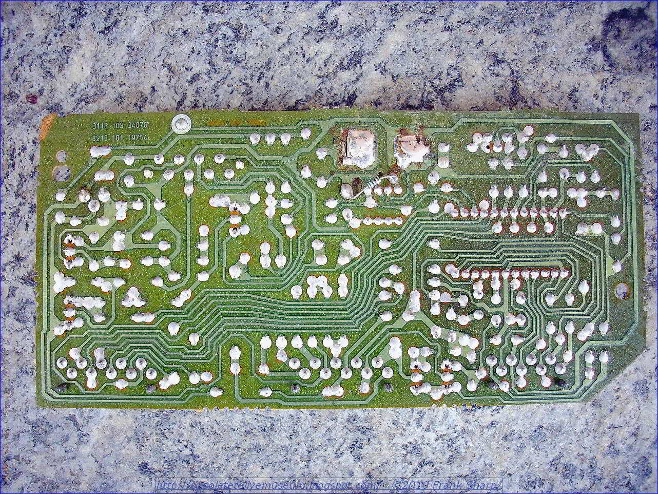
No comments:
Post a Comment
The most important thing to remember about the Comment Rules is this:
The determination of whether any comment is in compliance is at the sole discretion of this blog’s owner.
Comments on this blog may be blocked or deleted at any time.
Fair people are getting fair reply. Spam and useless crap and filthy comments / scrapers / observations goes all directly to My Private HELL without even appearing in public !!!
The fact that a comment is permitted in no way constitutes an endorsement of any view expressed, fact alleged, or link provided in that comment by the administrator of this site.
This means that there may be a delay between the submission and the eventual appearance of your comment.
Requiring blog comments to obey well-defined rules does not infringe on the free speech of commenters.
Resisting the tide of post-modernity may be difficult, but I will attempt it anyway.
Your choice.........Live or DIE.
That indeed is where your liberty lies.
Note: Only a member of this blog may post a comment.