


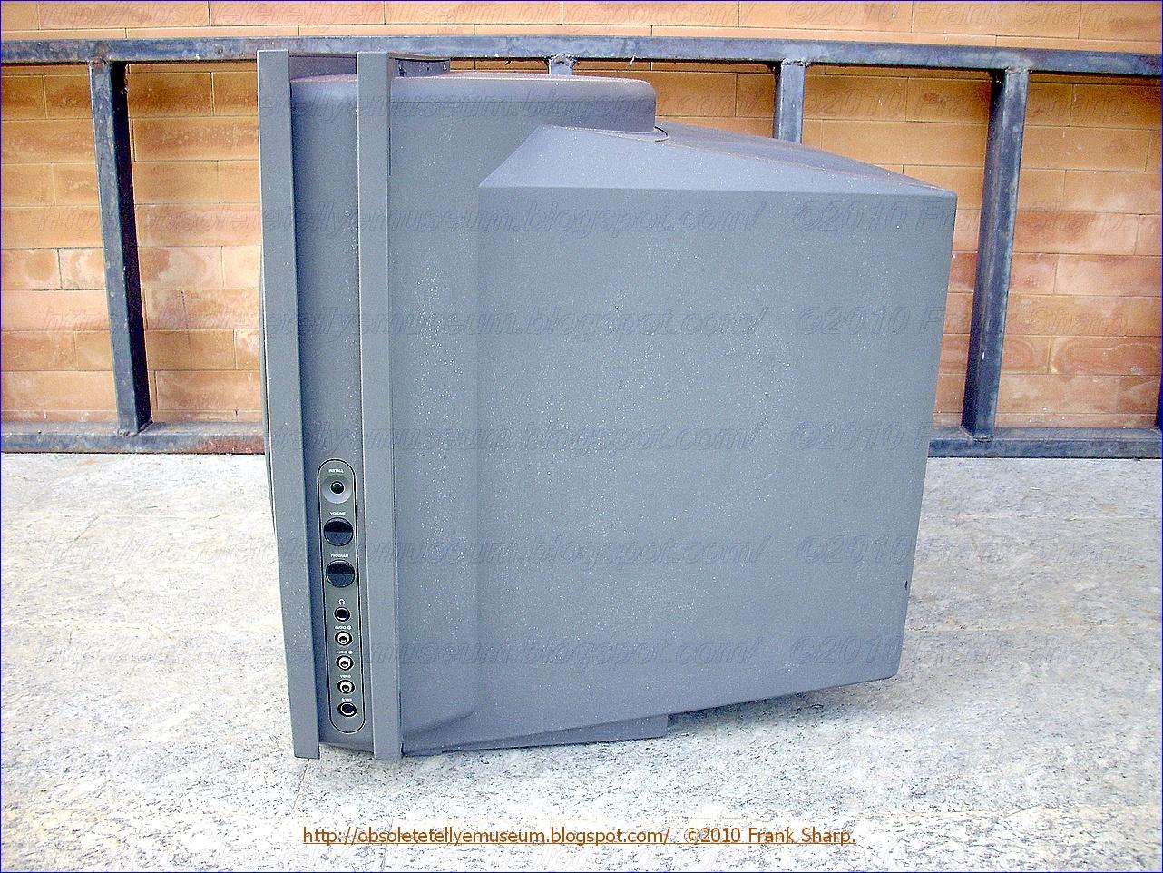


The PHILIPS 28PW9608 MATCHLINE IDTV 100HZ is a Digital 100Hz ScanRate television with 16/9 screen aspect ratio.
The PHILIPS 28PW9608 MATCHLINE IDTV 100Hz was first PHILIPS color television with a 16/9 screen combined with 2nd generation 100Hz scan rate technlogy entirely based on PHILIPS chipset semiconductors.
The television receiver has an alphanumeric display which appears on the picture tube screen, to give the user data on the tuned channel number, colour settings and other operating data. The digital processor which generates the characters for display also controls the channel setting, etc., under the control of a digital remote control unit . The processor has an associated memory circuit for permanent tuning back up. The control of the capacitance diode tuner is achieved by the processor altering the dividing factor of a feedback loop to a phase/frequency comparator . The other input to the comparator is a divided frequency from a quartz oscillator.
The PHILIPS 28PW9608 MATCHLINE IDTV 100HZ It's an IDTV an improved definition television (IDTV) set including a motion sensing circuit for sensing motion of images and generating a motion sensing signal, a motion adaptive Y/C separating circuit separating a composite video signal into a luminance signal and a chrominance signal on the basis of the motion sensing signal, chroma demodulation and matrix circuit generating three primary color signals of red, green, and blue from separate luminance and chrominance signals separated at the Y/C separating circuit, and a motion adaptive scanning line converting circuit for converting a line scanning method of the three primary color signals to a progressive line scanning, while effecting a field or line interpolation operation to the three primary color signals. The television set is characterized by a first selector for alternatively supplying external luminance and chrominance signals supplied from the outside or the separate luminance and chrominance signals to the chroma demodulation and matrix circuit, and a second selector for alternatively supplying, the external luminance signal or a summing signal of said external luminance and chrominance signals, or the composite video signal to the motion sensing circuit.
IDTV represents a television set adapted for receiving a video signal of the present television broadcast standard, and improving the quality of picture only on the set's side by a signal processing operation using a field memory or a frame memory. Such IDTV sets were being introduced in the market from 1989 from GRUNDIG but enhanced by PHILIPS in the here today shown model.
In the existing television system, a so-called interlaced scanning system is carried out. That is, one picture (frame) is transmitted by two vertical scannings (fields). This interlaced scanning system is considered in order to increase the number of scanning lines as much as possible in a limited frequency band without a flicker being perceived by a viewer.
However, in the CCIR system employed mainly in European countries, the field frequency is 50 Hz. By this frequency, the flicker can not be removed completely and the flicker becomes conspicuous particularly when the brightness of the television picture is high.
PHILIPS 28PW9608 MATCHLINE IDTV 100HZ TELEVISION In a known arrangement, the frame rate of a television signal is doubled by using a field store. In a first operating mode, each field of the television signal is entered into the field store in this arrangement and read out twice at twice the frequency. In a second mode, only every second field is entered into the field store and read out four times at twice the frequency. In an arrangement for converting an original picture signal representing a sequence of frames, each of which is composed of two interlaced fields, into a converted picture signal which has a double field frequency with respect to the original picture signal, is for doubling the field frequency, for the purpose of noise reduction, motion compensation and line flicker reduction.
The PHILIPS 28PW9608 MATCHLINE IDTV 100HZ was first PHILIPS 100Hz set featuring an Advanced Color Comb Filter. Chrominance and luminance information can be separated by appropriately combing the composite signal spectrum. Known combing arrangements take advantage of the fact that the odd multiple relationship between chrominance signal components andhalf the line scanning frequency causes the chrominance signal components for corresponding image areas on successive lines to be 180.degree. out of phase with each other. Luminance signal components for corresponding image areas on successive linesare substantially in phase with each other.
Furthermore it has stereo sound,
Multistandard capability.
PIP, Picure In Picture.
3 AV SCART SOCKETS.
AV connectivity RCA type.
SVHS CONNECTORS
4 External loudspeakers connectors
Teletext.
Tone control
OSD
PLL/TRD Tuning system fully Computerized.
Programs search first start Autostore.
On screen display (OSD) arrangements employed in video processing systems include a switching (or "multiplexing") network for switching between graphic image representative signals and normal video signals so that a graphic image can be displayed on the screen of a picture reproduction device either in place of the image represented by the video signals or together with (inserted in) the image. The graphic image can take the form of alphanumeric symbols or-pictorial graphics, and can be used to indicate status information, such as channel numbers or time, or operating instructions.
In an OSD arrangement for use in an analog video signal processing system, the multiplexing network typically operates to switch in levels corresponding to the desired intensity of respective portions of the graphic image at the time the graphic image portions are to be displayed. In such an arrangement the graphic image representative signals take the form of timing pulses which occur when the graphic image portions are to be displayed and are used to control the multiplexing network. Such an analog OSD arrangement can also be used in a digital video processing system, but requires that the video signals be first converted to analog form. While digital video signal processing systems typically include a digital-to-analog converter section in which the digital video signals are converted to analog form, it may be more cost effective for the OSD arrangement to be incorporated as an integral part of the digital video processing section.
Furthermore the PHILIPS 28PW9608 MATCHLINE IDTV 100HZ features Beam Scan Velocity modulation.It is well known that an improvement in apparent picture resolution can be achieved by modulating the beam scan velocity in accordance with the derivative of the video signal which controls the beam intensity. This video signal is referred to as the luminance signal and the derivative of the luminance signal is employed for such control. An advantage of this method over a peaking approach to picture sharpness enhancement is the avoidance of blooming of peaked white picture elements.
When the phosphor screen of a video signal reproducing apparatus, such as, the screen of the cathode ray tube in a television receiver, is scanned by an electron beam or beams so as to form a picture or image on the screen, the beam current varies with the luminance or brightness level of the input video signal. Therefore, each electron beam forms on the phosphor screen a beam spot whose size is larger at high brightness levels than at low brightness levels of the image so that sharpness of the reproduced picture is deteriorated, particularly at the demarcation between bright and dark portions or areas of the picture. Further, when a beam scanning the screen in the line-scanning direction moves across the demaraction or edge between dark and bright areas of the picture, for example, black and white areas, respectively, the frequency response of the receiver does not permit the beam intensity to change instantly from the low level characteristic of the black area to the high level characteristic of the white area. Therefore, the sharpness of the reproduced image is degraded at portions of the image where sudden changes in brightness occur in response to transient changes in the luminance or brightness of the video signal being reproduced. The increase in the beam current and in the beam spot size for bright portions of the reproduced picture or image and the inadequate frequency response of the television receiver to sudden changes in the brightness or luminance level of the incomming video signal are additive in respect to the degradation of the horizontal sharpness of the reproduced image or picture.
It is well known that an improvement in apparent picture resolution can be achieved by modulating the beam scan velocity in accordance with the derivative of the video signal which controls the beam intensity. This video signal is referred to as the luminance signal and the derivative of the luminance signal is employed for such control. An advantage of this method over a peaking approach to picture sharpness enhancement is the avoidance of blooming of peaked white picture elements.
It is known in the prior art to apply a differentiated video signal to the input of a double ended limiter incorporating a pair of threshold circuits. The limiter consists of two separate differential amplifiers, where each amplifier is separately biased to provide double ended limiting as well as to provide coring. The limiter arrangement develops a doubly clipped signal output which does not respond to excursions of the differentiated signal which lie below selected threshold magnitudes. Thus the gain of the limiter is such as to provide sharpness enhancement for slow transients while precluding excessive supplemental beam deflection with fast transients. The coring capability of the limiter arrangement significantly lessens the likelihood of noise visibility.
PHILIPS 28PW9608 MATCHLINE IDTV 100HZ IS A WIDE SCREEN TELEVISION The invention relates to the field of televisions, for example those televisions having a wide display format ratio screen, which must interpolate video data to implement various display formats. Most televisions today have a format display ratio, horizontal width to vertical height, of 4:3. A wide format display ratio corresponds more closely to the display format ratio of movies, for example 16:9. The invention is applicable to both direct view televisions and projection televisions. Televisions having a format display ratio of 4:3, often referred to as 4 X 3, are limited in the ways that single and multiple video signal sources can be displayed. Television signal transmissions of commercial broadcasters, except for experimental material, are broadcast with a 4 X 3 format display ratio. Many viewers find the 4 X 3 display format less pleasing than the wider format display ratio associated with the movies. Televisions with a wide format display ratio provide not only a more pleasing display, but are capable of displaying wide display format signal sources in a corresponding wide display format. Movies "look" like movies, not cropped or distorted versions thereof. The video source need not be cropped, either when converted from film to video, for example with a telecine device, or by processors in the television.
Televisions with a wide display format ratio are also suited to a wide variety of displays for both conventional and wide display format signals, as well as combinations thereof in multiple picture displays. However, the use of a wide display ratio screen entails numerous problems. Changing the display format ratios of multiple signal sources, developing consistent timing signals from asynchronous but simultaneously displayed sources, switching o between multiple sources to generate multiple picture displays, and providing high resolution pictures from compressed data signals are general categories of such problems. Such problems are solved in a wide screen television according to this invention. A wide screen television according to various inventive arrangements is capable of providing high resolution, single and multiple picture displays, fromsingle and multiple sources having similar or different format ratios, and with selectable display format ratios.
Televisions with a wide display format ratio can be implemented in television systems displaying video signals both at basic or standard horizontal scanning rates and multiples thereof, as well as by both interlaced and noninterlaced scanning. Standard NTSC video signals, for example, are displayed by interlacing the successive fields of each video frame, each field being generated by a raster scanning operation at a basic or standard horizontal scanning rate of approximately 15,734 Hz. The basic scanning rate for video signals is variously referred to as fπ, 1fH, and 1 H. The actual frequency of a 1fH signal will vary according to different video standards. In accordance with efforts to improve the picture quality of television apparatus, systems have been developed for i s displaying video signals progressively, in a noninterlaced fashion. Progressive scanning requires that each displayed frame must be scanned in the same time period allotted for scanning one of the two fields of the interlaced format. Flicker free AA-BB displays require that each field be scanned twice, consecutively. In each case, the horizontal scanning frequency must be twice that of the standard horizontal frequency. The scanning rate for such progressively scanned or flicker free displays is variously referred to as 2fπ and 2H. A 2fH scanning frequency according to standards in the United States, for example, is approximately 31 ,468 Hz.
A wide screen television according to the inventive arrangements taught herein has all of the capabilities and advantages described above.
- The PHILIPS 28PW9608 MATCHLINE IDTV 100HZ Features a multistandard PAL/SECAM/NTSC 3.58 & 4.43 CCIR B/G/H/I/L/D/K/M. The different coding processes, e.g. NTSC, PAL and SECAM, introduced into the known colour television standards, differ in the nature of the chrominance transmission and in particular the different systems make use of different colour subcarrier frequencies and different line frequencies.
The following explanations relate to the PAL and NTSC systems, but correspondingly apply to video signals of other standards and non-standardized signals.
The colour subcarrier frequency (fsc) of a PAL system and a NTSC system is fsc(NTSC) = 3.58 MHz or fsc(PAL) = 4.43 MHz.
In addition, in PAL and NTSC systems the relationships of the colour subcarrier frequency (fsc) to the line frequency (fh) are given by fsc(NTSC) = 227.50 * fh or 4•fsc(NTSC) = 910 • fh fsc(PAL) = 283.75 * fh or 4•fsc(PAL) = 1135 • fh so that the phase of the colour subcarrier in the case of NTSC is changed by 180°/line and in PAL by 270°/line.
The invention relates to a digital multistandard decoder for video signals and to a method for decoding video signals. Colour video signals, so-called composite video, blanking and sync signals (CVBS) (chroma-video-blanking-sync) signal is a signal comprising both the chrominance and the luminance component of the video signal. Therefore, the CVBS video signal may be PAL video signal, a SECAM video signal, or an NTSC video signal. are essentially composed of a brightness signal or luminance component (Y), two colour difference signals or chrominance components (U, V or I, Q), vertical and horizontal sync signals (VS, HS) and a blanking signal (BL).
In order to decode a video signal and restore a color image, a color TV set has to identify the color TV standard used at the emission. Conventional color TV sets are equipped with a system for automatically identifying the norm or standard of the color TV set used for the emission. The invention more particularly relates to an automatic method for identifying a color TV standard in a multistandard TV set.
Presently, the most commonly used color TV standards are PAL, NTSC and SECAM standards. For these three standards, each line of the composite video signal comprises a synchronization pulse, a burst of a few oscillations of the chrominance sub-carrier signal, then the signal itself corresponding to the image, comprising superimposed luminance and chrominance information, the latter information being carried by the luminance signal.
The characteristics of the chrominance sub-carrier in the various PAL, NTSC and SECAM standards are defined in the published documents concerning these standards and will not be described in detail here. However, the main characteristics of these various standards will be briefly reminded because these indications are useful for a better understanding of the invention.
In the PAL standard, the frequency of the chrominance sub-carrier is equal for all the lines, but the phase of one of the modulation vectors varies + or -90° from one line to another. The frequency of the chrominance sub-carrier is standardized at 4.43 Mhz. In this system, the burst signal is also shifted by + or -90° from one line to the next.
In the NTSC standard, the chrominance sub-carrier is equal for all the lines.
In the SECAM standard, one uses two chrominance sub-carrier frequencies which alternate from one line to another, at 4.25 Mhz and 4.40 Mhz, respectively. These two chrominance sub-carriers are frequency modulated.
The multistandard color TV sets must have distinct internal systems designed to decode the luminance and chrominance signals for each standard used.
Therefore, these TV sets have to previously identify the received standard.
Systems for automatically identifying the standard used already exist. Generally, for such an automatic standard identification, the systems known use the bursts of the chrominance sub-carrier signal that are present at the beginning of each line. In fact, these bursts are standardized and calibrated samples of the chrominance sub-carrier transmitted on the video signal and comprise all the characteristic information concerning the transmitted color standard. The information contained in these bursts represents the frequency, the phase of one of the modulation vectors and the frequency or phase variation of one line with repect to the next one.
- CTI Picture Improvements circuitry in which colour signal, e.g. the line-sequential colour difference signals (R-Y,B-Y), is processed by an edge steepening circuit e.g. a colour transient improver and/or a two-line delay line in which the colour signals from two lines are added. The delay line may be part of a drop-out compensation circuit in which the colour signal of line n is replaced by the signal present for line n-2. A CCD-line may be used as the two-line delay line, and an amplitude limiter included. ADVANTAGE - Increased picture sharpness and improved signal-to-noise ratio.
The Tv set here shown features a PIP picture-in-picture (PIP or pix-in-pix) feature; in a digital television system having a picture-in-picture (PIP or pix-in-pix) feature, two images from possibly unrelated sources are displayed simultaneously on the TV screen as a single composite image. The composite image includes a small picture (defined by an auxiliary video signal, for example, from a VCR) displayed as an inset within a large main picture (defined by a primary video signal, for example, from the TV antenna). The output signal of one tuner or of other TV signal sources in the base band are digitized and stored in a part of a memory. After automatic switching over to another TV-channel, this new signal is stored in another part of the memory and so on. The whole memory is then read out continuously and produces the displayed multipicture on the screen.
More specifically, the present invention pertains to a television receiver with a multipicture display.
In a television receiver with multipicture display a single video signal can be reproduced simultaneously in two or more subareas, or two or more different video signals can each be reproduced in associated subareas. Each of the subareas can display either a reduced-size picture or a part of the picture supplied by a video-signal source. A digital signal-processing circuit converts the signals from the video-signal source to picture data consisting of luminance and color data for each picture element. A random-access memory (RAM) holds the picture data of the entire screen. A control unit controls the writing of the picture data into an area of the RAM depending on the number of video signals to be reproduced and the line-by-line readout, with only selected lines being transferred from the video-signal source into the associated memory area. A digital-to-analg converted which is furnished with the picture data read from the RAM delivers the analog red, green, and blue signals.
A television receiver of this kind is described in a printed publication by Intermetall Semiconductors ITT, "VMC Video Memory Controller", August 1985.
That television receiver circuit uses random-access memories (RAMs). For the multipicture display, the screen is divided into up to nine equal-sized subareas which each contain a part of a picture of normal size or a complete picture of reduced size. In that mode, successively produced "snapshots" of up to nine different video signals can be displayed simultaneously. The switching of the video signals takes place manually.
Offenlegungsschrift DE No. 24 13 839 A1 describes a circuit for a television receiver with a facility for simultaneously reproducing two or more programs. In a part of the picture of the directly received main program, the secondary program, received with a single switchable tuner, is stored in a memory with a reduced number of lines and is called up line by line when the electron beam of the picture tube sweeps across the predetermined part of the picture. The disadvantage of this method lies in horizontal grating-like interference in the main picture which results from the fact that lines of the main picture are missing at regular intervals when the tuner has been switched to the secondary program, and which can only be incompletely compensated.
Accordingly, the problem to be solved by the invention is to provide a circuit of the above kind with which the grating-like interference caused during reproduction using the above-described single-tuner switching method is eliminated.
The output signal of one tuner or of other TV signal sources in the base band are digitize and stored in part of a memory. After automatic switching over to another TV-channel, this new signal is stored in another part of the memory and so on.
The whole memory is then read out continuously and produces the multi-picture display on the screen. Another advantage consists in the fact that, for the construction of the whole screen picture, all picture data are withdrawn from the RAM, so that the usual picture-improvement techniques can be applied. By fast readout from the memory rows, the displayed picture is freed from both line flicker and background flicker.
By changing the sampling rates of the different video-signal sources, it is readily possible to monitor the latter, nearly up to the still picture. In an arrangement in accordance with the invention digital picture processing and digital storage are used thereby permitting the circuit to process analog or digital signals,from video signal sources.
The PHILIPS 28PW9608 MATCHLINE IDTV 100HZ has his own design type and was a very expensive top model ,they aren't much sold so they're slightly rare.
About Screen Formats...............
It is difficult to know exactly what to make of the unfolding widescreen TV saga, which seems to be yet another example of failure to agree to a TV standard. Is it perhaps simply an attempt by the European TV industry to snatch a temporary advantage over Far Eastern manufacturers?
Certainly it's the European tubemakers that have developed the technology.
But if this is the case the question that has to be asked is whether widescreen TV is a further example of an attempt by technology rather than consumer demand to drive the market forwards? If so it could well be a mistake. People won't buy technology for the sake of it: they'll buy only what suits them.
The 16:9 aspect ratio sets that have been announced so far are a mixed batch. Nokia has opted for 625 -line PAL, Thomson has opted for 1,250 -line PAL while Philips has decided on 625 -line PAL with a 100Hz field rate. Nokia feels that the wide screen is the important thing rather than any change to basic TV standards. The company points to the cost advantage of using a standard chassis to drive the new type of tube. But evenhere the wide screen presentation is seen as essentially a top of the range phenomenon. In this case why not go the whole hog? With a chassis that features digital signal processing, why not take advantage of the opportunity to improve the definition and get rid of flicker once and for all? There are arguments as to exactly how much better a picture you get for your money at higher timebase frequencies.
What this seems to boil down to is that compromises, as always with TV, have to be accepted. The argument is over what compromise to accept. It's a rather pointless argument really and one can't help but feel that the motivation behind it is simply a matter of gaining marketing clout rather than achieving the best in good picture reproduction.
There is much to be said for the view that a well set up display using conventional technology and a decent aerial system, with no corner cutting in circuit design, will with the presently available transmissionsprovide as good a picture as any for the viewer rather than the technology buff.
Representatives of the main Japanese manufacturers in the UK have been making disparaging comments about widescreen TV. The case was put forcibly by Mark Todd, Toshiba's marketing director. He hit the headlines with coments that widescreen TV was "premature" and "a joke", but rather more to the point he suggested that instead of buying a set that is "too big" and "too expensive" the consumer would be better off with a 34in. Nicam set featuring surround sound.
The money saved could, he added, be invested in a building society. The debate has been clouded by dispute over what programming is available. At present it seems to be limited to a few tapes and Continental satellite channels transmitted in D2-MAC form. Not much really to justify lashing out on a set that costs a few thousand pounds. Since some rather rude remarks about the 16:9 picture format have been somewhat severely taken to task over what is and what isn't a natural display based on the characteristics of human vision, in particular who quoted a considerable amount of research.
The fact that human eyes are horizontally displaced, giving perception somewhat elongated in the horizontal plane compared to the vertical plane, looks a clincher.
But this rather overlooks the reason for us having two eyes in the first place to achieve bifocalvision. The images from the two eyes are superimposed to give us a three-dimensional fieldof view. It's nothing to do with aspect ratio!
The aspect ratio debate continues in actual times with minor noise and debate is been gratified by some support amongst more recent observations from people.
It all arrived too late for this issue, but watch this space as they say. What does rather intrigue me in all this is whether sight is really a scientific matter. It is, of course, as a subject for study. But as an aspect of natural history it seems more akin to disciplines such as economics rather than pure science.
Those who take an interest in the endless economic debate, with one plausible argument after another seeming to establish opposite points of view, will appreciate this. The problem of course is that you can't conduct conclusive experiments with the subject matter of economics. You can't say right, call a halt, go back five years and see what happens if we alter the conditions. Anything of an historical nature can only be observed and, in a more or less helpful manner, explained. That seems to be the case with human perception. You can't experiment with different vision systems. You have to understand as best you can the one we've ended up with. However that may be, the TV industry is not doing itself any great favours with its continual change.
To the 4:3 and 16:9 aspect ratios we now have a proposed compromise 14:9. It's not easy of course to arrive at decisions with absolute certainty. Technological evolution continuously and often suddenly shifts, and new possibilities have a habit of coming at times that are inconvenient for the standards decision makers. Perhaps we should give up worrying about TV standards and accept the fact that there have always been and always will be different ways of going about things, with various advantages and disadvantages. Let's just sit back and watch the thing unfold. It would be nice to take a relaxed view like that. But of course there's more at stake.
Sets have to be manufactured to standards, broadcasters have to observe system parameters and, at ourend of things, the public has to be presented with a good case for buying what's available. It doesn'thelp the salesman to have to work in an atmosphere of continuing uncertainty.
One more comment about digital in 2000..............
Over the years we have learnt that one of the most important things in video/ TV technology is selecting the best system to use. We have also seen how difficult this can be. Prior to the start of the colour TV era in Europe there was an great to-do about the best system to adopt. The US NTSC system seemed an obvious choice to start with. It had been proved in use, and refine- ments had been devised. But alternative, better solutions were proposed - PAL and Secam. PAL proved to be a great success, in fact a good choice.The French Secam system seems to have worked just as well. Apart from the video tape battles of the Seventies, the next really big debate concerned digital TV. When it came to digital terrestrial TV (DTT), Europe and the USA again adopted different standards.One major difference is the modulation system used for transmission. Coded orthogonal frequency division multiplexing (COFDM) was selected for the European DVB system, while in the USA a system called 8VSB was adopted. COFDM uses quadrature amplitude modulation of a number of orthogonal carriers that are spread across the channel bandwidth. Because of their number, each carrier has a relatively low bit rate.The main advantage of the system is its excellent behaviour under multipath reception conditions. 8VSB represents a rather older, pre phase modulation technoogy: eight state amplitude modulation of a single carrier, with a vestigial sideband. The decision on the US system was assigned to the Advanced Television Systems Committee (ATSC), reporting to the FCC. The system it proposed was approved by the FCC on December 26th, 1996. The curious date might suggest that there had been a certain amount of politicking. In fact there had been an almighty row between the TV and computer industries about the video standard to adopt, the two fearing that one or other would gain an advantage as the technologies converged. It was 'resolved' by adopting a sort of "open standard" we are talking about resolution and scanning standards here - the idea apparently being that the technology would somehow sort itself out.There seems to have been rather less concern about the modulation standard. 8VSB was adopted because it was assumed to be able to provide a larger service area than the alternatives, including COFDM, for a given transmitter power. Well, the USA is a very large place! But the US TV industry, or at least some parts of it, is now having second thoughts. Once the FCC had made its decision, there was pressure to get on with digital TV. In early 1998 there were announce- ments about the start of transmissions and broadcasters assured the FCC that DTT would be available in the ten areas of greatest population concentration by May 1999. Rapid advances were expected, with an anticipated analogue TV switch -off in 2006. So far however things have not gone like that. At the end of 1999 some seventy DTI' transmitters were in operation, but Consumer Electronics Manufacturers Association estimates suggest that only some 50,000 sets and 5,000 STBs had been sold.There have been many reports of technical problems, in particular with reception in urban and hilly areas and the use of indoor aerials, also with video/audio sync and other matters. Poor reception with indoor aerials in urban conditions is of particular concern: that's how much of the population receives its TV. The UK was the first European country to start DTI', in late 1998 - at much the same time as in the USA. The contrast is striking. ONdigital had signed up well over 500,000 subscribers by the end of 1999, a much higher proportion of viewers than in the USA. Free STBs have played a part of course, but it's notable that DTT 's reception in the UK has been relatively hassle -free. In making this comparison it should also be remembered that the main aim of DTT technology differs in Europe and the USA.The main concern in Europe has been to provide additional channels. In the USA it has been to move to HDTV, in particular to provide a successor the NTSC system. There have been plenty of channels in the USA for many a year. For example the DirecTV satellite service started in mid 1994 and offers some 200 channels. Internationally, various countries have been comparing the US and European digital systems. They have overwhelmingly come down in favour of the DVB system. There have been some very damaging assessments of the ATSC standard. The present concern in the US TV industry results from this poor domestic take up and lack of international success. Did the FCC make a boob, in particular in the choice of 8VSB? Following compara- tive tests carried out by Sinclair Broadcasting Group Inc., the company has petitioned the FCC to adopt COFDM as an option in the ATSC standard. Not only did its tests confirm poor reception with indoor aerials: they also established that the greater coverage predicted for 8VSB failed to materialise in practice. Could the USA have two DTT transmission standards? It seems unlikely. It would involve dual standard receivers and non standardisation of transmitters. In the all important business of system selection, it looks as if the FCC got it wrong.
.................................... It is obviously wasteful to duplicate terrestrial TV transmissions in analogue and digital form. Sooner or later transmissions will all be digital, since this is a more efficient use of spectrum space. The question is when? It would suit some to switch off the analogue transmitters as soon as possible. 2006 has been suggested as a time to start, with ana- logue transmissions finally ending in 2010. All very neat and tidy. Whether it will work out in that way is another matter. Strong doubts are already beginning to be aired.
The government has, quite properly, laid down conditions to be met before the switch off occurs. Basically that the digital signal coverage should equal that achieved for analogue TV, currently 99.4 per cent of the population, and that digital receiving equipment should be available at an affordable price. The real problem is that there is a difference between a coverage of 99.4 per cent and 99.4 per cent of the population actually having digital receiving equipment. Why should those who are interested in only free - to -air channels go out and buy/rent a digital receiver? It is already becoming evident that this represents a fair chunk of the population.
The ITC has warned the government that the 2006-2010 timetable is in jeopardy. Peter Rogers, the ITC's chief executive, has said "we need to persuade people only interested in watching free -to -air television to switch to digital. "Unless we do, there will be no switch - over." Well not quite, because the analogue receivers will eventually wear out and have to be replaced. But that could take a long, long time. Meanwhile many people will expect to be able to continue to watch their usual TV fare using their existing analogue receivers.Research carried out by Culture Secretary Chris Smith's department has established that between forty and fifty per cent of the population expects the BBC licence to cover their TV viewing, which means what they get at present in analogue form. A substantial percentage of the population simply isn't interested in going digital. In fact take up of integrated receiver -decoders, as opposed to the free digital set -top boxes, has so far been very slow.Of five million TV sets sold in the UK year 1999 , only 10,000 were digital. There are important factors apart from overall coverage and how many people have sets. There is the extension of coverage, which becomes more difficult to achieve eco- nomically as the number of those not covered decreases. There is the problem of reception quality. And there is the question of domestic arrangements and convenience. Extending coverage to the last ten fifteen per cent of the population by means of conventional terrestrial transmitters will be expensive. Mr Smith's department seems to have conceded that other methods of signal delivery may have to be adopted - by satellite, by microwave links or by cable. The latter has of course never been economic where few households are involved.The frequency planners have been trying to find ways of increasing coverage even to well populated areas. There are so many areas where problems of one sort or another make the provision of DTT difficult. Satellite TV is the obvious solution.The time may well come when it is wondered why anyone bothered with DTT. Signal quality is becoming an increasingly important factor as the digital roll out continues. In areas where the signal is marginal, viewers could experience the extreme irritation of picture break up or complete loss like even todays. This is quite apart from the actual quality of the channel, which depends on the number of bits per second used. There is a maximum number of bits per multiplex, the total being shared by several channels. The fewer the bits, the poorer the picture in terms of definition and rendering.There have already been complaints about poor quality. The question of domestic arrangements is one that has not so far received adequate public attention. Most households 2000 nowadays don't have just one TV set that the family watches. They have a main one, probably, almost certainly one or more VCRs, and several other sets around the house to serve various purposes. What 'the percentage of households that have digital TV' should really mean is the percentage willing to replace all this equipment. It will be expensive, and people would not be happy if they were told to throw away their other equipment when they get a single nice new all singing all dancing widescreen digital TV set. It fact there would be uproar. The move from analogue to digital is not like that from 405 to 625 lines, which went fairly smoothly.
In those days few people had video equipment or a multitude of sets. The transition to digital is not going to be smooth, and the suggestion of a switch off during 2006-2010 already looks totally unrealistic. Unless the government subsidises or gives away digital TV sets - and why should it? - people will expect their existing equipment to continue to be usable.So it's likely that analogue TV will be with us for many years yet. But that would be the end of analogue too..............................Indeed...............................
----------------------------------------------------------------------------

Koninklijke Philips Electronics N.V. (Royal Philips Electronics Inc.), most commonly known as Philips, (Euronext: PHIA, NYSE: PHG) is a multinational Dutch electronics corporation.
Philips is one of the largest electronics companies in the world. In 2009, its sales were €23.18 billion. The company employs 115,924 people in more than 60 countries.
Philips is organized in a number of sectors: Philips Consumer Lifestyles (formerly Philips Consumer Electronics and Philips Domestic Appliances and Personal Care), Philips Lighting and Philips Healthcare (formerly Philips Medical Systems).
he company was founded in 1891 by Gerard Philips, a maternal cousin of Karl Marx, in Eindhoven, Netherlands. Its first products were light bulbs and other electro-technical equipment. Its first factory survives as a museum devoted to light sculpture. In the 1920s, the company started to manufacture other products, such as vacuum tubes (also known worldwide as 'valves'), In 1927 they acquired the British electronic valve manufacturers Mullard and in 1932 the German tube manufacturer Valvo, both of which became subsidiaries. In 1939 they introduced their electric razor, the Philishave (marketed in the USA using the Norelco brand name).
Philips was also instrumental in the revival of the Stirling engine.
As a chip maker, Philips Semiconductors was among the Worldwide Top 20 Semiconductor Sales Leaders.
In December 2005 Philips announced its intention to make the Semiconductor Division into a separate legal entity. This process of "disentanglement" was completed on 1 October 2006.
 On
2 August 2006, Philips completed an agreement to sell a controlling
80.1% stake in Philips Semiconductors to a consortium of private equity
investors consisting of Kohlberg Kravis Roberts & Co. (KKR),
Silver Lake Partners and AlpInvest Partners. The sale completed a
process, which began December 2005, with its decision to create a
separate legal entity for Semiconductors and to pursue all strategic
options. Six weeks before, ahead of its online dialogue, through a
letter to 8,000 of Philips managers, it was announced that they were
speeding up the transformation of Semiconductors into a stand-alone
entity with majority ownership by a third party. It was stated then
that "this is much more than just a transaction: it is probably the
most significant milestone on a long journey of change for Philips and
the beginning of a new chapter for everyone – especially those
involved with Semiconductors".
On
2 August 2006, Philips completed an agreement to sell a controlling
80.1% stake in Philips Semiconductors to a consortium of private equity
investors consisting of Kohlberg Kravis Roberts & Co. (KKR),
Silver Lake Partners and AlpInvest Partners. The sale completed a
process, which began December 2005, with its decision to create a
separate legal entity for Semiconductors and to pursue all strategic
options. Six weeks before, ahead of its online dialogue, through a
letter to 8,000 of Philips managers, it was announced that they were
speeding up the transformation of Semiconductors into a stand-alone
entity with majority ownership by a third party. It was stated then
that "this is much more than just a transaction: it is probably the
most significant milestone on a long journey of change for Philips and
the beginning of a new chapter for everyone – especially those
involved with Semiconductors".In its more than 115 year history, this counts as a big step that is definitely changing the profile of the company. Philips was one of few companies that successfully made the transition from the electrical world of the 19th century into the electronic age, starting its semiconductor activity in 1953 and building it into a global top 10 player in its industry. As such, Semiconductors was at the heart of many innovations in Philips over the past 50 years.

On 21 August 2006, Bain Capital and Apax Partners announced that they had signed definitive commitments to join the expanded consortium headed by KKR that is to acquire the controlling stake in the Semiconductors Division.
On 1 September 2006, it was announced in Berlin that the name of the new semiconductor company founded by Philips is NXP Semiconductors.
Coinciding with the sale of the Semiconductor Division, Philips also announced that they would drop the word 'Electronics' from the company name, thus becoming simply Koninklijke Philips N.V. (Royal Philips N.V.).
PHILIPS FOUNDATION:
 The
foundations of Philips were laid in 1891 when Anton and Gerard Philips
established Philips & Co. in Eindhoven, the Netherlands. The
company begun manufacturing carbon-filament lamps and by the turn of
the century, had become one of the largest producers in Europe.
Stimulated by the industrial revolution in Europe, Philips’ first
research laboratory started introducing its first innovations in the
x-ray and radio technology. Over the years, the list of inventions has
only been growing to include many breakthroughs that have continued to
enrich people’s everyday lives.
The
foundations of Philips were laid in 1891 when Anton and Gerard Philips
established Philips & Co. in Eindhoven, the Netherlands. The
company begun manufacturing carbon-filament lamps and by the turn of
the century, had become one of the largest producers in Europe.
Stimulated by the industrial revolution in Europe, Philips’ first
research laboratory started introducing its first innovations in the
x-ray and radio technology. Over the years, the list of inventions has
only been growing to include many breakthroughs that have continued to
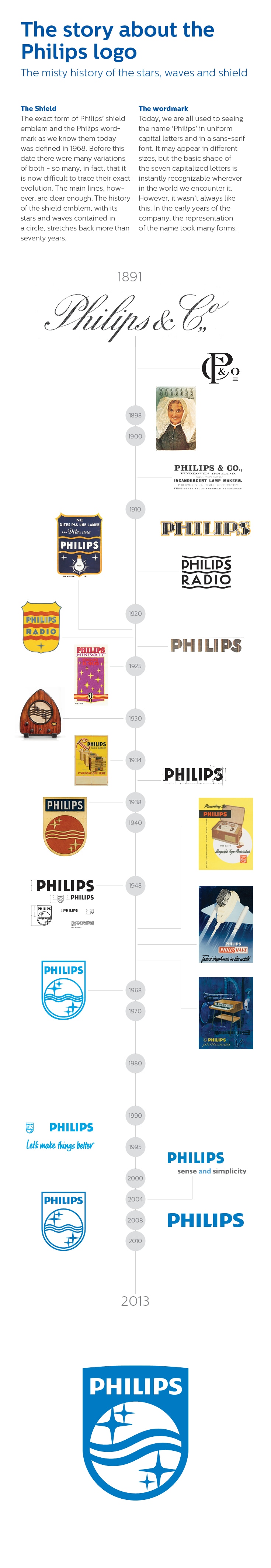
enrich people’s everyday lives.In the early years of Philips &; Co., the representation of the company name took many forms: one was an emblem formed by the initial letters of Philips ; Co., and another was the word Philips printed on the glass of metal filament lamps.
One of the very first campaigns was launched in 1898 when Anton Philips used a range of postcards showing the Dutch national costumes as marketing tools. Each letter of the word Philips was printed in a row of light bulbs as at the top of every card. In the late 1920s, the Philips name began to take on the form that we recognize today.
The now familiar Philips waves and stars first appeared in 1926 on the packaging of miniwatt radio valves, as well as on the Philigraph, an early sound recording device. The waves symbolized radio waves, while the stars represented the ether of the evening sky through which the radio waves would travel.
In 1930 it was the first time that the four stars flanking the three waves were placed together in a circle. After that, the stars and waves started appearing on radios and gramophones, featuring this circle as part of their design. Gradually the use of the circle emblem was then extended to advertising materials and other products.
At
this time Philips’ business activities were expanding rapidly and the
company wanted to find a trademark that would uniquely represent
Philips, but one that would also avoid legal problems with the owners of
other well-known circular emblems. This wish resulted in the
combination of the Philips circle and the wordmark within the shield
emblem.In 1938, the Philips shield made its first appearance. Although modified over the years, the basic design has remained constant ever since and, together with the wordmark, gives Philips the distinctive identity that is still embraced today.
The first steps of CRT production by Philips started in the thirties with the Deutsche Philips Electro-Spezial gesellschaft in Germany and the Philips NatLab (Physics laboratory) in Holland. After the introduction of television in Europe, just after WWII there was a growing demand of television sets and oscilloscope equipment. Philips in Holland was ambitious and started experimental television in 1948. Philips wanted to be the biggest on this market. From 1948 there was a small Philips production of television and oscilloscope tubes in the town of Eindhoven which soon developed in mass production. In 1976 a part of the Philips CRT production went to the town of Heerlen and produced its 500.000'th tube in 1986. In 1994 the company in Heerlen changed from Philips into CRT-Heerlen B.V. specialized in the production of small monochrome CRT's for the professional market and reached 1.000.000 produced tubes in 1996. In this stage the company was able to produce very complicated tubes like storage CRT's.
In 2001 the company merged into Professional Display Systems, PDS worked on LCD and Plasma technology but went bankrupt in 2009. The employees managed a start through as Cathode Ray Technology which now in 2012 has to close it's doors due to the lack of sales in a stressed market. Their main production was small CRT's for oscilloscope, radar and large medical use (X-ray displays). New experimental developments were small Electron Microscopy, 3D-TV displays, X-Ray purposes and Cathode Ray Lithography for wafer production. Unfortunately the time gap to develop these new products was too big.
28 of September 2012, Cathode Ray Technology (the Netherlands), the last Cathode Ray Tube factory in Europe closed. Ironically the company never experienced so much publicity as now, all of the media brought the news in Holland about the closure. In fact this means the end of mass production 115 years after Ferdinand Braun his invention. The rapid introduction and acceptation of LCD and Plasma displays was responsible for a drastic decrease in sales. Despite the replacement market for the next couple of years in the industrial, medical and avionics sector.
The numbers are small and the last few CRT producers worldwide are in heavy competition.
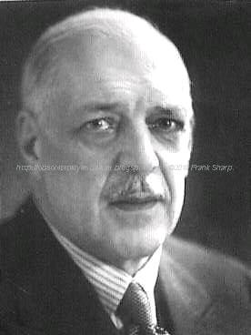
Gerard Philips:
 Gerard
Leonard Frederik Philips (October 9, 1858, in Zaltbommel – January 27,
1942, in The Hague, Netherlands) was a Dutch industrialist, co-founder
(with his father Frederik Philips) of the Philips Company as a family
business in 1891. Gerard and his younger brother Anton Philips changed
the business to a corporation by founding in 1912 the NV Philips'
Gloeilampenfabrieken. As the first CEO of the Philips corporation,
Gerard laid with Anton the base for the later Philips multinational.
Gerard
Leonard Frederik Philips (October 9, 1858, in Zaltbommel – January 27,
1942, in The Hague, Netherlands) was a Dutch industrialist, co-founder
(with his father Frederik Philips) of the Philips Company as a family
business in 1891. Gerard and his younger brother Anton Philips changed
the business to a corporation by founding in 1912 the NV Philips'
Gloeilampenfabrieken. As the first CEO of the Philips corporation,
Gerard laid with Anton the base for the later Philips multinational.Early life and education
Gerard was the first son of Benjamin Frederik David Philips (1 December 1830 – 12 June 1900) and Maria Heyligers (1836 – 1921). His father was active in the tobacco business and a banker at Zaltbommel in the Netherlands; he was a first cousin of Karl Marx.
Career
Gerard Philips became interested in electronics and engineering. Frederik was the financier for Gerard's purchase of the old factory building in Eindhoven where he established the first factory in 1891. They operated the Philips Company as a family business for more than a decade.
Marriage and family
On March 19, 1896 Philips married Johanna van der Willigen (30 September 1862 – 1942). They had no children.
Gerard was an uncle of Frits Philips, whom he and his brother brought into the business. Later they brought in his brother's grandson, Franz Otten.
Gerard and his brother Anton supported education and social programs in Eindhoven, including the Philips Sport Vereniging (Philips Sports Association), which they founded. From it the professional football (soccer) department developed into the independent Philips Sport Vereniging N.V.
Anton Philips:
 Anton
Frederik Philips (March 14, 1874, Zaltbommel, Gelderland – October 7,
1951, Eindhoven) co-founded Royal Philips Electronics N.V. in 1912 with
his older brother Gerard Philips in Eindhoven, the Netherlands. He
served as CEO of the company from 1922 to 1939.
Anton
Frederik Philips (March 14, 1874, Zaltbommel, Gelderland – October 7,
1951, Eindhoven) co-founded Royal Philips Electronics N.V. in 1912 with
his older brother Gerard Philips in Eindhoven, the Netherlands. He
served as CEO of the company from 1922 to 1939.Early life and education
Anton was born to Maria Heyligers (1836 – 1921) and Benjamin Frederik David Philips (December 1, 1830 – June 12, 1900). His father was active in the tobacco business and a banker at Zaltbommel in the Netherlands. (He was a first cousin to Karl Marx.) Anton's brother Gerard was 16 years older.
Career
In May 1891 the father Frederik was the financier and, with his son Gerard Philips, co-founder of the Philips Company as a family business. In 1912 Anton joined the firm, which they named Royal Philips Electronics N.V.
During World War I, Anton Philips managed to increase sales by taking advantage of a boycott of German goods in several countries. He provided the markets with alternative products.
Anton
(and his brother Gerard) are remembered as being civic-minded. In
Eindhoven they supported education and social programs and facilities,
such as the soccer department of the Philips Sports Association as the
best-known example.Anton Philips brought his son Frits Philips and grandson Franz Otten into the company in their times. Anton took the young Franz Otten with him and other family members to escape the Netherlands just before the Nazi Occupation during World War II; they went to the United States. They returned after the war.
His son Frits Philips chose to stay and manage the company during the occupation; he survived several months at the concentration camp of Vught after his workers went on strike. He saved the lives of 382 Jews by claiming them as indispensable to his factory, and thus helped them evade Nazi roundups and deportation to concentration camps.
Philips died in Eindhoven in 1951.
Marriage and family
Philips married Anne Henriëtte Elisabeth Maria de Jongh (Amersfoort, May 30, 1878 – Eindhoven, March 7, 1970). They had the following children:
* Anna Elisabeth Cornelia Philips (June 19, 1899 – ?), married in 1925 to Pieter Franciscus Sylvester Otten (1895 – 1969), and had:
o Diek Otten
o Franz Otten (b. c. 1928 - d. 1967), manager in the Dutch electronics company Philips
* Frederik Jacques Philips (1905-2005)
* Henriëtte Anna Philips (Eindhoven, October 26, 1906 – ?), married firstly to A. Knappert (d. 1932), without issue; married secondly to G. Jonkheer Sandberg (d. September 5, 1935), without issue; and married thirdly in New York City, New York, on September 29, 1938 to Jonkheer Gerrit van Riemsdijk (Aerdenhout, January 10, 1911 – Eindhoven, November 8, 2005). They had the following children:
o ..., Jonkheerin Gerrit van Riemsdijk (b. Waalre, October 2, 1939), married at Waalre on February 17, 1968 to Johannes Jasper Tuijt (b. Atjeh, Koeta Radja, March 10, 1930), son of Jacobus Tuijt and wife Hedwig Jager, without issue
o ..., Jonkheerin Gerrit van Riemsdijk (b. Waalre, September 4, 1948), married at Waalre, October 28, 1972 to Elie Johan François van Dissel (b. Eindhoven, October 9, 1948), son of Willem Pieter
Jacob van Dissel and wife Francisca Frederike Marie Wirtz, without issue.
(To see the Internal Chassis Just click on Older Post Button on bottom page, that's simple !)
A comment...........of a 1996 reality ..................
Philips, which seems to be a perennial walking wounded case. The company had appeared to be on the mend after a worldwide cost- cutting programme which was started five years ago when Jan Timmer took over as chairman.
But, following a sharp profits fall, with the company's first quarterly loss since 1992, a further shake up is being undertaken.
The difficulty is that the company operates in a mature market, in which prices are falling at an annual rate of six per cent. Manufacturers are competing by cutting costs to gain a larger share of static demand. It's not a situation in which any firm that does its own manufacturi
This is an approach that was pioneered many years ago by major Japanese manufacturers. Rather than make everything yourself, you rely on subcontractors who, in return, rely on you for their main source of work. It is hardly a cosy arrangement: the whole point seems to be that the major fain can exert pressure on its subcontractors, thereby - in theory - achieving optimum efficiency and cost-effectiveness. What happens when lower and lower prices are demanded for subcontracted work is not made clear.
 The whole edifice could collapse.
However that might be, this is the course on which Philips has now
embarked. The company is also to carry out distribution, sales and
marketing on a regional rather than a national basis, and has said that
it will not support Grundig's losses after this year.
The whole edifice could collapse.
However that might be, this is the course on which Philips has now
embarked. The company is also to carry out distribution, sales and
marketing on a regional rather than a national basis, and has said that
it will not support Grundig's losses after this year.But Philips' chief financial officer Dudley Eustace has said that it has "no intention of abandoning the television and audio business". One has to assume that the subcontracting will also be done on an international basis, as major Japanese firms have had to do. There is a sense of déjà vu about this, though one wishes Philips well - it is still one of the major contributors to research and development in our industry.
Toshiba, which has also just appointed a new top man, Taizo Nishimoro, provides an interesting contrast. Mr Nishimoro thinks that the western emphasis on sales and marketing rather than engineering is the way to go. So the whole industry seems to be moving full circle. Taizo Nishimoro has become the first non engineering president of Toshiba. Where the company cannot compete effectively on its own, he intends to seek international alliances or go for closures. He put it as follows. "The technology and the businesses we are engaged in are getting more complex.
 In
these circumstances, if we try to do everything ourselves we are making
a mistake." Here's how Minoru Makihara, who became head of Mitsubishi
Corporation four years ago, sees it. "Technologies are now moving so fast that it is impossible for the top manager to know all the details.
In
these circumstances, if we try to do everything ourselves we are making
a mistake." Here's how Minoru Makihara, who became head of Mitsubishi
Corporation four years ago, sees it. "Technologies are now moving so fast that it is impossible for the top manager to know all the details. Companies are now looking for generalists who can understand broad changes, delegate and provide leadership." Corporate change indeed amongst our oriental colleagues. Major firms the world over are facing similar problems and having to adopt similar policies.
In a mature market such as consumer electronics, you have to rely on marketing to squeeze the last little bit of advantage from such developments as Dolby sound and other added value features. The consumer electronics industry has been hoping that the digital video disc would come to its aid and get sales and profits moving ahead.
The other main use of the DVD is as a ROM in computer systems. For this application flexible copying facilities are a major requirement. But the movie companies are unwilling to agree to this. At present the situation is deadlocked and the great hope of an autumn launch, all important for sales, has had to be postponed. Next year maybe? It's a great pity, since the DVD has much to offer.
There's a lot of sad news on the retail side as well. Colorvision has been placed in administrative receivership, with a threat to 800 jobs at its 76 stores, while the Rumbelows shops that were taken over by computer retailer Escom have suffered a similar fate. The receivers have closed down the UK chain with the loss of 850 jobs at some 150 stores. Nothing seems to be going right just now.
Publications
A. Heerding: The origin of the Dutch incandescent lamp industry. (Vol. 1 of The history of N.V. Philips gloeilampenfabriek). Cambridge, Cambridge University Press, 1986. ISBN 0-521-32169-7
A. Heerding: A company of many parts. (Vol. 2 of The history of N.V. Philips' gloeilampenfabrieken). Cambridge, Cambridge University Press, 1988. ISBN 0-521-32170-0
I.J. Blanken: The development of N.V. Philips' Gloeilampenfabrieken into a major electrical group. Zaltbommel, European Library, 1999. (Vol. 3 of The history of Philips Electronics N.V.). ISBN 90-288-1439-6
I.J. Blanken: Under German rule. Zaltbommel, European Library, 1999. (Vol. 4 of The history of Philips Electronics N.V). ISBN 90-288-1440-XReferences
"Philips Annual Report 2018". Philips Results. 27 February 2019. Retrieved 6 March 2019.
"Philips Greenpeace International". Greenpeace International. Archived from the original on 31 October 2010. Retrieved 7 January 2011.
"Philips Annual Report 2018 - Compare the previous 5 years". Philips Results. 27 February 2019. Retrieved 6 March 2019.
"Annual Report 2014". Philips. Retrieved 19 August 2012.
https://www.industryweek.com/global-economy/philips-drops-electronics-name-strategy-switch
"Börse Frankfurt (Frankfurt Stock Exchange): Stock market quotes, charts and news". Boerse-frankfurt.de. Retrieved 7 April 2018.
"Philips Museum". Philips-museum.com. Retrieved 30 December 2016.
C.M. Hargreaves (1991). The Philips Stirling Engine. Elsevier Science. ISBN 0-444-88463-7. pp.28–30
Philips Technical Review Vol.9 No.4 page 97 (1947)
C.M. Hargreaves (1991), Fig. 3
C.M. Hargreaves (1991), p.61
C.M. Hargreaves (1991), p.77
"Philips Electronics NV | Dutch manufacturer". Encyclopedia Britannica.
"BBC - WW2 People's War - Operation Oyster, Part 1". Bbc.co.uk. Retrieved 30 December 2016.
Everitt, Chris; Middlebrook, Martin (2 April 2014). "The Bomber Command War Diaries: An Operational Reference Book". Pen and Sword. Retrieved 30 December 2016 – via Google Books.
Bruce, Mr A I. "30th March 1943 WWII Timeline". Wehrmacht-history.com. Archived from the original on 12 February 2017. Retrieved 30 December 2016.
"Frits Philips celebrates 100th birthday". Philips. 15 April 2005. Retrieved 10 January 2015.
The Encyclopedia of the Righteous Among the Nations: Rescuers of Jews during the Holocaust: The Netherlands, Jerusalem: Yad Vashem, 2004, pp. 596–597
"PHILIPS Light Tower Complex - The Netherlands", Reynaers-solutions.com, Reynaers Aluminium, archived from the original on 20 January 2012, retrieved 12 September 2011
"Waarom stopt Philips met zelf televisies maken?". de Volkskrant. 18 April 2011. Retrieved 18 April 2011.
"BFI – Film & TV Database – The Philips Time Machine (1977)". The British Film Institute Web Database. Retrieved 16 February 2010.
Snow, Blake (5 May 2007). "The 10 Worst-Selling Consoles of All Time". GamePro.com. Archived from the original on 8 May 2007. Retrieved 1 November 2016.
https://www.trouw.nl/home/philips-gaat-aan-naam-eindelijk-het-woord-koninklijke-toevoegen~a0329b2a/
"Philips Completes Acquisition Agilent Technologies' Healthcare Solutions Group". Thefreelibrary.com. Retrieved 6 January 2017.
"Philips electronics to buy lifeline to expand in consumer health". Wsj.com. Retrieved 7 April 2018.
"Philips to Acquire Healthcare Informatics Company XIMIS Inc. to Strengthen Presence in the Healthcare Information Technology Market". Finanznachrichten.de. Retrieved 7 April 2018.
"News center - Philips". Arquivo.pt. Archived from the original on 16 May 2016. Retrieved 7 April 2018.
"Philips completes acquisition of US-based VISICU". Newscenter.philips.com. 21 February 2008. Retrieved 24 November 2012.
NRC Handelsblad, 4 September 2010 Het nieuwe Philips wordt blij van een iPad-hoesje/The new Philips becomes happy from an iPad cover, Dutch original:" 'We zijn geen high-tech bedrijf meer, het gaat erom dat de technologieën introduceren die breed gedragen worden door de consument', zegt Valk [..] Consumer Lifestyle is nu zodanig ingericht dat er geen jaren meer gewerkt wordt aan uitvindingen die weinig kans van slagen hebben. [..]De Philips staf windt er geen doekjes om dat het bedrijf niet altijd voorop loopt bij de technologische ontwikkelingen in consumentengoederen."
"Philips to merge Preethi biz in future". Moneycontrol.com. 5 September 2012. Retrieved 6 January2017.
"Sectra news and press releases - Sectra and Philips sign large mammography modality acquisition deal". Sectra.com. Archived from the original on 22 April 2016. Retrieved 8 April 2016.
"Philips to cut 4,500 jobs". The Guardian. 17 October 2011.
"Philips Electronics cuts another 2,200 jobs". Bbc.co.uk. 11 September 2012. Retrieved 7 April 2018.
Lezhnev, Sasha; Alex Hellmuth (August 2012). "Taking Conflict Out of Consumer Gadgets: Company Rankings on Conflict Minerals 2012" (PDF). Enough Project. Retrieved 17 August 2012.
"Philips, LG Electronics, 4 others fined 1.47 billion Euros for EU cartel". The Economic Times. 5 December 2012. Retrieved 5 December 2012.
Van, Robert. (29 January 2013) Philips Exits Consumer Electronics - The Source - WSJ. Blogs.wsj.com. Retrieved on 2013-08-16.
"Philips to exit hi-fis and DVD players". BBC News. 29 January 2013. Retrieved 2 February 2013.
"Philips exits shrinking home entertainment business". Reuters. 29 January 2013. Retrieved 2 February 2013.
Philips to take legal action against Funai. Broadbandtvnews.com (25 October 2013). Retrieved on 2013-12-09.
Sterling, Toby; Mari Yamaguchi. "Philips Breaks off Deal With Funai". ABC News. Amsterdam. Associated Press. Archived from the original on 2 November 2013. Retrieved 22 June 2014.
"Philips announces decision by ICC International Court of Arbitration in Funai arbitration case". Philips Electronics. 2016-04-26. Retrieved 2016-07-23.
"Paradox Engineering and Philips Lighting working together on smart city solutions". startupticker.ch. Retrieved on September 2013.
"Koninklijke Philips Electronics N.V.: Name change" (PDF). eurex. 15 May 2013. Retrieved 10 July 2013.
"Philips unveils new brand direction centered around innovation and people". Newscenter.philips.com. Retrieved 20 November 2013.
"Dutch electronics giant Philips plans to split business". Bbc.com. Retrieved 23 September 2014.
Tartwijk, Maarten Van (31 March 2015). "Philips Sells Majority Stake in LED Components, Automotive Business". Wall Street Journal. Retrieved 30 December 2016.
Escritt, Thomas. "Philips expands in medical devices with $1.2 billion Volcano deal". Reuters.com. Retrieved 7 April 2018.
"Subscribe to read". Ft.com. Retrieved 30 December 2016.
"Philips lighting is now Signify". Signify. 2018-05-16. Retrieved 2018-07-10.
Whitaker, Tim (19 August 2005). "Analysis: Philips acquires controlling stake in Lumileds". www.ledsmagazine.com. Retrieved 2019-03-06.
"Philips announces 100% ownership of Lumileds". www.ledsmagazine.com. 1 January 2007. Retrieved 2019-03-06.
"Lumileds Officially an Independent Company as Funds Affiliated with Apollo Global Management and Philips Complete Transaction". Lumileds. Retrieved 2019-03-06.
"Interactive world maps". Annualreport2013.philips.com. Retrieved 30 December 2016.
Nieuwhof, Marc (15 November 2010). "IP.Philips.com". IP.Philips.com. Retrieved 27 January 2011.
"Archived copy". Archived from the original on 15 August 2016. Retrieved 11 July 2016.
"(Company profile – Philips Hong Kong)". Philips.com.hk. Retrieved 27 January 2011.
"珠海经济特区飞利浦家庭电器有限公司联系方式_信用报告_工商信息-启信宝". Qixin.com. Retrieved 7 April 2018.
Philips opens lighting center in China Automotive News Report – 1 May 2008
"Bangalore.philips.com". Bangalore.philips.com. Retrieved 24 November 2012.
"India's Most Trusted Brands 2014". Archived from the original on 2 May 2015.
"Philips Israel- Company Overview". Philips.co.il. Retrieved 1 May 2010.
"Philips Pakistan - Company Overview". Philips.com.pk. Retrieved 17 October 2011.
"Philips Deutschland - Philips". Philips.de. Retrieved 30 December 2016.
"Philips Portuguesa". Restosdecoleccao.blogspot.pt. Retrieved 7 April 2018.
"História Local - Philips". Philips.pt. Retrieved 30 December 2016.
"Google Maps". Google.pt. Retrieved 30 December 2016.
Portugal, Philips. "Philips Portugal manufacturer in P, radio technology from Po". Radiomuseum.org. Retrieved 30 December 2016.
"Artigos Project : Global Report Volume 20" (PDF). Pardalmonteiro.com. Archived from the original (PDF) on 3 March 2016. Retrieved 7 April 2018.
"Philips - Portugal". Philips.pt. Retrieved 30 December 2016.
"philips uk - Google Maps". Maps.google.co.uk. Retrieved 24 November 2012.
"Dutch firm Philips to move North American headquarters from Andover to Cambridge". The Boston Globe. Retrieved 7 April 2018.
"Philips Brasil Home Page". 30 December 1996. Archived from the original on 30 December 1996. Retrieved 7 April 2018.
John Biggs, Tech Crunch. "Welcome To The Future: Polymer Vision Demos SVGA Rollable Screen." 27 May 2011. Retrieved 27 May 2011.
Lewis, Gareth (15 July 2009). "50 jobs go at Polymer Vision". Southern Daily Echo. Retrieved 6 January 2016.
"Products & Solutions". Philips Healthcare. Retrieved 28 January 2012.
"LED 12.5W A19 Soft White 12.5W (60W) Dimmable A19". Energy-saving light bulbs. Philips.
"Indoor Luminaires". Philips Lighting. Retrieved 4 March 2016.
"Outdoor Luminaires". Philips Lighting. Retrieved 4 March 2016.
"Lamps". Philips Lighting. Retrieved 4 March 2016.
"Lighting Controls". Philips Lighting. Retrieved 27 June 2016.
"Digital projection lighting". Philips Lighting. Retrieved 27 June 2016.
"Horticulture". Philips Lighting. Retrieved 27 June 2016.
"Solar". Philips Lighting. Retrieved 27 June 2016.
"Lighting systems for office & industry". Philips Lighting. Retrieved 4 March 2016.
"Retail and hospitality systems". Philips Lighting. Retrieved 4 March 2016.
"Lighting systems: for public spaces". Philips Lighting. Retrieved 4 March 2016.
"Choose a bulb". Philips Lighting. Retrieved 27 June 2016.
"Choose a lamp". Philips Lighting. Retrieved 27 June 2016.
"Philips Hue homepage". Philips Lighting. Retrieved 27 June 2016.
"The 64 Slice CT Scanner". Web.archive.org. Archived from the original on 10 March 2016. Retrieved 30 December 2016.
"Philips Shield Wordmark Timeline" (JPG). Philips.com. Retrieved 7 April 2018.
"Platform for Accelerating the Circular Economy". Platform for Accelerating the Circular Economy. Retrieved 2019-04-02.
"https://www.philips.com/a-w/about/news/archive/standard/news/articles/2018/20180124-philips-spearheads-the-circular-economy-with-firm-2020-pledge.html". External link in|title=(help)
"History of the Ellen MacArthur Foundation". www.ellenmacarthurfoundation.org. Retrieved 2019-04-02.
"Ford tops Interbrand's forth annual ranking as the "greenest" brand in 2014". POPSOP. 13 August 2014. Retrieved 6 March 2019.
"Philips – Our Green Products". Philips. Retrieved 7 January 2011.
Margery Conner, EE Times. "$10M L Prize goes to Philips for 60W replacement LED bulb." 3 August 2011. Retrieved 5 August 2011.
"DOE Announces Philips as First Winner of the L Prize Competition". US Department of Energy. Archived from the original on 6 August 2011. Retrieved 6 August 2011.
"Guide to Greener Electronics | Greenpeace International". Greenpeace.org. Retrieved 24 November 2012.
"Guide to Greener Electronics – Greenpeace International". Greenpeace International. Retrieved 14 November 2011.
No comments:
Post a Comment
The most important thing to remember about the Comment Rules is this:
The determination of whether any comment is in compliance is at the sole discretion of this blog’s owner.
Comments on this blog may be blocked or deleted at any time.
Fair people are getting fair reply. Spam and useless crap and filthy comments / scrapers / observations goes all directly to My Private HELL without even appearing in public !!!
The fact that a comment is permitted in no way constitutes an endorsement of any view expressed, fact alleged, or link provided in that comment by the administrator of this site.
This means that there may be a delay between the submission and the eventual appearance of your comment.
Requiring blog comments to obey well-defined rules does not infringe on the free speech of commenters.
Resisting the tide of post-modernity may be difficult, but I will attempt it anyway.
Your choice.........Live or DIE.
That indeed is where your liberty lies.
Note: Only a member of this blog may post a comment.