


The SONY SMC-225A CHASSIS is an excellent example of integration for a B/w portable set in ancient times, where majority of constructors were tubes oriented or at least hybrid tellye chassis.
Furthermore all semiconductors are SONY made, even an example how JAPANESE technology was forwarding all other markets in the world expecially Euro and USA.
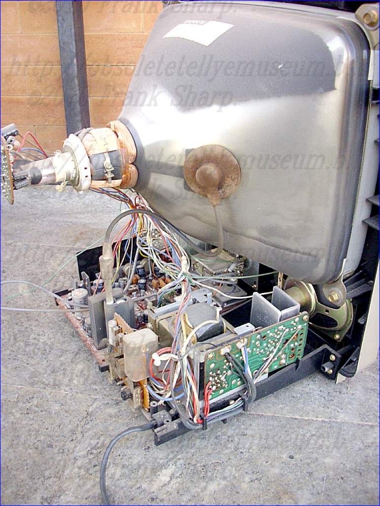
On left side all receiver functions on a monocarrier PCB with even an IC.
On right side the power supply section
Front side the tuner selectors.
CRT TUBE SONY CT-512R G7 E 2T
The tuning circuits has a large knob potentiometers tuning system which use voltage controlled capacitances such as varactor diodes as the frequency determining elements.
Therefore a stable AFC circuit is developed:
 A
superheterodyne receiver having an automatic intermediate
frequency control circuit with means to prevent the faulty
regulation thereof. The receiver has means for receiving a radio
frequency signal and mixing the same with the output of a
superheterodyne oscillator. This produces an intermediate frequency
signal which is coupled to a frequency or phase discriminator to
produce an error signal for controlling the frequency of the
superheterodyne oscillator. A regulation circuit is provided having
an electronic switch to interrupt the feedback circuit when only
unwanted frequencies tend to produce faulty regulation of the
superheterodyne oscillator.
A
superheterodyne receiver having an automatic intermediate
frequency control circuit with means to prevent the faulty
regulation thereof. The receiver has means for receiving a radio
frequency signal and mixing the same with the output of a
superheterodyne oscillator. This produces an intermediate frequency
signal which is coupled to a frequency or phase discriminator to
produce an error signal for controlling the frequency of the
superheterodyne oscillator. A regulation circuit is provided having
an electronic switch to interrupt the feedback circuit when only
unwanted frequencies tend to produce faulty regulation of the
superheterodyne oscillator.
Power supply is realized with mains transformer and Linear transistorized power supply stabilizer, A DC power supply apparatus includes a rectifier circuit which rectifies an input commercial AC voltage. The rectifier output voltage is smoothed in a smoothing capacitor. Voltage stabilization is provided in the stabilizing circuits by the use of Zener diode circuits to provide biasing to control the collector-emitter paths of respective transistors.A linear regulator circuit according to an embodiment of the present invention has an input node receiving an unregulated voltage and an output node providing a regulated voltage. The linear regulator circuit includes a voltage regulator, a bias circuit, and a current control device.
In one embodiment, the current control device is implemented as an NPN bipolar junction transistor (BJT) having a collector electrode forming the input node of the linear regulator circuit, an emitter electrode coupled to the input of the voltage regulator, and a base electrode coupled to the second terminal of the bias circuit. A first capacitor may be coupled between the input and reference terminals of the voltage regulator and a second capacitor may be coupled between the output and reference terminals of the voltage regulator. The voltage regulator may be implemented as known to those skilled in the art, such as an LDO or non-LDO 3-terminal regulator or the like.
The bias circuit may include a bias device and a current source. The bias device has a first terminal coupled to the output terminal of the voltage regulator and a second terminal coupled to the control electrode of the current control device. The current source has an input coupled to the first current electrode of the current control device and an output coupled to the second terminal of the bias device. A capacitor may be coupled between the first and second terminals of the bias device.
In the bias device and current source embodiment, the bias device may be implemented as a Zener diode, one or more diodes coupled in series, at least one light emitting diode, or any other bias device which develops sufficient voltage while receiving current from the current source. The current source may be implemented with a PNP BJT having its collector electrode coupled to the second terminal of the bias device, at least one first resistor having a first end coupled to the emitter electrode of the PNP BJT and a second end, a Zener diode and a second resistor. The Zener diode has an anode coupled to the base electrode of the PNP BJT and a cathode coupled to the second end of the first resistor. The second resistor has a first end coupled to the anode of the Zener diode and a second end coupled to the reference terminal of the voltage regulator. A second Zener diode may be included having an anode coupled to the cathode of the first Zener diode and a cathode coupled to the first current electrode of the current control device.
 A circuit is disclosed for improving
operation of a linear regulator, having an input terminal, an
output terminal, and a reference terminal. The circuit includes an
input node, a transistor, a bias circuit, and first and second
capacitors. The transistor has a first current electrode coupled to
the input node, a second current electrode for coupling to the
input terminal of the linear regulator, and a control electrode. The
bias circuit has a first terminal for coupling to the output
terminal of the linear regulator and a second terminal coupled to
the control electrode of the transistor. The first capacitor is for
coupling between the input and reference terminals of the linear
regulator, and the second capacitor is for coupling between the
output and reference terminals of the linear regulator. The bias
circuit develops a voltage sufficient to drive the control terminal
of the transistor and to operate the linear regulator. The bias
circuit may be a battery, a bias device and a current source, a
floating power supply, a charge pump, or any combination thereof.
The transistor may be implemented as a BJT or FET or any other
suitable current controlled device.
A circuit is disclosed for improving
operation of a linear regulator, having an input terminal, an
output terminal, and a reference terminal. The circuit includes an
input node, a transistor, a bias circuit, and first and second
capacitors. The transistor has a first current electrode coupled to
the input node, a second current electrode for coupling to the
input terminal of the linear regulator, and a control electrode. The
bias circuit has a first terminal for coupling to the output
terminal of the linear regulator and a second terminal coupled to
the control electrode of the transistor. The first capacitor is for
coupling between the input and reference terminals of the linear
regulator, and the second capacitor is for coupling between the
output and reference terminals of the linear regulator. The bias
circuit develops a voltage sufficient to drive the control terminal
of the transistor and to operate the linear regulator. The bias
circuit may be a battery, a bias device and a current source, a
floating power supply, a charge pump, or any combination thereof.
The transistor may be implemented as a BJT or FET or any other
suitable current controlled device.
- The EHT Output is realized with a selenium rectifier.
 The EHT selenium rectifier which is a Specially designed selenium rectifiers were once widely used as EHT
rectifiers in television sets and photocopiers. A layer of selenium
was applied to a sheet of soft iron foil, and thousands of tiny discs
(typically 2mm diameter) were punched out of this and assembled as
"stacks" inside ceramic tubes. Rectifiers capable of supplying tens of
thousands of volts could be made this way. Their internal resistance was
extremely high, but most EHT applications only required a few hundred
microamps at most, so this was not normally an issue. With the
development of inexpensive high voltage silicon rectifiers, this
technology has fallen into disuse.A selenium rectifier is a type
of metal rectifier, invented in 1933. They were used to replace vacuum
tube rectifiers in power supplies for electronic equipment, and in high
current battery charger applications.
The EHT selenium rectifier which is a Specially designed selenium rectifiers were once widely used as EHT
rectifiers in television sets and photocopiers. A layer of selenium
was applied to a sheet of soft iron foil, and thousands of tiny discs
(typically 2mm diameter) were punched out of this and assembled as
"stacks" inside ceramic tubes. Rectifiers capable of supplying tens of
thousands of volts could be made this way. Their internal resistance was
extremely high, but most EHT applications only required a few hundred
microamps at most, so this was not normally an issue. With the
development of inexpensive high voltage silicon rectifiers, this
technology has fallen into disuse.A selenium rectifier is a type
of metal rectifier, invented in 1933. They were used to replace vacuum
tube rectifiers in power supplies for electronic equipment, and in high
current battery charger applications.
The photoelectric and rectifying properties of selenium were observed by C. E. Fitts around 1886 but practical rectifier devices were not manufactured routinely until the 1930s. Compared with the earlier copper oxide rectifier, the selenium cell could withstand higher voltage but at a lower current capacity per unit area.
Furthermore all semiconductors are SONY made, even an example how JAPANESE technology was forwarding all other markets in the world expecially Euro and USA.
On left side all receiver functions on a monocarrier PCB with even an IC.
On right side the power supply section
Front side the tuner selectors.
CRT TUBE SONY CT-512R G7 E 2T
The tuning circuits has a large knob potentiometers tuning system which use voltage controlled capacitances such as varactor diodes as the frequency determining elements.
Therefore a stable AFC circuit is developed:
 A
superheterodyne receiver having an automatic intermediate
frequency control circuit with means to prevent the faulty
regulation thereof. The receiver has means for receiving a radio
frequency signal and mixing the same with the output of a
superheterodyne oscillator. This produces an intermediate frequency
signal which is coupled to a frequency or phase discriminator to
produce an error signal for controlling the frequency of the
superheterodyne oscillator. A regulation circuit is provided having
an electronic switch to interrupt the feedback circuit when only
unwanted frequencies tend to produce faulty regulation of the
superheterodyne oscillator.
A
superheterodyne receiver having an automatic intermediate
frequency control circuit with means to prevent the faulty
regulation thereof. The receiver has means for receiving a radio
frequency signal and mixing the same with the output of a
superheterodyne oscillator. This produces an intermediate frequency
signal which is coupled to a frequency or phase discriminator to
produce an error signal for controlling the frequency of the
superheterodyne oscillator. A regulation circuit is provided having
an electronic switch to interrupt the feedback circuit when only
unwanted frequencies tend to produce faulty regulation of the
superheterodyne oscillator.
Power supply is realized with mains transformer and Linear transistorized power supply stabilizer, A DC power supply apparatus includes a rectifier circuit which rectifies an input commercial AC voltage. The rectifier output voltage is smoothed in a smoothing capacitor. Voltage stabilization is provided in the stabilizing circuits by the use of Zener diode circuits to provide biasing to control the collector-emitter paths of respective transistors.A linear regulator circuit according to an embodiment of the present invention has an input node receiving an unregulated voltage and an output node providing a regulated voltage. The linear regulator circuit includes a voltage regulator, a bias circuit, and a current control device.
In one embodiment, the current control device is implemented as an NPN bipolar junction transistor (BJT) having a collector electrode forming the input node of the linear regulator circuit, an emitter electrode coupled to the input of the voltage regulator, and a base electrode coupled to the second terminal of the bias circuit. A first capacitor may be coupled between the input and reference terminals of the voltage regulator and a second capacitor may be coupled between the output and reference terminals of the voltage regulator. The voltage regulator may be implemented as known to those skilled in the art, such as an LDO or non-LDO 3-terminal regulator or the like.
The bias circuit may include a bias device and a current source. The bias device has a first terminal coupled to the output terminal of the voltage regulator and a second terminal coupled to the control electrode of the current control device. The current source has an input coupled to the first current electrode of the current control device and an output coupled to the second terminal of the bias device. A capacitor may be coupled between the first and second terminals of the bias device.
In the bias device and current source embodiment, the bias device may be implemented as a Zener diode, one or more diodes coupled in series, at least one light emitting diode, or any other bias device which develops sufficient voltage while receiving current from the current source. The current source may be implemented with a PNP BJT having its collector electrode coupled to the second terminal of the bias device, at least one first resistor having a first end coupled to the emitter electrode of the PNP BJT and a second end, a Zener diode and a second resistor. The Zener diode has an anode coupled to the base electrode of the PNP BJT and a cathode coupled to the second end of the first resistor. The second resistor has a first end coupled to the anode of the Zener diode and a second end coupled to the reference terminal of the voltage regulator. A second Zener diode may be included having an anode coupled to the cathode of the first Zener diode and a cathode coupled to the first current electrode of the current control device.
A circuit is disclosed for improving
operation of a linear regulator, having an input terminal, an
output terminal, and a reference terminal. The circuit includes an
input node, a transistor, a bias circuit, and first and second
capacitors. The transistor has a first current electrode coupled to
the input node, a second current electrode for coupling to the
input terminal of the linear regulator, and a control electrode. The
bias circuit has a first terminal for coupling to the output
terminal of the linear regulator and a second terminal coupled to
the control electrode of the transistor. The first capacitor is for
coupling between the input and reference terminals of the linear
regulator, and the second capacitor is for coupling between the
output and reference terminals of the linear regulator. The bias
circuit develops a voltage sufficient to drive the control terminal
of the transistor and to operate the linear regulator. The bias
circuit may be a battery, a bias device and a current source, a
floating power supply, a charge pump, or any combination thereof.
The transistor may be implemented as a BJT or FET or any other
suitable current controlled device.
- The EHT Output is realized with a selenium rectifier.
The EHT selenium rectifier which is a Specially designed selenium rectifiers were once widely used as EHT
rectifiers in television sets and photocopiers. A layer of selenium
was applied to a sheet of soft iron foil, and thousands of tiny discs
(typically 2mm diameter) were punched out of this and assembled as
"stacks" inside ceramic tubes. Rectifiers capable of supplying tens of
thousands of volts could be made this way. Their internal resistance was
extremely high, but most EHT applications only required a few hundred
microamps at most, so this was not normally an issue. With the
development of inexpensive high voltage silicon rectifiers, this
technology has fallen into disuse.A selenium rectifier is a type
of metal rectifier, invented in 1933. They were used to replace vacuum
tube rectifiers in power supplies for electronic equipment, and in high
current battery charger applications.
The photoelectric and rectifying properties of selenium were observed by C. E. Fitts around 1886 but practical rectifier devices were not manufactured routinely until the 1930s. Compared with the earlier copper oxide rectifier, the selenium cell could withstand higher voltage but at a lower current capacity per unit area.
No comments:
Post a Comment
The most important thing to remember about the Comment Rules is this:
The determination of whether any comment is in compliance is at the sole discretion of this blog’s owner.
Comments on this blog may be blocked or deleted at any time.
Fair people are getting fair reply. Spam and useless crap and filthy comments / scrapers / observations goes all directly to My Private HELL without even appearing in public !!!
The fact that a comment is permitted in no way constitutes an endorsement of any view expressed, fact alleged, or link provided in that comment by the administrator of this site.
This means that there may be a delay between the submission and the eventual appearance of your comment.
Requiring blog comments to obey well-defined rules does not infringe on the free speech of commenters.
Resisting the tide of post-modernity may be difficult, but I will attempt it anyway.
Your choice.........Live or DIE.
That indeed is where your liberty lies.
Note: Only a member of this blog may post a comment.