


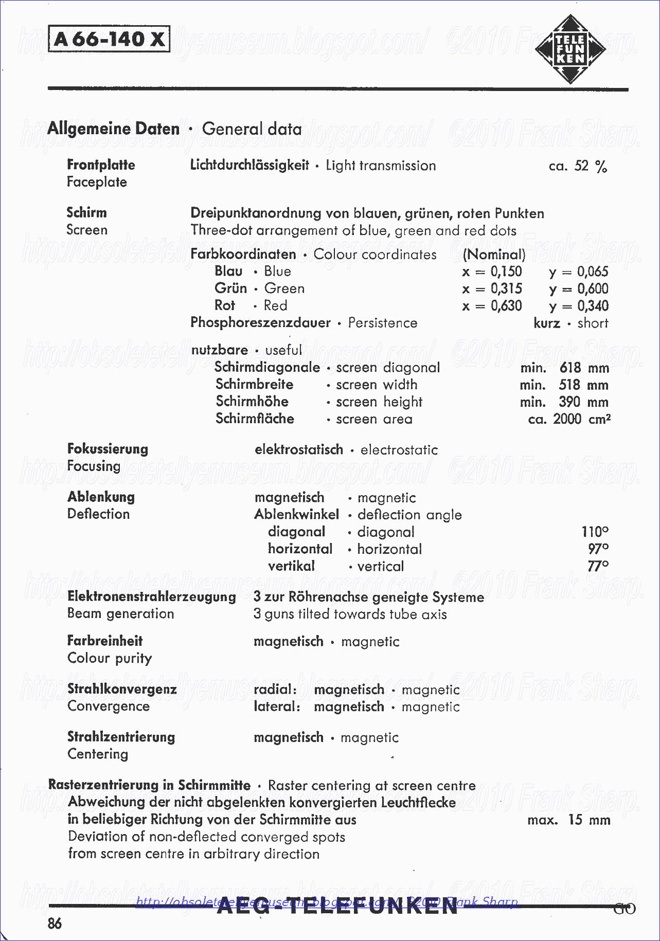
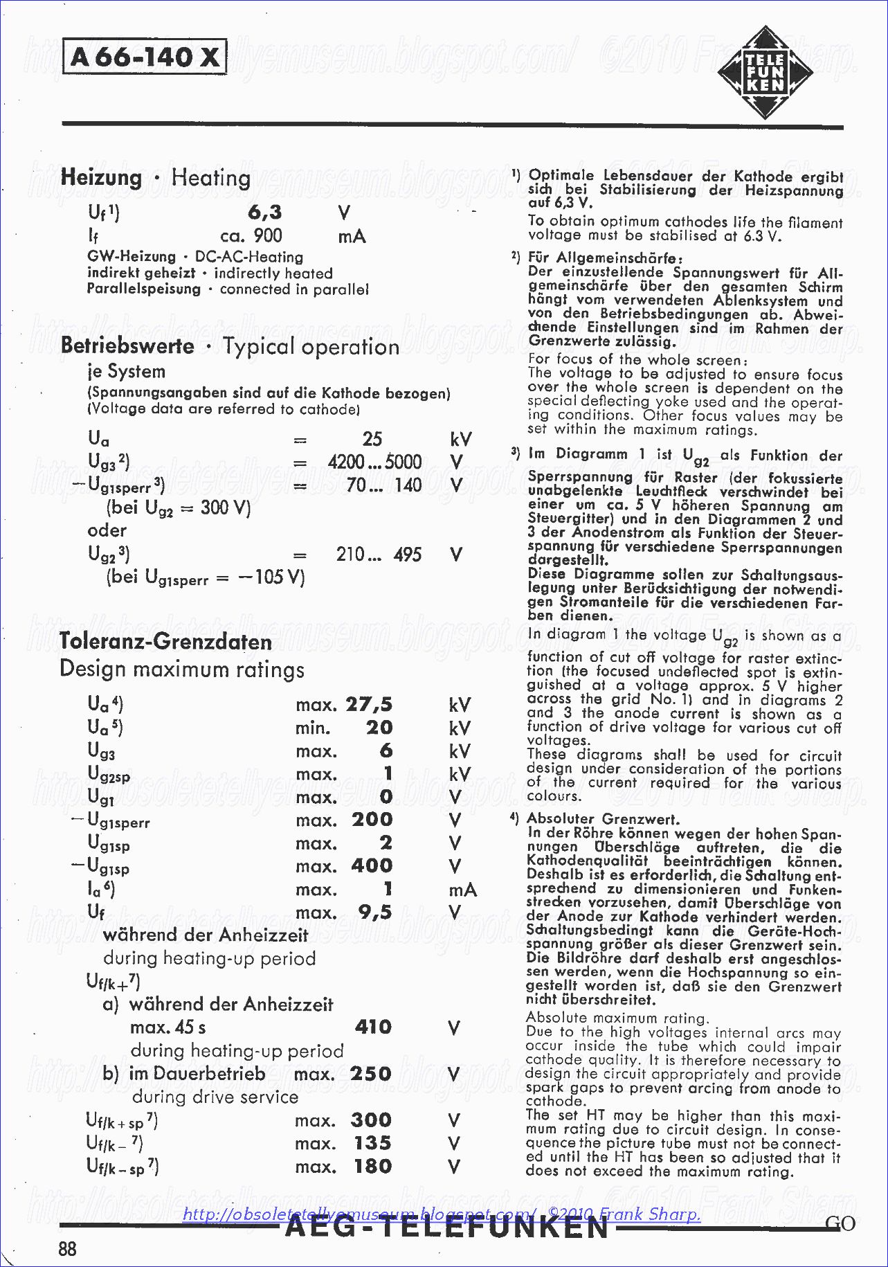
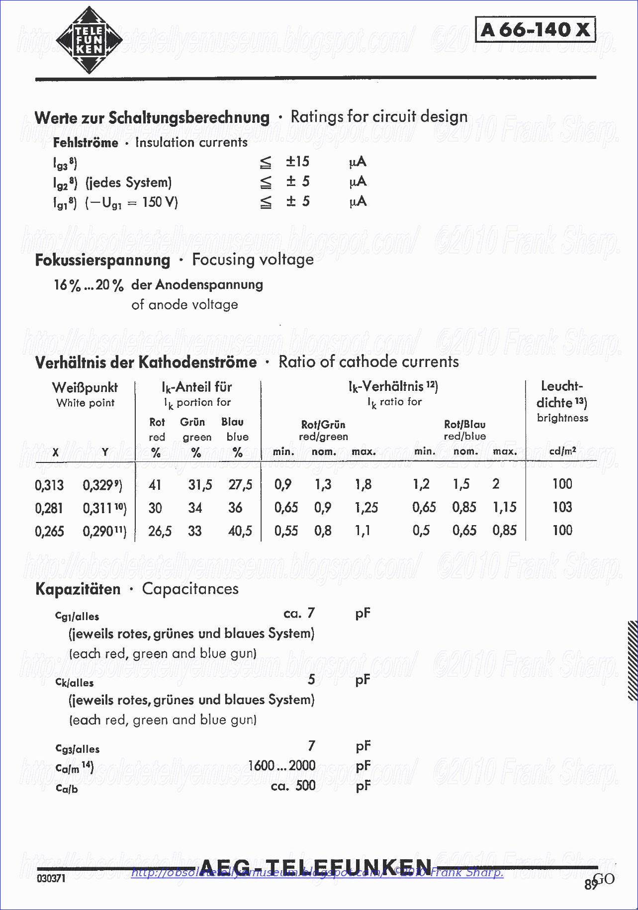
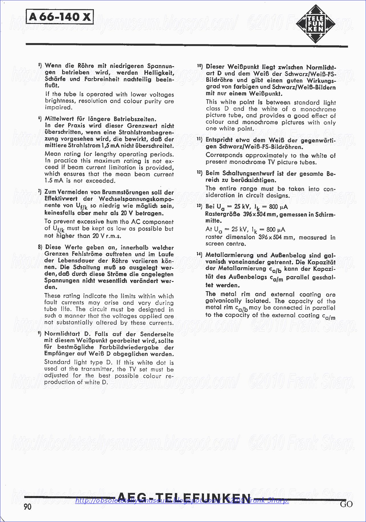
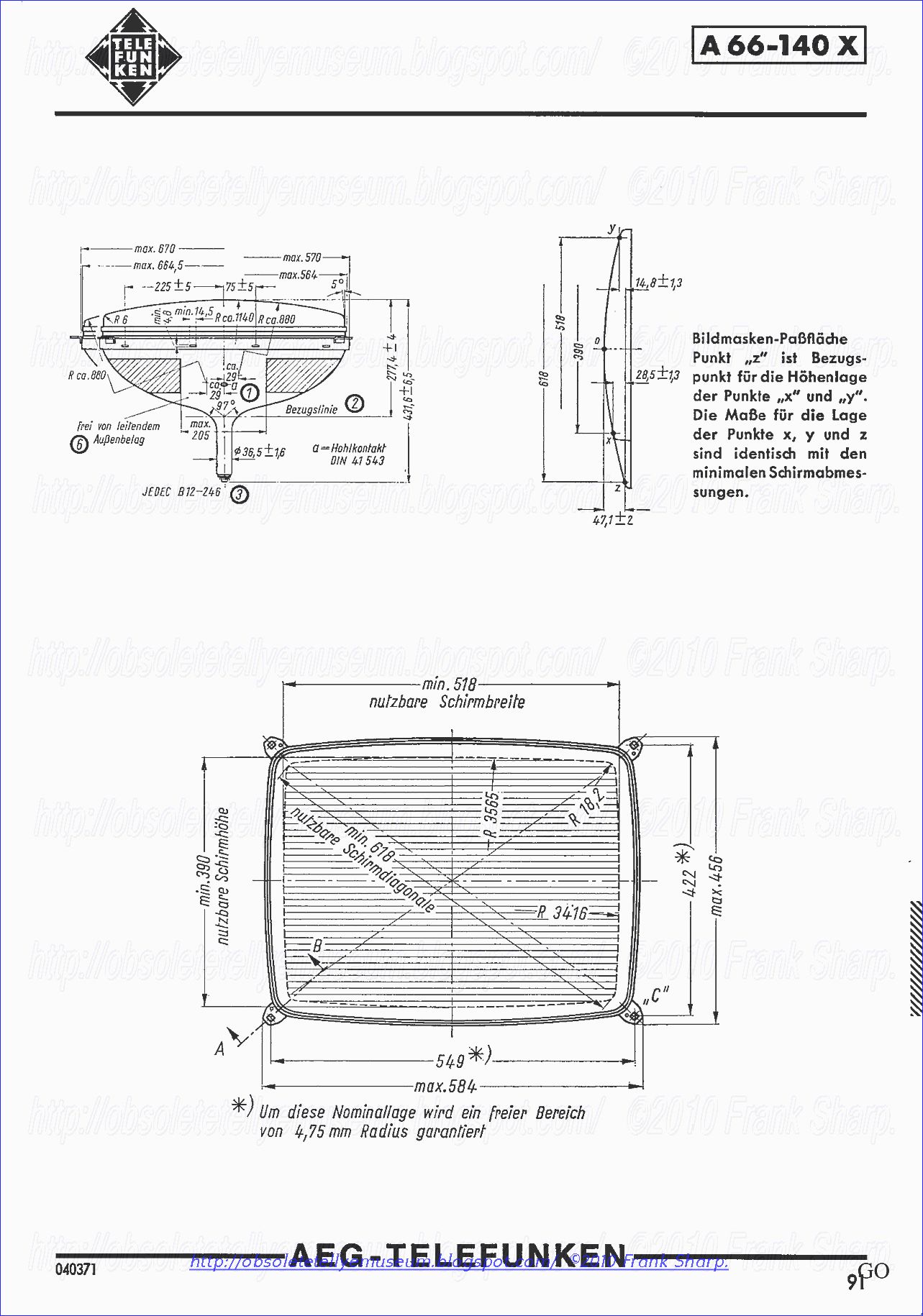
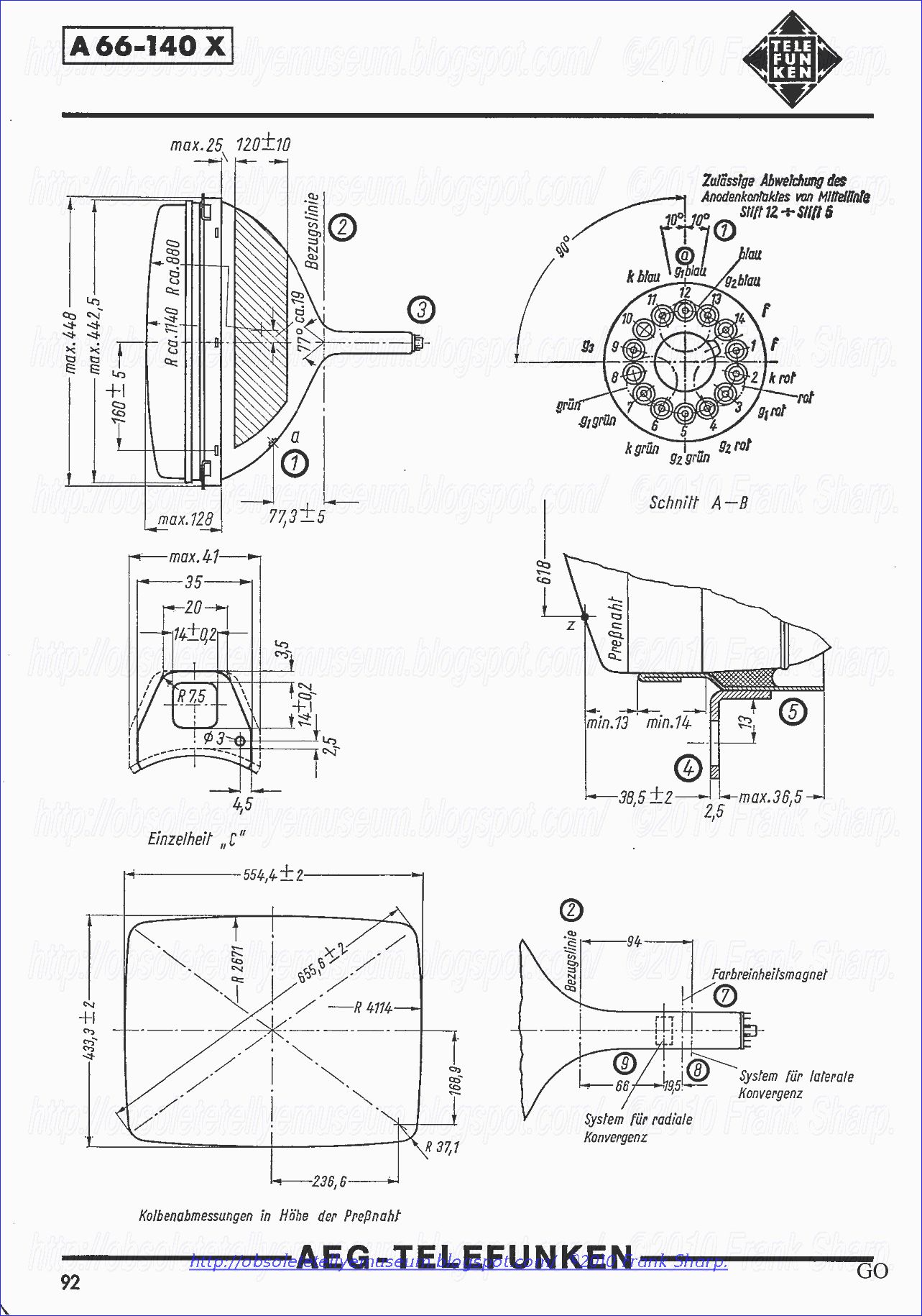
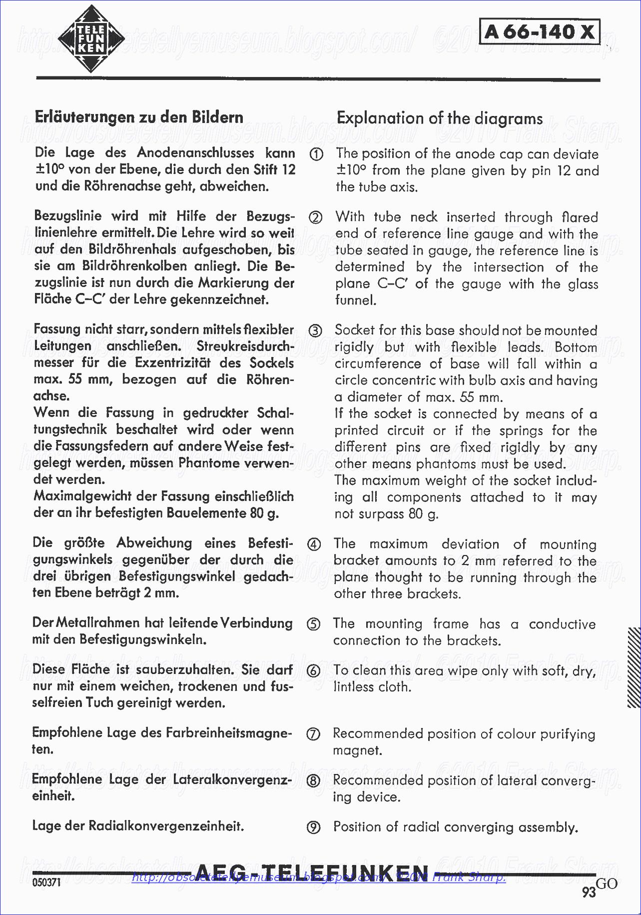
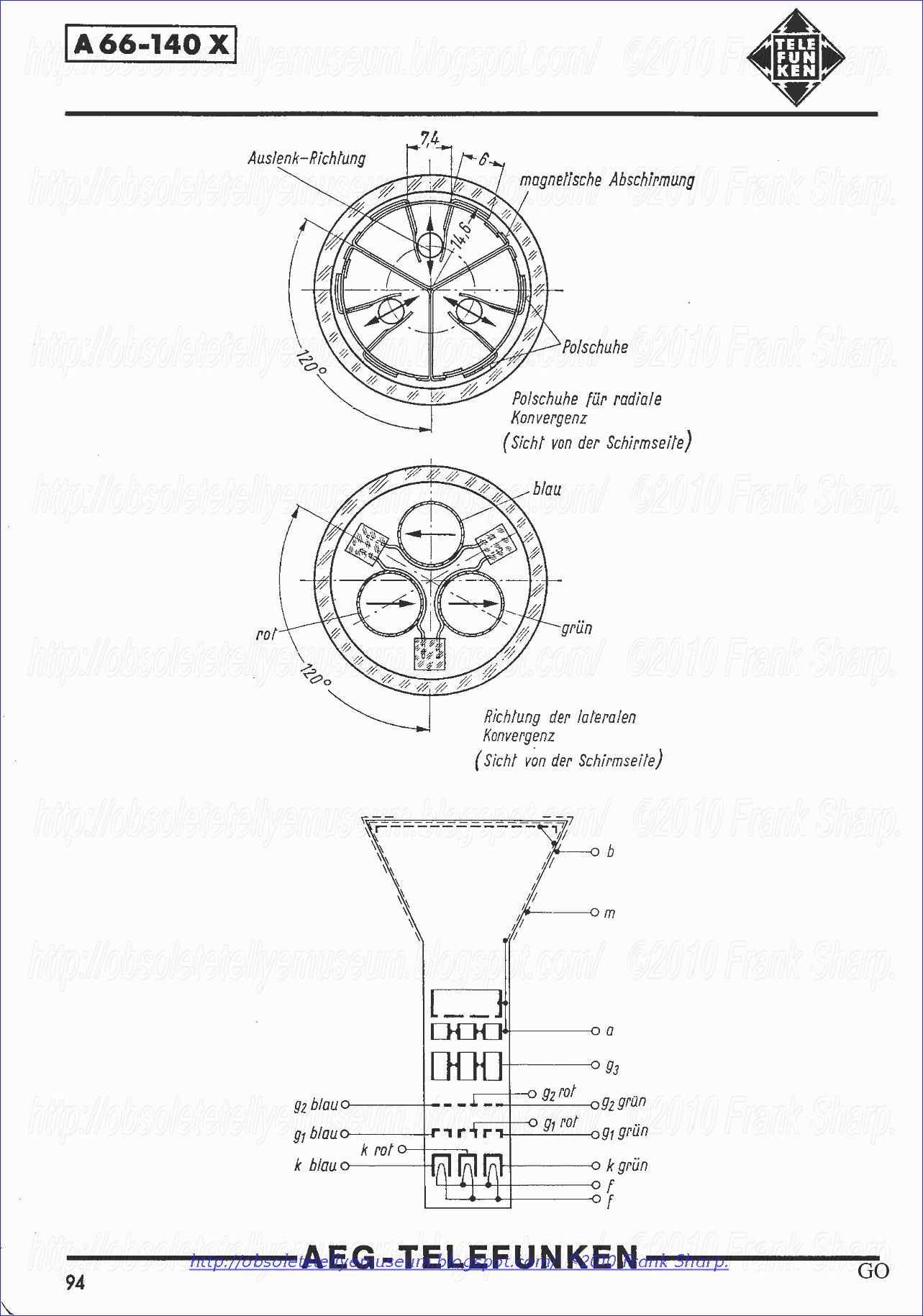
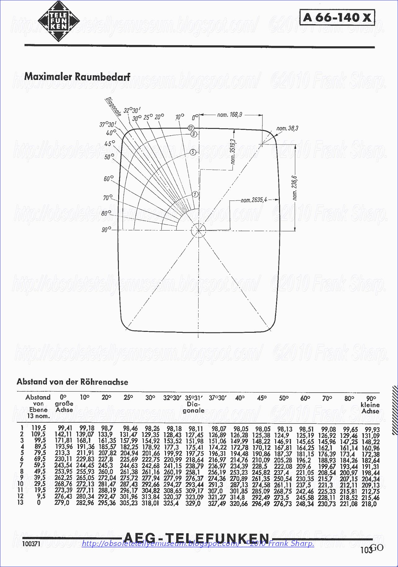
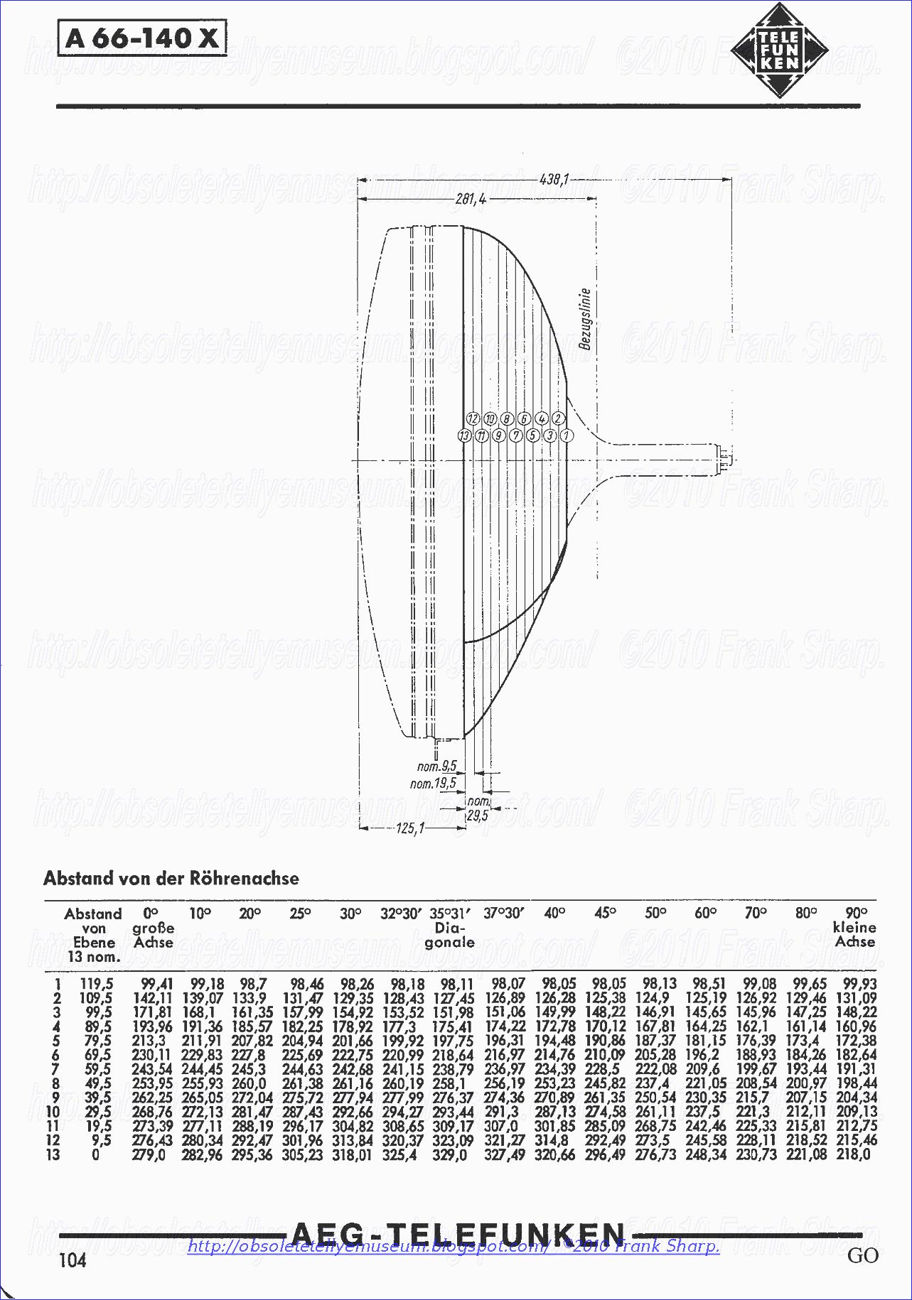
CRT TUBE TELEFUNKEN A66-140X.
DEFLECTION UNIT TELEFUNKEN AS110K213
As is well known to those skilled in this art, the delta-gun, color cathode ray tube (CRT) differs most significantly from conventional CRT's having a single gun in that the delta-gun has three guns, each of which generate a distinct electron beam for exciting its corresponding phosphor dot of the red, green and blue dot triad matrix constituting the CRT display surface.
Each of the delta-arranged gun beams must land at precisely the same opening in the shadow mask at every point on the screen in order to produce a perfect rendition of a desired color and symbol shape. To achieve the desired rendition on the screen, the beams, substantially forward of where they leave the guns, are magnetically deflected, as a set, by excitation of a main deflection yoke comprising an electromagnet arrangement mounted around the neck of the CRT so as to control the angle at which the beams, as a set, approach the desired landing site on the display screen.
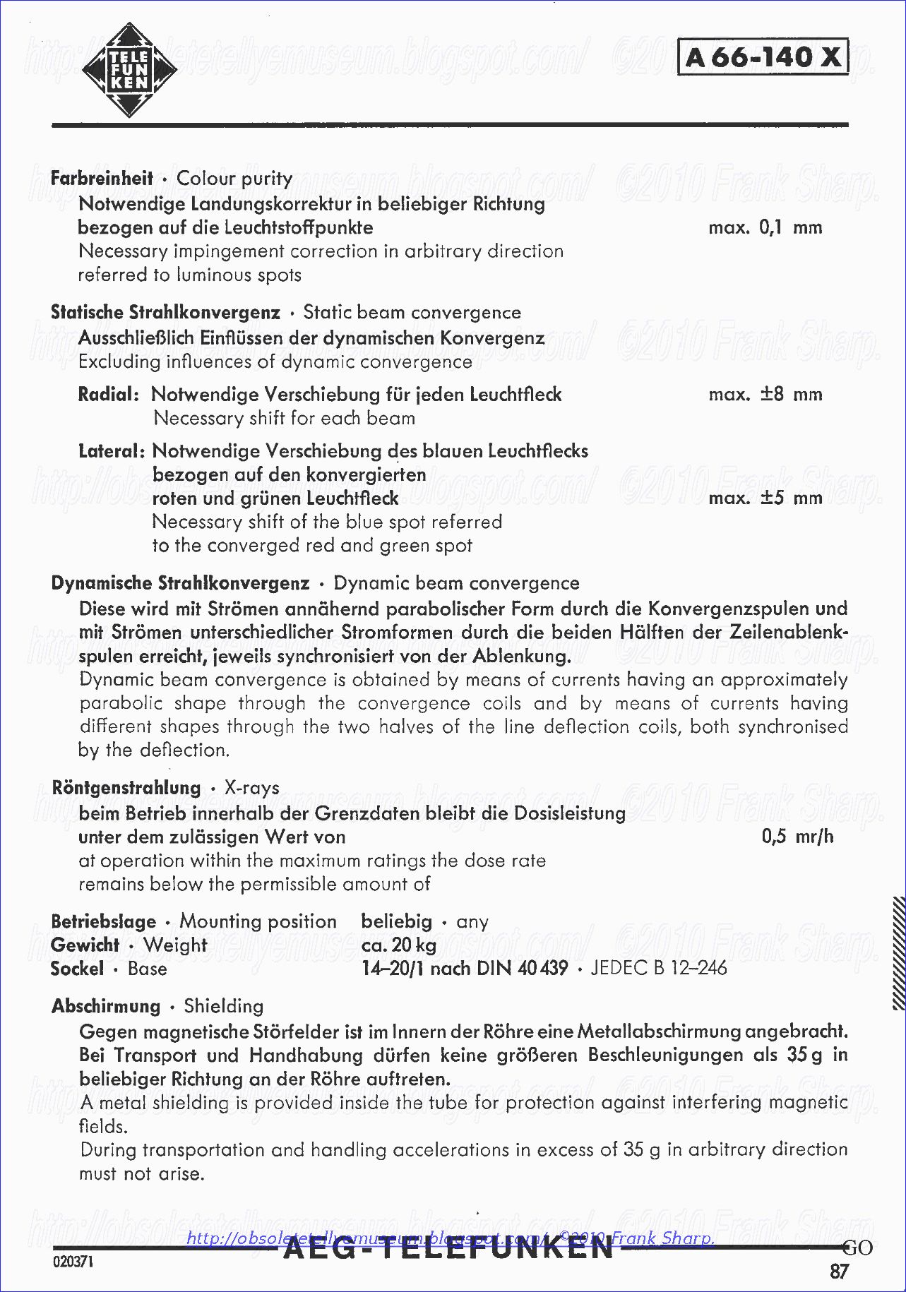
Registration of all three beams at the landing site cannot be accomplished through all deflection angles without some individual deflection of each beam in addition to the main deflection. The auxiliary deflection system is termed convergence deflection because of the function it performs in causing each beam to converge to a single point for all deflected angles.
Aside from the geometry errors (pin cushion effect) which necessitate a convergence system, there are errors due primarily to alignment tolerances associated with the deflection yoke and electron gun assemblies. These errors have the effect of distorting the ideal convergence function and consequently, each CRT assembly must be uniquely converged.
In most, if not all delta-gun CRT's, convergence deflection is accomplished by electrical current excitation of a small deflection yoke for each yoke is usually part of the electron gun assembly .
Each of these yokes produce a magnetic field which is applied to the beam emanating from their respective gun in such a way that deflection of the beam is along a single axis, that is, the axis which extends radially from the center of the CRT, through the center of each of the three guns. These axes are called red radial, green radial and blue radial, for a typical CRT and are then, by the nature of the delta-gun, 120 angular degrees apart.
It is customary to align the blue radial with the vertical deflection of the main deflection yoke. Thus, as facing the front of the CRT, the blue gun converges along a vertical axis, red along an axis 120° left and green along an axis 120° to the right (240° to the left).
The full function of convergence is not possible without a fourth degree of freedom of movement associated with one of the electron beams. This is generally applied to the blue gun along the lateral axis of the CRT at 90° to the blue radial and is consequently termed blue lateral convergence.
As is the case with radial convergence, the blue lateral convergence can be partitioned into two components, a dynamic portion and a static, or constant portion. The cynamic portion of blue lateral correction (unlike that of the dynamic portion of the radial correction) can be, in general, performed by the design of the main deflection yoke. When this is the case, only an adjustable external static magnet is required to position the blue beam laterally to a reference location at the center of the screen. This magnetic adjustment is termed the static blue lateral adjustment.
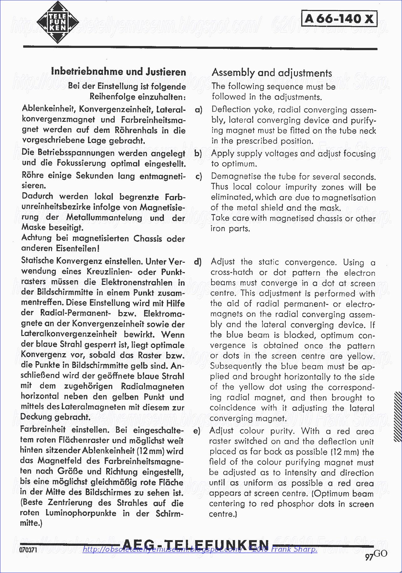
CRT TUBE TELEFUNKEN A66-140X Assembly and adjustments
The following sequence must be followed in the adjustments.
a)
Deflection yoke, radial converging assembly, lateral converging device and purifying magnet must be fitted on the tube neck in the prescribed position.
b)
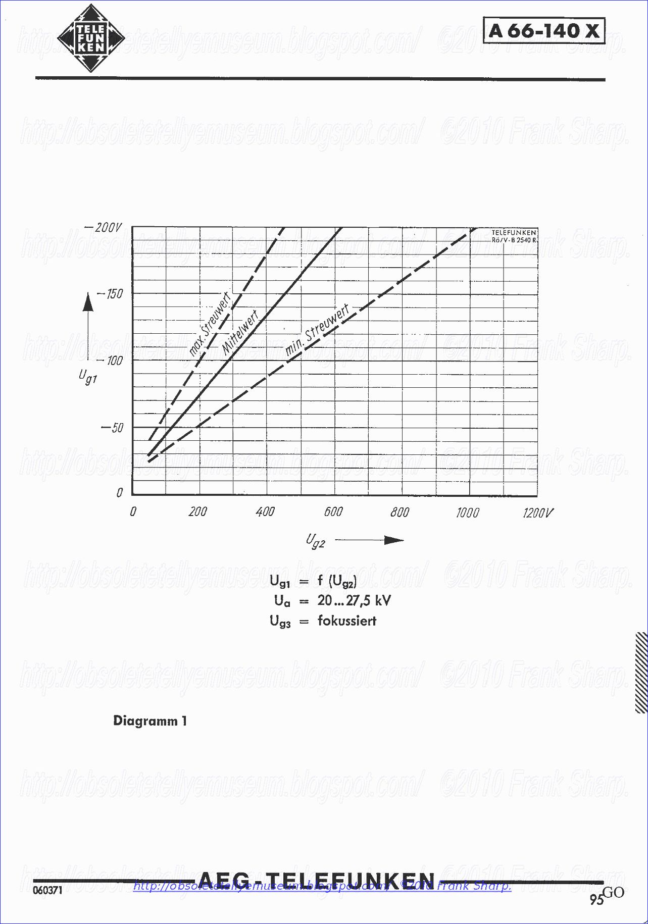
Apply supply voltages and adjust focusing to Optimum.
c)
Demagnetize the tube for several seconds. Thus local colour impurity zones will be eliminated, which are due to magnetization of the metal shield and the mask. Take care with magnetized chassis or other iron parts.
d)
Adjust the static convergence. Using a cross-hatch or dot pattern the electron beams must converge in a dot at screen centre. This adjustment is performed with the aid of radial permanent or electromagnets on the radial converging assembly and the lateral converging device. If the blue beam is blocked, Optimum convergence is obtained once the pattern or dots in the screen centre are yellow. Subsequently the blue beam must be applied and brought horizontally to the side of the yellow dot using the corresponding radial magnet, and then brought to coincidence with it adjusting the lateral converging magnet.
e)
Adjust colour purity. With a red area raster switched on and the deflection unit placed as for back as possible (12 mm) the field of the colour purifying magnet must be adjusted as to intensity and direction until as uniform as possible c red area appears at screen centre. (Optimum beam centering to red phosphor dots in screen centre.)
)
Push the deflection unit forwards until the entire screen is illuminated with o uniform red. Subsequently the colour purity of the green and blue rasters must be checked Over the whole screen and, if necessary, a compromise must be found in the adjustment for all colours. Prior to, and following, each colour purity adjustment the static convergence must be checked. Centre a test pattern by means of DC pre deflection. Check static convergence as well as colour purity and readjust if necessary.
Adjustment of dynamic convergence.
Use a bright cross-hatch or dot pattern for this purpose. By adjusting the alternating currents in the converging coils the three coloured pattern must be brought to coincidence Over the entire screen (without the Corners) in such a manner that white dots or pattern lines are produced. After blocking the blue beam adjust the red a n d green roster to coincidence. During this procedure the static convergence must be readjusted and the colour purity checked several times. By regulating the corner convergence currents in the deflection coils raster coverage is performed in the corners as next Step. In conclusion pincushion distortion must be eliminated. Care must be token that at no time o considerable amount of beam current reaches the walls of the tube or ports of the electron gun.
Adjusting colour purity with o microscope
Observation of register through a microscope (magnification approx. 40) is recommended for colour purity adjustment. For this purpose a white raster is used. The phosphor dots must be illuminated from the side with a light source (e. g. lamp). In the screen centre the beam position is influenced by means of the purifying magnet in such manner that the centres of the two triangles, which are formed by a phosphor triplet and the excited surfaces, are in coincidence. Afterwards the convergence must be checked and readjusted if necessary, the colour purity likewise being corrected once more. After switching to red raster o uniform red screen surface must be adjusted as described in e) by sliding the deflecting yoke axially.
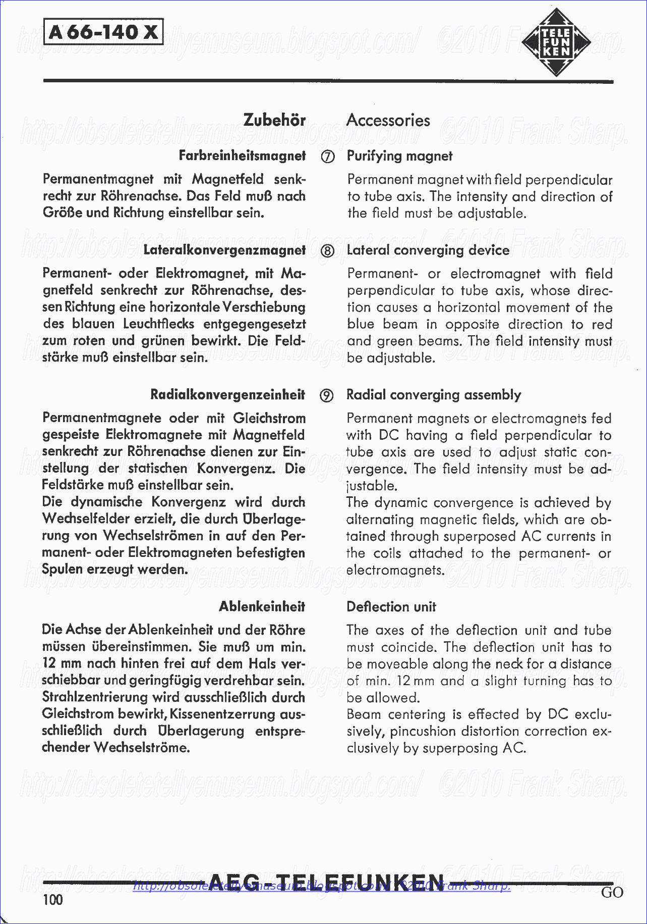
Purifying magnet
Permanent magnet with field perpendicular to tube axis. The intensity and direction of the field must be adjustable. Lateral converging device Permanent- or electromagnet with field perpendicular to tube axis, whose direction causes a horizontal movement of the blue beam in opposite direction to red and green beams. The field intensity must be adjustable. Radial converging assembly Permanent magnets or electromagnet fed with DC having a field perpendicular to tube axis are used to adjust static convergence. The field intensity must be adjustable. The dynamic convergence is achieved by alternating magnetic fields, which are obtained through superposed AC currents in the coils attached to the permanent- or electromagnets.
Deflection unit
The axes of the deflection unit and tube must coincide. The deflection unit has to be movable along the neck for a distance of min. 12 mm and a slight turning has to be allowed. Beam centering is effected by DC exclusively, pincushion distortion correction exclusively by superposing AC.

METHOD AND APPARATUS FOR STATIC AND DYNAMIC CONVERGENCE IN A DELTA GUN CRT COLOR TUBE:
The three electron beams in a color television cathode ray tube are
statically converged at the beginning and end of vertical and
horizontal scan lines, and are dynamically converged in the center
of the raster. Each external convergence assembly, mounted adjacent a
pair of internal pole pieces for a corresponding electron beam,
includes a single coil passing both vertical and horizontal
convergence currents which have been combined by a semiconductor
circuit. The convergence coil for the blue beam is split into two
sections which are separately excited to independently control
lateral movement on o pposite
sides of the raster. The convergence method uses active circuits,
and simplified passive circuits which require a reduced number of
input waveforms from the receiver scanning stages, such as the
waveform across the S shaping capacitor.
1. In a color television receiver having a cathode ray tube with
plural electron beams and scanning means for deflecting said plural
electron beams to produce scanning lines, a convergence system,
comprising: 2. The convergence
system of claim 1 wherein said static convergence means statically
converges said plural electron beams at opposite edges of said
scanning lines, said dynamic convergence means causes said plural
electron beams when not coincident to have an arcuate path with a
maximum deviation from a straight path in the vicinity of said
center portion. 3. The
convergence system of claim 2 wherein said adjustable means includes
vertical line adjustable means for laterally moving vertical
scanning lines and horizontal line adjustable means for laterally
moving horizontal scanning lines, the pair of line adjustable means
producing maximum correction deflection during said center portion
of scan and progressively lesser amounts of correction deflection in
opposite directions away from said center portion of scan.
4. The convergence system of claim 1
wherein said scanning means comprises vertical deflection means for
producing vertical signals synchronized with the vertical deflection
of said electron beams and horizontal deflection means for
producing horizontal signals synchronized with the horizontal
deflection of said electron beams, said dynamic convergence means
including vertical generator means having an input coupled to said
vertical deflection means for converting the vertical signals into a
generally parabolic waveform having a maximum deviation at the center
of each vertical scanning line and vertical adjustable means for
varying the amount of said maximum deviation, horizontal generator
means having an input coupled to said horizontal deflection means for
converting the horizontal signals into a generally parabolic
waveform having a maximum deviation at the center of each horizontal
scanning line and horizontal adjustable means for varying the
amount of said maximum deviation, and exciter means responsive to
said parabolic waveforms for producing corresponding deflections in
the scanning lines. 5. The
convergence system of claim 4 wherein at least one of said generator
means includes a pair of active devices each having an input and an
output and connected as amplifiers, input means coupled to the
inputs for driving said pair of devices oppositely by a generally
sawtooth shaped waveform occurring in synchronism with said
synchronized signal, and output means coupled to the outputs of said
pair of devices for deriving said generally parabolic waveform.
6. The convergence system of claim
5 wherein said amplifiers include capacitive feedback means coupled
between the output and the input of said pair of devices to cause
said devices to convert the generally sawtooth shaped waveform into
the generally parabolic waveform.
7. The convergence system of claim 4 wherein said exciter means
comprises a convergence assembly external to said cathode ray tube and
adjacent one of said plural electron beams for applying convergence
correction thereto, said assembly includes a coil for generating a
magnetic flux field which produces said correction, and said dynamic
convergence means includes mixer means for combining the generally
parabolic waveform from said vertical generator means and the
generally parabolic waveform from said horizontal generator means to
produce a combined convergence waveform coupled to said coil.
8. The converge
pposite
sides of the raster. The convergence method uses active circuits,
and simplified passive circuits which require a reduced number of
input waveforms from the receiver scanning stages, such as the
waveform across the S shaping capacitor.
1. In a color television receiver having a cathode ray tube with
plural electron beams and scanning means for deflecting said plural
electron beams to produce scanning lines, a convergence system,
comprising: 2. The convergence
system of claim 1 wherein said static convergence means statically
converges said plural electron beams at opposite edges of said
scanning lines, said dynamic convergence means causes said plural
electron beams when not coincident to have an arcuate path with a
maximum deviation from a straight path in the vicinity of said
center portion. 3. The
convergence system of claim 2 wherein said adjustable means includes
vertical line adjustable means for laterally moving vertical
scanning lines and horizontal line adjustable means for laterally
moving horizontal scanning lines, the pair of line adjustable means
producing maximum correction deflection during said center portion
of scan and progressively lesser amounts of correction deflection in
opposite directions away from said center portion of scan.
4. The convergence system of claim 1
wherein said scanning means comprises vertical deflection means for
producing vertical signals synchronized with the vertical deflection
of said electron beams and horizontal deflection means for
producing horizontal signals synchronized with the horizontal
deflection of said electron beams, said dynamic convergence means
including vertical generator means having an input coupled to said
vertical deflection means for converting the vertical signals into a
generally parabolic waveform having a maximum deviation at the center
of each vertical scanning line and vertical adjustable means for
varying the amount of said maximum deviation, horizontal generator
means having an input coupled to said horizontal deflection means for
converting the horizontal signals into a generally parabolic
waveform having a maximum deviation at the center of each horizontal
scanning line and horizontal adjustable means for varying the
amount of said maximum deviation, and exciter means responsive to
said parabolic waveforms for producing corresponding deflections in
the scanning lines. 5. The
convergence system of claim 4 wherein at least one of said generator
means includes a pair of active devices each having an input and an
output and connected as amplifiers, input means coupled to the
inputs for driving said pair of devices oppositely by a generally
sawtooth shaped waveform occurring in synchronism with said
synchronized signal, and output means coupled to the outputs of said
pair of devices for deriving said generally parabolic waveform.
6. The convergence system of claim
5 wherein said amplifiers include capacitive feedback means coupled
between the output and the input of said pair of devices to cause
said devices to convert the generally sawtooth shaped waveform into
the generally parabolic waveform.
7. The convergence system of claim 4 wherein said exciter means
comprises a convergence assembly external to said cathode ray tube and
adjacent one of said plural electron beams for applying convergence
correction thereto, said assembly includes a coil for generating a
magnetic flux field which produces said correction, and said dynamic
convergence means includes mixer means for combining the generally
parabolic waveform from said vertical generator means and the
generally parabolic waveform from said horizontal generator means to
produce a combined convergence waveform coupled to said coil.
8. The converge nce
system of claim 1 wherein the cathode ray tube has two internal
pole pieces defining an axis equidistant therebetween through which
passes one of said plural electron beams, said dynamic convergence
means includes core means having a first leg adjacent one of said two
pole pieces and a second leg adjacent the other of said two pole
pieces, convergence coil means wound about said core means for
generating a magnetic flux field which produces the deflection of the
scanning lines in the vicinity of the center portion, and unbalance
means for producing a more concentrated magnetic flux field in one of
said legs to cause said electron beam to be deflected at a skew with
respect to the equidistant axis.
9. The convergence system of claim 8 wherein said unbalance means
comprises means mounting said coil means about only one of said
first and second legs. 10. The
convergence system of claim 1 wherein said dynamic convergence
means includes initial convergence means for producing an initial
correction waveform occurring during an initial portion of a
scanning period and final convergence means for producing a final
correction waveform occurring during a final portion of a scanning
period, a convergence coil for one of said electron beams having a
first winding section and a second winding section, initial
adjustable means coupled to said initial convergence means for
adjustably dividing said final correction waveform between said
first and second winding sections.
11. The convergence system of claim 10 wherein each of said
adjustable means comprises a potentiometer having a pair of end
terminals with a fixed resistance located therebetween and a wiper
movable across said fixed resistance, means separately coupling the
end terminals to said first and second winding sections, and said
wiper being coupled to the corresponding convergence means.
12. In a color television receiver
having a cathode ray tube with at least one electron beam which is
angularly deflected both vertically and horizontally by vertical
deflection means and horizontal deflection means, respectively, a
dynamic convergence system, comprising:
13. The dynamic convergence system of claim 12 wherein said
combining means includes a summing junction for combining the
horizontal and vertical correction signals, and active means coupled
between said summing junction and said single coil.
14. The dynamic convergence system of claim 12
in which said cathode ray tube includes a second electron beam
which is angularly deflected both vertically and horizontally by said
vertical deflection means and said horizontal deflection means,
respectively, a second convergence assembly external to said cathode
ray tube and adjacent said second electron beam and including second
core means having a pair of second core legs and a second single
coil wound about only one of said pair of second core legs for
generating a magnetic flux field which produces convergence
correction for said second electron beam, said combining means
includes a summing junction for combining the horizontal and vertical
correction signals, and divider means coupled between said summing
junction and said first and second coils for adjusting the ratio of
the combined signals which are impressed on said first and second
coils. 15.
nce
system of claim 1 wherein the cathode ray tube has two internal
pole pieces defining an axis equidistant therebetween through which
passes one of said plural electron beams, said dynamic convergence
means includes core means having a first leg adjacent one of said two
pole pieces and a second leg adjacent the other of said two pole
pieces, convergence coil means wound about said core means for
generating a magnetic flux field which produces the deflection of the
scanning lines in the vicinity of the center portion, and unbalance
means for producing a more concentrated magnetic flux field in one of
said legs to cause said electron beam to be deflected at a skew with
respect to the equidistant axis.
9. The convergence system of claim 8 wherein said unbalance means
comprises means mounting said coil means about only one of said
first and second legs. 10. The
convergence system of claim 1 wherein said dynamic convergence
means includes initial convergence means for producing an initial
correction waveform occurring during an initial portion of a
scanning period and final convergence means for producing a final
correction waveform occurring during a final portion of a scanning
period, a convergence coil for one of said electron beams having a
first winding section and a second winding section, initial
adjustable means coupled to said initial convergence means for
adjustably dividing said final correction waveform between said
first and second winding sections.
11. The convergence system of claim 10 wherein each of said
adjustable means comprises a potentiometer having a pair of end
terminals with a fixed resistance located therebetween and a wiper
movable across said fixed resistance, means separately coupling the
end terminals to said first and second winding sections, and said
wiper being coupled to the corresponding convergence means.
12. In a color television receiver
having a cathode ray tube with at least one electron beam which is
angularly deflected both vertically and horizontally by vertical
deflection means and horizontal deflection means, respectively, a
dynamic convergence system, comprising:
13. The dynamic convergence system of claim 12 wherein said
combining means includes a summing junction for combining the
horizontal and vertical correction signals, and active means coupled
between said summing junction and said single coil.
14. The dynamic convergence system of claim 12
in which said cathode ray tube includes a second electron beam
which is angularly deflected both vertically and horizontally by said
vertical deflection means and said horizontal deflection means,
respectively, a second convergence assembly external to said cathode
ray tube and adjacent said second electron beam and including second
core means having a pair of second core legs and a second single
coil wound about only one of said pair of second core legs for
generating a magnetic flux field which produces convergence
correction for said second electron beam, said combining means
includes a summing junction for combining the horizontal and vertical
correction signals, and divider means coupled between said summing
junction and said first and second coils for adjusting the ratio of
the combined signals which are impressed on said first and second
coils. 15.
 Dynamic
convergence correction is thus required at the beginning and end of
the horizontal and vertical scan periods. Thus, the maximum
amplitude of convergence correction current occurs at the edges of
the CRT screen. Since the convergence yoke is a current integrator,
and the rate of change of current level with time causes a
deterioration in the current waveform, this prior approach creates
problems. Since the convergence current typically increases at a
parabolic rate, the integration effect degrades convergence
performance. Furthermore, the convergence exciter assembly must also
perform as a transducer in that it must generate a magnetic field
proportional to the drive currents in its exciter coils. This creates a
considerable problem since a ferrite core is a poor magnetic
conductor at high flux densities which are required to deflect the
electron beam for proper convergence at the edge of the picture tube.
In prior systems, maximum correction for dynamic convergence is
required at the edges of the picture tube. If a considerable amount
of correction is needed at the right side of the tube, for example,
and only a small amount of correction is needed at the left side,
the convergence exciter assembly is forced to change radically in
output during the retrace period. The memory of the ferrite core
combined with the current integration effect of the exciter coil
often prevents this rapid change from taking place. In order to make
such a rapid change, an extreme amount of driving power may be
necessary. This requires not only high currents, but also forces an
interrelationship between the convergence controls on opposite sides
of the tube. Thus a change in convergence level at the right side of
a picture tube may affect the convergence effect on the left side.
Such an interrelationship adds many steps to the convergence process
since correcting one area may degrade another area.
The prior art has recognized in general that initial beam
convergence may be at any desired deflected position, and thus the
beams could be initially converged at one corner of the raster. Such
a general recognition is contained, for example, in U.S. Pat. No.
3,048,740 to Nelson, issued Aug. 7, 1962, and entitled "Electron
Beam Convergence Apparatus." However, no apparatus has been provided
for effecting static convergence at the edges, and dynamic
convergence at the center of a scan, nor has the unexpected
advantages of such a method of convergence been recognized, as
discussed in the following section.
Generally, the convergence exciter assembly for each beam has
included a horizontal convergence coil, and a separate vertical
convergence coil which usually was of a greater number of turns. A
parabolic or similar non-linear current signal for coupling to the
horizontal convergence coil is developed by a horizontal convergence
circuit, and similarly a vertical convergence circuit develops a
parabolic or similar non-linear current for coupling to the separate
vertical convergence coil. In addition to requiring two pairs of
coils for each convergence exciter assembly, this arrangement has
the further disadvantage of increasing the length of the ferrite
core, thereby increasing the overall dimensions of the convergence
yoke assembly. The physical size of the yoke is an important
consideration in commercial television receivers since the amount of
space available for CRT neck components is of a limited nature. The
size of the ferrite core is also controlled by the amount of power
necessary to effect convergence. Both of these considerations have
resulted in a convergence yoke assembly of substantial size.
Independent lateral adjustment of the blue beam over the entire
length of the raster has not been possible. In a typical convergence
procedure, a single dynamic control adjusts the lateral positions of
the blue vertical lines. If the vertical blue lines are outside of
the converged red and green vertical lines, which condition is known
as a wide blue field, then a known adjustment moves the blue lines
inward on both sides of the raster in order to converge with the red
and green vertical lines. Conversely, if the blue vertical lines
are inside the converged red and green vertical lines, which
condition is known as a narrow blue field, a known adjustment
laterally moves the lines into coincidence. However, if one half of
the raster has a wide blue field while the other half exhibits a
narrow blue field, it has been necessary to reject the cathode ray
tube or deflection yoke since known convergence apparatus have not
been capable of providing this type of correction.
SUMMARY OF THE INVENTION
In accordance with the present invention, the problems noted above
with prior convergence methods and apparatus have been overcome.
Initial static convergence correction for both the vertical and
horizontal scanning lines is effectuated at the edges of the picture
tube. Thereafter, dynamic convergence correction is applied to
cause the beams to coincide in the center of the picture tube. Using
this method, the convergence exciter assembly output is never
forced to make a radical change during the retrace period. Also,
with dynamic convergence applied in the center of the picture tube, a
considerable time period is provided for the correction current to
build up in the exciter coils. As a result, the convergence system
requires much lower energy levels. A further advantage is the
elimination of interaction between convergence controls for the
right and left side of the picture tube, simplifying the convergence
procedure.
Unlike many prior convergence systems, it is unnecessary to utilize
in the exciter assembly separate coils for the vertical and
horizontal convergence functions. A reduced number of parabolic or
similar non-linear waveform generators supply currents to matrixing
circuitry which feed a single combined output to a common coil
associated with each color beam, which common coil can be mounted on
only one of two core legs of a generally U-shaped convergence core.
The circuitry includes separate excitation and adjustment for two
sections of the blue coil, allowing independent lateral control over
the beginning and end of a horizontal scanning period. Thus, a CRT
and deflection yoke which exhibits a wide blue field on one half of
the picture tube, and a narrow blue field on the other half, can be
corrected. The circuitry necessary to implement the present
invention can be either active or passive.
A comparison between the applicant's convergence method and
apparatus and prior convergence systems reveals a substantial
savings in components and a substantial simplification in the
convergence procedure. For example, for a prior color television
receiver which used a conventional convergence system, 40 steps were
required in the alignment procedure. With the applicant's present
design, only 18 steps were required. A substantial savings can also
be effected in the design of a convergence exciter assembly. A prior
design required a total of 12 coils and 12 bobbins, whereas the
present apparatus permits a total of four coils and four bobbins. This
represents a significant savings in material and labor costs, and
also significantly reduces the physical size of the convergence
yoke.
One object of the present invention is the provision of an improved
convergence method and apparatus for statically converging electron
beams at the edges of a scan line and for dynamically converging the
beams at the center of scan.
Another object of the present invention is the provision of a
convergence exciter assembly which includes a single coil on a
single core leg of a U-shaped core assembly, which coil is coupled
to matrixing circuitry which combines horizontal correction current
and vertical correction current.
A further object of the present invention is the provision of
independent convergence controls for separately correcting the
lateral position of a vertical line for initial and final horizontal
scanning periods, allowing for example a CRT and deflection yoke
having a wide blue field and a narrow blue field on opposite halves
of a raster to be corrected.
Yet another object of this invention is the provision of improved
convergence methods and apparatus which are applicable to both active
and passive circuits, and which reduce the drive requirements and
the number of waveform generators which must be provided. The input
waveform can be taken from across the S shaping capacitor in series
with the yoke coil.
Further features and advantages of the invention will be apparent
from the following description and from the drawings. While
illustrative embodiments of the invention are shown in the drawings
and will be described in detail herein, the invention is susceptible
of embodiment in many different forms and it should be understood
that the present disclosure is to be considered as an
exemplification of the principles of the invention and is not intended
to limit the invention to the embodiments illustrated.
BRIEF DESCRIPTION OF THE DRAWINGS
FIG. 1 is a block diagram of one embodiment of the applicant's
convergence apparatus as incorporated in a conventional color
television receiver;
FIG. 2 illustrates the face of a picture tube after vertical and
horizontal static convergence has been completed, and depicts the
dynamic vertical correction provided by the present invention;
FIG. 3 shows the face of the picture tube of FIG. 2 and depicts the
dynamic horizontal correction provided by the present invention;
FIG. 4 illustrates the face of a picture tube after vertical and
horizontal static convergence has been completed, and depicts the
dynamic vertical correction provided heretofore by the prior art;
FIG. 5 shows the face of the picture tube of FIG. 4 and depicts the
dynamic horizontal correction provided heretofore by the prior art;
FIG. 6 is a schematic diagram showing the circuit of FIG. 1 in detail;
FIG. 7 illustrates the face of a picture tube during dynamic
vertical correction for a wide blue field occurring in the initial
horizontal scan period and a narrow blue field occurring in the
final horizontal scan period;
FIG. 8 is a schematic diagram of a modified portion of the circuit
of FIG. 6, and illustrates a simplified convergence circuit for the
blue color beam;
FIG. 9 is a schematic diagram of a passive convergence system in
accordance with the present invention;
FIG. 10 is a schematic diagram of another embodiment of a passive
convergence system in accordance with the present invention;
FIG. 11 is a schematic diagram of a horizontal convergence section
and showing a novel source of waveform, consisting of the S shaping
capacitor, for supplying current to the convergence section;
FIG. 12 is a schematic diagram of a horizontal convergence section
incorporating a series-parallel connection for the convergence coils;
FIG. 13 is a schematic diagram of a horizontal convergence section
incorporating a series connection for the convergence coils; and
FIG. 14 is a schematic diagram of a simplified horizontal
convergence section made possible by optimum selection of yoke,
picture tube and neck component parameters.
GENERAL OPERATION
FIG.
1 in conjunction with FIGS. 2 and 3 shows in an otherwise
conventional color television receiver, the applicant's static and
dynamic convergence method and apparatus for converging the plural
color beams of a trigun color cathode ray tube (CRT) 20. The CRT has
three identical gun structures for generating three electron beams
which impinge blue (B), green (G) and red (R) phosphors on the face of
the CRT. For convenience, similar structures will be identified by
the same reference numeral, followed by the designation B, G or R to
indicate whether the same is associated with the blue, green or red
electron beam guns, respectively.
Within the glass tube envelope, a magnetic shield divides the neck
of the CRT into three compartments associated with the B, G and R
electron guns. In the absence of a convergence magnetic flux field,
the beam travels undeflected along an axis perpendicular to the
plane of FIG. 1 and equidistance from spaced internal pole pieces
23, 24 which each are of generally L-shaped cross-section. Associated
with each pair of internal pole pieces 23, 24 is a converg
Dynamic
convergence correction is thus required at the beginning and end of
the horizontal and vertical scan periods. Thus, the maximum
amplitude of convergence correction current occurs at the edges of
the CRT screen. Since the convergence yoke is a current integrator,
and the rate of change of current level with time causes a
deterioration in the current waveform, this prior approach creates
problems. Since the convergence current typically increases at a
parabolic rate, the integration effect degrades convergence
performance. Furthermore, the convergence exciter assembly must also
perform as a transducer in that it must generate a magnetic field
proportional to the drive currents in its exciter coils. This creates a
considerable problem since a ferrite core is a poor magnetic
conductor at high flux densities which are required to deflect the
electron beam for proper convergence at the edge of the picture tube.
In prior systems, maximum correction for dynamic convergence is
required at the edges of the picture tube. If a considerable amount
of correction is needed at the right side of the tube, for example,
and only a small amount of correction is needed at the left side,
the convergence exciter assembly is forced to change radically in
output during the retrace period. The memory of the ferrite core
combined with the current integration effect of the exciter coil
often prevents this rapid change from taking place. In order to make
such a rapid change, an extreme amount of driving power may be
necessary. This requires not only high currents, but also forces an
interrelationship between the convergence controls on opposite sides
of the tube. Thus a change in convergence level at the right side of
a picture tube may affect the convergence effect on the left side.
Such an interrelationship adds many steps to the convergence process
since correcting one area may degrade another area.
The prior art has recognized in general that initial beam
convergence may be at any desired deflected position, and thus the
beams could be initially converged at one corner of the raster. Such
a general recognition is contained, for example, in U.S. Pat. No.
3,048,740 to Nelson, issued Aug. 7, 1962, and entitled "Electron
Beam Convergence Apparatus." However, no apparatus has been provided
for effecting static convergence at the edges, and dynamic
convergence at the center of a scan, nor has the unexpected
advantages of such a method of convergence been recognized, as
discussed in the following section.
Generally, the convergence exciter assembly for each beam has
included a horizontal convergence coil, and a separate vertical
convergence coil which usually was of a greater number of turns. A
parabolic or similar non-linear current signal for coupling to the
horizontal convergence coil is developed by a horizontal convergence
circuit, and similarly a vertical convergence circuit develops a
parabolic or similar non-linear current for coupling to the separate
vertical convergence coil. In addition to requiring two pairs of
coils for each convergence exciter assembly, this arrangement has
the further disadvantage of increasing the length of the ferrite
core, thereby increasing the overall dimensions of the convergence
yoke assembly. The physical size of the yoke is an important
consideration in commercial television receivers since the amount of
space available for CRT neck components is of a limited nature. The
size of the ferrite core is also controlled by the amount of power
necessary to effect convergence. Both of these considerations have
resulted in a convergence yoke assembly of substantial size.
Independent lateral adjustment of the blue beam over the entire
length of the raster has not been possible. In a typical convergence
procedure, a single dynamic control adjusts the lateral positions of
the blue vertical lines. If the vertical blue lines are outside of
the converged red and green vertical lines, which condition is known
as a wide blue field, then a known adjustment moves the blue lines
inward on both sides of the raster in order to converge with the red
and green vertical lines. Conversely, if the blue vertical lines
are inside the converged red and green vertical lines, which
condition is known as a narrow blue field, a known adjustment
laterally moves the lines into coincidence. However, if one half of
the raster has a wide blue field while the other half exhibits a
narrow blue field, it has been necessary to reject the cathode ray
tube or deflection yoke since known convergence apparatus have not
been capable of providing this type of correction.
SUMMARY OF THE INVENTION
In accordance with the present invention, the problems noted above
with prior convergence methods and apparatus have been overcome.
Initial static convergence correction for both the vertical and
horizontal scanning lines is effectuated at the edges of the picture
tube. Thereafter, dynamic convergence correction is applied to
cause the beams to coincide in the center of the picture tube. Using
this method, the convergence exciter assembly output is never
forced to make a radical change during the retrace period. Also,
with dynamic convergence applied in the center of the picture tube, a
considerable time period is provided for the correction current to
build up in the exciter coils. As a result, the convergence system
requires much lower energy levels. A further advantage is the
elimination of interaction between convergence controls for the
right and left side of the picture tube, simplifying the convergence
procedure.
Unlike many prior convergence systems, it is unnecessary to utilize
in the exciter assembly separate coils for the vertical and
horizontal convergence functions. A reduced number of parabolic or
similar non-linear waveform generators supply currents to matrixing
circuitry which feed a single combined output to a common coil
associated with each color beam, which common coil can be mounted on
only one of two core legs of a generally U-shaped convergence core.
The circuitry includes separate excitation and adjustment for two
sections of the blue coil, allowing independent lateral control over
the beginning and end of a horizontal scanning period. Thus, a CRT
and deflection yoke which exhibits a wide blue field on one half of
the picture tube, and a narrow blue field on the other half, can be
corrected. The circuitry necessary to implement the present
invention can be either active or passive.
A comparison between the applicant's convergence method and
apparatus and prior convergence systems reveals a substantial
savings in components and a substantial simplification in the
convergence procedure. For example, for a prior color television
receiver which used a conventional convergence system, 40 steps were
required in the alignment procedure. With the applicant's present
design, only 18 steps were required. A substantial savings can also
be effected in the design of a convergence exciter assembly. A prior
design required a total of 12 coils and 12 bobbins, whereas the
present apparatus permits a total of four coils and four bobbins. This
represents a significant savings in material and labor costs, and
also significantly reduces the physical size of the convergence
yoke.
One object of the present invention is the provision of an improved
convergence method and apparatus for statically converging electron
beams at the edges of a scan line and for dynamically converging the
beams at the center of scan.
Another object of the present invention is the provision of a
convergence exciter assembly which includes a single coil on a
single core leg of a U-shaped core assembly, which coil is coupled
to matrixing circuitry which combines horizontal correction current
and vertical correction current.
A further object of the present invention is the provision of
independent convergence controls for separately correcting the
lateral position of a vertical line for initial and final horizontal
scanning periods, allowing for example a CRT and deflection yoke
having a wide blue field and a narrow blue field on opposite halves
of a raster to be corrected.
Yet another object of this invention is the provision of improved
convergence methods and apparatus which are applicable to both active
and passive circuits, and which reduce the drive requirements and
the number of waveform generators which must be provided. The input
waveform can be taken from across the S shaping capacitor in series
with the yoke coil.
Further features and advantages of the invention will be apparent
from the following description and from the drawings. While
illustrative embodiments of the invention are shown in the drawings
and will be described in detail herein, the invention is susceptible
of embodiment in many different forms and it should be understood
that the present disclosure is to be considered as an
exemplification of the principles of the invention and is not intended
to limit the invention to the embodiments illustrated.
BRIEF DESCRIPTION OF THE DRAWINGS
FIG. 1 is a block diagram of one embodiment of the applicant's
convergence apparatus as incorporated in a conventional color
television receiver;
FIG. 2 illustrates the face of a picture tube after vertical and
horizontal static convergence has been completed, and depicts the
dynamic vertical correction provided by the present invention;
FIG. 3 shows the face of the picture tube of FIG. 2 and depicts the
dynamic horizontal correction provided by the present invention;
FIG. 4 illustrates the face of a picture tube after vertical and
horizontal static convergence has been completed, and depicts the
dynamic vertical correction provided heretofore by the prior art;
FIG. 5 shows the face of the picture tube of FIG. 4 and depicts the
dynamic horizontal correction provided heretofore by the prior art;
FIG. 6 is a schematic diagram showing the circuit of FIG. 1 in detail;
FIG. 7 illustrates the face of a picture tube during dynamic
vertical correction for a wide blue field occurring in the initial
horizontal scan period and a narrow blue field occurring in the
final horizontal scan period;
FIG. 8 is a schematic diagram of a modified portion of the circuit
of FIG. 6, and illustrates a simplified convergence circuit for the
blue color beam;
FIG. 9 is a schematic diagram of a passive convergence system in
accordance with the present invention;
FIG. 10 is a schematic diagram of another embodiment of a passive
convergence system in accordance with the present invention;
FIG. 11 is a schematic diagram of a horizontal convergence section
and showing a novel source of waveform, consisting of the S shaping
capacitor, for supplying current to the convergence section;
FIG. 12 is a schematic diagram of a horizontal convergence section
incorporating a series-parallel connection for the convergence coils;
FIG. 13 is a schematic diagram of a horizontal convergence section
incorporating a series connection for the convergence coils; and
FIG. 14 is a schematic diagram of a simplified horizontal
convergence section made possible by optimum selection of yoke,
picture tube and neck component parameters.
GENERAL OPERATION
FIG.
1 in conjunction with FIGS. 2 and 3 shows in an otherwise
conventional color television receiver, the applicant's static and
dynamic convergence method and apparatus for converging the plural
color beams of a trigun color cathode ray tube (CRT) 20. The CRT has
three identical gun structures for generating three electron beams
which impinge blue (B), green (G) and red (R) phosphors on the face of
the CRT. For convenience, similar structures will be identified by
the same reference numeral, followed by the designation B, G or R to
indicate whether the same is associated with the blue, green or red
electron beam guns, respectively.
Within the glass tube envelope, a magnetic shield divides the neck
of the CRT into three compartments associated with the B, G and R
electron guns. In the absence of a convergence magnetic flux field,
the beam travels undeflected along an axis perpendicular to the
plane of FIG. 1 and equidistance from spaced internal pole pieces
23, 24 which each are of generally L-shaped cross-section. Associated
with each pair of internal pole pieces 23, 24 is a converg ence
exciter assembly 26 mounted external to the CRT.
To adjust for static convergence, a permanent magnet 28 spans an air
gap between a pair of abutting L-shaped legs 30 and 31 which form a
U-shaped ferrite core. The permanent magnet 28 may be rotated, or
otherwise suitably moved with respect to the orientation of its
magnetic North and South fields, in order to alter the direction and
magnitude of the steady magnetic flux field which circulates through
the legs 30, 31.
To effect dynamic convergence, each of the exciter assemblies 26
includes a coil which is coupled to the convergence circuitry, to be
explained. Dynamic convergence of the B electron beam is effected
by a coil formed of two identical coil sections 35 and 36 wound on
the legs 30B and 31B, respectively. Dynamic vertical and horizontal
convergence of the R beam is effected by a single coil 38, wound on
the leg 31R of the red assembly 26R. Finally, dynamic vertical and
horizontal G beam is provided by a single coil 39 wound on the leg
30G of the green assembly 26G.
The static and dynamic convergence procedure, using the circuit of
FIG. 1, may be understood with reference to FIGS. 2 and 3 which show
a face 42 of the CRT 20. The corresponding convergence procedure of
prior apparatus is demonstrated by FIGS. 4 and 5. In the
applicant's convergence method, the static convergence magnets 28B,
28R and 28G are pre-set such that the R, B and G scanning lines
converge at the edges of the face of the picture tube, namely, at
the beginning and end of vertical scan (FIG. 2) which occurs at the
center of the horizontal period, and the beginning and end of
horizontal scan (FIG. 3) which occurs at the center of the vertical
period. Following static convergence at the edges of the picture
tube, the currents in coil 38 of the red assembly 26R and coil 39 of
the green assembly 26G are adjusted to vary the R and G vertical
lines until they coincide. The maximum extent of convergence
deflection occurs in the center of the picture tube, as represented
by arrow 44 in FIG. 2. Next, the currents in coils 35, 36 of the
blue assembly 26B are adjusted such that the B horizontal line is
caused to be coincident with the G and R horizontal lines. The
maximum extent of deflection of the B horizontal line occurs along the
center of the face of the CRT, as represented by arrow 46 of FIG. 3.
By statically converging the edges of the scanning lines, and
dynamically converging the center of the scanning lines, the driving
currents in the convergence exciter assemblies 26 are never forced
to make a radical change or shift during the retrace period. With
dynamic convergence applied in the center of the picture tube, as
illustrated, there is a considerable time period for the correction
current to build up in the exciter coils, resulting in a lower energy
level requirement. Also, the convergence procedure is simpler due
to the independence of the convergence controls in the various
quadrants of the picture tube. The
above convergence procedure should be contrasted with the prior
convergence procedure, as illustrated in FIGS. 4 and 5. First the
permanent magnets associated with the convergence exciter assembly are
pre-set during a static convergence phase to cause the R, B and G
beams to converge in the center of the picture tube, as shown in
FIGS. 4 and 5. Next, the currents in the coils associated with the
red and green exciter assemblies are adjusted to cause the R and G
vertical lines to coincide at the top and bottom edges of the
vertical scanning period, which results in maximum convergence
deflection in the vicinity of arrows 48 of FIG. 4. Finally, the coils
associated with the blue exciter assembly are fed currents which
cause the B horizontal line to coincide with the G and R horizontal
lines, creating a maximum convergence deflection along the arrows49
of FIG. 5.
Returning to FIG. 1, the structure for the red assembly 26R and
green assembly 26G is not identical with the structure for the blue
assembly 26B. The structure of the blue assembly 26B causes the B
electron beam to be deflected in a radial direction 51. While radial
deflection is desirable for the blue beam, due to the fact that the
blue gun structure in a conventional CRT is orientated in a
vertical plane, radial deflection of the G and R electron beams
would produce vector components in both the vertical and horizontal
planes. A vertical component of movement for the R and G beams is
frequently unnecessary.
To overcome this problem, the green dynamic convergence assembly 26G
and the red dynamic convergence assembly 26R are modified so as to
produce a non-symmetrical or unbalanced flux field between the pole
pieces 23, 24 associated therewith. This field skews the path of
deflection of the associated electron beam, and produces essentially
lateral G and R beam movement, as illustrated by the arrows through
the G and R beams. To accomplish this result, a single convergence
coil is wound over only one leg of the U-shaped core 30, 31. The
green convergence coil 39 is wound about core leg 30G, while the red
convergence coil 38 is wound on the core leg 31R.
If
desired or necessary, the core legs carrying the single coils may
abut a pole shoe (not illustrated) sandwiched between the core leg
and the glass envelope of the CRT. The net result is to change the
magnetic flux pattern produced in the vicinity of the electron
beams, because the magnetic flux passing through the core legs 30G
and 31R is considerably greater or more concentrated than the flux
passing through the opposed core legs 31G and 30R. For a more complete
description of such apparatus and the resulting operation,
reference should be made to the applicant's before identified
co-pending application, Ser. No. 263,632 filed June 16, 1972.
OPERATION OF DYNAMIC CONVERGENCE CIRCUIT
A description will now be given of the dynamic convergence
circuitry utilized in conjunction with the applicant's convergence
method, which may be characterized as an "inverse" convergence
approach. It should be noted that while active circuitry is
disclosed, passive type circuitry can also be used, as explained
later. In the inverse convergence approach, the main objective is to
supply the convergence exciter coils 35, 36, 38 and 39 with both
horizontal and vertical parabolic currents synchronized with the
television scan circuits. Unlike conventional convergence
approaches, it is unnecessary to utilize separate coils for the
vertical and horizontal convergence functions, thereby allowing the
length of the core legs 30, 31 to be shortened.
Generally speaking, the inverse conversion circuitry requires four
parabolic waveform generators. One generator provides the vertical
convergence current, and three generators provide the horizontal
convergence current. The output from all four waveform generators
are combined by appropriate matrixing circuitry fed from output
amplifiers.
ence
exciter assembly 26 mounted external to the CRT.
To adjust for static convergence, a permanent magnet 28 spans an air
gap between a pair of abutting L-shaped legs 30 and 31 which form a
U-shaped ferrite core. The permanent magnet 28 may be rotated, or
otherwise suitably moved with respect to the orientation of its
magnetic North and South fields, in order to alter the direction and
magnitude of the steady magnetic flux field which circulates through
the legs 30, 31.
To effect dynamic convergence, each of the exciter assemblies 26
includes a coil which is coupled to the convergence circuitry, to be
explained. Dynamic convergence of the B electron beam is effected
by a coil formed of two identical coil sections 35 and 36 wound on
the legs 30B and 31B, respectively. Dynamic vertical and horizontal
convergence of the R beam is effected by a single coil 38, wound on
the leg 31R of the red assembly 26R. Finally, dynamic vertical and
horizontal G beam is provided by a single coil 39 wound on the leg
30G of the green assembly 26G.
The static and dynamic convergence procedure, using the circuit of
FIG. 1, may be understood with reference to FIGS. 2 and 3 which show
a face 42 of the CRT 20. The corresponding convergence procedure of
prior apparatus is demonstrated by FIGS. 4 and 5. In the
applicant's convergence method, the static convergence magnets 28B,
28R and 28G are pre-set such that the R, B and G scanning lines
converge at the edges of the face of the picture tube, namely, at
the beginning and end of vertical scan (FIG. 2) which occurs at the
center of the horizontal period, and the beginning and end of
horizontal scan (FIG. 3) which occurs at the center of the vertical
period. Following static convergence at the edges of the picture
tube, the currents in coil 38 of the red assembly 26R and coil 39 of
the green assembly 26G are adjusted to vary the R and G vertical
lines until they coincide. The maximum extent of convergence
deflection occurs in the center of the picture tube, as represented
by arrow 44 in FIG. 2. Next, the currents in coils 35, 36 of the
blue assembly 26B are adjusted such that the B horizontal line is
caused to be coincident with the G and R horizontal lines. The
maximum extent of deflection of the B horizontal line occurs along the
center of the face of the CRT, as represented by arrow 46 of FIG. 3.
By statically converging the edges of the scanning lines, and
dynamically converging the center of the scanning lines, the driving
currents in the convergence exciter assemblies 26 are never forced
to make a radical change or shift during the retrace period. With
dynamic convergence applied in the center of the picture tube, as
illustrated, there is a considerable time period for the correction
current to build up in the exciter coils, resulting in a lower energy
level requirement. Also, the convergence procedure is simpler due
to the independence of the convergence controls in the various
quadrants of the picture tube. The
above convergence procedure should be contrasted with the prior
convergence procedure, as illustrated in FIGS. 4 and 5. First the
permanent magnets associated with the convergence exciter assembly are
pre-set during a static convergence phase to cause the R, B and G
beams to converge in the center of the picture tube, as shown in
FIGS. 4 and 5. Next, the currents in the coils associated with the
red and green exciter assemblies are adjusted to cause the R and G
vertical lines to coincide at the top and bottom edges of the
vertical scanning period, which results in maximum convergence
deflection in the vicinity of arrows 48 of FIG. 4. Finally, the coils
associated with the blue exciter assembly are fed currents which
cause the B horizontal line to coincide with the G and R horizontal
lines, creating a maximum convergence deflection along the arrows49
of FIG. 5.
Returning to FIG. 1, the structure for the red assembly 26R and
green assembly 26G is not identical with the structure for the blue
assembly 26B. The structure of the blue assembly 26B causes the B
electron beam to be deflected in a radial direction 51. While radial
deflection is desirable for the blue beam, due to the fact that the
blue gun structure in a conventional CRT is orientated in a
vertical plane, radial deflection of the G and R electron beams
would produce vector components in both the vertical and horizontal
planes. A vertical component of movement for the R and G beams is
frequently unnecessary.
To overcome this problem, the green dynamic convergence assembly 26G
and the red dynamic convergence assembly 26R are modified so as to
produce a non-symmetrical or unbalanced flux field between the pole
pieces 23, 24 associated therewith. This field skews the path of
deflection of the associated electron beam, and produces essentially
lateral G and R beam movement, as illustrated by the arrows through
the G and R beams. To accomplish this result, a single convergence
coil is wound over only one leg of the U-shaped core 30, 31. The
green convergence coil 39 is wound about core leg 30G, while the red
convergence coil 38 is wound on the core leg 31R.
If
desired or necessary, the core legs carrying the single coils may
abut a pole shoe (not illustrated) sandwiched between the core leg
and the glass envelope of the CRT. The net result is to change the
magnetic flux pattern produced in the vicinity of the electron
beams, because the magnetic flux passing through the core legs 30G
and 31R is considerably greater or more concentrated than the flux
passing through the opposed core legs 31G and 30R. For a more complete
description of such apparatus and the resulting operation,
reference should be made to the applicant's before identified
co-pending application, Ser. No. 263,632 filed June 16, 1972.
OPERATION OF DYNAMIC CONVERGENCE CIRCUIT
A description will now be given of the dynamic convergence
circuitry utilized in conjunction with the applicant's convergence
method, which may be characterized as an "inverse" convergence
approach. It should be noted that while active circuitry is
disclosed, passive type circuitry can also be used, as explained
later. In the inverse convergence approach, the main objective is to
supply the convergence exciter coils 35, 36, 38 and 39 with both
horizontal and vertical parabolic currents synchronized with the
television scan circuits. Unlike conventional convergence
approaches, it is unnecessary to utilize separate coils for the
vertical and horizontal convergence functions, thereby allowing the
length of the core legs 30, 31 to be shortened.
Generally speaking, the inverse conversion circuitry requires four
parabolic waveform generators. One generator provides the vertical
convergence current, and three generators provide the horizontal
convergence current. The output from all four waveform generators
are combined by appropriate matrixing circuitry fed from output
amplifiers.
 Considering
FIG. 1 in detail, the color television receiver includes a
horizontal deflection circuit 60 (shown twice in FIG. 1) and a
vertical deflection circuit 62, both of which may be conventional. A
horizontal sawtooth waveform 64 from the horizontal deflection
circuit 60 is applied to the input terminal of a parabolic waveform
generator A1. An inverted version 65, the same sawtooth waveform is
applied to the input terminal of a parabolic waveform generator A2.
Generator Al provides at its output an initial half 67 of a parabolic
waveform, which is coupled to coil 36 in the left channel of the
blue exciter assembly 26B. The other half of the dynamic correction
parabola is supplied by parabolic waveform generator A2, which
generates a terminating half 68 of the parabolic waveform.
The output from generator Al is supplied through a variable resistor
72 to the input of an amplifier A3 which forms a part of the left
driving channel for assembly 26B. The output from generator A2 is
supplied through a variable resistor 74 to the input of an amplifier
A4 located in the right channel. The reason for separate correction
currents supplied through separate channels to a split blue
convergence coil is to provide separate and independent lateral
correction over the beginning and terminating portions of a
horizontal scan. This allows a wide blue field/narrow blue field on
the face of a CRT to be corrected, as will be explained in detail
later.
A vertical frequency sawtooth waveform 76 is supplied to a parabolic
waveform generator A5. An inverted version 77 of the sawtooth
waveform is also provided to generator A5. The resultant parabolic
correction waveform appears at an output terminal, and is supplied
to the blue conversion exciter assembly through a variable resistor
80 in series with the wiper 82 of a potentiometer 83 having one end
of its fixed resistance coupled to the input of amplifier A3 and the
other end coupled to the input of amplifier A4. The position of
wiper 82 determines the ratio of the vertical deflection correction
which is applied to the left and right channels of the blue exciter
assembly. Variable resistor 80 allows the strength or amplitude of
the vertical correction signal passing to the blue conversion
exciter assembly to be preset. Wiper 82 of potentiometer 83 allows
the amount of correction applied to the coils 35 and 36 to be varied
as desired.
The vertical correction signal from parabolic generator A5 is also
passed through an adjustable resistor 86, a fixed resistor 87, and a
wiper 89 of a potentiometer 90 to the red and green exciter
assemblies. One end of the fixed resistance forming potentiometer 90
is coupled through an output amplifier A6 to coil 38, whereas the
opposite end of the fixed resistance is coupled through an output
amplifier A7 to the coil 39. The undriven ends of coils 38 and 39 are
coupled to a source of positive DC voltage, or B+. Variable
resistor 86 thus controls the amount or level of the vertical
correction current which is fed to the red and green convergence
exciter assemblies, whereas the position of wiper 89 controls the
ratio of vertical correction current which divides between the red
and green assemblies.
For horizontal convergence of the R and G electron beams, a
parabolic waveform generator A8 has a pair of inputs coupled to a
horizontal sawtooth waveform 94 and an inverted form 95 thereof,
which may be similar to the waveforms 64 and 65 associated with the
blue exciter assembly. The resulting parabolic correction signal
from generator 88 is passed through a variable resistor 97 and the
fixed resistor 87 to the wiper 89 of potentiometer 90.
A detailed description of the circuitr
Considering
FIG. 1 in detail, the color television receiver includes a
horizontal deflection circuit 60 (shown twice in FIG. 1) and a
vertical deflection circuit 62, both of which may be conventional. A
horizontal sawtooth waveform 64 from the horizontal deflection
circuit 60 is applied to the input terminal of a parabolic waveform
generator A1. An inverted version 65, the same sawtooth waveform is
applied to the input terminal of a parabolic waveform generator A2.
Generator Al provides at its output an initial half 67 of a parabolic
waveform, which is coupled to coil 36 in the left channel of the
blue exciter assembly 26B. The other half of the dynamic correction
parabola is supplied by parabolic waveform generator A2, which
generates a terminating half 68 of the parabolic waveform.
The output from generator Al is supplied through a variable resistor
72 to the input of an amplifier A3 which forms a part of the left
driving channel for assembly 26B. The output from generator A2 is
supplied through a variable resistor 74 to the input of an amplifier
A4 located in the right channel. The reason for separate correction
currents supplied through separate channels to a split blue
convergence coil is to provide separate and independent lateral
correction over the beginning and terminating portions of a
horizontal scan. This allows a wide blue field/narrow blue field on
the face of a CRT to be corrected, as will be explained in detail
later.
A vertical frequency sawtooth waveform 76 is supplied to a parabolic
waveform generator A5. An inverted version 77 of the sawtooth
waveform is also provided to generator A5. The resultant parabolic
correction waveform appears at an output terminal, and is supplied
to the blue conversion exciter assembly through a variable resistor
80 in series with the wiper 82 of a potentiometer 83 having one end
of its fixed resistance coupled to the input of amplifier A3 and the
other end coupled to the input of amplifier A4. The position of
wiper 82 determines the ratio of the vertical deflection correction
which is applied to the left and right channels of the blue exciter
assembly. Variable resistor 80 allows the strength or amplitude of
the vertical correction signal passing to the blue conversion
exciter assembly to be preset. Wiper 82 of potentiometer 83 allows
the amount of correction applied to the coils 35 and 36 to be varied
as desired.
The vertical correction signal from parabolic generator A5 is also
passed through an adjustable resistor 86, a fixed resistor 87, and a
wiper 89 of a potentiometer 90 to the red and green exciter
assemblies. One end of the fixed resistance forming potentiometer 90
is coupled through an output amplifier A6 to coil 38, whereas the
opposite end of the fixed resistance is coupled through an output
amplifier A7 to the coil 39. The undriven ends of coils 38 and 39 are
coupled to a source of positive DC voltage, or B+. Variable
resistor 86 thus controls the amount or level of the vertical
correction current which is fed to the red and green convergence
exciter assemblies, whereas the position of wiper 89 controls the
ratio of vertical correction current which divides between the red
and green assemblies.
For horizontal convergence of the R and G electron beams, a
parabolic waveform generator A8 has a pair of inputs coupled to a
horizontal sawtooth waveform 94 and an inverted form 95 thereof,
which may be similar to the waveforms 64 and 65 associated with the
blue exciter assembly. The resulting parabolic correction signal
from generator 88 is passed through a variable resistor 97 and the
fixed resistor 87 to the wiper 89 of potentiometer 90.
A detailed description of the circuitr y
shown in block form in FIG. 1 will now be given with reference to
FIG. 6. The vertical parabolic generator A5 includes amplifier
transistors 110 and 111. Voltage from the B+ supply is coupled to each
transistor through a common load resistor 113. Transistor 110 is
driven into conduction during the initial portion of the vertical
sawtooth waveform 76, whereas transistor 111 is driven into conduction
during the second half of the vertical scan period, due to the
positive going inverted sawtooth 77 which rises above zero volts.
Negative feedback is provided from the collector of the transistors
110, 111 to their respective bases through capacitors 115 and 117,
respectively. This results in the generation of a parabolic waveform
120 which is coupled to a buffer amplifier stage 122. The generator
A5 is extremely flexible, and allows the shape of the parabolic
slope to be modified separately for each half of the vertical scan
period by appropriate adjustment of the time constants within the
generator A5. Without feedback capacitors 115 and 117, a tiangular
waveshape would appear in place of the parabolic waveshape 120.
Potentiometers 124 and 126 provide separate adjustment for the top
and bottom sections of the CRT screen.
Many
variations are possible in the design of the parabolic generator
A5. The output shape and amplitude of the waveform 120 is a function
of the input DC offset, and the amplitude and linearity of the
sawtooth. By driving the transistors 110 and 111 into saturation for
various portions of the scan period, the resulting output waveform
can be varied between a large number of shaped tailored for the
convergence correction which is necessary for a particular CRT 20.
Buffer amplifier 122 provides impedance matching for the output
amplifiers. The parabolic correction waveform is fed from
potentiometer 80 to the blue output amplifiers A3 and A4 via the
balancing potentiometer 83. The blue section is different in
operation from the red and green sections since two separate output
amplifiers A3 and A4 are used to drive separate sections 35 and 36 of
the blue convergence coil. Since the blue beam moves on a vertical
axis, due to the geometry of the delta gun configuration of the CRT
20, it is generally desired to provide balanced currents in the
output amplifiers A3 and A4, which may be accomplished by
appropriate adjustment of potentiometer 83. The vertical parabolic
correction signal from buffer amplifier 122 is also applied to the
red and green circuitry via the adjustable potentiometer 90.
The red/green horizontal parabolic generator A8 operates in a
similar fashion to generator A5. A pair of transistors 130 and 132
are driven from two anti phase horizontal sawtooth waveforms 94 and
95. The two transistors share a common load resistor 134, connected
with B+. A pair of negative feedback capacitors 136 and 137 shunt
the collector to base electrodes of the pair of transistors. Thus,
the output waveform 140 is of parabolic shape for the same reasons
described with reference to generator A5, but occurring at the
horizontal frequency. Furthermore, the same modifications can be made
to the generator in order to tailor the waveform 140 for a
particular CRT 20.
The major difference between generators A8 and A5 arises from the
fact that in most television receivers, the necessary sawtooth
waveforms 94, 95 cannot be obtained directly from the horizontal
scan circuit. Therefore, it is derived from the flyback pulse which
is integrated by an RC network. In particular, a pair of anti phase
horizontal flyback pulses 144 and 145 are applied to input terminals
for the generator A8. The waveform 144 is integrated by a resistor
147 and a capacitor 148, the capacitor having a potentiometer 149
coupled in shunt thereacross. Similarly, waveform 145 is supplied to
an integrator consisting of a resistor 152 and a capacitor 153 which
has a potentiometer 154 coupled in shunt thereacross. Thus, the
wipers of potentiometers 149 and 154 may be adjusted in a manner
similar to the wipers of potentiometers 124 and 126 in generator A5,
and provide separate and independent control over the left and
right hand portions of the screen.
It is not essential to produce a parabolic waveform 140, in that
current integration produced by the convergence exciter may be
utilized to convert the triangular waveshape into a desired parabolic
correction waveshape, if desired.
The waveform 140 is coupled to a buffer amplifier 160 which performs
impedance matching functions and has an output coupled to a summing
junction 162 which feeds wiper 89 of potentiometer 90. Thus, the
buffer amplifiers 122 and 160 form a mixer circuit for combining the
horizontal parabolic wave with the vertical parabolic wave. The
composite waveform is coupled to the convergence exciter coils
through the differential control potentiometer 90 and output
transistors 164 and 165, which form amplifiers A6 and A7,
respectively. The output transistors 164 and 165 are connected in
common emitter fashion and isolate both the vertical and horizontal
parabolic generators from the exciter assemblies 26R and 26G.
The blue horizontal parabolic generator A1 and A2 function in a
manner somewhat similar to the red/green horizontal parabolic
generator A8. That is, a pair of transistors 170 and 172 are
connected in common emitter fashion, and have sawtooth waveforms 64
and 65 coupled thereto via RC networks which include adjustable
potentiometers 174 and 175. The basic dissimilarity with generator A8
is that transistors 170 and 172 are split, by use of separate load
resistors 178 and 179, to provide two independent outputs. As a
result, the first half of the parabolic correction signal 67 is on
one output line, and the terminating half of the parabolic
correction signal is present at a different output line.
The pair of output lines are fed to a buffer amplifier 180 which
includes separate transistors 181 and 182 with the potentiometers 72
and 74 forming the emitter resistors for the respective transistors.
Amplitude correction is accomplished by adjusting potentiometer 72
for the left half of the CRT face. Both potentiometers generate the
maximum amplitude of convergence correction at the middle of the
scan period, corresponding to the center of the screen as
illustrated in FIG. 3.
The output of potentiometer 72 is coupled to the wiper 190 of a
potentiometer 192 having its end terminals coupled to the base of
transistors forming blue output amplifiers A3 and A4. Similarly, the
output of potentiometer 74 is coupled to the wiper 194 of a
potentiometer 195 having its end terminals in shunt with the end
terminals of potentiometer 192, and hence connected to the base
electrodes of the transistors forming blue output amplifiers A3 and
A4.
Amplifier A3 is formed by a transistor 200 having its collector
coupled directly to one end of winding 35, with its opposite end
being coupled to B+. Similarly, amplifier A4 is formed by a
transistor 202 having its collector coupled to one end of winding 36,
the opposite end of which is connected to B+. The pair of windings
35 and 36 are shunted by resistors 204 and 206, respectively. When
the wipers 190 and 194 are set to their center positions,
transistors 200 and 202 supply equal currents to the windings 35 and
36, and the magnetic field generated for convergence is balanced.
The balanced flux state results in a straight vertical electron beam
displacement at the center of the CRT screen.
Wipers
190 and 194 allow correction of what is termed wide blue lateral
field and narrow blue lateral field, which conditions are illustrated
in FIG. 7. As noted in FIG. 7, the red and green guns have been
properly converged, causing the vertical R and vertical G lines to lie
on top of one another. Red/green convergenced can be obtained
through the convergence circuitry, since these beams move toward one
another in the convergence correction procedure. The blue beam,
however, emanates from a gun which is not adjusted simultaneously
with the red and green guns.
Thus, the blue gun may create a blue vertical line offset from the
red/green vertical lines at the edges of the screen. As seen in FIG.
7, the blue vertical line B is outside of the R/G lines for the
left hand portion of the screen. The amount of offset, designated by
the arrow 210, is known in the art as a wide blue field. It is also
possible that the blue vertical line B may be inside the R/G line at
the opposite edge of the screen, as represented by the offset 212.
This latter condition is known as a narrow blue field. Heretofore,
it has been possible to correct for a wide blue field occurring on
both sides of the screen, or a narrow blue field existing on both
halves of the screen, but not a mixed condition as shown in FIG. 7.
The apparatus of FIG. 6 allows correction for this mixed condition.
Returning
to FIG. 6, amplifier A3 and coil 35 provide left channel
correction, while amplifier A4 and coil 36 provide right channel
correction. The right channel blue signal applied to coil 36 rotates
the magnetic vector across the pair of internal pole pieces in the
direction 214, causing beam displacement along a transverse
direction 216. The left channel produces the reverse operation, in
that flux rotation occurs along the direction 216 and hence beam
displacement is along the axis 214. The horizontal components of
vectors 214 and 216 provide lateral correction for wide/narrow blue
vertical lines.
Proper adjustment of the potentiometers 192 and 195 results in
correction of either a wide or a narrow blue field, which correction
is independent for opposite halves of the screen. For example, the
left side can be adjusted for a wide blue field by moving the wiper
190 toward the upper position, while the right side can be corrected
for wide blue field by adjusting the wiper 194 towards the lower
end of its range. A narrow blue field can be corrected by reversing
the above procedure. Or, the two controls can be separately adjusted
to correct for a wide blue field on one half, and a narrow blue
field on the other half of the screen. If there is no lateral blue
error which requires correction, then the wipers 190 and 194 should
be set to their center positions. The above described network also
provides the proper waveform necessary to correct for blue droop in
the deflection yoke and CRT.
For completeness, the steps taken to converge the three beams are
set forth below. It should be noted that independent correction
exists in each quadrant of the CRT screen, due to the minimum
interraction between the various magnetic fields. A typical
convergence procedure would involve the following steps:
1. Adjust the static convergence magnets to apply static correction
at the edges or periphery of the CRT face. Completion of this step
results in vertical and horizontal scanning lines as shown in FIGS. 2
and 3.
2. Apply dynamic correction to adjust the red and green vertical
lines such that they become parallel. At the right and left side,
the red and green lines will also be coincident, but may be
separated at the center of the screen.
3. Apply dynamic correction to the red and green horizontal lines, which
lines will now coincide from top to bottom.
4. Apply dynamic correction to the red and green vertical lines at
the right side of the CRT face. The red and green vertical lines
will then be coincident from approximately the center of the screen
to the right side.
5. Apply dynamic correction to the red and green vertical lines at
the left side of the CRT face. The red and green lines will now be
coincident at all points on the CRT face.
6. Apply dynamic correction to the blue horizontal lines in the
central portion of the CRT face. The blue lines will now be
coincident with the red and green lines in the central portion of
the CRT, but elsewhere the blue lines will tend to fall below the
coincident red and green horizontal lines, depending on the yoke
field.
7. Apply dynamic correction to the blue horizontal lines at the top of
the CRT face.
8. Apply dynamic correction to the blue horizontal lines at the
bottom of the CRT face. This completes the convergence procedure,
and all three beams will converge properly for all points on the CRT
face.
While the inverse convergence method has been described with
reference to an active convergence system, as illustrated in FIGS. 1
and 6, various modifications and simplifications can be made as
shown in the remaining figures.
MODIFIED EMBODIMENTS
The blue correction section shown in FIG. 6 may be simplified, if
desired, to eliminate the separate lateral controls for the left and
right hand portions of the screen.
y
shown in block form in FIG. 1 will now be given with reference to
FIG. 6. The vertical parabolic generator A5 includes amplifier
transistors 110 and 111. Voltage from the B+ supply is coupled to each
transistor through a common load resistor 113. Transistor 110 is
driven into conduction during the initial portion of the vertical
sawtooth waveform 76, whereas transistor 111 is driven into conduction
during the second half of the vertical scan period, due to the
positive going inverted sawtooth 77 which rises above zero volts.
Negative feedback is provided from the collector of the transistors
110, 111 to their respective bases through capacitors 115 and 117,
respectively. This results in the generation of a parabolic waveform
120 which is coupled to a buffer amplifier stage 122. The generator
A5 is extremely flexible, and allows the shape of the parabolic
slope to be modified separately for each half of the vertical scan
period by appropriate adjustment of the time constants within the
generator A5. Without feedback capacitors 115 and 117, a tiangular
waveshape would appear in place of the parabolic waveshape 120.
Potentiometers 124 and 126 provide separate adjustment for the top
and bottom sections of the CRT screen.
Many
variations are possible in the design of the parabolic generator
A5. The output shape and amplitude of the waveform 120 is a function
of the input DC offset, and the amplitude and linearity of the
sawtooth. By driving the transistors 110 and 111 into saturation for
various portions of the scan period, the resulting output waveform
can be varied between a large number of shaped tailored for the
convergence correction which is necessary for a particular CRT 20.
Buffer amplifier 122 provides impedance matching for the output
amplifiers. The parabolic correction waveform is fed from
potentiometer 80 to the blue output amplifiers A3 and A4 via the
balancing potentiometer 83. The blue section is different in
operation from the red and green sections since two separate output
amplifiers A3 and A4 are used to drive separate sections 35 and 36 of
the blue convergence coil. Since the blue beam moves on a vertical
axis, due to the geometry of the delta gun configuration of the CRT
20, it is generally desired to provide balanced currents in the
output amplifiers A3 and A4, which may be accomplished by
appropriate adjustment of potentiometer 83. The vertical parabolic
correction signal from buffer amplifier 122 is also applied to the
red and green circuitry via the adjustable potentiometer 90.
The red/green horizontal parabolic generator A8 operates in a
similar fashion to generator A5. A pair of transistors 130 and 132
are driven from two anti phase horizontal sawtooth waveforms 94 and
95. The two transistors share a common load resistor 134, connected
with B+. A pair of negative feedback capacitors 136 and 137 shunt
the collector to base electrodes of the pair of transistors. Thus,
the output waveform 140 is of parabolic shape for the same reasons
described with reference to generator A5, but occurring at the
horizontal frequency. Furthermore, the same modifications can be made
to the generator in order to tailor the waveform 140 for a
particular CRT 20.
The major difference between generators A8 and A5 arises from the
fact that in most television receivers, the necessary sawtooth
waveforms 94, 95 cannot be obtained directly from the horizontal
scan circuit. Therefore, it is derived from the flyback pulse which
is integrated by an RC network. In particular, a pair of anti phase
horizontal flyback pulses 144 and 145 are applied to input terminals
for the generator A8. The waveform 144 is integrated by a resistor
147 and a capacitor 148, the capacitor having a potentiometer 149
coupled in shunt thereacross. Similarly, waveform 145 is supplied to
an integrator consisting of a resistor 152 and a capacitor 153 which
has a potentiometer 154 coupled in shunt thereacross. Thus, the
wipers of potentiometers 149 and 154 may be adjusted in a manner
similar to the wipers of potentiometers 124 and 126 in generator A5,
and provide separate and independent control over the left and
right hand portions of the screen.
It is not essential to produce a parabolic waveform 140, in that
current integration produced by the convergence exciter may be
utilized to convert the triangular waveshape into a desired parabolic
correction waveshape, if desired.
The waveform 140 is coupled to a buffer amplifier 160 which performs
impedance matching functions and has an output coupled to a summing
junction 162 which feeds wiper 89 of potentiometer 90. Thus, the
buffer amplifiers 122 and 160 form a mixer circuit for combining the
horizontal parabolic wave with the vertical parabolic wave. The
composite waveform is coupled to the convergence exciter coils
through the differential control potentiometer 90 and output
transistors 164 and 165, which form amplifiers A6 and A7,
respectively. The output transistors 164 and 165 are connected in
common emitter fashion and isolate both the vertical and horizontal
parabolic generators from the exciter assemblies 26R and 26G.
The blue horizontal parabolic generator A1 and A2 function in a
manner somewhat similar to the red/green horizontal parabolic
generator A8. That is, a pair of transistors 170 and 172 are
connected in common emitter fashion, and have sawtooth waveforms 64
and 65 coupled thereto via RC networks which include adjustable
potentiometers 174 and 175. The basic dissimilarity with generator A8
is that transistors 170 and 172 are split, by use of separate load
resistors 178 and 179, to provide two independent outputs. As a
result, the first half of the parabolic correction signal 67 is on
one output line, and the terminating half of the parabolic
correction signal is present at a different output line.
The pair of output lines are fed to a buffer amplifier 180 which
includes separate transistors 181 and 182 with the potentiometers 72
and 74 forming the emitter resistors for the respective transistors.
Amplitude correction is accomplished by adjusting potentiometer 72
for the left half of the CRT face. Both potentiometers generate the
maximum amplitude of convergence correction at the middle of the
scan period, corresponding to the center of the screen as
illustrated in FIG. 3.
The output of potentiometer 72 is coupled to the wiper 190 of a
potentiometer 192 having its end terminals coupled to the base of
transistors forming blue output amplifiers A3 and A4. Similarly, the
output of potentiometer 74 is coupled to the wiper 194 of a
potentiometer 195 having its end terminals in shunt with the end
terminals of potentiometer 192, and hence connected to the base
electrodes of the transistors forming blue output amplifiers A3 and
A4.
Amplifier A3 is formed by a transistor 200 having its collector
coupled directly to one end of winding 35, with its opposite end
being coupled to B+. Similarly, amplifier A4 is formed by a
transistor 202 having its collector coupled to one end of winding 36,
the opposite end of which is connected to B+. The pair of windings
35 and 36 are shunted by resistors 204 and 206, respectively. When
the wipers 190 and 194 are set to their center positions,
transistors 200 and 202 supply equal currents to the windings 35 and
36, and the magnetic field generated for convergence is balanced.
The balanced flux state results in a straight vertical electron beam
displacement at the center of the CRT screen.
Wipers
190 and 194 allow correction of what is termed wide blue lateral
field and narrow blue lateral field, which conditions are illustrated
in FIG. 7. As noted in FIG. 7, the red and green guns have been
properly converged, causing the vertical R and vertical G lines to lie
on top of one another. Red/green convergenced can be obtained
through the convergence circuitry, since these beams move toward one
another in the convergence correction procedure. The blue beam,
however, emanates from a gun which is not adjusted simultaneously
with the red and green guns.
Thus, the blue gun may create a blue vertical line offset from the
red/green vertical lines at the edges of the screen. As seen in FIG.
7, the blue vertical line B is outside of the R/G lines for the
left hand portion of the screen. The amount of offset, designated by
the arrow 210, is known in the art as a wide blue field. It is also
possible that the blue vertical line B may be inside the R/G line at
the opposite edge of the screen, as represented by the offset 212.
This latter condition is known as a narrow blue field. Heretofore,
it has been possible to correct for a wide blue field occurring on
both sides of the screen, or a narrow blue field existing on both
halves of the screen, but not a mixed condition as shown in FIG. 7.
The apparatus of FIG. 6 allows correction for this mixed condition.
Returning
to FIG. 6, amplifier A3 and coil 35 provide left channel
correction, while amplifier A4 and coil 36 provide right channel
correction. The right channel blue signal applied to coil 36 rotates
the magnetic vector across the pair of internal pole pieces in the
direction 214, causing beam displacement along a transverse
direction 216. The left channel produces the reverse operation, in
that flux rotation occurs along the direction 216 and hence beam
displacement is along the axis 214. The horizontal components of
vectors 214 and 216 provide lateral correction for wide/narrow blue
vertical lines.
Proper adjustment of the potentiometers 192 and 195 results in
correction of either a wide or a narrow blue field, which correction
is independent for opposite halves of the screen. For example, the
left side can be adjusted for a wide blue field by moving the wiper
190 toward the upper position, while the right side can be corrected
for wide blue field by adjusting the wiper 194 towards the lower
end of its range. A narrow blue field can be corrected by reversing
the above procedure. Or, the two controls can be separately adjusted
to correct for a wide blue field on one half, and a narrow blue
field on the other half of the screen. If there is no lateral blue
error which requires correction, then the wipers 190 and 194 should
be set to their center positions. The above described network also
provides the proper waveform necessary to correct for blue droop in
the deflection yoke and CRT.
For completeness, the steps taken to converge the three beams are
set forth below. It should be noted that independent correction
exists in each quadrant of the CRT screen, due to the minimum
interraction between the various magnetic fields. A typical
convergence procedure would involve the following steps:
1. Adjust the static convergence magnets to apply static correction
at the edges or periphery of the CRT face. Completion of this step
results in vertical and horizontal scanning lines as shown in FIGS. 2
and 3.
2. Apply dynamic correction to adjust the red and green vertical
lines such that they become parallel. At the right and left side,
the red and green lines will also be coincident, but may be
separated at the center of the screen.
3. Apply dynamic correction to the red and green horizontal lines, which
lines will now coincide from top to bottom.
4. Apply dynamic correction to the red and green vertical lines at
the right side of the CRT face. The red and green vertical lines
will then be coincident from approximately the center of the screen
to the right side.
5. Apply dynamic correction to the red and green vertical lines at
the left side of the CRT face. The red and green lines will now be
coincident at all points on the CRT face.
6. Apply dynamic correction to the blue horizontal lines in the
central portion of the CRT face. The blue lines will now be
coincident with the red and green lines in the central portion of
the CRT, but elsewhere the blue lines will tend to fall below the
coincident red and green horizontal lines, depending on the yoke
field.
7. Apply dynamic correction to the blue horizontal lines at the top of
the CRT face.
8. Apply dynamic correction to the blue horizontal lines at the
bottom of the CRT face. This completes the convergence procedure,
and all three beams will converge properly for all points on the CRT
face.
While the inverse convergence method has been described with
reference to an active convergence system, as illustrated in FIGS. 1
and 6, various modifications and simplifications can be made as
shown in the remaining figures.
MODIFIED EMBODIMENTS
The blue correction section shown in FIG. 6 may be simplified, if
desired, to eliminate the separate lateral controls for the left and
right hand portions of the screen.  As
shown in FIG. 8, the parabolic generator formed by differential
transistors 170 and 172 is integrated into a single unit by use of a
common load resistor 230 coupled between the collectors of the
differential transistors and B+. A single parabolic output, which
corresponds to combined waveforms 67 and 68 of FIG. 6, is coupled to a
single stage buffer amplifier formed by a transistor 232 connected as
an emitter follower. Potentiometer 234 forms the emitter
resistance, and suplies a signal to a summing junction 236 which is
coupled to the output from potentiometer 80 in the vertical buffer
amplifier 122 of FIG. 6. The combined output drives a single output
transistor 240 having a collector coupled to B+ through the series
connection of blue winding sections 35 and 36. A load resistor 242
shunts the series connected coils 35 and 36.
Another alternate design (not illustrated) for the circuit of FIG. 6
is to provide a separate pair of output transistors, corresponding
to transistors 164 and 165, for the vertical channel. Since there is
a ratio of 262.5:1 between the horizontal and vertical scan
frequencies, the output power can be reduced by providing separate
load impedances. That is, a set of amplifiers, similar to A6 and A7,
would be fed from the wiper of potentiometer 86 of the vertical
parabolic generator. The red coil 38 and green coil 39 each would be
split into separate sections by means of a tap on the winding. The
output amplifiers for the vertical stage would be coupled between one
side of the windings 38 and 39 and the B+ connection taps thereto,
whereas the output amplifiers A6 and A7 for the horizontal generator
would be coupled to the taps and the B+ side of the coils 38 and
39.
The inverse convergence method is equally applicable to passive
systems of the type illustrated in FIGS. 9 and 10. The inverse
convergence method can be implemented in general by a conventional
blue convergence circuit since maximum correction currents occur in
such a circuit at the middle of the horizontal sc
As
shown in FIG. 8, the parabolic generator formed by differential
transistors 170 and 172 is integrated into a single unit by use of a
common load resistor 230 coupled between the collectors of the
differential transistors and B+. A single parabolic output, which
corresponds to combined waveforms 67 and 68 of FIG. 6, is coupled to a
single stage buffer amplifier formed by a transistor 232 connected as
an emitter follower. Potentiometer 234 forms the emitter
resistance, and suplies a signal to a summing junction 236 which is
coupled to the output from potentiometer 80 in the vertical buffer
amplifier 122 of FIG. 6. The combined output drives a single output
transistor 240 having a collector coupled to B+ through the series
connection of blue winding sections 35 and 36. A load resistor 242
shunts the series connected coils 35 and 36.
Another alternate design (not illustrated) for the circuit of FIG. 6
is to provide a separate pair of output transistors, corresponding
to transistors 164 and 165, for the vertical channel. Since there is
a ratio of 262.5:1 between the horizontal and vertical scan
frequencies, the output power can be reduced by providing separate
load impedances. That is, a set of amplifiers, similar to A6 and A7,
would be fed from the wiper of potentiometer 86 of the vertical
parabolic generator. The red coil 38 and green coil 39 each would be
split into separate sections by means of a tap on the winding. The
output amplifiers for the vertical stage would be coupled between one
side of the windings 38 and 39 and the B+ connection taps thereto,
whereas the output amplifiers A6 and A7 for the horizontal generator
would be coupled to the taps and the B+ side of the coils 38 and
39.
The inverse convergence method is equally applicable to passive
systems of the type illustrated in FIGS. 9 and 10. The inverse
convergence method can be implemented in general by a conventional
blue convergence circuit since maximum correction currents occur in
such a circuit at the middle of the horizontal sc an.
The green and red convergence circuits can also be implemented with
the same basic design, because in the inverse method, all three
convergence fields require maximum correction at the middle of the scan
period. A passive system incorporating these concepts is
illustrated in FIG. 9. In this circuit, separate horizontal
convergence coils 250, each associated with a different beam, are
provided as is conventional in the art. A conventional blue
horizontal convergence circuit 252 supplies horizontal convergence
correction current to horizontal convergence coil 250B, and is
powered from the horizontal flyback pulse 144. A coil 254 provides a
shaping function.
A novel red/green horizontal convergence section is coupled directly
across the horizontal convergence coil 250B. One end of the coil
250B is coupled to a variable inductor 256 in series with a
capacitor 257 terminating at a junction of the red 250R and green
250G coils. The opposite sides of coils 250R and 250G are coupled to
end terminals of a potentiometer 260 having a wiper 262 connected
in series with a variable resistor 264 connected to a source of
reference potential, or ground 265. The junction between capacitor
257 and the coils 250R and 250G is shunted to ground 265 through a
resistor 268 in series with a diode 270.
The red/green section thus derives its parabolic current from the
same source which feeds the blue coil 250B. Inductor 256 and
capacitor 257 provide right side amplitude and current slope shaping.
The amplitudes of the left side are adjusted by the setting of
variable resistor 264. The left and right R/G horizontal lines are
adjusted simultaneously by movement of wiper 262 of potentiometer
260. Since the red and green exciter coils are driven from a common
source, a single clamping circuit, formed by resistor 268 and diode
270, is sufficient. A capacitor 272 provides the proper current
profile for the convergence exciter coils.
The above described circuit can be simplified if the inductances of
all the horizontal exciter coils 250 are reduced sufficiently to
total the original inductance of the blue horizontal coil 250B.
Various parameters can also be modified, both with respect to
component values and exciter coil inductances, to produce the
simplified design shown in FIG. 10. The function of variable resistor
264 is provided by a resistor 280 in series with a variable resistor
282 coupled in shunt between the junction of all three horizontal
coils 250 and ground 265. The conventional horizontal blue circuit
252 can drive all three horizontal coils 250 provided that the
equivalent inductances of the exciter coils equal the total
inductance of the original blue coil.
The necessity for converting the horizontal flyback pulse into a
parabolic waveform for driving the inverse horizontal convergence
circuit can be eliminated entirely in many solid state television
receivers. In FIG. 11, a portion of the horizontal deflection circuit
60 for a solid state television receiver is illustrated. The
horizontal output amplifier 290 drives a flyback winding 292 connected
between the output amplifier and B+. The horizontal deflection yoke
windings 294 are connected in series with an "S" shaping capacitor
296, which improves linearity of the scanning current as is well
known. A diode 300 in series with a centering variable resistor 302
is connected between B+ and the "S" shaping capacitor 296. The above
described horizontal deflection circuit is conventional, and
provides approximately 30 to 40 volts of AC signal which rides on a
110 volt DC level. This situation should be contrasted with many
vacuum tube designs in which the "S" shaping circuit impedance is
too high to be used for convergence applications, and the boost
voltage is too high for economic coupling of the waveform across the
"S" capacitor to a convergence circuit.
With solid state television receivers of the type described above,
this situation is changed. The voltage across the "S" shaping
capacitor can be coupled through a capacitor 306 to a simplified
horizontal convergence control. The single source for driving the
horizontal convergence control is a parabolic current already
available in the television receiver, namely, the signal across the
"S" shaping capacitor 296. This eliminates the flyback pulse
converting techniques previously used with passive circuits.
The passive inverse circuit, which is simplified by using the
parabola developed across the "S" correction capacitor 296 of the
horizontal output stage, operates as follows. The horizontal output
transistor controls the current through the flyback winding 292 and
deflection yoke windings 294. The horizontal centering circuit
consists of the variable resistor 302 in series with the diode 300 to
provide a differential voltage between flyback and yoke winding.
The resulting horizontal parabolic waveform 317 is developed across
the "S" capacitor 296 by the sawtooth yoke current. The "S" parabola
is coupled to the convergence circuit by capacitor 306. The
capacitor 306 performs a dual function by blocking the DC potential
from the scan circuit, and providing a reactive component for the
convergence circuit. The output of the capacitor 306 is connected to
the R-G-B color circuits.
The blue circuit amplitude, phase, and waveform profile are adjusted
by the combination of the inductor 316 and resistance control 314.
Capacitors 315 and 318 are selected to provide the proper phase and
current waveform parameters for the blue convergence exciter coil
250B.
The red and green circuit is matrixed with a differential
potentiometer 310 to provide adjustment of the horizontal lines over
the center of scan. As previously described, static convergence
occurs at the ends of the scanning lines. The vertical lines are
adjusted by a resistance control 309 and a variable inductance 307.
Capacitors 308, 311 and 312 are selected to provide the proper
current waveform for the convergence exciter coils 250R and 250G.
The ampere turns of the convergence exciter coils are also selected
to provide the optimum magnetic characteristics and circuit
inductances for the system.
The active inverse design can also be simplified by using the
parabolic waveform derived from the horizontal "S" correction
capacitor. The parabolic generators A1, A2, A5 and A6 of FIG. 1 can
be eliminated by the application of the "S" parabola.
The inverse concept permits additional simplification of the R-G-B
circuit since the maximum dynamic correction is required at the CRT
center for all three color beams. A simplified approach is shown in
FIG. 12. The blue coil 325B is in series with both the horizontal
parabola source, which desirably is the "S" shaping capacitor
although other sources can also be used, and a parallel combination
of the red 325R and green 325G coils. The series-parallel exciter
circuit design shown in FIG. 12 requires fewer components than FIG.
11.
Another design simplification occurs by using all series connections
for the exciter coils. This configuration is shown in FIG. 13. The
matrixed exciter design permits great simplicity in the convergence
system. In both FIGS. 12 and 13, a horizontal parabola 320 is
derived from the "S" capacitor, or circuitry that will convert the
flyback pulse to a parabolic waveform. The coil 322 is adjusted to
correct for the blue field. The blue section is adjusted first since
it requires the maximum drive. The red and green section is adjusted
with two resistance controls 326 and 329. The inductances of the red
and green exciter coils will be different in the series-parallel
configuration of FIG. 12, than for the series design of FIG. 13.
The deflection yoke and picture tube design can also be simplified
by use of my invention. The present combination has been developed
over the years to be compatible with the present passive nonlinear
convergence system. However, the disclosed inverse concept makes it
possible to modify present design and improve the optical system
performance. For example, the picture tube fabrication can be made
easier. Presently, the R-G-B electron gun mount is tilted to
converge the beams at the CRT center. A tilted gun is more difficult
to align at a precise angle. However, my inverse convergence system
permits all three guns to be constructed on a parallel axis. This
allows the free fall beam landing geometry to be arranged in an
underconverged pattern.
Since parallel gun design permits greater accuracy and better
uniformity of the beam landing pattern, it is possible to eliminate
or greatly reduce the static magnet flux required from the exciter
assembly. This static flux reduction reduces the misconvergence of
the op ical system. Improved optical uniformity is possible due to
the reduction of the random leakage flux surrounding the static
permanent magnets.
By selecting the optimum design parameters of the deflection yoke,
picture tube, and neck components, it is possible to reduce the
convergence circuit to the design shown in FIG. 14. The simplified
circuit of FIG. 14 requires a horizontal parabola 320 which supplies
the convergence exciter current. A capacitor 321 isolates the DC
potential from the scan circuit, and provides current shaping for the
remaining circuit. The exciter coils 325B, 325G and 325R have the
required ampere turns needed to compensate for symmetrical or
asymmetrical R-G-B fields. Capacitors 323, 327 and 328, in conjunction
with the exciter coil inductances, are used for current waveform
shaping. The current amplitude and phase is adjusted by a variable
inductance 322. While certain modifications and simplified circuits
have been described, it will be appreciated that many other variations
are equally possible.
an.
The green and red convergence circuits can also be implemented with
the same basic design, because in the inverse method, all three
convergence fields require maximum correction at the middle of the scan
period. A passive system incorporating these concepts is
illustrated in FIG. 9. In this circuit, separate horizontal
convergence coils 250, each associated with a different beam, are
provided as is conventional in the art. A conventional blue
horizontal convergence circuit 252 supplies horizontal convergence
correction current to horizontal convergence coil 250B, and is
powered from the horizontal flyback pulse 144. A coil 254 provides a
shaping function.
A novel red/green horizontal convergence section is coupled directly
across the horizontal convergence coil 250B. One end of the coil
250B is coupled to a variable inductor 256 in series with a
capacitor 257 terminating at a junction of the red 250R and green
250G coils. The opposite sides of coils 250R and 250G are coupled to
end terminals of a potentiometer 260 having a wiper 262 connected
in series with a variable resistor 264 connected to a source of
reference potential, or ground 265. The junction between capacitor
257 and the coils 250R and 250G is shunted to ground 265 through a
resistor 268 in series with a diode 270.
The red/green section thus derives its parabolic current from the
same source which feeds the blue coil 250B. Inductor 256 and
capacitor 257 provide right side amplitude and current slope shaping.
The amplitudes of the left side are adjusted by the setting of
variable resistor 264. The left and right R/G horizontal lines are
adjusted simultaneously by movement of wiper 262 of potentiometer
260. Since the red and green exciter coils are driven from a common
source, a single clamping circuit, formed by resistor 268 and diode
270, is sufficient. A capacitor 272 provides the proper current
profile for the convergence exciter coils.
The above described circuit can be simplified if the inductances of
all the horizontal exciter coils 250 are reduced sufficiently to
total the original inductance of the blue horizontal coil 250B.
Various parameters can also be modified, both with respect to
component values and exciter coil inductances, to produce the
simplified design shown in FIG. 10. The function of variable resistor
264 is provided by a resistor 280 in series with a variable resistor
282 coupled in shunt between the junction of all three horizontal
coils 250 and ground 265. The conventional horizontal blue circuit
252 can drive all three horizontal coils 250 provided that the
equivalent inductances of the exciter coils equal the total
inductance of the original blue coil.
The necessity for converting the horizontal flyback pulse into a
parabolic waveform for driving the inverse horizontal convergence
circuit can be eliminated entirely in many solid state television
receivers. In FIG. 11, a portion of the horizontal deflection circuit
60 for a solid state television receiver is illustrated. The
horizontal output amplifier 290 drives a flyback winding 292 connected
between the output amplifier and B+. The horizontal deflection yoke
windings 294 are connected in series with an "S" shaping capacitor
296, which improves linearity of the scanning current as is well
known. A diode 300 in series with a centering variable resistor 302
is connected between B+ and the "S" shaping capacitor 296. The above
described horizontal deflection circuit is conventional, and
provides approximately 30 to 40 volts of AC signal which rides on a
110 volt DC level. This situation should be contrasted with many
vacuum tube designs in which the "S" shaping circuit impedance is
too high to be used for convergence applications, and the boost
voltage is too high for economic coupling of the waveform across the
"S" capacitor to a convergence circuit.
With solid state television receivers of the type described above,
this situation is changed. The voltage across the "S" shaping
capacitor can be coupled through a capacitor 306 to a simplified
horizontal convergence control. The single source for driving the
horizontal convergence control is a parabolic current already
available in the television receiver, namely, the signal across the
"S" shaping capacitor 296. This eliminates the flyback pulse
converting techniques previously used with passive circuits.
The passive inverse circuit, which is simplified by using the
parabola developed across the "S" correction capacitor 296 of the
horizontal output stage, operates as follows. The horizontal output
transistor controls the current through the flyback winding 292 and
deflection yoke windings 294. The horizontal centering circuit
consists of the variable resistor 302 in series with the diode 300 to
provide a differential voltage between flyback and yoke winding.
The resulting horizontal parabolic waveform 317 is developed across
the "S" capacitor 296 by the sawtooth yoke current. The "S" parabola
is coupled to the convergence circuit by capacitor 306. The
capacitor 306 performs a dual function by blocking the DC potential
from the scan circuit, and providing a reactive component for the
convergence circuit. The output of the capacitor 306 is connected to
the R-G-B color circuits.
The blue circuit amplitude, phase, and waveform profile are adjusted
by the combination of the inductor 316 and resistance control 314.
Capacitors 315 and 318 are selected to provide the proper phase and
current waveform parameters for the blue convergence exciter coil
250B.
The red and green circuit is matrixed with a differential
potentiometer 310 to provide adjustment of the horizontal lines over
the center of scan. As previously described, static convergence
occurs at the ends of the scanning lines. The vertical lines are
adjusted by a resistance control 309 and a variable inductance 307.
Capacitors 308, 311 and 312 are selected to provide the proper
current waveform for the convergence exciter coils 250R and 250G.
The ampere turns of the convergence exciter coils are also selected
to provide the optimum magnetic characteristics and circuit
inductances for the system.
The active inverse design can also be simplified by using the
parabolic waveform derived from the horizontal "S" correction
capacitor. The parabolic generators A1, A2, A5 and A6 of FIG. 1 can
be eliminated by the application of the "S" parabola.
The inverse concept permits additional simplification of the R-G-B
circuit since the maximum dynamic correction is required at the CRT
center for all three color beams. A simplified approach is shown in
FIG. 12. The blue coil 325B is in series with both the horizontal
parabola source, which desirably is the "S" shaping capacitor
although other sources can also be used, and a parallel combination
of the red 325R and green 325G coils. The series-parallel exciter
circuit design shown in FIG. 12 requires fewer components than FIG.
11.
Another design simplification occurs by using all series connections
for the exciter coils. This configuration is shown in FIG. 13. The
matrixed exciter design permits great simplicity in the convergence
system. In both FIGS. 12 and 13, a horizontal parabola 320 is
derived from the "S" capacitor, or circuitry that will convert the
flyback pulse to a parabolic waveform. The coil 322 is adjusted to
correct for the blue field. The blue section is adjusted first since
it requires the maximum drive. The red and green section is adjusted
with two resistance controls 326 and 329. The inductances of the red
and green exciter coils will be different in the series-parallel
configuration of FIG. 12, than for the series design of FIG. 13.
The deflection yoke and picture tube design can also be simplified
by use of my invention. The present combination has been developed
over the years to be compatible with the present passive nonlinear
convergence system. However, the disclosed inverse concept makes it
possible to modify present design and improve the optical system
performance. For example, the picture tube fabrication can be made
easier. Presently, the R-G-B electron gun mount is tilted to
converge the beams at the CRT center. A tilted gun is more difficult
to align at a precise angle. However, my inverse convergence system
permits all three guns to be constructed on a parallel axis. This
allows the free fall beam landing geometry to be arranged in an
underconverged pattern.
Since parallel gun design permits greater accuracy and better
uniformity of the beam landing pattern, it is possible to eliminate
or greatly reduce the static magnet flux required from the exciter
assembly. This static flux reduction reduces the misconvergence of
the op ical system. Improved optical uniformity is possible due to
the reduction of the random leakage flux surrounding the static
permanent magnets.
By selecting the optimum design parameters of the deflection yoke,
picture tube, and neck components, it is possible to reduce the
convergence circuit to the design shown in FIG. 14. The simplified
circuit of FIG. 14 requires a horizontal parabola 320 which supplies
the convergence exciter current. A capacitor 321 isolates the DC
potential from the scan circuit, and provides current shaping for the
remaining circuit. The exciter coils 325B, 325G and 325R have the
required ampere turns needed to compensate for symmetrical or
asymmetrical R-G-B fields. Capacitors 323, 327 and 328, in conjunction
with the exciter coil inductances, are used for current waveform
shaping. The current amplitude and phase is adjusted by a variable
inductance 322. While certain modifications and simplified circuits
have been described, it will be appreciated that many other variations
are equally possible.
No comments:
Post a Comment
The most important thing to remember about the Comment Rules is this:
The determination of whether any comment is in compliance is at the sole discretion of this blog’s owner.
Comments on this blog may be blocked or deleted at any time.
Fair people are getting fair reply. Spam and useless crap and filthy comments / scrapers / observations goes all directly to My Private HELL without even appearing in public !!!
The fact that a comment is permitted in no way constitutes an endorsement of any view expressed, fact alleged, or link provided in that comment by the administrator of this site.
This means that there may be a delay between the submission and the eventual appearance of your comment.
Requiring blog comments to obey well-defined rules does not infringe on the free speech of commenters.
Resisting the tide of post-modernity may be difficult, but I will attempt it anyway.
Your choice.........Live or DIE.
That indeed is where your liberty lies.
Note: Only a member of this blog may post a comment.