


PHILIPS 20AX INLINE TECHNOLOGY STUDY.
The 20AX system was introduced in Europe as the first self converging picture tube/deflection coil, combination for 110°deflection and screen sizes up to 26". The system is based on the automatic convergence principle discovered by Haantjes and Lubben of Philips Research Laboratory more than 35 years ago. It makes use of an in-line gun array in conjunction with a specially designed saddle type deflection coil. Residual small tolerance errors are compensated by a simple dynamic four-pole system. The tube is 2 cm shorter than conventional 110°tubes and has a standard 36.5 mm neck in order to obtain good color selection. A slotted mask is used in combination with a stripe-structure screen. Picture sharpness is ensured by an astigmatic electron gun.
Sectionally wound saddle coils are used, and the shells in which they are mounted incorporate reference pieces to minimize assembly tolerances. An easy to operate assembly of multi-pole magnet rings provides for static convergence, color purity, and raster symmetry adjustment.


2OAX 110° colour television: a brief outline
MJ. PRESCOTT*
Mullard Central Technical Services
This article is based heavily on material from P.G.J. Barren ofPhilips Picture Tube Development Laboratory and .l.Kaashoek
ofthe Philips Radio and Television Component Design Laboratory,
with comments by A. Ciuciura and J. Lammers ol' the Mullard
Central Application Laboratory.
asembly.
INTRODUCTION
Since the invention of the siiaciowmasir, picture tube
development has revolved almost exclusively around the
delta-gun configuration. Refinement of this technology
has resulted in extremely high quality colour reproduction
which has fully justified the effort expended in its
perfection. In recent years, however, several manufacturers have been investigating the possibilities of simplifying
the conventional receiver. In particular, a great deal of
research has been carried out on picture tubes incor-
porating in-line gun arrays. The main advantage offered
by such a gun configuration compared with the conventional delta-gun array is that dynamic convergence
UDC 621. 397. 132
2OAX receiver compared with the I5 to 18 intricate
energy-consuming corrections necessary in a comparable
delta-gun set.
Colour selection is achieved by means of a vertically
slotted shadowmask, the phosphors being deposited on
the screen in vertical stripes. The tube has a standard
36‘5mm neck, but because of modifications to the gun
made possible by the elimination of pole pieces required for dynamic convergence corrections, the neck
length is reduced by 20mm compared with its delta-gun
equivalent.
This article describes briefly the theory behind 20AX,
and gives details of the picture tube and deflection coil
corrections can at least be simplibed, and at best,
eliminated completely.
The 2OAX system adopted by Mullard and introduced
early in 1974, is the first inherently self-converging
110° colour television system capable of use with
screen sizes up to 26in. lt incorporates a horizontal
line gun array with a specially designed saddle-wound
deflection yoke. The complex dynamic convergence
correction clreulm required by delta-gun receivers are
eliminated. The only dynamic corrections required in
20AX are those to compensate for small residual
manufacturing tolerances. These are few, and relatively straight-forward. In fact, only 7 simple dynamic corrections expending virtually no energy are required in a
CONVERGENCE AND DEFLECTION'
ln any colour television picture tube, the three electron
beams are deflected by a common deflection field. This
field not only deflects the beams but to some extent
defocuses them, hence giving rise to convergence errors.

The theory behind convergence errors caused by deflection fields has been covered in detail in a previous
article (Ref. 1). For completeness, however, a simplified
description ol' the theory is given here.
Consider a conical pencil of beams which, in the
absence of a deflecting field, converges at the centre of the
screen (see Fig. 1). From the behaviour of such a beam
pencil in a deflection field. conclusions can be drawn
about the behaviour of the three beams in a delta-gun
picture tube.
Misconvergence
The main characteristics of a deflection field that
determine its convergence properties are curvature of the
image field, astigmatism, and coma.
Curvature of the image field results in the radius of
curvature of the surface swept by the convergence point
of the beam pencil being lesithan that of the screen
(see Fig. 2). On a ilat screen, the image of the beam
pencil is circular. Considering the three beams for a delta
-gun as elements of a beam pencil, it is seen in Fig. 3
that the convergence point on a flat screen forms an
equilateral triangle.
The second characteristic, astigmatism, causes the
convergence point of the beam pencil to separate into
two focal lines, one parallel to, and one perpendicular
to, the direction of deflection.
 One of these focal lines
lies in front of the original convergence point, and the
other behind it. The combined result of astigmatism and
curvature of field on the three beams of a delta-gun tube
is shown in Fig. 4. The image spots now form isosceles
triangles, instead of the equilateral triangles resulting
from curvature of field only. Fig. 5 shows how curvature
required, the complexity of the circuits increasing with
increasing angle of deflection. For 110° deflection, 15
to 18 adjustments are normally necessary.
PRINCIPLE OF SELF-CONVERGENCE AND 20AX
As early as 1954, Haantjes and Lubben (Ref. 2) showed
that it would be possible to eliminate convergence
errors by adopting an in-line gun array in conjunction
with a specially designed deflection assembly.
Their solution to the convergence problem was based
on the finding that curvature of field could be compensated by increasing the astigmatism of the deflection

lield in such a way as to eliminate misconvergence in,
say, the horizontal direction at the cost of increasing it
in the vertical direction. In a delta-gun tube the effect of
this would be to make the vertical focal line in Fig. 4
coincide with the flat screen over all angles of dellection.
lf the gun array is horizontal-in-line, however, this
vertical focal line degenerates to a point, resulting in
perfect convergence at all positions on the screen (see
Fig. 7).
lf the vertical deflection field were identical to the
horizontal deflection field, but rotated through 90°, the
horizontal focal line would coincide with the screen at
all points, not the vertical one as required. The positions
of these focal lines therefore need to be reversed. This is

achieved by reversing the sign of the vertical deflection
field with respect to the horizontal field. Thus, the
vertical focal ‘lines’ (effectively points) produced by
both fields will coincide with the screen at all angles of
deflection, giving automatic convergence.
In a system with in-line guns, coma caused by
horizontal deflection shifts the centre beam horizontally
with respect to the outer beams, and coma caused by
vertical deflection shifts the centre beam vertically
(see Fig. 8). Thee field distribution must therefore be
arranged in such a way as to virtually eliminate the coma
errors shown in Fig. 8. This has been achieved in the
20AX system.

To produce the automatic convergence required, the horizontal deflection
field must .be pincushion-shaped and the vertical deflection field must be barrel-shaped, in the parts of thefield close to the screen.
Coma is affected by the distribution in both parts of
the field. One way of minimising it would be to make
the field homogeneous throughout, but this would conflict with the astigmatism requirement. An alternative way, the one adopted in 2OAX, is to design the
horizontal and vertical fields so that the coma contributions in each part cancel; that is, if the field is pincushion-shape in one part of either field, it must be
barrel-shape in the other part (see Fig.l0).

COIL DESIGN
The main aspects of coil design that must be considered
BIOS
1) the shape of the coil to give the required field
distribution;
2) the provisions necessary for ensuring precise reproducibility in manufacture.
Choice of coil geometry
For 2OAX, two deflection system configurations were
considered:
1) toroidal coils for both horizontal and vertical deflection,
2) saddle coils for both horizontal and vertical
deflection.
At first sight, the toroidal system appears to lend
itself to more precise manufacture. Fewer turns are
required, and each of them can be located precisely by
annular combs at both ends of the ferrite ring. The
material content is low and manufacture can be easily
mechaqised.
However, for all its apparent simplicity, the toroidal
yoke does have important limitations. -
1) Because of the small mimber of tums, the impedance
is low; the large stray field impairs deflection
sensitivity and tends to cause interference in nearby
circuitry.
2) Strong coupling between the horizontal and vertical deflection colls makes it difficult to use
differencecurrent drive (see later) for tolerance
compensation.
3) in most toroidal yokes, turns have to be layered in
at least part of the winding, and this tends to
degrade precision.
But the most fundamental drawback is that design freedom is severely restricted. Other than the shape of the core, the only design parameter is the angular positioning.
Required field distribution
Astigmatism and coma both depend on the distribution
ofthe deflection iield. For a qualitative discussion of this
dependence, the field can be considered in two parts, one
part close to the guns, and the other close to the screen.
Astigmatisrn is influenced mainly by that patt of the
Held close to the screen. If the field distribution is homogeneous (sec Fig. 9), astigmatism is approximately zero.
Barrel-type distribution and pincushion-type distribution
To produce the field distribution required for the
20AXselt1convergingsystem, angle c: must vary along the
length ofthe deflection coil. For the horizontal deflection
coil, oc must increase from about 90° at the gun end to
about 150° at the screen end to avoid coma errors. For
the vertical deflection coil, exactly the opposite variation
is required; um is, irom 150° at the gun end to 90° at
the screen end.
This simple description considers only the lower order
terms in the equations describing the Held produced by a
symmetrical pair of single-turn However,
undesirable effects due to large, higher-order terms can
be minimised by adding more turns to each winding and
carefully defining their positions. The final coil design for
20AX employs a relatively large number of turns
accurately distributed around the inside of the ferrite
core. The distribution varies along each coil in such a
way as to provide the required astigmatism and absence
of coma necessary to achieve optimum convergence
over the whole screen.
Coil manufacture
The manufacture of such coils in large quantities and to
the required accuracy presents certain difficulties. Coils
of complex shape can be wound on specially designed
The principle of sectional winding is to divide the
critical parts of each coil into as many sections as may be
needed to ensure the requisite precision, and to make the
starting point and number of turns in each section

completely independent of those that have been wound
before. This can be done by inserting spaced index pins
into the winding jig as the coil takes shape. each pin
serving to establish the starting point of a new section.
The technique is of value not only in the manufacture of
close-tolerance deflection coils but also in their design
and development. Fig. 12 shows how the overall
precision error is reduced by sectional pin indexing.
Table l gives the electrical specifications for the horizontal and vertical deflection coils. ln Fig. 13, the horizontal deflection coils are shown mounted in the
deflection yoke.

A cutaway view of the deflection
assembly is shown in Fig. 19. More details of deflection coil design and manufacture are given in Ref. l.
Fig. 14 - Schematic outline of ferrite core lside elevation)
showing one of the field Shaper cut-outs

coils are mounted in a split plastic shell which incorporates moulded-in locating pieces for each winding. This
secures them in the correct position relative to the ferrite
ring, regardless of small variations in tum distribution.
The coils and ferrite ring are mounted as an adjustable
unit in a housing (Figs. 15 and 19) that clamps to the
neck of the tube and engages a centring ridgernoulded
into the cone. Only two adjustments are provided: a
:t 7° rotation for raster alignment, and a 6mm axial shift

for colour purity. Clamps on the housing lock the unit in
the desired position.
 The axial movement is provided by
In comparison with a delta-gun system, the deflection
fields required in a self-converging in-line system give
greater pincushion E-W raster distortion but less N-S
distortion. Because of the sign of the astigmatism, the
N-S distortion is barrel-shaped. N»S raster distortion can
be decreased still further by treating the shape of the
ferrite ring as an additional design parameter. In the `20AX
deflection unit, shaped cut-outs (Fig. 14) at the gun end
of the ferrite ring are positioned so that they affect only
the vertical deflection field, giving a N-S raster shape
which is fully acceptable without further correction. The
E-W raster distortion of 13% is corrected by means of
conventional deflection current modulating circuitry.
Mechanical assembly
ln addition to the measures taken to achieve the highest
possible precision in the manufacture of the deflection
coils. special attention is also paid to their assembly. The
an adjustable ring at the back of the housing, the coil
moving in a helical slot in the circumference.
Static corrections
'Il1e static correction assembly (Figs. 16 and 19) consists
of four ring-shaped permanent magnets; one for colour

purity, one for raster symmetry, and two for static
convergence adjustments. lt is located on the neck of the
tube between the gun and the deflection yoke. Each
element of the assembly comprises a pair of magnetised
plasto-ferrite rings coupled by pinion gears (Fig. 17). By
rotating both rings in the sarne direction, the field is
rotated; by rotating them equally in opposite directions
the lield strength is altered.
One pair of rings, magnetised as a vertical two-pole
magnet, adjusts colour purity in the horizontal direction.
Another pair, magnetised as a horizontal two-pole magnet,
corrects any vertical misalignment there may be between
the beams and the axis of the tube-yoke system. Owing
to the strong astigmatism of the horizontal deflection
Held, such misalignment would otherwise cause curvature
of the horizontal axis of the raster. Two pairs of rings
allow for static convergence correction, one magnetised
as a four-pole magnet, and the other as a six-pole magnet.
Adjustment of the four-pole pair pre-deilects the two
outer beams equally in opposite directions, and adjustment of the six-pole pair pre~deflects them equally in the
same direction, making it possible to bring all three beam
spots into coincidence on the screen.
'Ihe complete multi-pole static correction assembly
fits flush with the rear of the deflection coil housing on
the neck of the tube (see Fig. 19). It is located by a key
and slot in the housing, and is locked by a finger-operated
clamp on the multi-pole unit.
20AX PICTURE TUBE
Externally there is little to distinguish a 20AX picture
tube (Fig. 18) from a comparable delta-gun 110° type

apart from the shorter neck and the deflection yoke
eentring ridge on the cone. lntemally, however, there
are fundamental differences. A cutaway view ofa 20AX
picture tube, deflection yoke, and static correction
assembly is shown in Fig. 19.
Electron gun
The electron guns are mounted side by side, the two
outer guns (red and blue) being slightly inclined towards
the centre gun (green). The green beam is positioned
between the other two to reduce the effect of small
residual convergence errors. (The eye is more sensitive to
convergence errors between red and green, or blue. and
green, than between red and blue.) The cathode of each
gun is of the Quick-vision type with low thermal capacity
and improved heater-to-cathode heat transfer, giving a
70% reduction in the time from switch-on to the appearance of a picture. It is thus possible to obtain a picture
within S seconds of switch-on.
Elimination of the pole shoes (normally required for
dynamic convergence) at the muzzle end of the gun,
together with a slight reduction in gun length,'enables
the length of the tube neck to be reduced by 20mm.
Improved precision in gun manufacture and assembly
has narrowed the spread in the position ofthe statically
converged beams with respect to the screen centre,
thus allowing shift compensation circuits to be dispensed
with.
An important aspect of the design of theelectron gun
is its relation to picture definition. ln a conventional
delta-gun tube, over-focusing of the beam occurs in the
deflection field. This means that a spot that is in focus at
the centre of the screen appears as a blurred spot with a
bright core at the edge of the screen (see Fig. 20a). In a
self-converging system, however, the deflection field not
only fields automatic convergence for beams in the
horizontal plane but also automatically focuses all
electron rays in a horizontal cross-section through each
beam. This means that the horizontal cross-section of the
electron spot is automatically focused over the entire
screen, so that horizontal haze is eliminated, although
for fundamental reasons the spot size increases during
deflection. On the other hand, the vertical cross-section
of the beam is subjected to a much stronger over-
focusing action in a self-converging field than in a conventional field. These two factors result in a narrow
horizontally-elongated spot with pronounced vertical
haze (see Fig. 20b).

To counteract this deflection defocusing, the electron
guns are designed to give astigmatic beams. This is achieved
by introducing a plate with a horizontal slit in the second
grid to reduce the height of the beam in the deflection
field. This considerably reduces the vertical haze (see Fig.
20c), but results in a slightly larger spot at the centre of
the screen. One advantage of the larger spot, however, is
that moiré effects are reduced. (Moiré effects are further
suppressed by suitable design of the shadowmask; see
later.)
Although reducing the height of the beam increases
its width, there are no adverse consequences-because of
the automatic focusing of the horizontal Held. On the
contrary, at the centre of the screen the width of the
spot size is reduced because of the decreased space charge
effect, and this also applies during deflection.
As discussed earlier, the 2OAX field is free from coma.
If there were coma errors, however, additional defocusing
of the outer beams during deflection will occur. The use
of lleld shapers for correcting coma errors cannot correct
spot distortion resulting from the same error. This is an
additional reason for adopting a coma-free deflection
system for 20AX.
Shadowmask and screen
Like most other tubes with in-line guns, the 20AX
picture tube has a screen consisting of vertical phosphor
stripes. Colour selection is achieved with a vertically
slotted shadowmask (see Fig. 19). Thus colour purity is
made independent of beam landing in the vertical
direction. However, to obtain the same apparent fmeness
in the structure of the picture as is'obtalned with delta
gun tubes, the horizontal spacing between stripes of the
same colour in adjacent triads must be about equal to the
horizontal spacing between vertical rows of dots of the
same colour on a conventional screen (see Fig. 21).
 This
Thismeans that the width of each colour stripe must be equal
to about half the diameter of a conventional phosphor
dot. Therefore, the absolute value of the horizontal
reserve, assuming equal mask transmission, is about
halved. This disadvantage must be weighed against the
unlimited vertical landing reserve. However, another
advantage of vertical stripes is that the landing reserve is
not reduced by triad distortion. In fact, the tube is
manufactured so that the centres of the electron spots
coincide with the centres of the phosphor stripes. If the
mask is heated by electron bombardment in the bright
areas of the picture, the resulting landing shift will
cause the red beam to land partly on the blue phosphor,
the green beam partly on the red phosphor, and the
blue beam partly on the green phosphor. However,
white still remain white. This is, of course,
strictly true only for a current ratio of l : l : 1 and
idealised geometrical conditions, but even under other
conditions, the advantage is still noticeable.
In the 26in 20AX picture tube, the centre-to-centre
spacing of the phosphor stripes is 26Snm, and the centre-
to-centre spacing of adjacent triads, 79Sym. Each slot of
the shadowmask corresponds to one triad. To accommo-
date the spherical contour of the mask, the slots are
bridged at regular intervals throughout their length. in
the interests of suppressing moire' effects, a bridging
interval of 8l0pm (as projected on the screen) is used; in
the interests of maximum strength and stability, the
bridges are staggered by half an interval from slot to slot.
Use of the standard 36°5mrn neck diameter enables
the electron guns to be spaced for optimum colour
selection. Adjustment of colour purity requires a horizontal displacement of the three beams of no more than
45nm. No vertical adjustment is required.
Degaussing

Like most 110° picture tubes on the European market,
the 20AX picture tube uses an internal magnetic shield.
Advantage has been taken ofthe unlimited vertical landing
reserve inherent in the 20AX system by rotating tl1e
degaussing coils through 90° (Fig. 22). By this means, the
vertical component of residual magnetic flelds that cause
horizontal landing errors is oomple tely eliminated. Because
the mask material is not interrupted by holes in the
direction of the degaussing field lines (see Fig. 23), the
magnetomotive force can be smaller. Therefore the number of ampere-turns in the degaussing coils has been

reduced from S00 to 300, resulting in a 60% saving of
copper wire compared with conventional 110° tubes.
To eliminate the risk of mis-landing caused by
currents inducedin the degaussing coils by the horizontal
deflection lield, the degaussing coils are short-circuited
at horizontal deflection frequencies by a 0- l,uF .capacitor
Except for this additional capacitor, the degaussing
circuit (see Fig. 24) is the same as is used with a Phase ll
ll0° picture tube.
TOLERANCE COMPENSATION
Although 20AX is inherently a self-converging system,
some dynamic correction may be required to compensate
for small manufacturing tolerances. The system can be
explained as follows.

Fig 25 shows a situation in which the plane where .the
beams are converged automatically is slightly tilted with
respect to the screen plane because of some small left
right asymmetry in the distribution of the horizontal
deflection field. As a result, horizontal convergence
errors of opposite sign appear at the sides of the screen.
The same type of error can be caused by a horizontal
deviation of the undcflected beams from the screen
centre. These errors can be corrected by a four-pole
field aligned diagonally with respect to the deflection
fields. This field is generated by four windings around
the core of the deflection yoke. The windings must be
driven by a sawtooth current which can be obtained
directly from the horizontal dcllection circuit.
In the same way, top»to-bottom asymmetry of the
vertical deflection field, or a vertical deviation of the
undetlected beams from the screen centre, causes
horizontal convergence errors at the top and bottom of
the screen. These errors can be corrected by passing sawtooth currents at vertical deflection frequency through
the four-pole windings.
Horizontal displacement of the electron beams with
respect to the deflection coil centre is not normally
detrimental, because the system automatically converges
all the beams which lie in a horizontal plane through
the same time, however, vertical convergence errors will

appear during horizontal deflection and will cause crossover of the horizontal red and blue lines (see Fig. 27).
The same type of error can also be caused by top-
to bottom asymmetry of the horizontal deflection field.
These errors can be corrected by a four-pole field
which is aligned orthogonally with respect to the deflection iields. This type of four-pole field can be generated
by unbalancing the current through the halves of the
horizontal deflection coil. Similarly, left-to»right
asymmetry of the vertical deflection field. or horizontal
deviation of the undeflected beams from the screen
centre, causes vertical convergence errors during vertical
deflection (see Fig. 28).
 These errors can be corrected
by unbalancing the current through the halves of the
vertical deflection coil.
lf the plane of the beams is rotated with respect to the
normal orientation, a parabolic vertical convergence error
will occur during both horizontal and vertical deflection
(see Fig. 29). This error can also be corrected by unbalancing the current through the halves of the dc-
flection coil. ln this case, however, the superimposed
correction current must be parabolic.

The six corrections so far mentioned apply to 22in
picture tubes; they are two horizontal sawtooth corrections, two vertical sawtooth corrections, and two vertical
parabola corrections. For the 22in and 26in versions of
the 20AX tube, small systematic parabolic horizontal
correction component has to be added during vertical
deflection. For these screen sizes, there are therefore
seven corrections.
Advantages of the four-pole system
The errors which require correction are very small
(maximum distance between the outer beams in most
cases is of the order of 2mm}. The corrections therefore
need not be very accurate, and simple circuits can be
used. 1% pole shoes cr separate ccrrectirin units are needed
As the corrections are made in the deflection plane, they
do not affect colour purity. The method of applying
corrections in the 2OAX system has the advantage that
the number of corrections can be reduced, without
changing the system, as manufacturing tolerances are
reduced.
REFERENCES -
l. KAASHOEK, J., ‘Deflection system design for
110° shadowmask tubes', Mullard Technical
Communications, Vol. 13, No. 121, January 1974,
pp I5 to 30.
2. HAANTJES, I. and LUBBEN, G., U.S. Patent
No. 2,866,125, filed 6th October, 1954. See also
‘Errors of magnetic dei1ectionII’, Philips Research
Reports, Vol. 14, 1959, pp 65 to 97.
Cathode-ray tube for displaying coloured pictures PHILIPS IN-LINE ELECTRON GUN SYSTEM TECHNOLOGY:
A television display tube of the shadow-mask type, comprising three electron guns having parallel axes; the last electrode of each electron gun has the shape of a cylindrical sleeve and the electron gun the axis of which do not coincide with the main axis of the tube have an eccentric last electrode.
1. A cathode-ray tube for displaying color pictures comprising in an evacuated envelope: three electron guns the axes of which are parallel to the main axis of the tube for producing three electron beams, a color selection electrode comprising a multitude of apertures, a display screen having three patterns of regions luminescing in different colors, means for converging the three electron beams so that they intersect each other near the color selection electrode, each of said electron beams being assigned to one of the said patterns by means of the color selection electrode, each of said electron guns comprising a set of successively arranged electrodes including at least a cathode, a control grid, an anode and an additional last electrode which has the form of a substantially cylindrical sleeve, at least two electron guns having respectively, a center axis which is eccentric relative to the main axis of the tube, the last electrode of each of said two eccentric electron guns having a center axis which is eccentric relative to the center axis of the assigned electron gun in a plane through the main axis of the tube and the center axis of the assigned electron gun and at a larger distance from the main axis of the tube than is the axis of the assigned electron gun, and said last electrode having an inner diameter which is larger than the largest inner diameter of any other electrode of the assigned electron gun.
2. A cathode-ray tube as claimed in claim 1, having three electron guns the axes of which are in one plane and the center axis of one gun inclusive said last electrode coincides with the main axis of the tube.
3. A cathode-ray tube as claimed in claim 1 and having three electron guns in a triangular arrangement, wherein the last electrodes of the three electron guns have the same inner diameter.
4. A cathode-ray tube as claimed in claim 1, wherein the inner diameter of the last electrode assigned to each of the two eccentric electron guns is equal at least to the largest inner diameter of the corresponding electron gun increased by twice the distance between the axes of the last electrode and the electron gun.
Description:
The invention relates to a cathode-ray tube for displaying color pictures and comprising in an evacuated envelope: three electron guns the axes of which are parallel to the main axis of the tube for producing three electron beams, a color selection electrode comprising a multitude of apertures, a display screen having three patterns of regions luminescing in different colors, and means for converging the three electron beams so that they intersect each other near the color selection electrode, which electron beams each are assigned to one of the said patterns by means of the color selection electrode, which electron guns each comprise at least a cathode, a control grid and an anode and furthermore a last electrode taken from the cathode which has the form of a mainly cylindrical sleeve, at least two of the said electron guns having an axis which is ecentric relative to the main axis of the tube.
Such a cathode-ray tube is known from the U.S. Pat. No. 3,011,090. In order to converge the three electron beams so that they intersect each other near the color selection electrode it is furthermore known to cause the axes of the three electron guns to intersect each other in a point in the center of the colour selection electrode. The said U.S. patent states as a drawback of this that the guns have to be positioned very accurately in the tube. Another drawback is that the electrodes of the three guns are assembled on three assembling pins which thus have to enclose a very accurely determined angle relative to each other. In order to be able to subsequently remove the set of three assembled electron guns from the three assembly pins, it is necessary for said pins to be secured in a jig so as to be detachable, as a result of which their mutual angle becomes less accurate due to detrition.
It is the object of the invention to mitigate the said drawbacks and the invention furthermore provides a very simple construction for converging three electron beams from three assembled electron guns which operate independently of each other and the axes of which are parallel.
According to the invention, a cathode-ray tube of the type mentioned in the preamble is characterized in that the last electrode of each electron gun which is eccentric relative to the main axis of the tube has an axis which is eccentric relative to the axis of the assigned electron gun in a plane passing through the main axis of the tube and the axis of the assigned electron gun and at a larger distance from the main axis of the tube than the axis of the electron gun and that the said last electrode has an inner diameter which is at least equal to the largest inner diameter of any other electrode of the electron gun increased by twice the distance between the axes of the last electrode and the electron gun.
Due to the eccentrically arranged last electrodes, convergence is obtained in a simple manner so that the axes of the three electron guns can be parallel and the assembly pins for assembling the three guns can be rigidly secured in a jig. By choosing the inner diameter in the stated manner to be larger it is achieved that the last electrode which is mounted first on the assembly pin can easily be moved over the thinner pin portions destined for the other electrodes, while the assembled gun can still removed from the pin because no reentrant pin portion is formed.
The invention relates in particular to such a cathode-ray tube having three electron guns the axes of which are in one plane and one axis coincides with the main axis of the tube which is characterized in that the axis of the last electrode of the electron gun the axis of which coincides with the main axis of the tube, coincides with the axis of the electron gun.
The invention also relates to a cathode-ray tube having three guns in a triangular arrangement which is characterized in that the last electrodes of the three electron guns have the same inner diameter.
The invention will be further described in greater detail with reference to the accompanying drawing, of which
FIG. 1 shows a cathode-ray tube according to the invention,
FIG. 2 shows the three electron guns of the tube of FIG. 1 in their mutual arrangement,
FIG. 3 shows the three electron guns of a known cathode-ray tube during assembly, and
FIG. 4 shows the three electron guns of a cathode-ray tube according to the invention during assembly.
The tube shown in FIG. 1 comprises in an evacuated glass envelope 1 a set of electron guns 2, a colour selection electrode 3 and a display screen 4. Outside the envelope 1 of the tube are shown a set of deflection coils 5 which serve for the deflection across the display screen 4 of the electron beams produc ed by the electron guns 2. In known manner, which need not be further explained, one of the electron beams impinges, via the apertures 6 in the colour selection electrode 3, only upon regions having red luminescing phosphor of the display screen 4, the second electron beam impinges only upon regions having green phosphor and the third electron beam impinges only upon regions having blue phosphor. The main axis of the tube is denoted by the reference numeral 7.
FIG. 2 shows the set of electron guns 2 in greater detail. It comprises three electron guns 10, 20 and 30, the axes 17, 27 and 37 of which are parallel to each other. The electron gun 10 comprises a cathode 12 having a filament 11, a control grid 13, and anode 14, a focusing electrode 15 and an accelerating electrode 16. The corresponding electrodes of the electron gun 20 are denoted by reference numerals 21 to 26. The corresponding electrodes of the electron gun 30 are denoted by reference numerals 31 to 36. In a manner not shown the electron guns 10, 20 and 30 are secured to glass supporting rods so as to be immovable relative to each other by means of connection lugs sealed in the supporting rods. As shown in FIG. 2, the axes 17, 27 and 37 of the electron guns are in one plane. In another embodiment which needs no further explanation the electron guns 10, 20 and 30 have a thriangular arrangement, that is to say that the points of intersection of the axes of the electron guns with a plane normal to the main axis of the tube form an equilateral triangle having the point of intersection of the main axis of the tube as center of gravity.
As shown in FIG. 2, the acceleration electrodes 16 and 36 have a slightly larger diameter than the focusing electrodes 15 and 35, while the axes 18 and 38 of the electrodes 16 and 36 are also eccentric relative to the axes 17 and 37. The electric field between the electrodes 15 and 16 and 35 and 36, respectively, thus has such a shape that the electron beams produced by the electron guns 10 and 30 are deflected towards the electron beam produced by the electron gun 20. The three beams intersect each other at the area of the colour selection electrode 3. In the case of three electron guns in a triangular arrangement, the electron beams are deflected towards each other in a quite analogous manner. The stated eccentricity is so small that the deviation from the rotational symmetry of the electric field between the electrodes 15 and 16 and 35 and 36, respectively, has a detrimental influence on the structure of the electron beams individually. The largest inner diameter of the electrodes 15, 25 and 35 is 7.6 mm. The inner diameter of the electrode 26 is also 7.6 mm. The inner diameter of the electrodes 16 and 36 is 8.2 mm. The eccentricity of the electrodes 16 and 36, that is to say the distance between the axes 17 and 18 and 37 and 38, respectively, is 0.3 mm. As already noted, the axes 27 and 28 coincides. In the case of three electron guns in a triangular arrangement, all the acceleration electrodes are eccentric relative to the corresponding focusing electrodes.
FIG. 3 shows three electron guns of a known cathode-ray tube during their assembly. Three assembly pins 41, 42 and 43 are secured in a block 40. The axes of the pins 41 and 43 intersect each oth er in a point on the axis of the pin 42. For clarity, the angle between the axes of the pins 41 and 42 and 42 and 43, respectively, is shown to be larger than is the case in practice. The diameter of the pins 41, 42 and 43 becomes smaller stepwise towards their end. FIG. 3 shows how this is used to assemble the electrodes of an electron gun on a pin. Temporarily provided spacing members 44 are also used. In FIG. 3, the electron gun on the pin 42 is still to be assembled. After providing all the electrodes, the electrodes which are provided with connection strips not shown are sealed in glass supporting rods by means of said strips. The three electron guns then form one assembly and it is obvious that, for being able to remove the pins 41, 42 and 43 from the guns, it is necessary first to remove the pins 41, 42 and 43 from the block 40, only after which they can be withdrawn from the guns. This requires a large number of operations and in addition produces detrition so that the angle between the pins 41, 42 and 43 becomes inacurate.
FIG. 4 shows three electron guns of a cathode-ray tube according to the invention during their assembly. Three assembly pins 51, 52 and 53 are secured in a block 50. The axes of the pins 51, 52 and 53 are parallel. The diameter of the pins 51, 52 and 53 becomes smaller stepwise towards their ends. In this case also, temporarily provided spacing members 54 are used. After providing all the electrodes, the electrodes which are provided with connection strips not shown are sealed in glass supporting rods by means of said strips. The three electron guns then form one assembly and it is obvious that they can be collectively removed from the assembly pins 51, 52 and 53, said assembly pins remaining secured in the block 50.
Such a cathode-ray tube is known from the U.S. Pat. No. 3,011,090. In order to converge the three electron beams so that they intersect each other near the color selection electrode it is furthermore known to cause the axes of the three electron guns to intersect each other in a point in the center of the colour selection electrode. The said U.S. patent states as a drawback of this that the guns have to be positioned very accurately in the tube. Another drawback is that the electrodes of the three guns are assembled on three assembling pins which thus have to enclose a very accurely determined angle relative to each other. In order to be able to subsequently remove the set of three assembled electron guns from the three assembly pins, it is necessary for said pins to be secured in a jig so as to be detachable, as a result of which their mutual angle becomes less accurate due to detrition.
It is the object of the invention to mitigate the said drawbacks and the invention furthermore provides a very simple construction for converging three electron beams from three assembled electron guns which operate independently of each other and the axes of which are parallel.
According to the invention, a cathode-ray tube of the type mentioned in the preamble is characterized in that the last electrode of each electron gun which is eccentric relative to the main axis of the tube has an axis which is eccentric relative to the axis of the assigned electron gun in a plane passing through the main axis of the tube and the axis of the assigned electron gun and at a larger distance from the main axis of the tube than the axis of the electron gun and that the said last electrode has an inner diameter which is at least equal to the largest inner diameter of any other electrode of the electron gun increased by twice the distance between the axes of the last electrode and the electron gun.
Due to the eccentrically arranged last electrodes, convergence is obtained in a simple manner so that the axes of the three electron guns can be parallel and the assembly pins for assembling the three guns can be rigidly secured in a jig. By choosing the inner diameter in the stated manner to be larger it is achieved that the last electrode which is mounted first on the assembly pin can easily be moved over the thinner pin portions destined for the other electrodes, while the assembled gun can still removed from the pin because no reentrant pin portion is formed.
The invention relates in particular to such a cathode-ray tube having three electron guns the axes of which are in one plane and one axis coincides with the main axis of the tube which is characterized in that the axis of the last electrode of the electron gun the axis of which coincides with the main axis of the tube, coincides with the axis of the electron gun.
The invention also relates to a cathode-ray tube having three guns in a triangular arrangement which is characterized in that the last electrodes of the three electron guns have the same inner diameter.
The invention will be further described in greater detail with reference to the accompanying drawing, of which
FIG. 1 shows a cathode-ray tube according to the invention,
FIG. 2 shows the three electron guns of the tube of FIG. 1 in their mutual arrangement,
FIG. 3 shows the three electron guns of a known cathode-ray tube during assembly, and
FIG. 4 shows the three electron guns of a cathode-ray tube according to the invention during assembly.
The tube shown in FIG. 1 comprises in an evacuated glass envelope 1 a set of electron guns 2, a colour selection electrode 3 and a display screen 4. Outside the envelope 1 of the tube are shown a set of deflection coils 5 which serve for the deflection across the display screen 4 of the electron beams produc
 ed by the electron guns 2. In known manner, which need not be further explained, one of the electron beams impinges, via the apertures 6 in the colour selection electrode 3, only upon regions having red luminescing phosphor of the display screen 4, the second electron beam impinges only upon regions having green phosphor and the third electron beam impinges only upon regions having blue phosphor. The main axis of the tube is denoted by the reference numeral 7.
FIG. 2 shows the set of electron guns 2 in greater detail. It comprises three electron guns 10, 20 and 30, the axes 17, 27 and 37 of which are parallel to each other. The electron gun 10 comprises a cathode 12 having a filament 11, a control grid 13, and anode 14, a focusing electrode 15 and an accelerating electrode 16. The corresponding electrodes of the electron gun 20 are denoted by reference numerals 21 to 26. The corresponding electrodes of the electron gun 30 are denoted by reference numerals 31 to 36. In a manner not shown the electron guns 10, 20 and 30 are secured to glass supporting rods so as to be immovable relative to each other by means of connection lugs sealed in the supporting rods. As shown in FIG. 2, the axes 17, 27 and 37 of the electron guns are in one plane. In another embodiment which needs no further explanation the electron guns 10, 20 and 30 have a thriangular arrangement, that is to say that the points of intersection of the axes of the electron guns with a plane normal to the main axis of the tube form an equilateral triangle having the point of intersection of the main axis of the tube as center of gravity.
As shown in FIG. 2, the acceleration electrodes 16 and 36 have a slightly larger diameter than the focusing electrodes 15 and 35, while the axes 18 and 38 of the electrodes 16 and 36 are also eccentric relative to the axes 17 and 37. The electric field between the electrodes 15 and 16 and 35 and 36, respectively, thus has such a shape that the electron beams produced by the electron guns 10 and 30 are deflected towards the electron beam produced by the electron gun 20. The three beams intersect each other at the area of the colour selection electrode 3. In the case of three electron guns in a triangular arrangement, the electron beams are deflected towards each other in a quite analogous manner. The stated eccentricity is so small that the deviation from the rotational symmetry of the electric field between the electrodes 15 and 16 and 35 and 36, respectively, has a detrimental influence on the structure of the electron beams individually. The largest inner diameter of the electrodes 15, 25 and 35 is 7.6 mm. The inner diameter of the electrode 26 is also 7.6 mm. The inner diameter of the electrodes 16 and 36 is 8.2 mm. The eccentricity of the electrodes 16 and 36, that is to say the distance between the axes 17 and 18 and 37 and 38, respectively, is 0.3 mm. As already noted, the axes 27 and 28 coincides. In the case of three electron guns in a triangular arrangement, all the acceleration electrodes are eccentric relative to the corresponding focusing electrodes.
FIG. 3 shows three electron guns of a known cathode-ray tube during their assembly. Three assembly pins 41, 42 and 43 are secured in a block 40. The axes of the pins 41 and 43 intersect each oth
 er in a point on the axis of the pin 42. For clarity, the angle between the axes of the pins 41 and 42 and 42 and 43, respectively, is shown to be larger than is the case in practice. The diameter of the pins 41, 42 and 43 becomes smaller stepwise towards their end. FIG. 3 shows how this is used to assemble the electrodes of an electron gun on a pin. Temporarily provided spacing members 44 are also used. In FIG. 3, the electron gun on the pin 42 is still to be assembled. After providing all the electrodes, the electrodes which are provided with connection strips not shown are sealed in glass supporting rods by means of said strips. The three electron guns then form one assembly and it is obvious that, for being able to remove the pins 41, 42 and 43 from the guns, it is necessary first to remove the pins 41, 42 and 43 from the block 40, only after which they can be withdrawn from the guns. This requires a large number of operations and in addition produces detrition so that the angle between the pins 41, 42 and 43 becomes inacurate.
FIG. 4 shows three electron guns of a cathode-ray tube according to the invention during their assembly. Three assembly pins 51, 52 and 53 are secured in a block 50. The axes of the pins 51, 52 and 53 are parallel. The diameter of the pins 51, 52 and 53 becomes smaller stepwise towards their ends. In this case also, temporarily provided spacing members 54 are used. After providing all the electrodes, the electrodes which are provided with connection strips not shown are sealed in glass supporting rods by means of said strips. The three electron guns then form one assembly and it is obvious that they can be collectively removed from the assembly pins 51, 52 and 53, said assembly pins remaining secured in the block 50.
COLOUR TELEVISION DISPLAY APPARATUS PROVIDED WITH A PICTURE DISPLAY TUBE WITH ELECTRON BEAMS GENERATED IN ONE PLANE:
PHILIPS 20AX SYSTEM INLINE CRT TUBE CONVERGENCE QUADRUPOLE THEORY AND DEVELOPMENT.
Colour television display apparatus provided with a display tube with electron beams generated in one plane. In order to enlarge the colour selection angle without the necessity of thickening the neck, a statically energized magnetic quadripolar field is generated at the area of the deflection plane while there is no point of intersection of the beams located within the display tube in the absence of this quadripolar field. This is ensured by four extra windings on the core of the deflection coil system, or by the deflection coils themselves if they are toroidally wound, or by four permanent magnets. The beams may be generated in a diverging manner in the display tube.
1. Colour television display apparatus provided with a picture display tube having a display screen, and with a system of deflection coils comprising a magnetic core for deflecting electron beams into two substantially orthogonal directions, which beams are generated substantially in one plane in the tube, characterized in that the landing spots of the electron beams on the display screen are registered by a statically energized magnetic quadripolar field generated at the area of the deflection plane, while there is no point of intersection of the beams located within the display tube in the absence of said quadripolar field. 2. Television display apparatus as claimed in claim 1, characterized in that the quadripolar field is generated by four extra windings toroidally wound on the core at the area where the deflection directions cross the core and through which a direct current flows. 3. Television display apparatus as claimed in claim 1, characterized in that the quadripolar field is generated by the deflection coils which are toroidally wound on the core, each coil being split up into two halves and a direct current flowing through each coil. 4. Television display apparatus as cliamed in claim 1, characterized in that the quadripolar field is generated by four permanent magnets having pole shoes and being provided on the inner side of the core at the area where the deflection directions cross the core and whose magnetisation is tangentially directed. 5. Television display apparatus as claimed in claim 1, characterized in that the quadripolar field is generated by four extra windings which are wound on the core as saddle coils in directions which are shifted approximately 45° relative to the deflection directions. 6. Television display apparatus as claimed in claim 1, characterized in that the quadripolar field is generated by four permanent magnets having pole shoes and being provided on the inner side of the core at the area where the directions which are shifted approximately 45° relative to the deflection direction cross the core and whose magnetisation is radially directed. 7. Television display apparatus as claimed in claim 1, characterized in that the electron beams are generated in a diverging manner. 8. Television display apparatus as claimed in claim 1, further comprising corrector means for adjusting the direction of the electron beams disposed on the neck of said display tube between the electron beam generating device and said deflection coil system and characterized in that the mutual distance between the electron beams is larger in the deflection plane than at the area of the corrector. 9. An apparatus as claimed in claim 1 comprising a magnetic core on which deflection coils are wound, characterized in that four extra windings are toroidally wound on the core at the area where the deflection directions cross the core. 10. An apparatus as claimed in claim 1 comprising a magnetic core on which deflection coils are wound, characterized in that four permanent magnets having pole shoes are provided on the inner side of the core at the area where the deflection directions cross the core and whose magnetisation is tangentially directed. 11. An apparatus as claimed in claim 1 comprising a magnetic core on which deflection coils are wound, characterized in that four extra windings are wound as saddle coils on the core in directions which are shifted approximately 45° relative to the deflection direction. 12. An apparatus as claimed in claim 1 comprising a magnetic core on which deflection coils are wound, characterized in that four permanent magnets having pole shoes are provided on the inner side of the core at the area where directions which are shifted approximately 45° relative to the deflection directions cross the core and whose magnetisation is radially directed. 13. A device as claimed in claim 1 further comprising means disposed on the neck of said tube between the electron beam generating device and said magnetic core for adjusting the direction of said electron beams. 14. A device for a display tube having a gun for generating a plurality of coplanar electron beams having no intersection point within said tube, said device comprising means disposed on said tube for deflecting said beams substantially at an effective deflection plane, and convergence means disposed on said tube for generating at least a static quadripolar magnetic field substantially at said deflection plane for converging said beams within said tube, whereby a large color selection angle results, thereby minimizing the susceptibility of said beams to interfering fields.
Description:
The invention relates to colour television display apparatus provided with a picture display tube having a display screen, and with a system of deflection coils comprising a magnetic core for deflecting electron beams into two substantially orthogonal directions, which beams are generated substantially in one plane in the tube, and with a corrector for adjusting the direction of the electron beams, said corrector being provided on the neck of the display tube between the generating device of the electron beams and the deflection coil system.
A television display tube of this kind is described, for example, in Netherlands Patent Application No. 7012445. In this tube three electron beams are generated which are located in a substantially horizontal common plane. The neck thereof includes inter alia deflection plates which are present before the position (in the propagation direction of the electrons) where the deflection coil system must be provided externally and before this converging deflection means which are either of the electrostatic or of the magnetic type. The beams can be registered on the display screen by means of these plates and the said means. This is effected both horizontally and vertically so that the said deflection plates and the said means constitute a corrector whereby the direction of the beams is adjusted in order that they converge towards one point on the screen.
However, in a tube of this kind the mutual distance between two beams is much smaller in case of the same cross-section of the neck than in a tube in which the guns are placed on the corners of an equilateral triangle. As a result the so-called colour selection angle is much smaller and therefore the colour purity may be affected by interference fields and/or geometrical deviations. The colour selection angle is understood to mean the smallest angle which is located between two beams in a point on the display screen in the converged condition. An object of the present invention is to increase the mutual distance between the beams at the area of the deflection coil system and therefore also to increase the colour selection angle relative to the known display tubes without changing to a larger cross-section of the neck. To this end the arrangement according to the invention is characterized in that the landing spots of the electron beams on the display screen are also registered by a statically energized magnetic quadripolar field generated at the area of the deflection plane, while there is no point of intersection of the beams located within the display tube in the absence of said quadripolar field.
The deflection plane may be defined in this case as the plane which is at right angles to that in which the electron beams are generated, approximately in the centre of the deflection field generated by the deflection coil system and in which the beams may be considered to be deflected.
Due to the step according to the invention convergence is effected simultaneously with the deflection. It is to be noted that it is known per se from the U.S. Patent Ser. No. 367,944, filed June 7, 1973 to use a magnetic quadripolar field generated at the area of the deflection plane in order to correct deflection errors, which field is generated by means of windings wound on the core. The current flowing through these windings is, however, proportional to the square of at least one deflection current so that the field is not static. A static quadripolar field is known from U.S. Pat. No. 2,907,908, but this field is not generated at the area of the deflection plane.
The invention will be described in detail with reference to the accompanying figures by way of example, and:
FIG. 1 shows a circuit diagram of television display apparatus provided with a display tube in which the electron beams are generated substantially in one plane,
FIG. 2 is a plan view of the paths of the electrons in the display tube of FIG. 1.,
FIGS. 3 and 4 show the system of deflection coils which may be used in the arrangement according to FIG. 1,
FIG. 5 is a principle circuit diagram of an embodiment of the system of deflection coils, and
FIG. 6 shows an enlarged part of FIG. 2.
In FIG. 1, 1 denotes an aerial by which the colour television signal can be received. This colour televi sion signal is applied to an RF and IF amplifier 2 which amplifies and detects the signal and subsequently applies it to a video amplifier 3. This video amplifier 3 applies to a first output 4 the actual video signal consisting of a luminance signal and colour difference signals. These signals are processed in a matrix circuit 5 so that the three colour signals R, G, and B become available at the output of this matrix circuit and are applied to the three cathodes K R , K G and K B of the cathode-ray tube 6 operating as a colour television display tube. The coloured image is displayed on the screen S of tube 6. The synchronizing signal is derived from a second output 7 of video amplifier 3 and this signal is applied to the line deflection generator 8 on the one hand and to the field deflection generator 9 on the other hand. Two outputs 10 and 11 of generator 8 are connected to the deflection coil system 12 at one end and an output 13 is connected to the final anode of display tube 6 at the other end for delivery of the final anode voltage of approximately 25 kilovolts. The outputs 14 and 15 of field deflection generator 9 are likewise connected to deflection coil system 12 for supplying the field deflection current. As a rule, the line deflection current derived from outputs 10 and 11, together with a deflection unit of deflection coil system 12, ensures the horizontal deflection of the electron beams generated by the three cathodes K R , K G and K B . Simultaneously the field deflection current derived from outputs 14 and 15, in co-operation with a further deflection unit of deflection coil system 12, ensures the vertical deflection of the three electron beams. The neck of tube 6 is provided with a corrector 16 to which a direct voltage source 17 applies direct current. A further direct voltage source 18 applies a direct current in a manner to be described hereinafter to deflection coil system 12.
FIG. 2a is a simplified plan view of the paths of the electrons is display tube 6. The electron beams B R , B G and B B for the colours red, green a nd blue, respectively, are generated by the three cathodes K R , K G and K B and they are modulated in known manner by the colour signals R, G and B. Tube 6 also includes other electrodes which will be left out of consideration for the sake of simplicity. Cathodes K R , K G and K B are arranged in one horizontal plane, in which beam B G substantially coincides with the axis of tube 6 while beams B R and B B are generated in a diverging manner relative thereto. Corrector 16 consists of, for example, four electromagnets 16 RV , 16 BV and 16 RH , 16 BH (not shown) which are substantially located in the same plane as the beams and whose influence is approximately felt in a plane C which is at right angles to the plane of FIG. 2a, in which electromagnets 16 RV and 16 BV ensure the vertical convergence of the "red" and "blue" beams, respectively, while electromagnets 16 RH and 16 BH ensure the horizontal convergence thereof. Corrector 16 envisages a pre-correction of the direction of the beams which can be realized by adjusting the direct currents flowing through the said electromagnets. Beams B R and B B are deflected in the plane C but remain in the horizontal plane. In addition they continue to diverge while beam B G is substantially not influenced.
Without further steps beams B R and B B would continue to diverge in the absence of the deflection currents after passing deflection plane D as is shown in broken lines in FIG. 2a. Beam B G impinges upon display screen S in the centre M thereof. In the presence of the deflection currents flowing through coil system 12 the beams are horizontally and vertically deflected. Beam B G impinges upon screen S at a point P. It is clear that in both cases beams B R and B B will not impinge upon screen S at the same point as beam B G .
FIG. 3 shows an elevational view at right angles to the axis of tube 6 of the magnetic core 19 of deflection coil system 12 in a direction opposite to the propagation direction of the electron beams B R , B G and B B in which the deflection coils themselves have not been shown for the sake of simplicity. Four windings 20, 21, 22 and 23 are toroidally wound on core 19 which are arranged, for example, in series and through which a direct current i provided by direct current source 18 flows. Windings 21 and 23 are provided at the area where the X-axis and core 19 cross each other, which X-axis coincides with the horizontal deflection direction, while windings 20 and 22 are provided at the area where the Y-axis and core 19 cross each other, which Y-axis coincides with the vertical deflection direction. Windings 20, 21, 22 and 23 have substantially the same number of turns and consequently generate four substantially identical magnetic fields some lines of force of which are shown by arrows in FIG. 3. The winding sense of the windings is chosen to be such that the said fields in core 19 counteract each other. Under these circumstances the resultant field can be considered as a quadripolar field whose poles are located approximately in the direction of the diagonals U and V of the X-Y-system of axes. It will be evident that other embodiments are possible for which windings 20, 21, 22 and 23 are not identical and/or through which not the same current flows, provided that the fields generated by these windings result in a quadripolar field as described.
FIG. 3 clearly shows that the quadripolar field in the absence of the deflection field does not exert influence on beam B G which, in fact, is located in the centre of plane D. Beams B B and B R undergo a force directed along the X-axis, which force attempts to bring these beams nearer to each other. Deflection coil system 12 therefore has a converging action. In the presence of the deflection field an influence of beam B G is felt, but this converging action remains.
For a given design of the display tube and of the deflection coil system a fixed direct current through windings 20, 21, 22 and 23 may be chosen for a satisfactorily converged image. The convergence is to be further adjusted by means of corrector 16. For this purpose the currents flowing through electromagnets 16 RV , 16 RH , 16 BV and 16 BH of corrector 16 may be separately adjustable. As a result deviations in the landings of the beams as a result of tolerances of the guns may be largely obviated. Under these circumstances it can be ensured that the three beams impinge at points M and P of display screen S.
FIG. 2b shows the same as FIG. 2a, however, with the difference that beams B R and B B do not diverge after passing plane C, but converge on the understanding, however, that in the absence of the described quadripolar field they would intersect each other beyond the display screen. The advantage of the step according to the invention is then maintained. The same applies when the cathodes are not arranged in a diverging manner but are arranged parallel to each other and to the axis of tube 6. in the latter case, likewise as in the case of FIGS. 2a and 2b, angle α, the colour selection angle, is still larger than in the case where the beams would leave plane C in a converging manner towards a point located within tube 6. In FIG. 2 chain-link lines denote the beams in the known case where the convergence is exclusively effected in plane C.
FIG. 2c shows the situation in which the cathodes run parallel and in which beams B R and B B leave plane C in a diverging manner. In this manner they reach plane D still at a greater distance from the axis than in the known arrangements, in other words, colour selection angle α is enlarged. Since the thickness of the neck of the tube is determined by the largest distance in plane C from the extreme beams, in this case B R and B B , the situation according to FIG. 2c has the advantage that the neck can be made still narrower. As a result both the deflection field and the quadripolar field according to the invention can exert more influence on the beams.
It may be noted that the construction of the guns may be of such a good quality that in the embodiments according to FIGS. 2a and 2b no or substantially no current need be applied to corrector 16. In such a case the quadripolar field according to the invention exclusively or substantially exclusively ensures the convergence of the beams.
It may be concluded from FIG. 3 that the same converging effect may be obtained with the aid of windings 21 and 23 only. This is not true. In fact, the magnetic fields induced in core 19 by windings 21 and 23 would circulate in the core in the absence of windings 20 and 22 without being able to exert a noticeable influence in the space within the core.
The same converging action in deflection plane D may alternatively be realized with the aid of the saddle coils 20', 21', 22', and 23' of FIG. 4 which coils are provided substantially symmetrically about diagonals UU and V. FIG. 4 shows that the lines of force of the quadripolar field generated by these coils have the desired direction in the space within core 19 and close within the core. Alternatively, windings 20, 21, 22 and 23 of FIG. 3 may be replaced by four permanent magnets having pole shoes and being provided on the inner side of core 19 at the area where the X and Y-axis cross the core, the magnetisation of the magnets being tangentially directed. In the same manner windings 20', 21', 22' and 23' of FIG. 4 may be replaced by four permanent magnets having pole shoes and being provided on the inner side of core 19 at the area where diagonals U and V cross the core with the magnetisation of the magnets being radially directed.
In the embodiments already described the deflection coils may be formed arbitrarily, that is to say, it is of no importance for the invention whether they are toroidally wound or are wound as saddle coils. However, in the case where the deflection coils are wound toroidally on core 19 they can generate the required quadripolar field according to one aspect of the invention without the necessity of providing an extra winding on the core. For this purpose each deflection coil must be split up into two coil halves which coil halves are to be arranged on core 19 in the same manner as windings 20, 21, 22 and 23 of FIG. 3. A possible embodiment of this principle is shown in a very diagrammatical way in FIG. 5. In this case windings 20 and 22 are the coil halves for the vertical deflec tion and are arranged in parallel. In a similar manner windings 21 and 23 are likewise arranged in parallel and are the coil halves for the horizontal deflection. The deflection generators 8 and 9 of FIG. 1 provide the line deflection current i H and the field deflection current i V , respectively. Direct voltage sources 18' and 18" are arranged in series with a coil half, for example, coil halves 21 and 22, respectively. The direct currents i' and i" provided by sources 18' and 18", respectively, are added to deflection currents i H and i V in one coil half, for example, 21 and 20, respectively, while currents i' and i" in the other coil halves 23 and 22 are subtracted from deflection currents i H and i V , respectively. When sources 18' and 18" are proportioned in such a manner that the fields generated by currents i' and i" are substantially equal, coil halves 20, 21, 22 and 23 generate the desired quadripolar field. It will be noted that deflection generators 8 and 9 also provide direct currents for centring the displayed image on screen S. These direct currents are, however, identical for the relevant deflection coil halves 20, 22 and 21, 23 and consequently do not generate a quadripolar field.
In the case where a dynamic correction of the convergence is necessary, it can be performed with the aid of a quadripolar field generated by windings 20, 21, 22 and 23 of FIG. 3 and 5 or windings 20', 21', 22' and 23' of FIG. 4. A line and/or field frequency sawtooth current which is adjustable, if necessary, may be superimposed, for example, on the current provided by the source 18, and sources 18' and 18".
Due to the step according to the invention the colour selection angle is enlarged without the necessity of thickening the cross-section of the neck of the display tube. It may even become narrower. This is an advantage which will now be described in detail.
FIG. 6 shows an enlarged part of FIG. 2 in the vicinity of display screen S in which a shadow mask is denoted by m 1 . Line B R1 denotes the "red" electron beam for known arrangements, line B R2 shows the same beam for the arrangement according to the invention. Beam B G passes through a hole in mask m 1 and impinges upon screen S at a point M G in its centre in which a green luminescing phosphor dot is provided, while beam B R1 passes through a hole in mask m 1 and impinges upon screen S at a point M R in which a red luminescing phosphor dot is provided. Since beam B R2 lands under a larger angle than beam B R1 , it impinges upon screen S at the same point M R if the shadow mask in m 2 is placed nearer to screen S. As a result the landing, that is to say, the colour purity is less sensitive to magnetic interference fields as will now be described. Such fields are generated, for example, by transformers which are present in the television display apparatus or by the earth magnetism field. It is true that the display tube is somewhat screened from such fields but nevertheless they exert a given influence within the tube. As a result the beams of FIG. 6 do not land under the angles shown but under angles which deviate to a slight extent. The landing error then occurring is approximately proportional to the deviation of the angle of the relevant beam caused by the interference fields and to the distance between the shadow mask and the screen. The same applies to the landing errors which may be caused by deviations in the geometry of the different components of the display tube and/or in the position of the deflection plane D with the landing being effected under an angle which deviates to a slight extent. For these reasons it is advantageous to place the mask nearer to the screen.
Although in the foregoing a display tube in which the electron beams are substantially generated in one horizontal plane has been referred to, it will be evident that the invention may alternatively be used if the generating device of the beams is located in a differently directed plane, for example, a vertical plane. A display tube employing three cathodes has also been referred to. The invention is, however, also usable for, for example, multi-beam cathode ray tubes employing one cathode and also for tubes other than those of the shadow mask type.
A television display tube of this kind is described, for example, in Netherlands Patent Application No. 7012445. In this tube three electron beams are generated which are located in a substantially horizontal common plane. The neck thereof includes inter alia deflection plates which are present before the position (in the propagation direction of the electrons) where the deflection coil system must be provided externally and before this converging deflection means which are either of the electrostatic or of the magnetic type. The beams can be registered on the display screen by means of these plates and the said means. This is effected both horizontally and vertically so that the said deflection plates and the said means constitute a corrector whereby the direction of the beams is adjusted in order that they converge towards one point on the screen.
However, in a tube of this kind the mutual distance between two beams is much smaller in case of the same cross-section of the neck than in a tube in which the guns are placed on the corners of an equilateral triangle. As a result the so-called colour selection angle is much smaller and therefore the colour purity may be affected by interference fields and/or geometrical deviations. The colour selection angle is understood to mean the smallest angle which is located between two beams in a point on the display screen in the converged condition. An object of the present invention is to increase the mutual distance between the beams at the area of the deflection coil system and therefore also to increase the colour selection angle relative to the known display tubes without changing to a larger cross-section of the neck. To this end the arrangement according to the invention is characterized in that the landing spots of the electron beams on the display screen are also registered by a statically energized magnetic quadripolar field generated at the area of the deflection plane, while there is no point of intersection of the beams located within the display tube in the absence of said quadripolar field.
The deflection plane may be defined in this case as the plane which is at right angles to that in which the electron beams are generated, approximately in the centre of the deflection field generated by the deflection coil system and in which the beams may be considered to be deflected.
Due to the step according to the invention convergence is effected simultaneously with the deflection. It is to be noted that it is known per se from the U.S. Patent Ser. No. 367,944, filed June 7, 1973 to use a magnetic quadripolar field generated at the area of the deflection plane in order to correct deflection errors, which field is generated by means of windings wound on the core. The current flowing through these windings is, however, proportional to the square of at least one deflection current so that the field is not static. A static quadripolar field is known from U.S. Pat. No. 2,907,908, but this field is not generated at the area of the deflection plane.
The invention will be described in detail with reference to the accompanying figures by way of example, and:
FIG. 1 shows a circuit diagram of television display apparatus provided with a display tube in which the electron beams are generated substantially in one plane,
FIG. 2 is a plan view of the paths of the electrons in the display tube of FIG. 1.,
FIGS. 3 and 4 show the system of deflection coils which may be used in the arrangement according to FIG. 1,
FIG. 5 is a principle circuit diagram of an embodiment of the system of deflection coils, and
FIG. 6 shows an enlarged part of FIG. 2.
In FIG. 1, 1 denotes an aerial by which the colour television signal can be received. This colour televi
 sion signal is applied to an RF and IF amplifier 2 which amplifies and detects the signal and subsequently applies it to a video amplifier 3. This video amplifier 3 applies to a first output 4 the actual video signal consisting of a luminance signal and colour difference signals. These signals are processed in a matrix circuit 5 so that the three colour signals R, G, and B become available at the output of this matrix circuit and are applied to the three cathodes K R , K G and K B of the cathode-ray tube 6 operating as a colour television display tube. The coloured image is displayed on the screen S of tube 6. The synchronizing signal is derived from a second output 7 of video amplifier 3 and this signal is applied to the line deflection generator 8 on the one hand and to the field deflection generator 9 on the other hand. Two outputs 10 and 11 of generator 8 are connected to the deflection coil system 12 at one end and an output 13 is connected to the final anode of display tube 6 at the other end for delivery of the final anode voltage of approximately 25 kilovolts. The outputs 14 and 15 of field deflection generator 9 are likewise connected to deflection coil system 12 for supplying the field deflection current. As a rule, the line deflection current derived from outputs 10 and 11, together with a deflection unit of deflection coil system 12, ensures the horizontal deflection of the electron beams generated by the three cathodes K R , K G and K B . Simultaneously the field deflection current derived from outputs 14 and 15, in co-operation with a further deflection unit of deflection coil system 12, ensures the vertical deflection of the three electron beams. The neck of tube 6 is provided with a corrector 16 to which a direct voltage source 17 applies direct current. A further direct voltage source 18 applies a direct current in a manner to be described hereinafter to deflection coil system 12.
FIG. 2a is a simplified plan view of the paths of the electrons is display tube 6. The electron beams B R , B G and B B for the colours red, green a
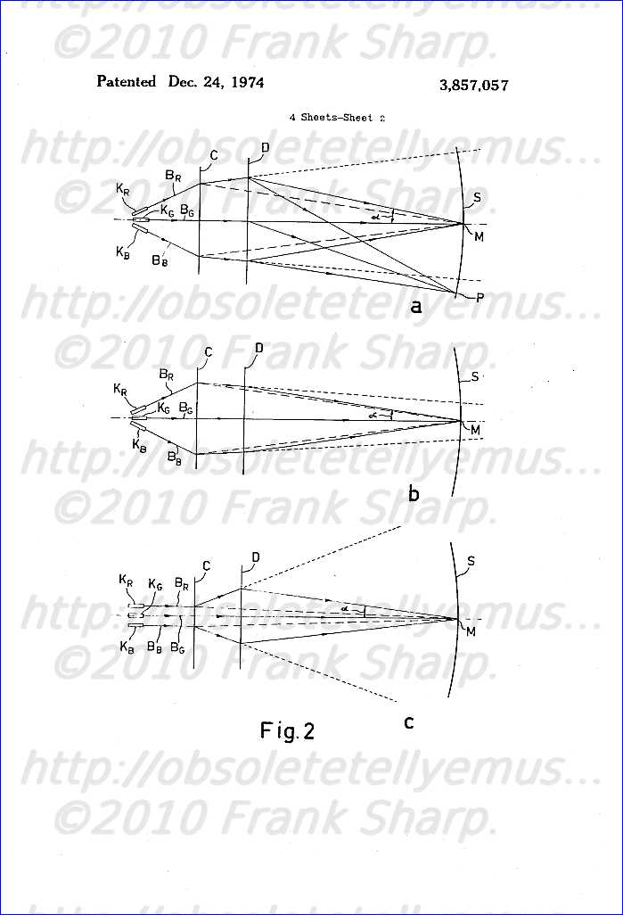 nd blue, respectively, are generated by the three cathodes K R , K G and K B and they are modulated in known manner by the colour signals R, G and B. Tube 6 also includes other electrodes which will be left out of consideration for the sake of simplicity. Cathodes K R , K G and K B are arranged in one horizontal plane, in which beam B G substantially coincides with the axis of tube 6 while beams B R and B B are generated in a diverging manner relative thereto. Corrector 16 consists of, for example, four electromagnets 16 RV , 16 BV and 16 RH , 16 BH (not shown) which are substantially located in the same plane as the beams and whose influence is approximately felt in a plane C which is at right angles to the plane of FIG. 2a, in which electromagnets 16 RV and 16 BV ensure the vertical convergence of the "red" and "blue" beams, respectively, while electromagnets 16 RH and 16 BH ensure the horizontal convergence thereof. Corrector 16 envisages a pre-correction of the direction of the beams which can be realized by adjusting the direct currents flowing through the said electromagnets. Beams B R and B B are deflected in the plane C but remain in the horizontal plane. In addition they continue to diverge while beam B G is substantially not influenced.
Without further steps beams B R and B B would continue to diverge in the absence of the deflection currents after passing deflection plane D as is shown in broken lines in FIG. 2a. Beam B G impinges upon display screen S in the centre M thereof. In the presence of the deflection currents flowing through coil system 12 the beams are horizontally and vertically deflected. Beam B G impinges upon screen S at a point P. It is clear that in both cases beams B R and B B will not impinge upon screen S at the same point as beam B G .
FIG. 3 shows an elevational view at right angles to the axis of tube 6 of the magnetic core 19 of deflection coil system
 12 in a direction opposite to the propagation direction of the electron beams B R , B G and B B in which the deflection coils themselves have not been shown for the sake of simplicity. Four windings 20, 21, 22 and 23 are toroidally wound on core 19 which are arranged, for example, in series and through which a direct current i provided by direct current source 18 flows. Windings 21 and 23 are provided at the area where the X-axis and core 19 cross each other, which X-axis coincides with the horizontal deflection direction, while windings 20 and 22 are provided at the area where the Y-axis and core 19 cross each other, which Y-axis coincides with the vertical deflection direction. Windings 20, 21, 22 and 23 have substantially the same number of turns and consequently generate four substantially identical magnetic fields some lines of force of which are shown by arrows in FIG. 3. The winding sense of the windings is chosen to be such that the said fields in core 19 counteract each other. Under these circumstances the resultant field can be considered as a quadripolar field whose poles are located approximately in the direction of the diagonals U and V of the X-Y-system of axes. It will be evident that other embodiments are possible for which windings 20, 21, 22 and 23 are not identical and/or through which not the same current flows, provided that the fields generated by these windings result in a quadripolar field as described.
FIG. 3 clearly shows that the quadripolar field in the absence of the deflection field does not exert influence on beam B G which, in fact, is located in the centre of plane D. Beams B B and B R undergo a force directed along the X-axis, which force attempts to bring these beams nearer to each other. Deflection coil system 12 therefore has a converging action. In the presence of the deflection field an influence of beam B G is felt, but this converging action remains.
For a given design of the display tube and of the deflection coil system a fixed direct current through windings 20, 21, 22 and 23 may be chosen for a satisfactorily converged image. The convergence is to be further adjusted by means of corrector 16. For this purpose the currents flowing through electromagnets 16 RV , 16 RH , 16 BV and 16 BH of corrector 16 may be separately adjustable. As a result deviations in the landings of the beams as a result of tolerances of the guns may be largely obviated. Under these circumstances it can be ensured that the three beams impinge at points M and P of display screen S.
FIG. 2b shows the same as FIG. 2a, however, with the difference that beams B R and B B do not diverge after passing plane C, but converge on the understanding, however, that in the absence of the described quadripolar field they would intersect each other beyond the display screen. The advantage of the step according to the invention is then maintained. The same applies when the cathodes are not arranged in a diverging manner but are arranged parallel to each other and to the axis of tube 6. in the latter case, likewise as in the case of FIGS. 2a and 2b, angle α, the colour selection angle, is still larger than in the case where the beams would leave plane C in a converging manner towards a point located within tube 6. In FIG. 2 chain-link lines denote the beams in the known case where the convergence is exclusively effected in plane C.
FIG. 2c shows the situation in which the cathodes run parallel and in which beams B R and B B leave plane C in a diverging manner. In this manner they reach plane D still at a greater distance from the axis than in the known arrangements, in other words, colour selection angle α is enlarged. Since the thickness of the neck of the tube is determined by the largest distance in plane C from the extreme beams, in this case B R and B B , the situation according to FIG. 2c has the advantage that the neck can be made still narrower. As a result both the deflection field and the quadripolar field according to the invention can exert more influence on the beams.
It may be noted that the construction of the guns may be of such a good quality that in the embodiments according to FIGS. 2a and 2b no or substantially no current need be applied to corrector 16. In such a case the quadripolar field according to the invention exclusively or substantially exclusively ensures the convergence of the beams.
It may be concluded from FIG. 3 that the same converging effect may be obtained with the aid of windings 21 and 23 only. This is not true. In fact, the magnetic fields induced in core 19 by windings 21 and 23 would circulate in the core in the absence of windings 20 and 22 without being able to exert a noticeable influence in the space within the core.
The same converging action in deflection plane D may alternatively be realized with the aid of the saddle coils 20', 21', 22', and 23' of FIG. 4 which coils are provided substantially symmetrically about diagonals UU and V. FIG. 4 shows that the lines of force of the quadripolar field generated by these coils have the desired direction in the space within core 19 and close within the core. Alternatively, windings 20, 21, 22 and 23 of FIG. 3 may be replaced by four permanent magnets having pole shoes and being provided on the inner side of core 19 at the area where the X and Y-axis cross the core, the magnetisation of the magnets being tangentially directed. In the same manner windings 20', 21', 22' and 23' of FIG. 4 may be replaced by four permanent magnets having pole shoes and being provided on the inner side of core 19 at the area where diagonals U and V cross the core with the magnetisation of the magnets being radially directed.
In the embodiments already described the deflection coils may be formed arbitrarily, that is to say, it is of no importance for the invention whether they are toroidally wound or are wound as saddle coils. However, in the case where the deflection coils are wound toroidally on core 19 they can generate the required quadripolar field according to one aspect of the invention without the necessity of providing an extra winding on the core. For this purpose each deflection coil must be split up into two coil halves which coil halves are to be arranged on core 19 in the same manner as windings 20, 21, 22 and 23 of FIG. 3. A possible embodiment of this principle is shown in a very diagrammatical way in FIG. 5. In this case windings 20 and 22 are the coil halves for the vertical deflec
 tion and are arranged in parallel. In a similar manner windings 21 and 23 are likewise arranged in parallel and are the coil halves for the horizontal deflection. The deflection generators 8 and 9 of FIG. 1 provide the line deflection current i H and the field deflection current i V , respectively. Direct voltage sources 18' and 18" are arranged in series with a coil half, for example, coil halves 21 and 22, respectively. The direct currents i' and i" provided by sources 18' and 18", respectively, are added to deflection currents i H and i V in one coil half, for example, 21 and 20, respectively, while currents i' and i" in the other coil halves 23 and 22 are subtracted from deflection currents i H and i V , respectively. When sources 18' and 18" are proportioned in such a manner that the fields generated by currents i' and i" are substantially equal, coil halves 20, 21, 22 and 23 generate the desired quadripolar field. It will be noted that deflection generators 8 and 9 also provide direct currents for centring the displayed image on screen S. These direct currents are, however, identical for the relevant deflection coil halves 20, 22 and 21, 23 and consequently do not generate a quadripolar field.
In the case where a dynamic correction of the convergence is necessary, it can be performed with the aid of a quadripolar field generated by windings 20, 21, 22 and 23 of FIG. 3 and 5 or windings 20', 21', 22' and 23' of FIG. 4. A line and/or field frequency sawtooth current which is adjustable, if necessary, may be superimposed, for example, on the current provided by the source 18, and sources 18' and 18".
Due to the step according to the invention the colour selection angle is enlarged without the necessity of thickening the cross-section of the neck of the display tube. It may even become narrower. This is an advantage which will now be described in detail.
FIG. 6 shows an enlarged part of FIG. 2 in the vicinity of display screen S in which a shadow mask is denoted by m 1 . Line B R1 denotes the "red" electron beam for known arrangements, line B R2 shows the same beam for the arrangement according to the invention. Beam B G passes through a hole in mask m 1 and impinges upon screen S at a point M G in its centre in which a green luminescing phosphor dot is provided, while beam B R1 passes through a hole in mask m 1 and impinges upon screen S at a point M R in which a red luminescing phosphor dot is provided. Since beam B R2 lands under a larger angle than beam B R1 , it impinges upon screen S at the same point M R if the shadow mask in m 2 is placed nearer to screen S. As a result the landing, that is to say, the colour purity is less sensitive to magnetic interference fields as will now be described. Such fields are generated, for example, by transformers which are present in the television display apparatus or by the earth magnetism field. It is true that the display tube is somewhat screened from such fields but nevertheless they exert a given influence within the tube. As a result the beams of FIG. 6 do not land under the angles shown but under angles which deviate to a slight extent. The landing error then occurring is approximately proportional to the deviation of the angle of the relevant beam caused by the interference fields and to the distance between the shadow mask and the screen. The same applies to the landing errors which may be caused by deviations in the geometry of the different components of the display tube and/or in the position of the deflection plane D with the landing being effected under an angle which deviates to a slight extent. For these reasons it is advantageous to place the mask nearer to the screen.
Although in the foregoing a display tube in which the electron beams are substantially generated in one horizontal plane has been referred to, it will be evident that the invention may alternatively be used if the generating device of the beams is located in a differently directed plane, for example, a vertical plane. A display tube employing three cathodes has also been referred to. The invention is, however, also usable for, for example, multi-beam cathode ray tubes employing one cathode and also for tubes other than those of the shadow mask type.
Pairs of oppositely rotatable ring magnets for a color television display device
PHILIPS 20AX SYSTEM INLINE CRT TUBE.
A display device for colour television, comprising a correction device which is to be connected on the neck of a display tube and which comprises two pairs of diametrically magnetized rings in order to enable separate displacement of the electron beams in the tube in the horizontal and in the vertical direction.
1. A display device for colour television, comprising a display tube having a cylindrical neck portion in which three electron guns are adjacently arranged in one plane, and a flared portion, comprising a colour selection electrode and a display screen, the neck portion having provided thereon a correction device comprising a first pair of permanently, diametrically magnetized rings which are rotatable about the tube axis, characterized in that the correction device (13) comprises a second pair (21) of permanently, diametrically magnetized rings which are rotatable about the axis of the tube (1, 3), the fixation of the rings allowing only a rotation of the rings of each pair (19, 21) in opposite directions and through identical angles, the arrangement being such that the resultant magnetic field (H19) of the first ring pair (19) is always perpendicular to the plane of the electron guns (5), the resultant magnetic field (H21) of the second pair (21) always being parallel to this plane. 2. A correction device for a display device as claimed in claim 1, characterized in that the two ring pairs (19, 21) are secured to a common support (29), comprising means for rigidly connecting the correction device (13) to the neck (1) of the tube.
Description:
The invention relates to a display device for colour television, comprising a display tube having a cylindrical neck portion in which three electron guns are adjacently arranged in one plane, and a flared portion, comprising a colour selection electrode and a display screen, the neck portion having provided thereon a correction device comprising a first pair of permanently, diametrically magnetized rings which are rotatable about the tube axis.
A display device of this kind is known, for example, from U.S. Pat. No. 3,725,831. The diametrically magnetized rings serve for the displacement, simultaneously and in the same direction, of the three electron beams generated by the electron guns, so that each of the beams is incident on the display screen only at areas where a phosphor is situated which luminesces in the colour associated with the relevant beam (colour purity adjustment). Because the phosphors on the display screen of a display tube comprising three electron guns which are situated in one plane (usually the horizontal plane) are usually provided in interrupted or non-interrupted stripes perpendicular to the plane of the electron guns (i.e. vertically extending), it is sufficient for the colour purity adjustment per se to displace the electron beams perpendicular to the course of the phosphor stripes, i.e. in the horizontal direction. However, it was found that a deviation of the beams in the vertical direction causes a completely different error, which becomes significant when a pattern comprising horizontal lines is displayed by the display device. In that case the horizontal lines displayed appear to be curved. This curvature can be eliminated by displacing the electron beams together in the vertical direction. It is theoretically possible to realize all combinations of horizontal and vertical displacements using two diametrically magnetized rings. However, it was found in practice that mutual influencing of the two corrections makes it very difficult to perform the two corrections satisfactorily within a reasonable period of time. Therefore, the correction is generally limited to the colour purity, and the correction of the curved horizontal line is omitted.
The invention has for its object to provide a device in which the two corrections can be simply and quickly performed, independently of each other. To this end, the device according to the invention is characterized in that the correction device comprises a second pair of permanently, diametrically magnetized rings which are rotatable about the tube axis, the fixation of the rings allowing only a rotation of the rings of each pair in opposite directions and through identical angles, the arrangement being such that the resultant magnetic field of the first ring pair is always perpendicular to the plane of the electron guns, the resultant magnetic field of the second pair always being parallel to this plane.
The first ring pair then exclusively serves for the adjustment of the colour purity, and the second pair for straightening the curved horizontal line.
The invention will be described in detail hereinafter with reference to the drawing.
FIG. 1 shows a simplified side elevation of a display device according to the invention.
FIGS. 2a and b diagrammatically illustrate the operation of the device according to the invention, and
FIG. 3 shows a section at an increased scale taken along the line III--III of the device shown in FIG. 1.
The colour television display device shown in FIG. 1 comprises a display tube, consisting of a cylindrical neck portion 1 and a flared front portion 3. The neck portion comprises three adjacent electron guns 5 (denoted by broken lines) which are situated in a horizontal plane (perpendicular to the plane of the drawing), whilst the flared portion 3 comprises a colour selection electrode (shadow-mask) 7 and a display screen 9 (also denoted by broken lines). At the area of the transition between the two tube portions a known deflection device 11 is provided about the tube, a correction device 13 being provided therebehind on the tube neck 1. This correction device comprises a pair of convergence rings 15 with permanent four-pole magnetization, a pair of convergence rings 17 with permanent six-pole magnetization, and a first pair of permanently, diametrically magnetized rings 19 (two-pole magnetization) for adjusting the colour purity as described in the said U.S. Pat. No. 3,725,831.
According to the invention, the correction device comprises a second pair of rings 21 with two-pole magnetization which serves for the correction of vertical deviations of the electron beams combined. The resultant magnetic field of the first pair of two-pole rings 19 is always vertically directed, and that of the second pair 21 is always horizontally directed.
This is diagrammatically illustrated in FIGS. 2a and b, in which each time the position of the four poles of a pair of rings is shown with respect to the electron beams 23, 25, 27 generated by the electron guns. FIG. 2a shows that for the ring pair 19 the two north poles N (shown in one plane and on the same circle for the sake of simplicity, even though in reality they are, of course, situated on two different rings) are always situated at the same angular distances α from the vertical, the one north pole being situated to the left and the other north pole being situated to the right of the vertical. The resultant H 19 of the two magnetic field strengths H 19 ' and H 19 " generated by the rings is then also vertically directed, the angle α determining the value of H 19 . This vertical field strength causes a horizontal displacement of the electron beams 23, 25, 27 which is equally large for all beams because the field within the ring pair 19 is substantially homogeneous.
FIG. 2b shows the second ring pair 21, in which the two north poles N enclose equal and opposed angles β with the horizontal, so that the field strength H 21 resulting from the two field strengths H 21 ' and H 21 " is horizontally directed and is dependent only of β as far as its value is concerned. As a result, an equal, vertical displacement of the three electron beams 23, 25, 27 is realized.
FIG. 3 is a cross-sectional view, taken along the line III--III of FIG. 1, of a feasible structural solution for the fixation of the rings of a pair such that the said conditions are satisfied. Connected on the tube neck, using means which are known per se (not shown), is a support 29 which is common to all ring pairs 15, 17, 19, 21, and on which a holder 31 is slid, comprising a recess 33 in which a cam 35 of the support engages so that the holder cannot be rotated with respect to the support and the tube neck. The holder 31 is provided with an annular centring edge 37 with an interruption in which a pinion 41, rotatable about a shaft 39, is situated.
Present within the centring edge 37 is a first diametrically magnetized ring 43 having exterior teeth 45, and situated outside the centring edge is a second diametrically magnetized ring 47 having interior teeth 49. The teeth 45 and 49 engage the pinion 41, with the result that a rotation of the outer ring 47 automatically causes a rotation of the inner ring 43 through the same angle, be it that the latter rotation is in the opposite direction. This construction is described in detail in the previous Netherlands Pat. Application No. 73,04,887 in the name of applicant. So as to facilitate the rotation of the outer ring 47, it is provided with four radial projections 51, one of which is provided with a notch 53 to indicate the location of the north pole N. Mounting is preferably effected such that the north poles N of the two rings 43, 47 are situated directly over the central electron beam 25 when the notch 53 is situated directly over this beam. The other diametrically magnetized ring pair 21 is similarly constructed, be it that the two north poles N are situated in the plane of the three electron beams 23, 25, 27 when they coincide.
Besides the described construction, there are a variety of other possibilities of satisfying the requirements imposed as regards the movement of the two rings, for example, the arrangement of the rings one behind the other with an intermediate pinion, or the coupling of the movement of the rings by means of a belt.
A display device of this kind is known, for example, from U.S. Pat. No. 3,725,831. The diametrically magnetized rings serve for the displacement, simultaneously and in the same direction, of the three electron beams generated by the electron guns, so that each of the beams is incident on the display screen only at areas where a phosphor is situated which luminesces in the colour associated with the relevant beam (colour purity adjustment). Because the phosphors on the display screen of a display tube comprising three electron guns which are situated in one plane (usually the horizontal plane) are usually provided in interrupted or non-interrupted stripes perpendicular to the plane of the electron guns (i.e. vertically extending), it is sufficient for the colour purity adjustment per se to displace the electron beams perpendicular to the course of the phosphor stripes, i.e. in the horizontal direction. However, it was found that a deviation of the beams in the vertical direction causes a completely different error, which becomes significant when a pattern comprising horizontal lines is displayed by the display device. In that case the horizontal lines displayed appear to be curved. This curvature can be eliminated by displacing the electron beams together in the vertical direction. It is theoretically possible to realize all combinations of horizontal and vertical displacements using two diametrically magnetized rings. However, it was found in practice that mutual influencing of the two corrections makes it very difficult to perform the two corrections satisfactorily within a reasonable period of time. Therefore, the correction is generally limited to the colour purity, and the correction of the curved horizontal line is omitted.
The invention has for its object to provide a device in which the two corrections can be simply and quickly performed, independently of each other. To this end, the device according to the invention is characterized in that the correction device comprises a second pair of permanently, diametrically magnetized rings which are rotatable about the tube axis, the fixation of the rings allowing only a rotation of the rings of each pair in opposite directions and through identical angles, the arrangement being such that the resultant magnetic field of the first ring pair is always perpendicular to the plane of the electron guns, the resultant magnetic field of the second pair always being parallel to this plane.
The first ring pair then exclusively serves for the adjustment of the colour purity, and the second pair for straightening the curved horizontal line.
The invention will be described in detail hereinafter with reference to the drawing.
FIG. 1 shows a simplified side elevation of a display device according to the invention.
FIGS. 2a and b diagrammatically illustrate the operation of the device according to the invention, and
FIG. 3 shows a section at an increased scale taken along the line III--III of the device shown in FIG. 1.
The colour television display device shown in FIG. 1 comprises a display tube, consisting of a cylindrical neck portion 1 and a flared front portion 3. The neck portion comprises three adjacent electron guns 5 (denoted by broken lines) which are situated in a horizontal plane (perpendicular to the plane of the drawing), whilst the flared portion 3 comprises a colour selection electrode (shadow-mask) 7 and a display screen 9 (also denoted by broken lines). At the area of the transition between the two tube portions a known deflection device 11 is provided about the tube, a correction device 13 being provided therebehind on the tube neck 1. This correction device comprises a pair of convergence rings 15 with permanent four-pole magnetization, a pair of convergence rings 17 with permanent six-pole magnetization, and a first pair of permanently, diametrically magnetized rings 19 (two-pole magnetization) for adjusting the colour purity as described in the said U.S. Pat. No. 3,725,831.
According to the invention, the correction device comprises a second pair of rings 21 with two-pole magnetization which serves for the correction of vertical deviations of the electron beams combined. The resultant magnetic field of the first pair of two-pole rings 19 is always vertically
 directed, and that of the second pair 21 is always horizontally directed.
This is diagrammatically illustrated in FIGS. 2a and b, in which each time the position of the four poles of a pair of rings is shown with respect to the electron beams 23, 25, 27 generated by the electron guns. FIG. 2a shows that for the ring pair 19 the two north poles N (shown in one plane and on the same circle for the sake of simplicity, even though in reality they are, of course, situated on two different rings) are always situated at the same angular distances α from the vertical, the one north pole being situated to the left and the other north pole being situated to the right of the vertical. The resultant H 19 of the two magnetic field strengths H 19 ' and H 19 " generated by the rings is then also vertically directed, the angle α determining the value of H 19 . This vertical field strength causes a horizontal displacement of the electron beams 23, 25, 27 which is equally large for all beams because the field within the ring pair 19 is substantially homogeneous.
FIG. 2b shows the second ring pair 21, in which the two north poles N enclose equal and opposed angles β with the horizontal, so that the field strength H 21 resulting from the two field strengths H 21 ' and H 21 " is horizontally directed and is dependent only of β as far as its value is concerned. As a result, an equal, vertical displacement of the three electron beams 23, 25, 27 is realized.
FIG. 3 is a cross-sectional view, taken along the line III--III of FIG. 1, of a feasible structural solution for the fixation of the rings of a pair such that the said conditions are satisfied. Connected on the tube neck, using means which are known per se (not shown), is a support 29 which is common to all ring pairs 15, 17, 19, 21, and on which a holder 31 is slid, comprising a recess 33 in which a cam 35 of the support engages so that the holder cannot be rotated with respect to the support and the tube neck. The holder 31 is provided with an annular centring edge 37 with an interruption in which a pinion 41, rotatable about a shaft 39, is situated.
Present within the centring edge 37 is a first diametrically magnetized ring 43 having exterior teeth 45, and situated outside the centring edge is a second diametrically magnetized ring 47 having interior teeth 49. The teeth 45 and 49 engage the pinion 41, with the result that a rotation of the outer ring 47 automatically causes a rotation of the inner ring 43 through the same angle, be it that the latter rotation is in the opposite direction. This construction is described in detail in the previous Netherlands Pat. Application No. 73,04,887 in the name of applicant. So as to facilitate the rotation of the outer ring 47, it is provided with four radial projections 51, one of which is provided with a notch 53 to indicate the location of the north pole N. Mounting is preferably effected such that the north poles N of the two rings 43, 47 are situated directly over the central electron beam 25 when the notch 53 is situated directly over this beam. The other diametrically magnetized ring pair 21 is similarly constructed, be it that the two north poles N are situated in the plane of the three electron beams 23, 25, 27 when they coincide.
Besides the described construction, there are a variety of other possibilities of satisfying the requirements imposed as regards the movement of the two rings, for example, the arrangement of the rings one behind the other with an intermediate pinion, or the coupling of the movement of the rings by means of a belt.
Magnetic correction device for a cathode ray tube:PHILIPS 20AX SYSTEM INLINE CRT TUBE COLOR PURITY NECK MAGNETS DEVICES SYSTEM.
Magnetic correction device for a cathode ray tube, which device comprises a plurality of ring pairs which are secured to supports and each consist of rings which have magnetic poles distributed about their peripheries. The two rings of each pair are concentrically mounted and preferably are interconnected by a pinion so as to be rotatable in opposite senses.
1. Magnetic correction device for influencing the paths of electron beams produced in a cathode ray tube, which device comprises at least one support made of a non-magnetic material, securing means for securing the support to the neck of a cathode ray tube, and at least one pair of coaxial rings having magnetic poles distributed about their peripheries, which rings are mounted on the support and are rotatable about their axes in opposite relative directions, characterized in that one of the two rings of a pair has an inner diameter which is greater than the outer diameter of the other ring, the smaller ring being mounted within the larger ring, whilst the outer ring has teeth on its inner periphery and the inner ring has teeth on its outer periphery, at least one pinion, which is rotatable about a spindle secured to the support and extending parallel to the axis of the ring pair, being located in the space between the two rings and meshing with the said teeth. 2. Correction device as claimed in claim 1, characterized in that the teeth on the two rings are equal in number. 3. Correction device as claimed in claim 1, characterized in that the outer ring is provided with at least one radially externally projecting lug. 4. Correction device as claimed in claim 3, characterized in that the support also is provided with at least one radial lug which projects to the exterior. 5. Correction device as claimed in claim 3, characterized in that the lugs are radially extensible by means of an extension adapted to be slipped on one of the lugs. 6. Correction device as claimed in claim 1, characterized in that the securing means for securing the support to the neck of a cathode ray tube comprise an intermediate ring which is adapted to be coaxially placed around the tube neck and to which at least one support is secured so as to be rotatable about the intermediate ring as a spindle. 7. Correction device as claimed in claim 6, characterized in that two supports are provided which are spacedly and axially rotatably secured to the intermediate ring, each of the rings carried by the first support having four magnetic poles distributed about its periphery, whilst each of the rings carried by the second support has six magnetic poles distributed about its periphery. 8. Correction device as claimed in claim 7, characterized in that between the two supports which are rotatably secured to the intermediate ring a third support is secured to the intermediate ring so as to be locked against rotation, each of the rings carried by the third support having two diametrically arranged magnetic poles. 9. Correction device as claimed in claim 6, characterized in that means are provided for locking each support against rotation about the intermediate ring after the desired correction has been effected. 10. Correction device as claimed in claim 9, characterized in that the locking means comprise knurled areas which are provided on each rotatable supports (47) and are capable of engaging a knurled area which is not rotatable relative to the intermediate ring. 11. Correction device as claimed in claim 10, characterized in that the knurled areas are located on the major surfaces of each support and the non-rotatable knurled area is located on the middle, non-rotatable support, thrust means being provided for exerting an axial force on the set of supports. 12. Correction device as claimed in claim 11, characterized in that the thrust means comprise a thrust ring which is secured to the intermediate ring and is rotatable about the intermediate ring as a spindle and the thickness of which varies in the peripheral direction at least near the inner periphery, the portion of varying thickness being located between at least one radial projection formed on the intermediate ring and one of the supports, the arrangement being such that the spacing between the projection and the said support is greater than the smallest thickness and smaller than the greatest thickness of the said portion of the thrust ring. 13. Correction device as claimed in claim 6, characterized in that a conical clamping ring is provided to secure the intermediate ring to the neck of a cathode ray tube.
Description:
The invention relates to a magnetic correction device for influencing the paths of electron beams produced in a cathode ray tube, which device comprises at least one support made of a non-magnetic material, securing means for securing the support on the neck of a cathode ray tube, and at least one pair of coaxial rings having magnetic poles distributed about their peripheries, which rings are mounted on the support and are rotatable about their axes in opposite relative directions.
Such correction devices are used, for example, in colour television display tubes for correcting the paths of the electron beams so that firstly each beam impinges on only that part of a phosphor pattern provided on the display screen of the tube which luminesces in the correct colour (colour purity) and secondly the three beams intersect at the correct location (convergence). Such a device is described, for example, in re-issued U.S. Pat. No. Re. 27,209. A present trend in the design of television receivers is to reduce the receiver depth to a minimum. This depth is substantially exclusively determined by the length of the display tube, one of the factors which govern this length being the axial dimensions of the correction device. Hence it is desirable for this dimension to be as small as possible.
It is an object of the present invention to provide a construction which satisfies this requirement. For this purpose the device according to the invention is characterized in that one of the two rings of a pair has an inner diameter which is greater than the outer diameter of the other ring, the smaller ring being mounted within the larger ring, whilst the outer ring has teeth on its inner periphery and the inner ring has teeth on its outer periphery, at least one pinion which is rotatable about a spindle secured to the support and extending parallel to the axis of the ring pair being located in the space between the two rings and meshing with the said teeth. Preferably the two rings have equal numbers of teeth, causing them to rotate through equal and opposite angles.
For the purpose of corrective adjustment the rings and/or the support preferably have lugs which radially project to the exterior.
An embodiment which enables the correction device to be readily mounted on the tube neck and the support to be readily rotated for adjusting the desired correction is characterized in that the securing means for securing the support on the neck of a cathode ray tube comprise an intermediate ring which is adapted to be coaxially mounted on the tube neck and to which at least one support is secured so as to be rotatable about the intermediate ring as a spindle.
An embodiment of the invention will now be described by way of example with reference to the accompanying diagrammatic drawings, in which:
FIG. 1 is a schematic side elevation of a cathode ray tube provided with a correction device according to the invention,
FIGS. 2a to 2c illustrate the corrections to be effected by means of the correction device according to the invention,
FIG. 3 is a front elevation of a support which carries a pair of rings and forms part of the correction device according to the invention,
FIG. 4 is a longitudinal sectional view of the support and the ring pair shown in FIG. 3,
FIG. 5 is an exploded perspective view of the correction device according to the invention,
FIG. 6 is a side elevation of the correction device shown in FIG. 5,
FIG. 7 is a developed view of a portion of the thrust ring which forms part of the device shown in FIGS. 5 and 6, and
FIGS. 8a and 8b are a longitudinal sectional view and a cross-sectional view respectively of an extension for use with the device shown in FIGS. 5 and 6.
Referring now to FIG. 1, there is schematically shown a cathode ray tube which comprises a cylindrical neck 1 and a flaring part 3 which at the front carries a display screen 5. The neck contains three electron guns 7 which are arranged side by side, only one of them being shown (in broken lines), and are capable of producing three electron beams which extend side by side in a horizontal plane. A known deflection system 9 is provided for deflecting the said electron beams so that they scan the entire display screen 5, which system surrounds the tube at the junction of the neck 1 and the flaring part 3. A magnetic correcting device 11 is mounted on the tube neck for correcting directional errors of the three electron beams produced by the electron guns 7. The corrections to be performed by means of such a device are illustrated in FIGS. 2a to 2c. In these Figures the three electron beams are designated 13, 15 and 17 respectively. The display screen 5 is provided with a pattern of vertical stripes of phosphor which when struck by an electron beam luminesce in one of the colours red, green and blue (not shown). A colour selection electrode (shadow mask) 19 (shown in broken lines in FIG. 1) serves to ensure that each electron beam can impinge on phosphor stripes of one colour only. The beam 13 is to strike the red phosphor, the beam 15 the green phosphor, and the beam 17 the blue phosphor. Owing to inevitable inaccuracies in manufacturing the tube and the deflection system deviations from the ideal situation are found to occur in practice. These deviations will be readily apparent when a grid of horizontal and vertical white lines is displayed on the display screen 5. In actual fact such a grid comprises three exactly registering grids of red, green and blue lines respectively. The first error which may occur consists in that the electron beams do not always impinge on the phosphor stripes of the correct colour only, i.e. part of, for example, the green beam may strike the green phosphor and part may strike the red phosphor. This error can be corrected by shifting the beams in a horizontal direction, for example by producing a magnetic field the lines of force of which extend in the vertical direction at the location of the beams, i.e. centrally of the tube neck 1. This may be effected, for example in the manner shown in FIG. 2a, by means of a magnetic ring 21 having two diametrically opposed magnetic poles. Magnetic lines of force 23 cause horizontal shifting of the beam 15 (and also of the beams 13 and 17) in the direction indicated by arrows 25. The strength of the magnetic field and hence the magnitude of the shift 25 can be rendered controllable by rotating two rings 21 in opposite directions (this step is known). Rotation of both rings through 180° enables the shift to be varied from extreme right via zero to extreme left. This correction is referred to as colour purity correction.
A second possible error is that the three grids (which after the colour purity correction each have the correct colour) are not in register. This error (convergence error) can be corrected in two steps. First (see FIG. 2b) the red and blue grids are made to register by shifting the beams 13 and 17 in opposite directions. For this purpose a quadrupolar magnetic field is produced (in known manner) by means of a magnetic ring 27 which has four poles distributed about its periphery. At the locations of the beams 13 and 17 lines of force 29 of the magnetic field produced by the ring 27 always extend in opposite directions so that shifts 31 and 33 of said beams also have opposite directions. The strength of the quadrupolar field can be controlled, in the same manner as that of the bipolar field of the colour purity ring 21, by rotating two rings 27 in opposite directions. The directions of the shifts 21 and 33 can be controlled by jointly rotating the two rings 27 in the same direction. FIG. 2b shows further that the ring 27 does not produce a magnetic field at the location of the middle beam 15 and hence this beam is not influenced.
After the red and blue grids have been superimposed on one another in the manner described, the resulting combined grid must be brought into register with the green grid. For this purpose the beams 13 and 17 are to be shifted in the same direction through equal distances, as is shown in FIG. 2c. This can be obtained by means of a sextupolar magnetic field which is produced by a magnetic ring 35 having six magnetic poles distributed about its periphery. As FIG. 2c shows, magnetic lines of force 37 then have the same direction at the locations of the beams 13 and 17, so that the shifts 39 and 41 respectively of these beams are identical. In complete analogy with the situation illustrated by FIG. 2b the magnitude and the direction of the shifts are adjustable by rotating the two rings 35 first in opposite senses and then in the same sense. In this case also, the resulting magnetic field strength at the location of the green beam 15 is zero.
From the above it will be obvious that for each possibility of correction a pair of rings having magnetic poles distributed about their peripheries are required which are to be rotatable in opposite senses and, in many cases, jointly in the same sense also. To enable the axial length of the correction device 11 yet to be reduced to a minimum pairs of rings 43, 45 are designed so that one of the rings (43) has an inner diameter which is greater than the outer diameter of the other ring (45). As FIGS. 3 and 4 show, the smaller ring 45 is mounted concentrically within the larger ring 43. The two rings 43 and 45 are disposed on a likewise ring-shaped support 47 which can be mounted on the tube neck so as to be rotatable together with the ring pair about the axis of the tube. The support 47 has a protruding rim 48 along its inner circumference for the purpose of centering the ring pair. In order to enable the two rings 43 and 45 to be rotated in opposite directions also, preferably the outer ring 43 is provided with teeth 49 along its inner periphery whilst the inner ring 45 is provided with teeth 51 along its outer periphery. In the space between the two rings 43 and 45 a pinion 53 is mounted which meshes with both sets of teeth 49 and 51. The pinion 53 is arranged to revolve about a spindle 55 formed on the support 47 and extending parallel to the axis of the ring pair. In order to drive the two rings 43 and 45 the outer ring 43 only has to be rotated, the inner ring 45 then being automatically rotated in the opposite sense. For this purpose the outer ring 43 is provided with radially projecting lugs 57, four in the present embodiment. Adjustment of the magnetic field strength will be easiest if the two rings 43 and 45 always rotate in opposite senses through equal angles. This is obtained by using equal numbers of teeth 49 and 51. If desired, two or more pinions 53 may be used which may be distributed about the space between the two rings 43 and 45. In order to facilitate rotation of the support 47 this also is provided with a number of radially pro
 jecting lugs 59 (one in the present case).
A correction device comprising three supports 47 each carrying a ring pair 43, 45 is shown in an exploded perspective view in FIG. 5 and in side elevation in FIG. 6. The three supports 47 are secured one behind the other to an intermediate ring 61 having an inner diameter such as to fit around the tube neck with a small amount of clearance. In order to enable the intermediate ring 61 to be clamped to the tube neck its inner diameter increases towards one end (the righthand end in FIG. 5; this increase is not visible in the drawings), a conical clamping ring 63 fitting within this end. The conical clamping rings 63 has a gap 64 which progressively closes as the ring is axially thrust into the flaring part of the intermediate ring 63. As a result the diameter of the conical clamping ring 63 is decreased so that it firmly encloses the tube neck. To increase the friction between clamping ring 63 and the glass of the tube neck 1 the ring is internally provided with rubber strips 65. To enable axial pressure to be exerted on the clamping ring 63 a ring 67 is provided which by means of radial inward projections 69 engages behind a collar 71 formed on the intermediate ring 61 and has inclined rim sections 73 which cooperate with inclined rim sections 75 of the conical clamping ring 63, so that rotation of the ring 67 results in axial displacement of the clamping ring 63. To facilitate rotation of the ring 67 it is provided with a radially protruding lug 77.
The outer diameter of the intermediate ring 61 is such that it fits with a small amount of clearance in the support 47 and hence can be used as a spindle for rotation of the supports. As has been set out with reference to FIG. 2a, the colour purity correction may in some cases be effected by causing two diametrically magnetised rings to revolve in opposite senses without the need for joint rotation. In this case the support 47 for the colour purity rings may be locked against rotation about the intermediate ring, which may have advantages, as will be set forth hereinafter. For efficient manufacture of the support 47 it is desirable to use supports of a single type only which are capable of being mounted on the intermediate ring 61 so as to be either rotatable or locked. For this purpose the protruding rim 48 along the inner periphery of the support 47 is formed with one or more gaps 79, a corresponding number of projections 81 being formed on the intermediate ring 61. When a support 47 is placed on the intermediate ring 61 so that a projection 81 is received in a gap 79, the support is locked against rotation. The supports 47 which are mounted in front of or behind the projections 81 are freely rotatable. In the embodiment shown in FIGS. 5 and 6 the middle support 47 (which carries diametrically magnetised rings 43 and 45) is locked and is flanked on either side by a rotatable support. One of these rotatable supports carries rings 43 and 45 which each have four magnetic poles distributed about their peripheries for effecting the correction described with reference to FIG. 2b, the other rotatable support carrying rings which each have six poles distributed about their peripheries for performing the correction described with reference to FIG. 2c. Because the locked support is interposed between the two rotatable supports, rotation of one of the rotatable supports is prevented from being transmitted to the other by friction.
Thus the rotary movements of the rotatable supports are entirely independent of one another. To prevent a corrected condition from being incidentally upset, preferably means are provided to lock the supports and possibly the rings against further rotation around the intermediate ring. For this purpose each support 47 is provided on its major surfaces with knurled areas 83 located on raised portions which also serve to center the outer ring 43. When the set of supports 47 is axially compressed, the said knurled areas ensure mutual locking. Because the middle support is locked against rotation by the projection 81, the outer supports also are locked against rotation. Axial compression of the set of supports is performed by means of a thrust ring 85 mounted for rotation around the intermediate ring 61. This thrust ring near its inner periphery has a portion 87 the thickness of which varies the peripheral direction. FIG. 7 shows the developed portion 87. This portion is located between a radial projection 89 formed on the intermediate ring 61 and the left-hand support 47. The various component parts are proportioned so that the projection 89 and the left-hand support 47 are spaced from one another by a distance intermediate between the smallest thickness x and the largest thickness y of the portion 87 of the thrust ring 85. Thus on rotation of the thrust ring 85 the portion 87 acts as a wedge which axially clamps the central supports. To facilitate the said rotation the thrust ring 85 is provided with radially projecting lugs 91. To prevent undue rotation of the thrust ring 85 the portion 87 has a knurled surface 92. In the embodiment shown the support 47 only can be locked against rotation. Obviously the rings 43 and/or 45 may also be provided with knurled areas which can engage corresponding knurled areas on the support 47, enabling the said rings also to be locked. Other locking means may be used, for example a braking block adapted to be forced against the rims of the supports 47 and the outer rings 43, which block and which rims may also be knurled.
When the lugs 57 and 59 of the rings 43 and the support 47 respectively are in substantially equal angular positions, it may be difficult to move one lug by hand without unintentionally moving the other. Hence the said lugs preferably are adapted to be axially extended for example by means of a simple extension 93 which is shown in FIG. 8 and comprises a cavity 95 adapted to be slipped onto the lugs 57, 59 and a handle 97.
In the embodiment described the correction device comprises three supports carrying ring pairs for effecting the corrections described with reference to FIG. 2. Obviously, if desired, a higher or lower number of supports may be used and furthermore the number of magnetic poles of each ring and their distribution about the periphery of each ring may be matched to the respective requirements. Thus, the correction device according to the invention is suitable for solving many different correction problems, also in cathode ray tubes of types different from that shown in FIG. 1 having three electron guns arranged side by side.
For manufacturing the correction device, as far as possible material of low magnetic permeability, for example a synthetic material, is used to prevent the stray field at the rear of the deflection system 9 from influencing the electron beams via the correction device. This also applies to the rings 43, 45, which may be made of a low-permeability magnetic material, as is the case in the embodiment described, or of a synthetic material, in which case magnets of locally secured to them, for example by means of an adhesive.
Such correction devices are used, for example, in colour television display tubes for correcting the paths of the electron beams so that firstly each beam impinges on only that part of a phosphor pattern provided on the display screen of the tube which luminesces in the correct colour (colour purity) and secondly the three beams intersect at the correct location (convergence). Such a device is described, for example, in re-issued U.S. Pat. No. Re. 27,209. A present trend in the design of television receivers is to reduce the receiver depth to a minimum. This depth is substantially exclusively determined by the length of the display tube, one of the factors which govern this length being the axial dimensions of the correction device. Hence it is desirable for this dimension to be as small as possible.
It is an object of the present invention to provide a construction which satisfies this requirement. For this purpose the device according to the invention is characterized in that one of the two rings of a pair has an inner diameter which is greater than the outer diameter of the other ring, the smaller ring being mounted within the larger ring, whilst the outer ring has teeth on its inner periphery and the inner ring has teeth on its outer periphery, at least one pinion which is rotatable about a spindle secured to the support and extending parallel to the axis of the ring pair being located in the space between the two rings and meshing with the said teeth. Preferably the two rings have equal numbers of teeth, causing them to rotate through equal and opposite angles.
For the purpose of corrective adjustment the rings and/or the support preferably have lugs which radially project to the exterior.
An embodiment which enables the correction device to be readily mounted on the tube neck and the support to be readily rotated for adjusting the desired correction is characterized in that the securing means for securing the support on the neck of a cathode ray tube comprise an intermediate ring which is adapted to be coaxially mounted on the tube neck and to which at least one support is secured so as to be rotatable about the intermediate ring as a spindle.
An embodiment of the invention will now be described by way of example with reference to the accompanying diagrammatic drawings, in which:
FIG. 1 is a schematic side elevation of a cathode ray tube provided with a correction device according to the invention,
FIGS. 2a to 2c illustrate the corrections to be effected by means of the correction device according to the invention,
FIG. 3 is a front elevation of a support which carries a pair of rings and forms part of the correction device according to the invention,
FIG. 4 is a longitudinal sectional view of the support and the ring pair shown in FIG. 3,
FIG. 5 is an exploded perspective view of the correction device according to the invention,
FIG. 6 is a side elevation of the correction device shown in FIG. 5,
FIG. 7 is a developed view of a portion of the thrust ring which forms part of the device shown in FIGS. 5 and 6, and
FIGS. 8a and 8b are a longitudinal sectional view and a cross-sectional view respectively of an extension for use with the device shown in FIGS. 5 and 6.
Referring now to FIG. 1, there
 is schematically shown a cathode ray tube which comprises a cylindrical neck 1 and a flaring part 3 which at the front carries a display screen 5. The neck contains three electron guns 7 which are arranged side by side, only one of them being shown (in broken lines), and are capable of producing three electron beams which extend side by side in a horizontal plane. A known deflection system 9 is provided for deflecting the said electron beams so that they scan the entire display screen 5, which system surrounds the tube at the junction of the neck 1 and the flaring part 3. A magnetic correcting device 11 is mounted on the tube neck for correcting directional errors of the three electron beams produced by the electron guns 7. The corrections to be performed by means of such a device are illustrated in FIGS. 2a to 2c. In these Figures the three electron beams are designated 13, 15 and 17 respectively. The display screen 5 is provided with a pattern of vertical stripes of phosphor which when struck by an electron beam luminesce in one of the colours red, green and blue (not shown). A colour selection electrode (shadow mask) 19 (shown in broken lines in FIG. 1) serves to ensure that each electron beam can impinge on phosphor stripes of one colour only. The beam 13 is to strike the red phosphor, the beam 15 the green phosphor, and the beam 17 the blue phosphor. Owing to inevitable inaccuracies in manufacturing the tube and the deflection system deviations from the ideal situation are found to occur in practice. These deviations will be readily apparent when a grid of horizontal and vertical white lines is displayed on the display screen 5. In actual fact such a grid comprises three exactly registering grids of red, green and blue lines respectively. The first error which may occur consists in that the electron beams do not always impinge on the phosphor stripes of the correct colour only, i.e. part of, for example, the green beam may strike the green phosphor and part may strike the red phosphor. This error can be corrected by shifting the beams in a horizontal direction, for example by producing a magnetic field the lines of force of which extend in the vertical direction at the location of the beams, i.e. centrally of the tube neck 1. This may be effected, for example in the manner shown in FIG. 2a, by means of a magnetic ring 21 having two diametrically opposed magnetic poles. Magnetic lines of force 23 cause horizontal shifting of the beam 15 (and also of the beams 13 and 17) in the direction indicated by arrows 25. The strength of the magnetic field and hence the magnitude of the shift 25 can be rendered controllable by rotating two rings 21 in opposite directions (this step is known). Rotation of both rings through 180° enables the shift to be varied from extreme right via zero to extreme left. This correction is referred to as colour purity correction.
A second possible error is that the three grids (which after the colour purity correction each have the correct colour) are not in register. This error (convergence error) can be corrected in two steps. First (see FIG. 2b) the red and blue grids are made to register by shifting the beams 13 and 17 in opposite directions. For this purpose a quadrupolar magnetic field is produced (in known manner) by means of a magnetic ring 27 which has four poles distributed about its periphery. At the locations of the beams 13 and 17 lines of force 29 of the magnetic field produced by the ring 27 always extend in opposite directions so that shifts 31 and 33 of said beams also have opposite directions. The strength of the quadrupolar field can be controlled, in the same manner as that of the bipolar field of the colour purity ring 21, by rotating two rings 27 in opposite directions. The directions of the shifts 21 and 33 can be controlled by jointly rotating the two rings 27 in the same direction. FIG. 2b shows further that the ring 27 does not produce a magnetic field at the location of the middle beam 15 and hence this beam is not influenced.
After the red and blue grids have been superimposed on one another in the manner described, the resulting combined grid must be brought into register with the green grid. For this purpose the beams 13 and 17 are to be shifted in the same direction through equal distances, as is shown in FIG. 2c. This can be obtained by means of a sextupolar magnetic field which is produced by a magnetic ring 35 having six magnetic poles distributed about its periphery. As FIG. 2c shows, magnetic lines of force 37 then have the same direction at the locations of the beams 13 and 17, so that the shifts 39 and 41 respectively of these beams are identical. In complete analogy with the situation illustrated by FIG. 2b the magnitude and the direction of the shifts are adjustable by rotating the two rings 35 first in opposite senses and then in the same sense. In this case also, the resulting magnetic field strength at the location of the green beam 15 is zero.
From the above it will be obvious that for each possibility of correction a pair of rings having magnetic poles distributed about their peripheries are required which are to be rotatable in opposite senses and, in many cases, jointly in the same sense also. To enable the axial length of the correction device 11 yet to be reduced to a minimum pairs of rings 43, 45 are designed so that one of the
 rings (43) has an inner diameter which is greater than the outer diameter of the other ring (45). As FIGS. 3 and 4 show, the smaller ring 45 is mounted concentrically within the larger ring 43. The two rings 43 and 45 are disposed on a likewise ring-shaped support 47 which can be mounted on the tube neck so as to be rotatable together with the ring pair about the axis of the tube. The support 47 has a protruding rim 48 along its inner circumference for the purpose of centering the ring pair. In order to enable the two rings 43 and 45 to be rotated in opposite directions also, preferably the outer ring 43 is provided with teeth 49 along its inner periphery whilst the inner ring 45 is provided with teeth 51 along its outer periphery. In the space between the two rings 43 and 45 a pinion 53 is mounted which meshes with both sets of teeth 49 and 51. The pinion 53 is arranged to revolve about a spindle 55 formed on the support 47 and extending parallel to the axis of the ring pair. In order to drive the two rings 43 and 45 the outer ring 43 only has to be rotated, the inner ring 45 then being automatically rotated in the opposite sense. For this purpose the outer ring 43 is provided with radially projecting lugs 57, four in the present embodiment. Adjustment of the magnetic field strength will be easiest if the two rings 43 and 45 always rotate in opposite senses through equal angles. This is obtained by using equal numbers of teeth 49 and 51. If desired, two or more pinions 53 may be used which may be distributed about the space between the two rings 43 and 45. In order to facilitate rotation of the support 47 this also is provided with a number of radially pro
 jecting lugs 59 (one in the present case).
A correction device comprising three supports 47 each carrying a ring pair 43, 45 is shown in an exploded perspective view in FIG. 5 and in side elevation in FIG. 6. The three supports 47 are secured one behind the other to an intermediate ring 61 having an inner diameter such as to fit around the tube neck with a small amount of clearance. In order to enable the intermediate ring 61 to be clamped to the tube neck its inner diameter increases towards one end (the righthand end in FIG. 5; this increase is not visible in the drawings), a conical clamping ring 63 fitting within this end. The conical clamping rings 63 has a gap 64 which progressively closes as the ring is axially thrust into the flaring part of the intermediate ring 63. As a result the diameter of the conical clamping ring 63 is decreased so that it firmly encloses the tube neck. To increase the friction between clamping ring 63 and the glass of the tube neck 1 the ring is internally provided with rubber strips 65. To enable axial pressure to be exerted on the clamping ring 63 a ring 67 is provided which by means of radial inward projections 69 engages behind a collar 71 formed on the intermediate ring 61 and has inclined rim sections 73 which cooperate with inclined rim sections 75 of the conical clamping ring 63, so that rotation of the ring 67 results in axial displacement of the clamping ring 63. To facilitate rotation of the ring 67 it is provided with a radially protruding lug 77.
The outer diameter of the intermediate ring 61 is such that it fits with a small amount of clearance in the support 47 and hence can be used as a spindle for rotation of the supports. As has been set out with reference to FIG. 2a, the colour purity correction may in some cases be effected by causing two diametrically magnetised rings to revolve in opposite senses without the need for joint rotation. In this case the support 47 for the colour purity rings may be locked against rotation about the intermediate ring, which may have advantages, as will be set forth hereinafter. For efficient manufacture of the support 47 it is desirable to use supports of a single type only which are capable of being mounted on the intermediate ring 61 so as to be either rotatable or locked. For this purpose the protruding rim 48 along the inner periphery of the support 47 is formed with one or more gaps 79, a corresponding number of projections 81 being formed on the intermediate ring 61. When a support 47 is placed on the intermediate ring 61 so that a projection 81 is received in a gap 79, the support is locked against rotation. The supports 47 which are mounted in front of or behind the projections 81 are freely rotatable. In the embodiment shown in FIGS. 5 and 6 the middle support 47 (which carries diametrically magnetised rings 43 and 45) is locked and is flanked on either side by a rotatable support. One of these rotatable supports carries rings 43 and 45 which each have four magnetic poles distributed about their peripheries for effecting the correction described with reference to FIG. 2b, the other rotatable support carrying rings which each have six poles distributed about their peripheries for performing the correction described with reference to FIG. 2c. Because the locked support is interposed between the two rotatable supports, rotation of one of the rotatable supports is prevented from being transmitted to the other by friction.
Thus the rotary movements of the rotatable supports are entirely independent of one another. To prevent a corrected condition from being incidentally upset, preferably means are provided to lock the supports and possibly the rings against further rotation around the intermediate ring. For this purpose each support 47 is provided on its major surfaces with knurled areas 83 located on raised portions which also serve to center the outer ring 43. When the set of supports 47 is axially compressed, the said knurled areas ensure mutual locking. Because the middle support is locked against rotation by the projection 81, the outer supports also are locked against rotation. Axial compression of the set of supports is performed by means of a thrust ring 85 mounted for rotation around the intermediate ring 61. This thrust ring near its inner periphery has a portion 87 the thickness of which varies the peripheral direction. FIG. 7 shows the developed portion 87. This portion is located between a radial projection 89 formed on the intermediate ring 61 and the left-hand support 47. The various component parts are proportioned so that the projection 89 and the left-hand support 47 are spaced from one another by a distance intermediate between the smallest thickness x and the largest thickness y of the portion 87 of the thrust ring 85. Thus on rotation of the thrust ring 85 the portion 87 acts as a wedge which axially clamps the central supports. To facilitate the said rotation the thrust ring 85 is provided with radially projecting lugs 91. To prevent undue rotation of the thrust ring 85 the portion 87 has a knurled surface 92. In the embodiment shown the support 47 only can be locked against rotation. Obviously the rings 43 and/or 45 may also be provided with knurled areas which can engage corresponding knurled areas on the support 47, enabling the said rings also to be locked. Other locking means may be used, for example a braking block adapted to be forced against the rims of the supports 47 and the outer rings 43, which block and which rims may also be knurled.
When the lugs 57 and 59 of the rings 43 and the support 47 respectively are in substantially equal angular positions, it may be difficult to move one lug by hand without unintentionally moving the other. Hence the said lugs preferably are adapted to be axially extended for example by means of a simple extension 93 which is shown in FIG. 8 and comprises a cavity 95 adapted to be slipped onto the lugs 57, 59 and a handle 97.
In the embodiment described the correction device comprises three supports carrying ring pairs for effecting the corrections described with reference to FIG. 2. Obviously, if desired, a higher or lower number of supports may be used and furthermore the number of magnetic poles of each ring and their distribution about the periphery of each ring may be matched to the respective requirements. Thus, the correction device according to the invention is suitable for solving many different correction problems, also in cathode ray tubes of types different from that shown in FIG. 1 having three electron guns arranged side by side.
For manufacturing the correction device, as far as possible material of low magnetic permeability, for example a synthetic material, is used to prevent the stray field at the rear of the deflection system 9 from influencing the electron beams via the correction device. This also applies to the rings 43, 45, which may be made of a low-permeability magnetic material, as is the case in the embodiment described, or of a synthetic material, in which case magnets of locally secured to them, for example by means of an adhesive.
GLASS FOR TELEVISION DISPLAY CATHODE-RAY TUBES:Glass for envelopes of television display cathode-ray tubes, particularly screen glass for color television, which transmits at most 0.5 mr/h of X-ray radiation at an acceleration voltage of 40 to 45 k. volt, and which has a composition in percent by weight:
what is claimed is
1. Glass for envelopes of television display cathode-ray tubes, particularly intended for the face-plate of the tube, consisting essentially of the following in percent by weight:
2. Glass as claimed in claim 1, consisting essentially of the following in percent by weight:

1. Glass for envelopes of television display cathode-ray tubes, particularly intended for the face-plate of the tube, consisting essentially of the following in percent by weight:
2. Glass as claimed in claim 1, consisting essentially of the following in percent by weight:

Description:
The invention relates to glass for an envelope of a television display cathode-ray tube, particularly glass for the face-plate of the tube.
Particular requirements are imposed on glass for envelopes of cathode-ray tubes for the display of colored television images as compared with that for the display of monochrome television images. Such special glasses are known, for example, from the British Pat. specification No. 1,123,857 the composition of which in percent by weight lies within the following range of compositions:
SiO 2 62-66 BaO 11-14 Li 2 O 0-1 MgO 0-3 Na 2 O 7-8.5 PbO 0-2 K 2 O 6.5-9 Al 2 O 3 1-4 CaO 2-4.5 As 2 O 3 + Sb 2 O 3 0.3-0.7 CeO 2 0.05-0.3
the special requirements which, as compared with glass for the envelopes for monochrome display, are imposed on glass for envelopes for color display, are connected with differences in the manufacture and in the use of these tubes. In the first place, the glass components of envelopes for color display unlike those for the monochrome display envelopes cannot be sealed by fusing them together but must be connected together with the aid of an enamel. This is connected with the fact that a shadow mask is provided in these tubes, which mask determines the path of the required three electron beams. Furthermore, an extremely fine grating-like pattern of three different luminescent substances corresponding to the apertures of the shadow mask is provided on the inner side of the screen. The requirements relative to the maximum permissible distortion of the glass are in this case much more stringent in connection therewith than for glass of envelopes for monochrome display. In addition, the temperature at which the tube must be heated during evacuation and sealing must be approximately 20° higher and the heat treatment is of a longer duration than for the tubes for monochrome display.
The glasses within the above-mentioned range are eminently satisfactory in a technological respect relative to the softening point, the quality and the thermal coefficient of expansion. For the acceleration voltages until recently used on the electron guns, the absorption of these glasses for the X-ray radiation generated during operation as a result of the electron bombardment on the glass and on the shadow mask is sufficiently great. This even applies when the tube is built in in a cabinet in direct vision construction, thus without a protective cover glass.
The requirement up till now had been that the intensity of the transmitted X-ray radiation may be at most 0.5 milliroentgen per hour (mr/h) at a maximum thickness of 11 mm of the screen glass, an acceleration voltage of 27.5 k. volt and an anode current of 300 μA in a television display tube.
There is, however, a tendency to still further increase the margin of safety to X-ray radiation transmitted by television display tubes. There is a need of a kind of glass in which at most 0.5 mr/h is transmitted at an acceleration voltage of 35 k.volt. The above-described glasses then no longer have a sufficiently high absorption and do not satisfy the stricter safety requirements. For reasons of a technological nature, the thickness of the screen cannot be increased much further than 11 mm. To obtain a sufficiently high absorption while using a glass within the above-mentioned range of compositions, the screen should be thicker by as much as 2.5 mm.
For a satisfactory processing of the glass and moulding face-plates thereof, it is necessary that the temperature dependence of the viscosity is not too great. In practice this means that the temperature difference between the softening point, which is the temperature at which the viscosity of the glass is 10 7 6 poises, and the annealing point, which is the temperature at which the viscosity of the glass is 10 13 4 poises, must be at least 190° C.
In connection with the conventio
nal manufacturing technique and the very stringent requirements which are imposed on the maximum permissible distortion of the glass components during manufacture of the tube, it is necessary that glass for a color display tube has an annealing point which is not lower than 485° C.
Finally it is of importance that a glass for a color television display tube has approximately the same coefficient of expansion as that of the known glasses (approximately 99 × 10 -7 between 30° and 300° C.), so that a better match is obtained with the existing glasses and metal components which must be sealed on or in respectively.
In the kind of glass according to the present invention, a content of PbO is present with an approximately equal BaO content relative to the known glass. It is by no means surprising in itself that the absorption of X-ray radiation is increased as a result thereof. It was, however, not obvious that it was possible to maintain the physical properties of the glass at the same level by means of a few other modifications. Furthermore, it is also known (from U. K. Pat. specification No. 664,769) that no discoloration occurs on the glass of the face-plate due to electron bombardment, provided that the glass contains CeO 2 and provided that the glass contains no more than 1 percent of readily reducible oxides. However, the glass according to the invention which does not satisfy the last-mentioned requirement owing to its content of PbO, does not discolor under the influence of the electron bombardment.
The range of glass compositions according to the present invention is characterized by the following limits in percent by weight:
SiO 2 58-67 PbO 2-7 Li 2 O0-1 MgO 0-3 Na 2 O2-3 Al 2 O 3 1-4 K 2 O11-14 As 2 O 3 + 0.3-0.7 CaO 3-4.5 CeO 2 0.05-0.6 BaO 11-14
the softening point of these glasses lies between 690° and 710° C.; the annealing point between 485° and 510° C. and the thermal coefficient of expansion is approximately 97 to 100 × 10 -7 between 30° and 300° C. The glasses according to the invention amply satisfy the above-mentioned requirement of transmitting at most 0.5 mr/h at an acceleration voltage of 35 K.volt; it was found that this amount was not yet reached at an acceleration voltage of even 44 to 45 k.volt when using these glasses. The electric resistance 9 is at least 10 9 4 ohm.cm and at least 10 7 5 ohm.cm at 250° and 350°, respectively, while these values are 10 8 5 and 10 6 7 ohm.cm for the above-mentioned known glasses.
The following glass is an example of a glass suitable for the relevant purpose. It is obtained in a manner which is common practice in glass technology by melting the relevant oxides or compounds which are converted into the oxides.
SiO 2 59% by weight PbO 6.3% by weight. Li 2 O0.4% by weight Al 2 O 3 2.2% by weight. Na 2 O2.4% by weight Sb 2 O 3 0.3% by weight. K 2 O12.7% by weight CeO 2 0.5% by weight. CaO 3.6% by weight Softening point 705°C. BaO 12.3% by weight annealing point 502°C. coefficient of expansion (30-300° C.) 97 × 10 -7 log 250°C. = 10.3 log 350°C. = 8.2.
Particular requirements are imposed on glass for envelopes of cathode-ray tubes for the display of colored television images as compared with that for the display of monochrome television images. Such special glasses are known, for example, from the British Pat. specification No. 1,123,857 the composition of which in percent by weight lies within the following range of compositions:
SiO 2 62-66 BaO 11-14 Li 2 O 0-1 MgO 0-3 Na 2 O 7-8.5 PbO 0-2 K 2 O 6.5-9 Al 2 O 3 1-4 CaO 2-4.5 As 2 O 3 + Sb 2 O 3 0.3-0.7 CeO 2 0.05-0.3
the special requirements which, as compared with glass for the envelopes for monochrome display, are imposed on glass for envelopes for color display, are connected with differences in the manufacture and in the use of these tubes. In the first place, the glass components of envelopes for color display unlike those for the monochrome display envelopes cannot be sealed by fusing them together but must be connected together with the aid of an enamel. This is connected with the fact that a shadow mask is provided in these tubes, which mask determines the path of the required three electron beams. Furthermore, an extremely fine grating-like pattern of three different luminescent substances corresponding to the apertures of the shadow mask is provided on the inner side of the screen. The requirements relative to the maximum permissible distortion of the glass are in this case much more stringent in connection therewith than for glass of envelopes for monochrome display. In addition, the temperature at which the tube must be heated during evacuation and sealing must be approximately 20° higher and the heat treatment is of a longer duration than for the tubes for monochrome display.
The glasses within the above-mentioned range are eminently satisfactory in a technological respect relative to the softening point, the quality and the thermal coefficient of expansion. For the acceleration voltages until recently used on the electron guns, the absorption of these glasses for the X-ray radiation generated during operation as a result of the electron bombardment on the glass and on the shadow mask is sufficiently great. This even applies when the tube is built in in a cabinet in direct vision construction, thus without a protective cover glass.
The requirement up till now had been that the intensity of the transmitted X-ray radiation may be at most 0.5 milliroentgen per hour (mr/h) at a maximum thickness of 11 mm of the screen glass, an acceleration voltage of 27.5 k. volt and an anode current of 300 μA in a television display tube.
There is, however, a tendency to still further increase the margin of safety to X-ray radiation transmitted by television display tubes. There is a need of a kind of glass in which at most 0.5 mr/h is transmitted at an acceleration voltage of 35 k.volt. The above-described glasses then no longer have a sufficiently high absorption and do not satisfy the stricter safety requirements. For reasons of a technological nature, the thickness of the screen cannot be increased much further than 11 mm. To obtain a sufficiently high absorption while using a glass within the above-mentioned range of compositions, the screen should be thicker by as much as 2.5 mm.
For a satisfactory processing of the glass and moulding face-plates thereof, it is necessary that the temperature dependence of the viscosity is not too great. In practice this means that the temperature difference between the softening point, which is the temperature at which the viscosity of the glass is 10 7 6 poises, and the annealing point, which is the temperature at which the viscosity of the glass is 10 13 4 poises, must be at least 190° C.
In connection with the conventio
Finally it is of importance that a glass for a color television display tube has approximately the same coefficient of expansion as that of the known glasses (approximately 99 × 10 -7 between 30° and 300° C.), so that a better match is obtained with the existing glasses and metal components which must be sealed on or in respectively.
In the kind of glass according to the present invention, a content of PbO is present with an approximately equal BaO content relative to the known glass. It is by no means surprising in itself that the absorption of X-ray radiation is increased as a result thereof. It was, however, not obvious that it was possible to maintain the physical properties of the glass at the same level by means of a few other modifications. Furthermore, it is also known (from U. K. Pat. specification No. 664,769) that no discoloration occurs on the glass of the face-plate due to electron bombardment, provided that the glass contains CeO 2 and provided that the glass contains no more than 1 percent of readily reducible oxides. However, the glass according to the invention which does not satisfy the last-mentioned requirement owing to its content of PbO, does not discolor under the influence of the electron bombardment.
The range of glass compositions according to the present invention is characterized by the following limits in percent by weight:
SiO 2 58-67 PbO 2-7 Li 2 O0-1 MgO 0-3 Na 2 O2-3 Al 2 O 3 1-4 K 2 O11-14 As 2 O 3 + 0.3-0.7 CaO 3-4.5 CeO 2 0.05-0.6 BaO 11-14
the softening point of these glasses lies between 690° and 710° C.; the annealing point between 485° and 510° C. and the thermal coefficient of expansion is approximately 97 to 100 × 10 -7 between 30° and 300° C. The glasses according to the invention amply satisfy the above-mentioned requirement of transmitting at most 0.5 mr/h at an acceleration voltage of 35 K.volt; it was found that this amount was not yet reached at an acceleration voltage of even 44 to 45 k.volt when using these glasses. The electric resistance 9 is at least 10 9 4 ohm.cm and at least 10 7 5 ohm.cm at 250° and 350°, respectively, while these values are 10 8 5 and 10 6 7 ohm.cm for the above-mentioned known glasses.
The following glass is an example of a glass suitable for the relevant purpose. It is obtained in a manner which is common practice in glass technology by melting the relevant oxides or compounds which are converted into the oxides.
SiO 2 59% by weight PbO 6.3% by weight. Li 2 O0.4% by weight Al 2 O 3 2.2% by weight. Na 2 O2.4% by weight Sb 2 O 3 0.3% by weight. K 2 O12.7% by weight CeO 2 0.5% by weight. CaO 3.6% by weight Softening point 705°C. BaO 12.3% by weight annealing point 502°C. coefficient of expansion (30-300° C.) 97 × 10 -7 log 250°C. = 10.3 log 350°C. = 8.2.
No comments:
Post a Comment
The most important thing to remember about the Comment Rules is this:
The determination of whether any comment is in compliance is at the sole discretion of this blog’s owner.
Comments on this blog may be blocked or deleted at any time.
Fair people are getting fair reply. Spam and useless crap and filthy comments / scrapers / observations goes all directly to My Private HELL without even appearing in public !!!
The fact that a comment is permitted in no way constitutes an endorsement of any view expressed, fact alleged, or link provided in that comment by the administrator of this site.
This means that there may be a delay between the submission and the eventual appearance of your comment.
Requiring blog comments to obey well-defined rules does not infringe on the free speech of commenters.
Resisting the tide of post-modernity may be difficult, but I will attempt it anyway.
Your choice.........Live or DIE.
That indeed is where your liberty lies.
Note: Only a member of this blog may post a comment.