

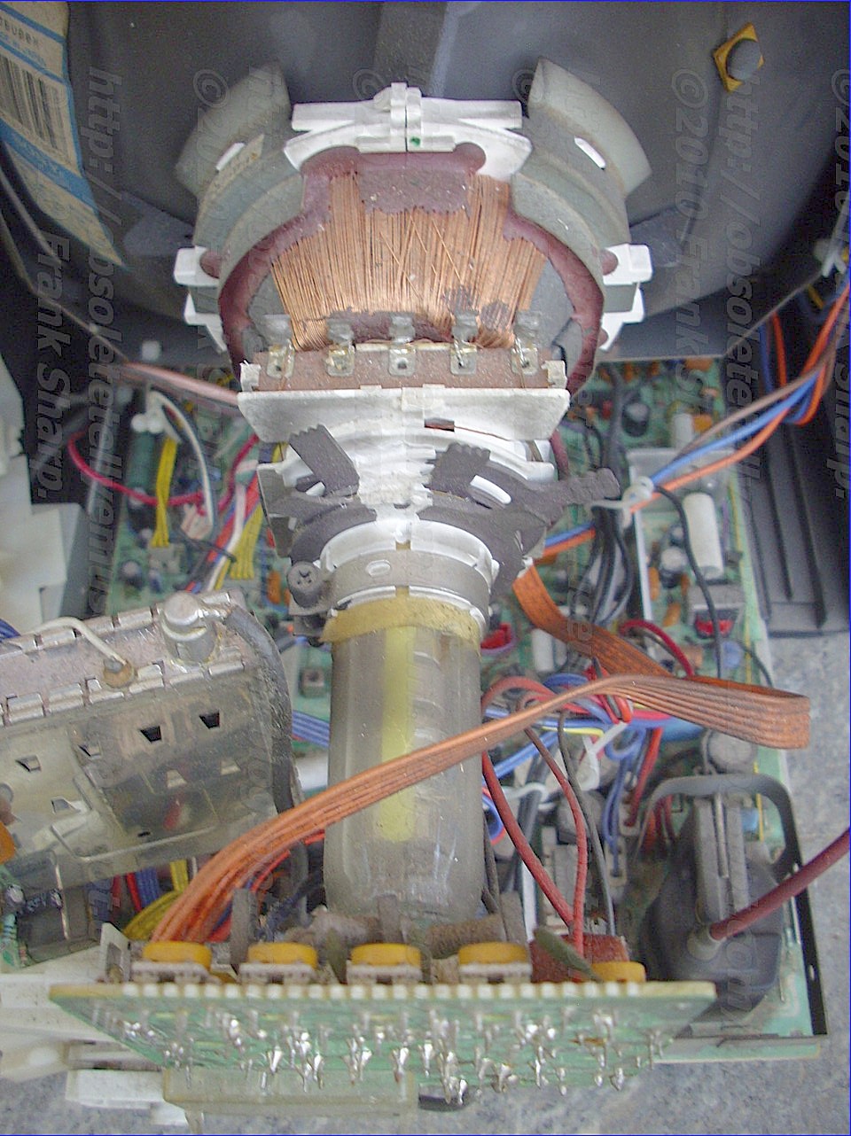
CRT TUBE SONY TRINITRON A34JBU00X VIEW.


----------------------------------------------------------------------------------
Trinitron is Sony's brand name for its line of aperture grille based CRTs used in televisions and computer monitors. One of the first truly new television systems to enter the market since the 1950s, the Trinitron was announced in 1966 to wide acclaim for its bright images, about 25% brighter than common shadow mask televisions of the same era. Constant improvement in the basic technology and attention to overall quality allowed Sony to charge a premium for Trinitron devices into the 1990s.
Patent protection on the basic Trinitron design ran out in 1996, and it quickly faced a number of competitors at much lower price points. Sony responded by introducing their flat-screen FD Trinitron designs (WEGA), which maintained their premier position in the market into the early 2000s. However, these designs were surpassed relatively quickly by plasma and LCD designs. Sony removed the last Trinitron televisions from their product catalogs in 2006, and ceased production in early 2008. Video monitors are the only remaining Trinitron products being produced by Sony, at a low production rate, although the basic technology can still be found in downmarket televisions from 3rd parties.
The name Trinitron was derived from trinity, meaning the union of three, and tron from electron tube, after the way that the Trinitron combined the three separate electron guns of other CRT designs into one.
Trinitron
In the autumn of 1966 Ibuka finally gave in, and announced he would personally lead a search for a replacement for Chromatron. Susumu Yoshida was sent to the U.S. to look for potential licenses, and was impressed with the improvements that RCA had made in overall brightness by introducing new rare earth phosphors on the screen. He also saw General Electric's "Porta-color" design, using three guns in a row instead of a triangle, which allowed a greater portion of the screen to be lit. His report was cause for concern in Japan, where it seemed Sony was falling ever-farther behind the U.S. designs. They might be forced to license the shadow mask system if they wanted to remain competitive.[10]Ibuka was not willing to give up entirely, and had his 30 engineers explore a wide variety of approaches to see if they could come up with their own design. At one point Yoshida asked Senri Miyaoka if the in-line gun arrangement used by GE could be replaced by a single tube with three cathodes; this would be more difficult to build, but be lower cost in the long run. Miyaoka built a prototype and was astonished how well it worked, although it had focussing problems.[10] Later that week, on Saturday, Miyaoka was summoned to Ibuka's office while he was attempting to leave work to attend his weekly cello practice. Yoshida had just informed Ibuka about his success, and the two asked Miyaoka if they could really develop the gun into a workable product. Miyaoka, anxious to leave, answered yes, excused himself, and left. That Monday Ibuka announced that Sony would be developing a new color television design, based on Miyaoka's prototype.[11] By February 1967 the focusing problems had been solved, and because there was a single gun, the focusing was achieved with permanent magnets instead of a coil, and required no after manufacturing manual adjustments.During development, Sony engineer Akio Ohgoshi introduced another modification. GE's system improved on the RCA shadow mask by replacing the small round holes with slightly larger rectangles. Since the guns were in-line, they would shine onto the back of the tube onto three rectangular patches instead of three smaller spots, about doubling the lit area. Ohgoshi proposed removing the mask entirely and replacing it with a series of vertical slots instead, lighting the entire screen. Although this would require the guns to be very carefully aligned with the phosphors on the tube in order to ensure they hit the right colors, with Miyaoka's new tube this appeared possible.[11] In practice this proved easy to build but difficult to place in the tube – the fine wires were mechanically weak and tended to move when the tubes were bumped, resulting in shifting colors on the screen. This problem was solved by running fine tungsten wires across the grille horizontally to keep them in place.
The combination of three-in-one electron gun and the replacement of the shadow mask with the aperture grille resulted in a unique and easily patentable product. Officially introduced by Ikuba in April 1968, the original 12 inch Trinitron had a display quality that easily surpassed any commercial set in terms of brightness, color fidelity, and simplicity of operation. The tube was also flat vertically, a side-effect of the vertical wires in the aperture grille, which gave it a unique and appealing look. It was also all solid state, with the exception of the picture tube itself, which allowed it to be much more compact and cool running than designs like GE's Porta-color.
Ikuba ended the press conference by claiming that 10,000 sets would be available by October, well beyond what engineering had told him was possible. Ikuba cajoled Yoshida to take over the effort of bringing the sets into production, and although Yoshida was furious at being put in charge of a task he felt was impossible, he finally accepted the assignment and successfully met the production goal.[12] The KV-1310 was introduced in limited numbers in Japan in October as promised, and in the U.S. as the KV-1310U the following year.
In spite of Trinitron and Chromatron having no technology in common, the shared single electron gun has led to many erroneous claims that the two are similar, or the same.[13]
Despite the statement above claiming that there were no valves inside Trinitron TV sets, for a brief period in the United Kingdom between 1969 and 1971/72, the KV-1320UB was fitted with 3AT2 valves for the extra high tension. Later on, the KV-1320UB was redesigned internally and externally to become all solid-state. Despite containing vacuum tubes, the first version of the KV-1320UB was promoted as being all solid-state. The later version of this model is identified as having no wooden outer-shell. These early color sets intended for the UK market had a PAL decoder that was different from those invented and licensed by Telefunken of Germany, who invented this color system. The decoder inside the UK-sold Sony color Trinitron sets, from the KV-1300UB to the KV-1330UB had an NTSC decoder adapted for PAL. The decoder used a 64 microsecond delay line to store every other line, but instead of using the delay line to average out the phase of the current line and the "remembered" line (as with "Deluxe PAL"), it simply repeats the same line twice. Any phase errors can then be compensated for by using a Tint control on the front of the set.

The Trinitron design incorporates two unique features: the single-gun three-cathode picture tube, and the vertically aligned aperture grille.
The single-gun consists of a long-necked tube with a single electrode at its base, flaring out into a horizontally-aligned rectangular shape with three vertically-aligned rectangular cathodes inside. Each cathode is fed the amplified signal from one of the decoded RGB signals.
The electrons from the cathodes are all aimed toward a single point at the back of the screen where they hit the aperture grille, a steel sheet with vertical slots cut in it. Due to the slight separation of the cathodes at the back of the tube, the three beams approach the grille at slightly different angles. When they pass through the grille they retain this angle, hitting their individual colored phosphors that are painted in vertical stripes on the inside of the tube. The main purpose of the grille is to ensure the beams are properly registered with the phosphors.
Advantages
In comparison to early shadow mask designs, the Trinitron grille cuts off much less of the signal coming from the electron guns. RCA sets built in the 1950s cut off about 85% of the incoming signal, while the grille cuts off about 25%. Improvements to the shadow mask designs continually narrowed this difference in the two designs, and by the late 1980s the difference in performance, at least theoretically, was eliminated.Another advantage of the aperture grille was that the distance between the wires remained constant vertically across the screen. In the shadow mask design the size of the holes in the mask is defined by the required resolution of the phosphor dots on the screen, which was constant. However, the distance from the guns to the holes changed; for dots near the center of the screen the distance was its shortest, at points in the corners it was at its maximum. To ensure that the guns were focused on the holes, a system known as dynamic convergence had to constantly adjust the focus point as the beam moved across the screen. In the Trinitron design the problem was greatly simplified, requiring changes only for large screen sizes, and only on a line-by-line basis.
For this reason, Trinitron systems are easier to focus than shadow masks, and generally had a sharper image. This was a major selling point of the Trinitron design for much of its history. In the 1990s new computer controlled real-time feedback focusing systems eliminated this advantage, as well as leading to the introduction of "true flat" designs.
Visible Support Wires
Even small changes in the alignment of the grille over the phosphors can cause the coloring to shift. Since the wires are thin, small bumps can cause the wires to shift alignment if they are not held in place. Monitors using this technology have one or more thin tungsten wires running horizontally across the grille to prevent this. Screens 15" and below have one wire located about two thirds of the way down the screen, while monitors greater than 15" have 2 wires at the one-third and two-thirds positions. These wires are less apparent or completely obscured on standard definition sets due to larger scan lines of the video being displayed. On computer monitors, where the lines are much closer together, the wires are often visible. This is a minor drawback of the Trinitron standard which is not shared by shadow mask CRTs.CATHODE-RAY TUBE - CRT TUBE SONY TRINITRON ELECTRON GUN TECHNOLOGY OVERVIEW:
In a cathode ray tube, for example, a color picture tube in which a plurality of electron beams are made to converge or cross each other substan
tially at the optical center of an electrostatic focusing lens by which the beams are focused on the electron-receiving screen of the tube; the focusing lens includes first and second axially spaced, annular electrodes extending around the tube axis and being at the same potential, and a third annular electrode assembly extending between the first and second electrodes and which includes an axial array of at least three annular electrode portions, the electrode portions at the ends of the axial array being at a different potential than the first and second electrodes to establish the focusing electric field and at least one of the electrode portions intermediate the end portions being at a potential that deviates from the potential of the end electrode portions in a direction toward the potential of the first and second electrodes to modify the electric field so that its equivalent optical lens has relatively flatter surfaces for further reducing aberrations of the beam or beams focused thereby.1. In a cathode ray tube having beam producing means generating at least one electron beam and a phosphor screen positioned to have the beam impinge thereon; electron focusing lens means for focusing the beam on the screen comprising: 2. A cathode ray tube according to claim 1, in which: 3. A cathode ray tube according to claim 1, in which: 4. A cathode ray tube according to claim 1, in which: 5. A cathode ray tube according to claim 1, in which: 6. A cathode ray tube according to claim 1, in which: 7. A cathode ray tube according to claim 6, in which:
Description:
This invention generally relates to cathode ray tubes, and is particularly directed to improvements in the electrostatic lens of such tubes by which the electron beam or beams are focused on the electron-receiving screen of the tube.
In cathode ray tubes having an electron gun of the unipotential type, each electron beam is passed through the electric field of the electrostatic focusing lens so as to be focused thereby on the screen, and such lens usually comprises first and second axially spaced, annular electrodes extending around the tube axis and being at the same potential, and a third annular electrode extending between the first and second electrodes and being at a different potential, for example, at a substantially lower potential, to establish the focusing electric field. In order to minimize spherical aberrations of the beam focused on the screen, it is desirable that the electrostatic focusing lens be equivalent to an optical lens of large diameter and having relatively flat surfaces, that is, surfaces with large radii of curvature:
In an electrostatic focusing lens, the surface curvatures of the equivalent optical lens are dependent upon the gradient of the potential along the optical axis between the first and second electrodes, and the gradient of the potential is, in turn, dependent upon the potential difference between the first and second electrodes and the third or intermediate electrode and also upon the axial distance between the first and second electrodes and the diameter of the third electrode. Since the electron gun is positioned within the neck of the cathode ray tube envelope, it will be apparent that the diameter of the third or intermediate electrode of the electrostatic focusing lens is limited by the diameter of the neck. Thus, the diameter of the equivalent optical lens can be increased by increasing the diameter of the intermediate electrode only to a limited extent. If the axial distance between the first and second or end electrodes of the electrostatic focusing lens is reduced to decrease the potential gradient in the field along the optical axis, and hence to increase the radii of curvature of the surfaces of the equivalent optical lens, the focusing effect of the lens is decreased and, therefore, it is necessary to undesirably increase the distance from the focusing lens to the screen and also the overall length of the tube. If the potential difference between the intermediately electrode and the end electrodes is to be reduced, it becomes necessary to apply a relatively high voltage to the intermediate electrode, bearing in mind that the end electrodes are usually at the anode voltage which is generally in the range of from 13 to 20 kv. The application of a relatively high voltage, such as, a voltage of 4 to 5 kv. or more, to the intermediate electrode is disadvantageous in that it requires additional circuitry for producing that high voltage, and further in in that there is the possibility of discharges occurring between the closely spaced leads and pins that supply the voltages to the intermediate electrode and to the grids by which the beam is produced and modulated.
The need for an electrostatic focusing lens of single-gun, equivalent to an optical lens of large diameter and having surfaces of large radii of curvature is particularly acute in the case of single-gun, plural-beam cathode ray tubes of the type disclosed in U.S. Pat. No. 3,448,316, issued June 3, 1969, and having a common assignee herewith.
In such single-gun, plural-beam cathode ray tubes adapted for use as a color picture tube in a television receiver, a cathode structure emits electrons which are formed into a plurality of electron beams and such beams are made to converge or cross each other substantially at the optical center of an electrostatic focusing lens which is common to all the beams and focuses the beams on the electron-receiving screen. The fact that all of the beams pass through the center of the focusing lens diminishes the aberrations introduced by the latter as compared with earlier proposed arrangements in which at least two of the beams pass through the focusing lens at substantial distances from the optical axis. However, optimum reduction of aberration again requires that the electrostatic focusing lens for focusing the beams which converge to cross each other at its optical center be equivalent to an optical lens of large diameter having surfaces of large radii of curvature.
One suitable method of achieving an electrostatic focusing lens equivalent to an optical lens of large diameter and having surfaces of large radii of curvature is disclosed in my copending patent application, Ser. No. 846,533, filed July 21, 1969 corresponding to Japanese Pat. application No. 93589/68, filed Dec. 19, 1968; wherein an auxiliarly electrode is disposed within the intermediate electrode of the lens to reduce the potential gradient in the focusing electric field; however, there are other suitable methods of achieving this result without the necessity of utilizing an auxiliary electrode.
Accordingly, it is an object of this invention to provide a unipotential, focusing type electron gun for a single-beam or plural-beam cathode ray tube in which the electrostatic focusing lens is made equivalent to an optical lens of large diameter having surfaces of large radii of curvature, without unduly increasing the diameter of the tube neck or the length of the tube and further without reducing the focusing effect of the lens.
In a cathode ray tube according to an aspect of this invention, for example, a color picture tube in which a plurality of electron beams are made to converge or cross each other substantially at the optical center of an electrostatic focusing lens by which the beams are all focused on the electron-receiving screen of the tube; the electrostatic focusing lens is constituted by first and second axially spaced, annular electrodes extending around the tube axis and being at the same potential, for example, approximately the anode voltage of the tube, and a third annular electrode assembly extending between the first and second electrodes and which includes an axial array of at least three annular electrode portions, the electrode portions and the ends of the axial array being at a different potential than the first and second electrodes, for example, a voltage substantially lower than the anode voltage, to establish the focusing electric field, while at least one of the electrode portions intermediate the end portions is at a potential that deviates from the potential of the end electrode portions, in a direction toward the potential of the first and second electrodes, for example, the same potential of approximately the anode voltage of the tube, so as to reduce the potential gradient in the focusing electric field and thereby make the electrostatic lens equivalent to a large diameter optical lens having surfaces with large radii of curvature.
In an electrostatic focusing lens for a cathode ray tube, as aforesaid, the axial array preferably comprises an odd number of electrode portions spaced apart from each other, with the one electrode portion being in the middle of the array.
The above, and further object, features and advantages of the invention, will appear from the following detailed description of illustrative embodiments of the invention which is to be read in conjunction with the accompanying drawings, in which:
FIG. 1 is a diagrammatic axial sectional view of a conventional single-beam, unipotential focusing electron gun;
FIG. 2 is a fragmentary axial sectional view of an electrostatic focusing lens in accordance with an embodiment of the present invention;
FIG. 3A is a graphical illustration of the variations of potential along the tube axis in focusing lenses according to the prior art and this invention, respectively;
FIGS. 3B and 3C are graphical illustrations of the lines of equal potential in focusing lenses according to the prior art and this invention, respectively;
FIG. 4 is a fragmentary axial sectional view of a color picture tube employing an electrostatic focusing lens according to the present invention.
 Referring to the drawings in detail, and initially to FIG. 1 thereof, it will be seen that a conventional single-beam unipotential electron gun 10 for a cathode ray tube is there shown to include a cathode 11 constituting an electron beam generating source, first and second control grids 12 and 13 having aligned apertures 14 and 15, respectively, and an electrostatic focusing lens 16. The lens 16 includes first and second end electrodes 17 and 18 which are annular, axially spaced from each other and coaxial with the tube axis x--x, and a relatively larger diameter third or intermediate annular electrode 19 which is also coaxial with the tube axis and extends between end electrodes 17 and 18 and axially overlaps the latter.
In operating the electron gun 10, appropriate voltages are applied to grids 12 and 13 and to electrodes 17, 18 and 19. For example, with the voltage of cathode 11 as a reference, a voltage of 0 to -400 v. is applied to first grid 12 for modulating the beam, a voltage of 0 to 500 v. is applied to grid 13 to cause the bundle of electrons of the single-beam to converge to a point source substantially within aperture 15, a voltage of 13 to 20 kv. is applied to the intermediate electrode 19.
The voltage applied to electrodes 17 and 18 may conveniently be anode voltage applied to the conductive layer 24 at the inner surface of the tube which further has a phosphor screen 23 for receiving the electrons of the single beam 25. With the distribution of applied voltages, as given above, the bundle or rays of electrons of beam 25 which diverge from the tube axis x--x after passing through aperture 15 are converged or focused at a point on screen 23 by passage through the electric field thus established within electrode 19 between electrodes 17 and 18, and which is equivalent to an optical lens represented in broken lines at L on FIG. 1 and centered between electrodes 17 and 18.
When the axial distance between electrodes 17 and 18 is sufficient to ensure that the overall length of the tube is not undersirably large and the diameter of electrode 19 is suitable to permit a reasonable diameter of the tube neck, the field of electrostatic focusing lens 16 has a steep potential gradient as indicated by the curve P on FIG. 3A which represents the potentials along the tube axis x--x at various distances from the plane y--y passing through the optical center of lens 16 or its equivalent optical lens L. With such a steep potential gradient, the equivalent optical lens L is of limited diameter and has surfaces with relatively small radii of curvature. As shown graphically on FIG. 3B, the small radii of curvature of the surfaces of equivalent optical lens L result from the steep gradient of the lines p of equal potential within the electric field of electrostatic focusing lens 16, which lines p as shown, are at substantial angles with respect to axis x--x.
Thus, in focusing beam 25, the conventional electrostatic lens 16 may impart spherical aberrations to the beam with resultant poor resolution of the picture produced when the beam is made to scan screen 23, as by the usual deflection yoke (not shown).
In accordance with this invention, the above-mentioned spherical aberrations are substantially diminished by providing an axial array of at least three electrode portions in place of the conventional single intermediate electrode of the electrostatic lens 16, with the electrode portions at the ends of the array being at a different potential than the end electrodes of equal potential and with at least one intermediate electrode portion being at a potential different from the end portions and approaching the potential of the end electrodes to reduce the angles of the lines p' (FIG. 3C) of equal potential with respect to the tube axis x--x and to decrease the potential gradient along such axis, as indicated at P' on FIG. 3A, whereby to make the electrostatic lens equivalent to an optical lens L' (FIG. 3A) of relatively large diameter and having surfaces of large radii of curvature.
As shown on FIG. 2, in which the several parts of an electrostatic focusing lens 16a are identified by the same reference numerals employed in connection with the above description of FIG. 1, but with the letter "a" appended thereto, the electrostatic focusing lens 16a provided according to this invention is there shown to be comprised of end electrodes 17a and 18a, and an intermediate electrode assembly, generally indicated by the reference numeral 19a, in the form of an axial array of three electrode portions 30, 31, and 32. Although assembly 19a is shown for purposes of illustration to have three electrode portions, a larger, preferably odd number of electrode portions may be provided.
In the illustrated embodiment, the end electrode portions 30, 32 of the axial array constituting electrode 19a are at a potential substantially different from the potential of the end electrodes 17a and 18a, and may be connected to each other by a conductor 33. More specifically, the potential of electrode portions 30 and 32 may be substantially lower than the potential of end electrodes 17a and 18a, and may typically be 0 v. to 600 v. compared to 13 kv. to 20 kv. for end electrodes 17a and 18a. The potential difference provides an electric focusing field between the end electrodes 17a, 18a and the intermediate electrode assembly 19a.
The intermediate electrode portion 31 of the axial array is at a potential which deviates or is different from the potential of end electrode portions 30, 32 in the direction toward the potential of end electrodes 17a and 18a, and may typically be at the same relatively high potential, such as the anode voltage applied to the conductive layer at the inner surface of the tube, as is applied to end electrodes 17a and 18a. The means for applying this deviating potential to intermediate electrode portion 31 may be a separate source of potential (not shown) or, when it is desired to apply the same potential to intermediate electrode portion 31 as is applied to end electrodes 17a and 18a, electrode portion 31 may be connected to the end electrodes 17a and 18a by a conductor 35 connected to the end electrode interconnection 20a.
The overall effect of the intermediate electrode assembly 19a, with the potential differences associated with its various electrode portions 30, 31, 32, is to very substantially reduce the potential gradient along the tube axis between electrodes 17a and 18a and to decrease the angles with respect to the tube axis of the lines of equal potential within the field, with the result that the equivalent optical lens L' (FIG. 3A) is of large diameter and has surfaces of large radii of curvature, as is desired.
The electrode portion s 30, 31, 32 comprising intermediate electrode assembly 19a are shown spaced apart from each other in the axial array and, when assembly 19a has an odd number of at least three electrode portions, as is preferred, at least the intermediate electrode portion situated at the middle of the axial array is at a higher potential than the end electrode portions.
Of course, the surface radii of the equivalent optical lens can also be changed by changing the distance between electrodes 17a and 18a, the potential difference between electrodes 17a and 18a and end electrode portions 30 and 32, and the potential difference between end electrode portions 30 and 32, and the intermediate electrode portion 31. Thus, the invention permits an electrostatic focusing lens to be obtained that is equivalent to an optical lens with precisely desired surface radii.
Although the invention has been described above with reference to its application to single-beam cathode ray tubes, reference to FIG. 4 will show the application of the invention to a single-gun, plural-beam cathode ray tube of the type disclosed in detail in U.S. Pat. No. 3,448,316. In the cathode ray tube of FIG. 4, three electrically separated cathodes K R , K G , and K B have "red", "green" and "blue" video signals respectively supplied thereto. The three cathodes are arranged with their electron emitting surfaces in a straight line so as to be aligned with similarly arranged apertures in a first grid G 1 . A second cup-shaped grid G 2 has an end plate disposed adjacent grid G 1 and formed with apertures aligned with the apertures of first grid G 1 . Arranged in order following the grid G 2 in the direction away from control grid G 1 are an open-ended tubular electrode 117, an electrode assembly 119 consisting of an axially array electrode portions 130, 131, 132, and an open-ended tubular electrode 118 constituting an electrostatic focusing lens 116. Electrode 117 includes a relatively small diameter end portion 117a, and is supported with such end portion extending into cup-shaped grid G 2 and spaced radially from the side wall of the latter.
When voltages similar to those indicated for the cathode ray tube of FIG. 1 are applied to grids G 1 and G 2 and electrodes 117, 118, and to the portions of electrode assembly 119 in a manner in accordance with the invention, beams B R , B G , and B B emitted by cathodes K R , K G , and K B are modulated with the three different video signals applied between grid G 1 and the respective cathodes. Grid G 2 and the end portion 117a of electrode 117 cooperate to provide an electric field defining an electrostatic beam converging lens illustrated in broken lines by its optical equivalent 1 and which is operative to converge beams B R and B B toward beam B G so that the three beams cross each other substantially at the location of the optical center of the focusing lens 116.
In order to cause convergence of the beams B R and B B which emerge from electrode 118 along divergent paths, the electron gun of FIG. 4 further has deflecting means 36 that includes shielding plates 37 and 37' provided in spaced opposing relationship to each other and extending axially away from the free end of electrode 118. Deflecting means 36 further includes converging deflector plates 38 and 38', which may be flat, as shown, or outwardly convexly bent or curved, and which are mounted in spaced opposing relation to the outer surfaces of shielding plates 37 and 37' respectively. The plates 37 and 37' and the plates 38 and 38' are disposed so that the beams B B , B G , and B R pass between the plates 37 and 38, between the plates 37 and 37' and between the plates 37' and 38', respectively. The outer plates 38 and 38' may be mounted by attachment to electrode 118, as shown, while plates 37 and 37' are supported from plates 38 and 38' and insulated therefrom, as by insulating supports 39.
A high anode voltage V p , for example of 13 to 20 kv., provided by a source 40 is applied by way of an anode button 41 to the usual conductive layer 42 lining the tube envelope, and a spring contact 43 extends from plate 37 into engagement with layer 42. The high voltage V p thus applied to plate 37 is transmitted to plate 37' by a conductor 44 therebetween. A voltage (V p -V c ) which is lower than the voltage V p by 200 to 300 v., constituting a convergence voltage, is applied to outer plates 38 and 38'. The source of the convergence voltage V c is indicated at 45 and may provide a static convergence voltage and also, if desired, a dynamic convergence voltage varied in accordance with the scanning action. As shown, the voltage (V p -V c ) may be applied by way of a button 46 in the tube neck 47 and a conductor 48 to electrode 117 of focusing lens 116. Further, electrode 118 and intermediate electrode portion 131 are connected with electrode 117 by conductors 49, 50 to receive the voltage (V p -V c ) and, since outer plates 38 and 38' are mounted directly on electrode 118, plates 38 and 38' also receive the voltage (V p -V c ). Thus, convergence voltage differences V c are applied between plates 37 and 38 and between plates 37' and 38' so that beam B B and B R will cross each other and beam B G at a common spot on an aperture grill or mesh 51 and diverge therefrom to strike respective color phosphors b, r and g arranged in suitable arrays to constitute the color screen 52 on the face plate 53 of the tube. A deflection yoke 54 is also provided to cause beams B R , B G , and B B to simultaneously scan screen 52 in the usual manner. The end electrode portions 130, 132 may be electrically connected with a source at low potential, as previously described with respect to similar electrode portions 30, 32 of FIG. 2, by a conductor 55 and may be electrically connected together by another conductor 56 so as to have the same potential applied to both portions 30, 32. The conductor 55 may be electrically connected to one of the pins of the tube, which in turn may be connected to the source of low potential (not shown). Since beams B R , B G and B B all pass substantially through the optical center of electrostatic focusing lens 116 so as to be focused thereby on screen 52, lens 116 imparts diminished aberration to the resulting beam spots on the screen as compared with earlier arrangements in which, for example, beams B R and B B pass through the focusing lens at substantial distances from its optical axis. However, since beams B R and B B pass through lens 116 at substantial angles to the optical or tube axis, optimum reduction or avoidance of aberrations of the beam spots requires that lens 116 be equivalent to a large diameter optical lens having surfaces with large radii of curvature. Thus, in accordance with this invention, the optical lens L' equivalent to electrostatic focusing lens 116 is made to have a large diameter and surfaces with large radii of curvature by providing lens 116 with the intermediate electrode assembly 119 comprised of an axial array of at least three annular electrode portions 130, 131, 132, having the potential differences associated therewith, as previously described. Since the middle electrode portion 131 of the array is at a different potential than end electrode portions 130, 132, the effect is to reduce the potential gradient of the electric field of lens 116, and thus to provide the latter with the desired optical equivalent of a lens of large diameter and large radii of curvature.
Although illustrative embodiments of electrostatic lenses according to this invention have been described in detail herein with reference to the accompanying drawings, it is to be understood that the invention is not limited to those precise embodiments and that various changes and modifications may be made therein by one skilled in the art without departing from the scope or spirit of the invention.
ELECTRON GUN DEVICE FOR COLOR TUBE SONY TRINTRON CRT TUBE TECHNOLOGY:
An electron gun device for color television picture tubes. The electron gun has three cathodes and a plurality of grids. Means are provided for equalizing the cutoff voltages of the cathodes by equalizing the intensity of the electric field reaching the cathodes from the grids. Equalization preferably is obtained by making one or more of the apertures in the first and second grids of a diameter different from that of the other apertures, or by making the distances of one or more of the cathodes from the grids different from the corresponding distances of the other cathodes, or by a combination of both of these arrangements.
1. An electron gun device for a color picture tube comprising two side cathodes and a central cathode therebetween having beam generating surfaces arranged substantially in a row for emitting electrons generally in parallel directions, first and second grids spaced successively in the axial direction away from said beam generating surfaces and having apertures respectively aligned with the beam generating surfaces and through which the emitted electrons are collimated into respective electron beams, and a plurality of electrodes maintained at different potentials and arranged axially following said second grid to provide an electric field defining a main lens means by which said beams are focused and cooperating with said second grid to provide another electric field defining an auxiliary lens means by which the beams from said side cathodes are converged with respect to the beam from said central cathode for passage of all of the beams through the center of said main lens means, the angle of a cone that can be projected to the center of said beam generating surface of said central cathode from the peripheries of the respective aligned apertures of said grids being smaller than the angles of the corresponding cones for said side cathodes for equlizing the effects of said other electric field at said beam generating surfaces of said cathodes so that the latter will have equal cutoff voltages. 2. An electron gun according to claim 1, in which at least one of the apertures of said first and second grids which are aligned with said central cathode is of a size smaller than the sizes of the apertures of said grid aligned with said side cathodes. 3. An electron gun according to claim 1, in which said beam generating surface of the central cathode is at a distance from the aligned aperture in at least one of said first and second grids that is greater than the distance from the beam generating surfaces of said side cathodes to the corresponding apertures of the grids.
In cathode ray tubes having an electron gun of the unipotential type, each electron beam is passed through the electric field of the electrostatic focusing lens so as to be focused thereby on the screen, and such lens usually comprises first and second axially spaced, annular electrodes extending around the tube axis and being at the same potential, and a third annular electrode extending between the first and second electrodes and being at a different potential, for example, at a substantially lower potential, to establish the focusing electric field. In order to minimize spherical aberrations of the beam focused on the screen, it is desirable that the electrostatic focusing lens be equivalent to an optical lens of large diameter and having relatively flat surfaces, that is, surfaces with large radii of curvature:
In an electrostatic focusing lens, the surface curvatures of the equivalent optical lens are dependent upon the gradient of the potential along the optical axis between the first and second electrodes, and the gradient of the potential is, in turn, dependent upon the potential difference between the first and second electrodes and the third or intermediate electrode and also upon the axial distance between the first and second electrodes and the diameter of the third electrode. Since the electron gun is positioned within the neck of the cathode ray tube envelope, it will be apparent that the diameter of the third or intermediate electrode of the electrostatic focusing lens is limited by the diameter of the neck. Thus, the diameter of the equivalent optical lens can be increased by increasing the diameter of the intermediate electrode only to a limited extent. If the axial distance between the first and second or end electrodes of the electrostatic focusing lens is reduced to decrease the potential gradient in the field along the optical axis, and hence to increase the radii of curvature of the surfaces of the equivalent optical lens, the focusing effect of the lens is decreased and, therefore, it is necessary to undesirably increase the distance from the focusing lens to the screen and also the overall length of the tube. If the potential difference between the intermediately electrode and the end electrodes is to be reduced, it becomes necessary to apply a relatively high voltage to the intermediate electrode, bearing in mind that the end electrodes are usually at the anode voltage which is generally in the range of from 13 to 20 kv. The application of a relatively high voltage, such as, a voltage of 4 to 5 kv. or more, to the intermediate electrode is disadvantageous in that it requires additional circuitry for producing that high voltage, and further in in that there is the possibility of discharges occurring between the closely spaced leads and pins that supply the voltages to the intermediate electrode and to the grids by which the beam is produced and modulated.
The need for an electrostatic focusing lens of single-gun, equivalent to an optical lens of large diameter and having surfaces of large radii of curvature is particularly acute in the case of single-gun, plural-beam cathode ray tubes of the type disclosed in U.S. Pat. No. 3,448,316, issued June 3, 1969, and having a common assignee herewith.
In such single-gun, plural-beam cathode ray tubes adapted for use as a color picture tube in a television receiver, a cathode structure emits electrons which are formed into a plurality of electron beams and such beams are made to converge or cross each other substantially at the optical center of an electrostatic focusing lens which is common to all the beams and focuses the beams on the electron-receiving screen. The fact that all of the beams pass through the center of the focusing lens diminishes the aberrations introduced by the latter as compared with earlier proposed arrangements in which at least two of the beams pass through the focusing lens at substantial distances from the optical axis. However, optimum reduction of aberration again requires that the electrostatic focusing lens for focusing the beams which converge to cross each other at its optical center be equivalent to an optical lens of large diameter having surfaces of large radii of curvature.
One suitable method of achieving an electrostatic focusing lens equivalent to an optical lens of large diameter and having surfaces of large radii of curvature is disclosed in my copending patent application, Ser. No. 846,533, filed July 21, 1969 corresponding to Japanese Pat. application No. 93589/68, filed Dec. 19, 1968; wherein an auxiliarly electrode is disposed within the intermediate electrode of the lens to reduce the potential gradient in the focusing electric field; however, there are other suitable methods of achieving this result without the necessity of utilizing an auxiliary electrode.
Accordingly, it is an object of this invention to provide a unipotential, focusing type electron gun for a single-beam or plural-beam cathode ray tube in which the electrostatic focusing lens is made equivalent to an optical lens of large diameter having surfaces of large radii of curvature, without unduly increasing the diameter of the tube neck or the length of the tube and further without reducing the focusing effect of the lens.
In a cathode ray tube according to an aspect of this invention, for example, a color picture tube in which a plurality of electron beams are made to converge or cross each other substantially at the optical center of an electrostatic focusing lens by which the beams are all focused on the electron-receiving screen of the tube; the electrostatic focusing lens is constituted by first and second axially spaced, annular electrodes extending around the tube axis and being at the same potential, for example, approximately the anode voltage of the tube, and a third annular electrode assembly extending between the first and second electrodes and which includes an axial array of at least three annular electrode portions, the electrode portions and the ends of the axial array being at a different potential than the first and second electrodes, for example, a voltage substantially lower than the anode voltage, to establish the focusing electric field, while at least one of the electrode portions intermediate the end portions is at a potential that deviates from the potential of the end electrode portions, in a direction toward the potential of the first and second electrodes, for example, the same potential of approximately the anode voltage of the tube, so as to reduce the potential gradient in the focusing electric field and thereby make the electrostatic lens equivalent to a large diameter optical lens having surfaces with large radii of curvature.
In an electrostatic focusing lens for a cathode ray tube, as aforesaid, the axial array preferably comprises an odd number of electrode portions spaced apart from each other, with the one electrode portion being in the middle of the array.
The above, and further object, features and advantages of the invention, will appear from the following detailed description of illustrative embodiments of the invention which is to be read in conjunction with the accompanying drawings, in which:
FIG. 1 is a diagrammatic axial sectional view of a conventional single-beam, unipotential focusing electron gun;
FIG. 2 is a fragmentary axial sectional view of an electrostatic focusing lens in accordance with an embodiment of the present invention;
FIG. 3A is a graphical illustration of the variations of potential along the tube axis in focusing lenses according to the prior art and this invention, respectively;
FIGS. 3B and 3C are graphical illustrations of the lines of equal potential in focusing lenses according to the prior art and this invention, respectively;
FIG. 4 is a fragmentary axial sectional view of a color picture tube employing an electrostatic focusing lens according to the present invention.
 Referring to the drawings in detail, and initially to FIG. 1 thereof, it will be seen that a conventional single-beam unipotential electron gun 10 for a cathode ray tube is there shown to include a cathode 11 constituting an electron beam generating source, first and second control grids 12 and 13 having aligned apertures 14 and 15, respectively, and an electrostatic focusing lens 16. The lens 16 includes first and second end electrodes 17 and 18 which are annular, axially spaced from each other and coaxial with the tube axis x--x, and a relatively larger diameter third or intermediate annular electrode 19 which is also coaxial with the tube axis and extends between end electrodes 17 and 18 and axially overlaps the latter.
In operating the electron gun 10, appropriate voltages are applied to grids 12 and 13 and to electrodes 17, 18 and 19. For example, with the voltage of cathode 11 as a reference, a voltage of 0 to -400 v. is applied to first grid 12 for modulating the beam, a voltage of 0 to 500 v. is applied to grid 13 to cause the bundle of electrons of the single-beam to converge to a point source substantially within aperture 15, a voltage of 13 to 20 kv. is applied to the intermediate electrode 19.
The voltage applied to electrodes 17 and 18 may conveniently be anode voltage applied to the conductive layer 24 at the inner surface of the tube which further has a phosphor screen 23 for receiving the electrons of the single beam 25. With the distribution of applied voltages, as given above, the bundle or rays of electrons of beam 25 which diverge from the tube axis x--x after passing through aperture 15 are converged or focused at a point on screen 23 by passage through the electric field thus established within electrode 19 between electrodes 17 and 18, and which is
 equivalent to an optical lens represented in broken lines at L on FIG. 1 and centered between electrodes 17 and 18.
When the axial distance between electrodes 17 and 18 is sufficient to ensure that the overall length of the tube is not undersirably large and the diameter of electrode 19 is suitable to permit a reasonable diameter of the tube neck, the field of electrostatic focusing lens 16 has a steep potential gradient as indicated by the curve P on FIG. 3A which represents the potentials along the tube axis x--x at various distances from the plane y--y passing through the optical center of lens 16 or its equivalent optical lens L. With such a steep potential gradient, the equivalent optical lens L is of limited diameter and has surfaces with relatively small radii of curvature. As shown graphically on FIG. 3B, the small radii of curvature of the surfaces of equivalent optical lens L result from the steep gradient of the lines p of equal potential within the electric field of electrostatic focusing lens 16, which lines p as shown, are at substantial angles with respect to axis x--x.
Thus, in focusing beam 25, the conventional electrostatic lens 16 may impart spherical aberrations to the beam with resultant poor resolution of the picture produced when the beam is made to scan screen 23, as by the usual deflection yoke (not shown).
In accordance with this invention, the above-mentioned spherical aberrations are substantially diminished by providing an axial array of at least three electrode portions in place of the conventional single intermediate electrode of the electrostatic lens 16, with the electrode portions at the ends of the array being at a different potential than the end electrodes of equal potential and with at least one intermediate electrode portion being at a potential different from the end portions and approaching the potential of the end electrodes to reduce the angles of the lines p' (FIG. 3C) of equal potential with respect to the tube axis x--x and to decrease the potential gradient along such axis, as indicated at P' on FIG. 3A, whereby to make the electrostatic lens equivalent to an optical lens L' (FIG. 3A) of relatively large diameter and having surfaces of large radii of curvature.
As shown on FIG. 2, in which the several parts of an electrostatic focusing lens 16a are identified by the same reference numerals employed in connection with the above description of FIG. 1, but with the letter "a" appended thereto, the electrostatic focusing lens 16a provided according to this invention is there shown to be comprised of end electrodes 17a and 18a, and an intermediate electrode assembly, generally indicated by the reference numeral 19a, in the form of an axial array of three electrode portions 30, 31, and 32. Although assembly 19a is shown for purposes of illustration to have three electrode portions, a larger, preferably odd number of electrode portions may be provided.In the illustrated embodiment, the end electrode portions 30, 32 of the axial array constituting electrode 19a are at a potential substantially different from the potential of the end electrodes 17a and 18a, and may be connected to each other by a conductor 33. More specifically, the potential of electrode portions 30 and 32 may be substantially lower than the potential of end electrodes 17a and 18a, and may typically be 0 v. to 600 v. compared to 13 kv. to 20 kv. for end electrodes 17a and 18a. The potential difference provides an electric focusing field between the end electrodes 17a, 18a and the intermediate electrode assembly 19a.
The intermediate electrode portion 31 of the axial array is at a potential which deviates or is different from the potential of end electrode portions 30, 32 in the direction toward the potential of end electrodes 17a and 18a, and may typically be at the same relatively high potential, such as the anode voltage applied to the conductive layer at the inner surface of the tube, as is applied to end electrodes 17a and 18a. The means for applying this deviating potential to intermediate electrode portion 31 may be a separate source of potential (not shown) or, when it is desired to apply the same potential to intermediate electrode portion 31 as is applied to end electrodes 17a and 18a, electrode portion 31 may be connected to the end electrodes 17a and 18a by a conductor 35 connected to the end electrode interconnection 20a.
The overall effect of the intermediate electrode assembly 19a, with the potential differences associated with its various electrode portions 30, 31, 32, is to very substantially reduce the potential gradient along the tube axis between electrodes 17a and 18a and to decrease the angles with respect to the tube axis of the lines of equal potential within the field, with the result that the equivalent optical lens L' (FIG. 3A) is of large diameter and has surfaces of large radii of curvature, as is desired.
The electrode portion
s 30, 31, 32 comprising intermediate electrode assembly 19a are shown spaced apart from each other in the axial array and, when assembly 19a has an odd number of at least three electrode portions, as is preferred, at least the intermediate electrode portion situated at the middle of the axial array is at a higher potential than the end electrode portions.Of course, the surface radii of the equivalent optical lens can also be changed by changing the distance between electrodes 17a and 18a, the potential difference between electrodes 17a and 18a and end electrode portions 30 and 32, and the potential difference between end electrode portions 30 and 32, and the intermediate electrode portion 31. Thus, the invention permits an electrostatic focusing lens to be obtained that is equivalent to an optical lens with precisely desired surface radii.
Although the invention has been described above with reference to its application to single-beam cathode ray tubes, reference to FIG. 4 will show the application of the invention to a single-gun, plural-beam cathode ray tube of the type disclosed in detail in U.S. Pat. No. 3,448,316. In the cathode ray tube of FIG. 4, three electrically separated cathodes K R , K G , and K B have "red", "green"
and "blue" video signals respectively supplied thereto. The three cathodes are arranged with their electron emitting surfaces in a straight line so as to be aligned with similarly arranged apertures in a first grid G 1 . A second cup-shaped grid G 2 has an end plate disposed adjacent grid G 1 and formed with apertures aligned with the apertures of first grid G 1 . Arranged in order following the grid G 2 in the direction away from control grid G 1 are an open-ended tubular electrode 117, an electrode assembly 119 consisting of an axially array electrode portions 130, 131, 132, and an open-ended tubular electrode 118 constituting an electrostatic focusing lens 116. Electrode 117 includes a relatively small diameter end portion 117a, and is supported with such end portion extending into cup-shaped grid G 2 and spaced radially from the side wall of the latter.When voltages similar to those indicated for the cathode ray tube of FIG. 1 are applied to grids G 1 and G 2 and electrodes 117, 118, and to the portions of electrode assembly 119 in a manner in accordance with the invention, beams B R , B G , and B B emitted by cathodes K R , K G , and K B are modulated with the three different video signals applied between grid G 1 and the respective cathodes. Grid G 2 and the end portion 117a of electrode 117 cooperate to provide an electric field defining an electrostatic beam converging lens illustrated in broken lines by its optical equivalent 1 and which is operative to converge beams B R and B B toward beam B G so that the three beams cross each other substantially at the location of the optical center of the focusing lens 116.
In order to cause convergence of the beams B R and B B which emerge from electrode 118 along divergent paths, the electron gun of FIG. 4 further has deflecting means 36 that includes shielding plates 37 and 37' provided in spaced opposing relationship to each other and extending axially away from the free end of electrode 118. Deflecting means 36 further includes converging deflector plates 38 and 38', which may be flat, as shown, or outwardly convexly bent or curved, and which are mounted in spaced opposing relation to the outer surfaces of shielding plates 37 and 37' respectively. The plates 37 and 37' and the plates 38 and 38' are disposed so that the beams B B , B G , and B R pass between the plates 37 and 38, between the plates 37 and 37' and between the plates 37' and 38', respectively. The outer plates 38 and 38' may be mounted by attachment to electrode 118, as shown, while plates 37 and 37' are supported from plates 38 and 38' and insulated therefrom, as by insulating supports 39.
A high anode voltage V p , for example of 13 to 20 kv., provided by a source 40 is applied by way of an anode button 41 to the usual conductive layer 42 lining the tube envelope, and a spring contact 43 extends from plate 37 into engagement with layer 42. The high voltage V p thus applied to plate 37 is transmitted to plate 37' by a conductor 44 therebetween. A voltage (V p -V c ) which is lower than the voltage V p by 200 to 300 v., constituting a convergence voltage, is applied to outer plates 38 and 38'. The source of the convergence voltage V c is indicated at 45 and may provide a static convergence voltage and also, if desired, a dynamic convergence voltage varied in accordance with the scanning action. As shown, the voltage (V p -V c ) may be applied by way of a button 46 in the tube neck 47 and a conductor 48 to electrode 117 of focusing lens 116. Further, electrode 118 and intermediate electrode portion 131 are connected with electrode 117 by conductors 49, 50 to receive the voltage (V p -V c ) and, since outer plates 38 and 38' are mounted directly on electrode 118, plates 38 and 38' also receive the voltage (V p -V c ). Thus, convergence voltage differences V c are applied between plates 37 and 38 and between plates 37' and 38' so that beam B B and B R will cross each other and beam B G at a common spot on an aperture grill or mesh 51 and diverge therefrom to strike respective color phosphors b, r and g arranged in suitable arrays to constitute the color screen 52 on the face plate 53 of the tube. A deflection yoke 54 is also provided to cause beams B R , B G , and B B to simultaneously scan screen 52 in the usual manner. The end electrode portions 130, 132 may be electrically connected with a source at low potential, as previously described with respect to similar electrode portions 30, 32 of FIG. 2, by a conductor 55 and may be electrically connected together by another conductor 56 so as to have the same potential applied to both portions 30, 32. The conductor 55 may be electrically connected to one of the pins of the tube, which in turn may be connected to the source of low potential (not shown). Since beams B R , B G and B B all pass substantially through the optical center of electrostatic focusing lens 116 so as to be focused thereby on screen 52, lens 116 imparts diminished aberration to the resulting beam spots on the screen as compared with earlier arrangements in which, for example, beams B R and B B pass through the focusing lens at substantial distances from its optical axis. However, since beams B R and B B pass through lens 116 at substantial angles to the optical or tube axis, optimum reduction or avoidance of aberrations of the beam spots requires that lens 116 be equivalent to a large diameter optical lens having surfaces with large radii of curvature. Thus, in accordance with this invention, the optical lens L' equivalent to electrostatic focusing lens 116 is made to have a large diameter and surfaces with large radii of curvature by providing lens 116 with the intermediate electrode assembly 119 comprised of an axial array of at least three annular electrode portions 130, 131, 132, having the potential differences associated therewith, as previously described. Since the middle electrode portion 131 of the array is at a different potential than end electrode portions 130, 132, the effect is to reduce the potential gradient of the electric field of lens 116, and thus to provide the latter with the desired optical equivalent of a lens of large diameter and large radii of curvature.
Although illustrative embodiments of electrostatic lenses according to this invention have been described in detail herein with reference to the accompanying drawings, it is to be understood that the invention is not limited to those precise embodiments and that various changes and modifications may be made therein by one skilled in the art without departing from the scope or spirit of the invention.
ELECTRON GUN DEVICE FOR COLOR TUBE SONY TRINTRON CRT TUBE TECHNOLOGY:
An electron gun device for color television picture tubes. The electron gun has three cathodes and a plurality of grids. Means are provided for equalizing the cutoff voltages of the cathodes by equalizing the intensity of the electric field reaching the cathodes from the grids. Equalization preferably is obtained by making one or more of the apertures in the first and second grids of a diameter different from that of the other apertures, or by making the distances of one or more
of the cathodes from the grids different from the corresponding distances of the other cathodes, or by a combination of both of these arrangements.1. An electron gun device for a color picture tube comprising two side cathodes and a central cathode therebetween having beam generating surfaces arranged substantially in a row for emitting electrons generally in parallel directions, first and second grids spaced successively in the axial direction away from said beam generating surfaces and having apertures respectively aligned with the beam generating surfaces and through which the emitted electrons are collimated into respective electron beams, and a plurality of electrodes maintained at different potentials and arranged axially following said second grid to provide an electric field defining a main lens means by which said beams are focused and cooperating with said second grid to provide another electric field defining an auxiliary lens means by which the beams from said side cathodes are converged with respect to the beam from said central cathode for passage of all of the beams through the center of said main lens means, the angle of a cone that can be projected to the center of said beam generating surface of said central cathode from the peripheries of the respective aligned apertures of said grids being smaller than the angles of the corresponding cones for said side cathodes for equlizing the effects of said other electric field at said beam generating surfaces of said cathodes so that the latter will have equal cutoff voltages. 2. An electron gun according to claim 1, in which at least one of the apertures of said first and second grids which are aligned with said central cathode is of a size smaller than the sizes of the apertures of said grid aligned with said side cathodes. 3. An electron gun according to claim 1, in which said beam generating surface of the central cathode is at a distance from the aligned aperture in at least one of said first and second grids that is greater than the distance from the beam generating surfaces of said side cathodes to the corresponding apertures of the grids.
Description:
This invention relates to an electron gun device, and particularly to an electron gun device for a single-gun, plural-beam type of color television picture tube.
In certain prior color picture tubes having multiple cathodes, the cutoff voltages of the cathodes are not equal to one another. The result of this imbalance is that the gamma characteristics of the three colors in the picture produced by the tube are different and the colors are not natural.
In view of the foregoing, a major object of this invention is to provide a plural-cathode electron gun device whose cathodes have the same cutoff voltages. A further object of the invention is to provide a relatively simple and inexpensive means for equalizing the cutoff voltages of such cathodes.
In accordance with the present invention, the foregoing objects are met by the provision of means for equalizing the cathode cutoff voltages by equalizing the intensity of the electric field reaching the cathodes from the grids of the electron gun. The equalization means selectively limits the amount of flux reaching one or more of the cathodes. In the preferred embodiment of the invention, equalization is accomplished by making one or more of the apertures in the first and second grids of a diameter different from that of the other apertures, or by making the distances of one or more of the cathodes from the grids different from the corresponding distances of the other cathodes, or by a combination of both of these arrangements.
Further objects and advantages of the invention will be pointed out or made apparent in the following description and drawings.
In the drawings:
FIG. 1 shows a typical color television picture tube in which the electron gun of this invention can be used;
FIG. 2 is an enlarged, broken-away partially schematic view of a portion of the electron gun shown in FIG. 1;
FIGS. 3A, 3B, 4A, 4B and 4C are views similar to that of FIG. 2, each showing a different embodiment of the invention;
FIG. 5 is an enlarged detailed view of the preferred embodiment of the invention; and
FIG. 6 is a graph illustrating certain performance characteristics of the electron gun of the present invention.
FIG. 1 of the drawings shows a single-gun, plural-beam color picture tube 10 which is described in detail in U. S. Pat. application Ser. No. 697,414, filed on Jan. 12, 1968, and assigned to the same assignee as this application. The color picture tube 10, which is known by the name "Trinitron," includes a glass envelope 11 (indicated in broken lines) having a neck 12 and cone 13 extending from the neck to a color screen S provided with the usual arrays of color phosphors S R , S G , and S B and with an apertured beam-selecting grid or shadow mask G P . Disposed within the neck 12 is an electron gun A having cathodes K R , K G , and K B , each of which is a beam-generating source with its thermal electron-emitting surface disposed as shown in a plane which is substantially perpendicular to the longitudinal axis of the electron gun A. In the embodiment shown, the beam-generating surfaces are arranged in a straight line so that the respective beams B R , B G and B B emitted therefrom are directed in substantially horizontal planes, with the alignment of the central beam B G being coincident with the axis of the gun.
A first grid G 1 is spaced from the beam-generating surfaces of cathodes K R , K G and K B and has apertures g 1R , g 1G , and g 1B formed therein in alignment with the respective cathode beam-generating surfaces. A common grid G 2 is spaced from the first grid G 1 and has apertures g 2R , g 2G and g 2B formed therein in alignment with the respective apertures of the first grid G 1 . Successively arranged in the axial direction away from the common grid G 2 are open-ended, tubular grids or electrodes G 3 , G 4 and G 5 , respectively, with cathodes K R , K G and K B , grids G 1 and G 2 , and electrodes G 3 , G 4 and G 5 being maintained in the assembled positions shown in the drawings by means of suitable non-illustrated support means of an insulating material.
For operation of the electron gun A of FIG. 1, appropriate voltages are applied to the grids G 1 and G 2 and to the electrodes G 3 , G 4 and G 5 . Thus, for example, a voltage of 0 to minus 400V is applied to the grid G 1 , a voltage of 0 to 500V is applied to the grid G 2 , a voltage of 13 to 20KV is applied to the electrodes G 3 and G 5 , and a voltage of 0 to 400V is applied to the electrode G 4 , with all of these voltages being based upon the cathode voltage as a reference. As a result, the voltage distributions between the respective electrodes and cathodes, and the respective lengths and diameters thereof, may be substantially identical with those of a unipotential-single beam type of electron gun which has a single cathode and first and second single-apertured grids.
With the applied voltage distribution as described hereinabove, an electron lens field will be established between grid G 2 and the electrode G 3 to form an auxiliary lens L' as indicated in dashed lines, and an electron lens field will be established around the axis of electrode G 4 , by the electrodes G 3 , G 4 and G 5 , to form a main lens L, again as indicated in dashed lines. In a typical use of electron gun A, bias voltages of 100 V are applied to the cathodes K R , K G and K B , and bias voltages of 0V, 300V, 20KV, 200V and 20KV may be applied, respectively, to the first and second grids G 1 and G 2 , and the electrodes G 3 , G 4 and G 5 .
Further included in the electron gun A of FIG. 1 are electron beam convergence deflecting means F which comprise shielding plates P and P' disposed in the depicted spaced relationship at opposite sides of the gun axis, and axially extending deflector plates Q and Q' which are disposed, as shown, in outwardly-spaced, opposed relationship to shielding plates P and P', respectively. Although depicted as substantially straight, it is to be understood that the deflector plates Q and Q' may, alternatively, be somewhat curved or outwardly bowed, as is well known in the art.
The shielding plates P and P' are equally charged and disposed so that the central electron beam B G will pass substantially undeflected between the shielding plates P and P', while the deflector plates Q and Q' have negative charges with respect to the plates P and P' so that respective electron beams B B and B R will be convergently deflected as shown by the respective passages thereof between the plates P' and Q'. More specifically, a voltage V P which is equal to the voltage applied to the electrode G 5 , may be applied to both shielding plates P and P', and a voltage V Q , which is some 200 to 300V lower than the voltage V P , is applied to the respective deflector plates Q and Q' to result in the respective shielding plates P and P' being at the same potential, and to result in the application of a deflecting voltage difference or convergence deflecting voltages V C between the respective plates P' and Q' and P and Q and it is, of course, this convergence deflecting voltage V C which will impart the requisite convergent deflection to the respective electron beams B B and B R .
In operation, the respective electron beams B R , B G and B B which emanate from the beam generating surfaces of the cathodes K R , K G and K B will pass through the respective grid apertures g 1R , g 1G and g 1B , to be intensity modulated with what may be termed the "red," "green" and "blue" intensity modulation signals applied between the said cathodes and the first grid G 1 . The respective electron beams will then pass through the common auxiliary lens L' to cross each other at the center of the main lens L. Thereafter, the central electron beam B G will pass substantially undeflected between shielding plates P and P' since the latter are at the same potential. Passage of the electron beam B B between the plates P' and Q' and of the electron beam B R between the plates P and Q will, however, result in the convergent deflections thereof as a result of the convergence deflecting voltage V Q applied therebetween, and the system of FIG. 1 is so arranged that the electron beams B B , B G and B R will desirably converge or cross each other at a common spot centered in an aperture between adjacent grid wires g P of the beam selecting grid or mask G P so as to diverge therefrom to strike the respective color phosphors of a corresponding array thereof on screen S. More specifically, it may be noted that the color phosphor screen S is composed of a large plurality of sets or arrays of vertically extending "red," "green" and "blue" phosphor stripes or dots S R , S G and S B with each of the arrays or sets of color phosphors forming a color picture element as in a chromatron type color picture tube. Thus, it will be understood that the common spot of beam convergence corresponds to one of the thusly formed color picture elements.
The voltage V P may also be applied to the lens electrodes G 3 and G 5 and to the screen S as an anode voltage in conventional manner through a non-illustrated graphite layer which is provided on the inner surface of cone 13 of the tube envelope. The grid wires of screen grid G P may have a post-focusing voltage V M ranging, for example, from 6 to 7KV applied thereto as indicated.
To summarize the operation of the depicted color picture tube of FIG. 1, the respective electron beams B B , B G and B R will be converged at screen grid G P and will diverge therefrom in such manner that electron beam B B wll strike the "blue" phosphor S B , electron beam B G will strike the "green" phosphor S G and electron beam B R will strike the "red" phosphor S R of the array or set corresponding to the grid aperture at which the beams converge. Electron beam scanning of the face of the color phosphor screen is effected in conventional manner, for example, by horizontal and vertical deflection yoke means indicated in broken lines at D and which receives horizontal and vertical sweep signals whereby a color picture will be provided on the color screen. Since, with this arrangement, the respective electron beams are each passed, for focusing, through the center of the main lens L of the electron gun A, the beam spots formed by impingement of the beams on the color phosphor screen S will be substantially free from the effects of coma and/or astigmatism of the said main lens, whereby improved color picture resolution will be provided.
FIG. 2, which is an enlarged view of the cathode region of the tube 10 shown in FIG. 1, shows thermal electron emitting surfaces 14, 15 and 16 of three cathodes K R , K G and K B which are arranged in a plane 21 which is perpendicular to the longitudinal axis of the tube. The first grid G 1 is arranged in a similarly perpendicular plane 22 which is located at a distance D 1 from the plane 21. The three circular apertures g 1R , g 1G and g 1B of grid G 1 have equal diameters φ 1R , φ 1G , and φ 1B . The second grid G 2 is arranged in another similarly perpendicular plane 23 which is located at a distance D 2 from the plane 22. The three apertures g 2R , g 2G and g 2B of grid G 2 have equal diameters φ 2R , φ 2G and φ 2B .
Applicants have discovered that when a high voltage is applied to the third grid G 3 , the intensity of the electric field reaching the center cathode K G is greater than the intensity of the electric field reaching the other cathodes on both sides, and that the cutoff voltage (absolute value) of the cathode K G is greater than the cutoff voltages of the other cathodes K B and K R . This difference in cutoff voltages causes the problems set forth hereinabove. That is, although the video signal voltages applied to the cathodes K R , K G and K B may be selected to have the same voltages to produce a white picture, because of the cutoff voltage imbalance, the video signal voltages must be changed with respect to each other according to the differences in their cutoff voltages.
Two arrangements are shown in FIGS. 3A and 3B for providing the same cutoff characteristics for the cathodes K R , K G and K B .
The arrangement shown in FIG. 3A, the electric field reaching the cathode K G through the aperture g 1G is reduced by selecting the diameter φ 1G of the central aperture g 1G in the first grid G 1 to be smaller than the diameters φ 1B and φ 1R of the other apertures g 1B and g 1R in the first grid.
The arrangement of FIG. 3B is like that of FIG. 3A except that the diameter φ 2G of the central aperture g 2G of the second grid G 2 also is smaller than the diameter of its neighboring apertures.
Other arrangements for the same purpose are shown in FIGS. 4A, 4B and 4C. In each of these arrangements, the diameters of the apertures in grids G 1 and G 2 are uniform, but the distances D 1 and/or D 2 relating to the central electron beam (green) is made greater than the corresponding distances for the other electron beams (blue and red) in order to equalize the intensity of the electric field reaching each cathode.
In the FIG. 4A arrangement, the intensity of the electric field reaching the central cathode K G is reduced by locating the beam-emitting surface 15 of that cathode farther away from grids G 1 and G 2 than the other cathodes by a distance D' 1 . Of course, this has the effect of locating cathode K G at a greater distance from the control electrode G 3 .
In the FIG. 4B arrangement, the same effect is achieved by bending the metal plate forming grid G 2 away from grid G 1 by a distance D' 2 in the vicinity of the central aperture g 2G .
In the FIG. 4C arrangement, the structural features shown in FIGS. 4A and 4B have been combined to give an even greater reduction in the electric field intensity at the surface 15 of cathode K G .
FIG. 5 shows one specific example of the gun device described in the foregoing description. The material of which the grids G 1 , G 2 and G 3 ar e formed is stainless steel of 0.2 mm. thickness. Other dimensions and the voltages applied to the grids are shown in FIG. 5. It can be seen that the FIG. 3A arrangement is used in the FIG. 5 structure; that is, the diameter φ 1G is 0.77 mm, and φ 2G is greater, 0.8 mm.
FIG. 6 shows experimentally observed relationships between various voltages observed in the structure shown in FIG. 5. In FIG. 6:
Ekco is the cutoff voltage between the cathode K and the first grid G 1 ; that is, the negative voltage necessary to be applied to G 1 to cause cathode cutoff;
Ec 2 is the voltage applied to the second grid G 2 . The cutoff characteristics of the side beams are shown as line A in FIG. 6. Line B represents the cutoff characteristic of a structure like the FIG. 5 structure except that both φ 1G and φ 2G are equal to 0.8 mm; that is, a structure in which the diameters of the center apertures of the first and second grids G 1 and G 2 are equal to diameters of the corresponding side apertures. It is seen from FIG. 6 that there is a difference of about eight volts between the cutoff characteristic curves A and B throughout the section labeled "operating range."
In the gun device actually shown in FIG. 5; that is, one having a center aperture of the first grid G 1 whose diameter φ 1G is smaller than the diameter of its neighboring apertures, the cutoff characteristics of the center beam are shown as Line C. The differences between the cutoff voltages of the center beam and the side beams are so small as to be negligible in the "operation range." Thus, the problem of differing cathode cutoff voltages has been solved.
In each of the embodiments of this invention, the relative reduction in the diameter of the apergure g 1G and/or the aperture g 2G (FIGS. 3A and 3B), or the increase of the distance from the beam generating surface 15 of the central cathode K G to the portion of grid G 1 having the corresponding aperture g 1G and/or to the portion of the grid G 2 having the corresponding aperture g 2G , serves to relatively decrease the angle of the cone that can be projected from the peripheries of the apertures to the center of the beam generating surface 15. Thus, although the electric field constituting the auxiliary lens L' (FIG. 1) is most intense at the axis of the gun, the effect of that field at surface 15 of central cathode K G is minimized so as to be equalized with the effect of the field at surfaces 14 and 16 of side cathodes K B and K R .
The above description of the invention is intended to be illustrative and not limiting. Various changes or modifications in the embodiments described may occur to those skilled in the art and these can be made without departing from the spirit or scope of the invention as set forth in the claims.
GRID STRUCTURE FOR SONY TRINTRON COLOR PICTURE TUBES:
In certain prior color picture tubes having multiple cathodes, the cutoff voltages of the cathodes are not equal to one another. The result of this imbalance is that the gamma characteristics of the three colors in the picture produced by the tube are different and the colors are not natural.
In view of the foregoing, a major object of this invention is to provide a plural-cathode electron gun device whose cathodes have the same cutoff voltages. A further object of the invention is to provide a relatively simple and inexpensive means for equalizing the cutoff voltages of such cathodes.
In accordance with the present invention, the foregoing objects are met by the provision of means for equalizing the cathode cutoff voltages by equalizing the intensity of the electric field reaching the cathodes from the grids of the electron gun. The equalization means selectively limits the amount of flux reaching one or more of the cathodes. In the preferred embodiment of the invention, equalization is accomplished by making one or more of the apertures in the first and second grids of a diameter different from that of the other apertures, or by making the distances of one or more of the cathodes from the grids different from the corresponding distances of the other cathodes, or by a combination of both of these arrangements.
Further objects and advantages of the invention will be pointed out or made apparent in the following description and drawings.
In the drawings:
FIG. 1 shows a typical color television picture tube in which the electron gun of this invention can be used;
FIG. 2 is an enlarged, broken-away partially schematic view of a portion of the electron gun shown in FIG. 1;
FIGS. 3A, 3B, 4A, 4B and 4C are views similar to that of FIG. 2, each showing a different embodiment of the invention;
FIG. 5 is an enlarged detailed view of the preferred embodiment of the invention; and
FIG. 6 is a graph illustrating certain performance characteristics of the electron gun of the present invention.
FIG. 1 of the drawings shows a single-gun, plural-beam color picture tube 10 which is described in detail in U. S. Pat. application Ser. No. 697,414, filed on Jan. 12, 1968, and assigned to the same assignee as this application. The color picture tube 10, which is known by the name "Trinitron," includes a glass envelope 11 (indicated in broken lines) having a neck 12 and cone 13 extending from the neck to a
 color screen S provided with the usual arrays of color phosphors S R , S G , and S B and with an apertured beam-selecting grid or shadow mask G P . Disposed within the neck 12 is an electron gun A having cathodes K R , K G , and K B , each of which is a beam-generating source with its thermal electron-emitting surface disposed as shown in a plane which is substantially perpendicular to the longitudinal axis of the electron gun A. In the embodiment shown, the beam-generating surfaces are arranged in a straight line so that the respective beams B R , B G and B B emitted therefrom are directed in substantially horizontal planes, with the alignment of the central beam B G being coincident with the axis of the gun.
A first grid G 1 is spaced from the beam-generating surfaces of cathodes K R , K G and K B and has apertures g 1R , g 1G , and g 1B formed therein in alignment with the respective cathode beam-generating surfaces. A common grid G 2 is spaced from the first grid G 1 and has apertures g 2R , g 2G and g 2B formed therein in alignment with the respective apertures of the first grid G 1 . Successively arranged in the axial direction away from the common grid G 2 are open-ended, tubular grids or electrodes G 3 , G 4 and G 5 , respectively, with cathodes K R , K G and K B , grids G 1 and G 2 , and electrodes G 3 , G 4 and G 5 being maintained in the assembled positions shown in the drawings by means of suitable non-illustrated support means of an insulating material.
For operation of the electron gun A of FIG. 1, appropriate voltages are applied to the grids G 1 and G 2 and to the electrodes G 3 , G 4 and G 5 . Thus, for example, a voltage of 0 to minus 400V is applied to the grid G 1 , a voltage of 0 to 500V is applied to the grid G 2 , a voltage of 13 to 20KV is applied to the electrodes G 3 and G 5 , and a voltage of 0 to 400V is applied to the electrode G 4 , with all of these voltages being based upon the cathode voltage as a reference. As a result, the voltage distributions between the respective electrodes and cathodes, and the respective lengths and diameters thereof, may be substantially identical with those of a unipotential-single beam type of electron gun which has a single cathode and first and second single-apertured grids.
With the applied voltage distribution as described hereinabove, an electron lens field will be established between grid G 2 and the electrode G 3 to form an auxiliary lens L' as indicated in dashed lines, and an electron lens field will be established around the axis of electrode G 4 , by the electrodes G 3 , G 4 and G 5 , to form a main lens L, again as indicated in dashed lines. In a typical use of electron gun A, bias voltages of 100 V are applied to the cathodes K R , K G and K B , and bias voltages of 0V, 300V, 20KV, 200V and 20KV may be applied, respectively, to the first and second grids G 1 and G 2 , and the electrodes G 3 , G 4 and G 5 .
Further included in the electron gun A of FIG. 1 are electron beam convergence deflecting means F which comprise shielding plates P and P' disposed in the depicted spaced relationship at opposite sides of the gun axis, and axially extending deflector plates Q and Q' which are disposed, as shown, in outwardly-spaced, opposed relationship to shielding plates P and P', respectively. Although depicted as substantially straight, it is to be understood that the deflector plates Q and Q' may, alternatively, be somewhat curved or outwardly bowed, as is well known in the art.
The shielding plates P and P' are equally charged and disposed so that the central electron beam B G will pass substantially undeflected between the shielding plates P and P', while the deflector plates Q and Q' have negative charges with respect to the plates P and P' so that respective electron beams B B and B R will be convergently deflected as shown by the respective passages thereof between the plates P' and Q'. More specifically, a voltage V P which is equal to the voltage applied to the electrode G 5 , may be applied to both shielding plates P and P', and a voltage V Q , which is some 200 to 300V lower than the voltage V P , is applied to the respective deflector plates Q and Q' to result in the respective shielding plates P and P' being at the same potential, and to result in the application of a deflecting voltage difference or convergence deflecting voltages V C between the respective plates P' and Q' and P and Q and it is, of course, this convergence deflecting voltage V C which will impart the requisite convergent deflection to the respective electron beams B B and B R .
In operation, the respective electron beams B R , B G and B B which emanate from the beam generating surfaces of the cathodes K R , K G and K B will pass through the respective grid apertures g 1R , g 1G and g 1B , to be intensity modulated with what may be termed the "red," "green" and "blue" intensity modulation signals applied between the said cathodes and the first grid G 1 . The respective electron beams will then pass through the common auxiliary lens L' to cross each other at the center of the main lens L. Thereafter, the central electron beam B G will pass substantially undeflected between shielding plates P and P' since the latter are at the same potential. Passage of the electron beam B B between the plates P' and Q' and of the electron beam B R between the plates P and Q will, however, result in the convergent deflections thereof as a result of the convergence deflecting voltage V Q applied therebetween, and the system of FIG. 1 is so arranged that the electron beams B B , B G and B R will desirably converge or cross each other at a common spot centered in an aperture between adjacent grid wires g P of the beam selecting grid or mask G P so as to diverge therefrom to strike the respective color phosphors of a corresponding array thereof on screen S. More specifically, it may be noted that the color phosphor screen S is composed of a large plurality of sets or arrays of vertically extending "red," "green" and "blue" phosphor stripes or dots S R , S G and S B with each of the arrays or sets of color phosphors forming a color picture element as in a chromatron type color picture tube. Thus, it will be understood that the common spot of beam convergence corresponds to one of the thusly formed color picture elements.
The voltage V P may also be applied to the lens electrodes G 3 and G 5 and to the screen S as an anode voltage in conventional manner through a non-illustrated graphite layer which is provided on the inner surface of cone 13 of the tube envelope. The grid wires of screen grid G P may have a post-focusing voltage V M ranging, for example, from 6 to 7KV applied thereto as indicated.
To summarize the operation of the depicted color picture tube of FIG. 1, the respective electron beams B B , B G and B R will be converged at screen grid G P and will diverge therefrom in such manner that electron beam B B wll strike the "blue" phosphor S B , electron beam B G will strike the "green" phosphor S G and electron beam B R will strike the "red" phosphor S R of the array or set corresponding to the grid aperture at which the beams converge. Electron beam scanning of the face of the color phosphor screen is eff
ected in conventional manner, for example, by horizontal and vertical deflection yoke means indicated in broken lines at D and which receives horizontal and vertical sweep signals whereby a color picture will be provided on the color screen. Since, with this arrangement, the respective electron beams are each passed, for focusing, through the center of the main lens L of the electron gun A, the beam spots formed by impingement of the beams on the color phosphor screen S will be substantially free from the effects of coma and/or astigmatism of the said main lens, whereby improved color picture resolution will be provided.FIG. 2, which is an enlarged view of the cathode region of the tube 10 shown in FIG. 1, shows thermal electron emitting surfaces 14, 15 and 16 of three cathodes K R , K G and K B which are arranged in a plane 21 which is perpendicular to the longitudinal axis of the tube. The first grid G 1 is arranged in a similarly perpendicular plane 22 which is located at a distance D 1 from the plane 21. The three circular apertures g 1R , g 1G and g 1B of grid G 1 have equal diameters φ 1R , φ 1G , and φ 1B . The second grid G 2 is arranged in another similarly perpendicular plane 23 which is located at a distance D 2 from the plane 22. The three apertures g 2R , g 2G and g 2B of grid G 2 have equal diameters φ 2R , φ 2G and φ 2B .
Applicants have discovered that when a high voltage is applied to the third grid G 3 , the intensity of the electric field reaching the center cathode K G is greater than the intensity of the electric field reaching the other cathodes on both sides, and that the cutoff voltage (absolute value) of the cathode K G is greater than the cutoff voltages of the other cathodes K B and K R . This difference in cutoff voltages causes the problems set forth hereinabove. That is, although the video signal voltages applied to the cathodes K R , K G and K B may be selected to have the same voltages to produce a white picture, because of the cutoff voltage imbalance, the video signal voltages must be changed with respect to each other according to the differences in their cutoff voltages.
Two arrangements are shown in FIGS. 3A and 3B for providing the same cutoff characteristics for the cathodes K R , K G and K B .
The arrangement shown in FIG. 3A, the electric field reaching the cathode K G through the aperture g 1G is reduced by selecting the diameter φ 1G of the central aperture g 1G in the first grid G 1 to be smaller than the diameters φ 1B and φ 1R of the other apertures g 1B and g 1R in the first grid.
The arrangement of FIG. 3B is like that of FIG. 3A except that the diameter φ 2G of the central aperture g 2G of the second grid G 2 also is smaller than the diameter of its neighboring apertures.
Other arrangements for the same purpose are shown in FIGS. 4A, 4B and 4C. In each of these arrangements, the diameters of the apertures in grids G 1 and G 2 are uniform, but the distances D 1 and/or D 2 relating to the central electron beam (green) is made greater than the corresponding distances for the other electron beams (blue and red) in order to equalize the intensity of the electric field reaching each cathode.
In the FIG. 4A arrangement, the intensity of the electric field reaching the central cathode K G is reduced by locating the beam-emitting surface 15 of that cathode farther away from grids G 1 and G 2 than the other cathodes by a distance D' 1 . Of course, this has the effect of locating cathode K G at a greater distance from the control electrode G 3 .
In the FIG. 4B arrangement, the same effect is achieved by bending the metal plate forming grid G 2 away from grid G 1 by a distance D' 2 in the vicinity of the central aperture g 2G .
In the FIG. 4C arrangement, the structural features shown in FIGS. 4A and 4B have been combined to give an even greater reduction in the electric field intensity at the surface 15 of cathode K G .
FIG. 5 shows one specific example of the gun device described in the foregoing description. The material of which the grids G 1 , G 2 and G 3 ar
 e formed is stainless steel of 0.2 mm. thickness. Other dimensions and the voltages applied to the grids are shown in FIG. 5. It can be seen that the FIG. 3A arrangement is used in the FIG. 5 structure; that is, the diameter φ 1G is 0.77 mm, and φ 2G is greater, 0.8 mm.
FIG. 6 shows experimentally observed relationships between various voltages observed in the structure shown in FIG. 5. In FIG. 6:
Ekco is the cutoff voltage between the cathode K and the first grid G 1 ; that is, the negative voltage necessary to be applied to G 1 to cause cathode cutoff;
Ec 2 is the voltage applied to the second grid G 2 . The cutoff characteristics of the side beams are shown as line A in FIG. 6. Line B represents the cutoff characteristic of a structure like the FIG. 5 structure except that both φ 1G and φ 2G are equal to 0.8 mm; that is, a structure in which the diameters of the center apertures of the first and second grids G 1 and G 2 are equal to diameters of the corresponding side apertures. It is seen from FIG. 6 that there is a difference of about eight volts between the cutoff characteristic curves A and B throughout the section labeled "operating range."
In the gun device actually shown in FIG. 5; that is, one having a center aperture of the first grid G 1 whose diameter φ 1G is smaller than the diameter of its neighboring apertures, the cutoff characteristics of the center beam are shown as Line C. The differences between the cutoff voltages of the center beam and the side beams are so small as to be negligible in the "operation range." Thus, the problem of differing cathode cutoff voltages has been solved.
In each of the embodiments of this invention, the relative reduction in the diameter of the apergure g 1G and/or the aperture g 2G (FIGS. 3A and 3B), or the increase of the distance from the beam generating surface 15 of the central cathode K G to the portion of grid G 1 having the corresponding aperture g 1G and/or to the portion of the grid G 2 having the corresponding aperture g 2G , serves to relatively decrease the angle of the cone that can be projected from the peripheries of the apertures to the center of the beam generating surface 15. Thus, although the electric field constituting the auxiliary lens L' (FIG. 1) is most intense at the axis of the gun, the effect of that field at surface 15 of central cathode K G is minimized so as to be equalized with the effect of the field at surfaces 14 and 16 of side cathodes K B and K R .
The above description of the invention is intended to be illustrative and not limiting. Various changes or modifications in the embodiments described may occur to those skilled in the art and these can be made without departing from the spirit or scope of the invention as set forth in the claims.
GRID STRUCTURE FOR SONY TRINTRON COLOR PICTURE TUBES:
 A support for the grid structure of a cathode-ray tube in which the support is stressed to compensate for any expansion of the grid wires due to heating, the support having a pair of opposed parallel arms with the grid wires attached to and extending transversely between the arms, and a pair of braces supporting the arms at the Bessel points, the braces being stressed in a direction substantially parallel to the direction of the grid wires so that as the grid wires expand due to heat the braces will expand a
corresponding amount to maintain a substantially constant tension of the grid wires.
 1. A support for the grid elements of a cathode ray tube comprising a pair of opposed parallel arms, a plurality of said grid elements affixed to said arms and extending transversely therebetween, a pair of generally C-shaped braces supporting said arms and attached thereto substantially at the Bessel points and formed to lie in surfaces substantially parallel to the surface defined by said grid elements, said braces being stressed a sufficient amount in a direction substantially parallel to the direction of said grid elements whereby as said grid elements expand said braces expand a corresponding amount to maintain the tension on all of said grid elements substantially uniform.
2. A support for a grid structure of a cathode ray tube comprising a pair of opposed parallel arms, a plurality of flexible grid wires affixed to said arms and extending therebetween, a pair of mechanically resilient braces supporting said arms and attached thereto at locations inwardly spaced from the ends of said arms substantially at the Bessel points, and said braces being stressed in a direction substantially parallel to the direction of said flexible grid wires to apply tension stress to said grid wires whereby as said flexible grid wires expand due to heat generated during the operation of the tube, said braces expand due to their resiliency and their being stressed a corresponding amount to maintain the tension on all of said flexible grid wires substantially uniform.
3. A support in accordance with claim 2 wherein said braces are substantially C-shaped.
4. A support in accordance with claim 2 wherein a damping rod extends over said flexible members to substantially eliminate mechanical vibration of said flexible members.
5. A support in accordance with claim 4 wherein said damping rod is stretched between said braces.
6. A support in accordance with claim 5 wherein said damping rod is flexible and is attached substantially to the center of said braces.
7. A support according to claim 6 wherein the damping rod is inclined relative to flexible grid wires.
8. A support in accordance with claim 6 wherein said damping rod resiliently presses against said flexible members.
9. A support according to claim 8 wherein said damping rod has a diameter of between 30 and 50 microns.
Description:
This invention relates to a novel grid structure for color picture tubes, and more particularly to a grid structure which is of particular utility when employed in color picture tubes.
As is well known in the prior art, color cathode ray tubes employ, for electron beam postdeflection and focusing, a grid structure such that a plurality of parallel grid wires are stretched across a parallelogramic frame between a pair of opposed sides. Such a grid structure is produced in the following manner. A plurality of parallel grid wires are stretched on a master frame under predetermined taut conditions and a grid frame is put on the grid wires from inside of the master frame. The grid wires are then fixed to a pair of opposed supports of the grid frame and are thereafter severed along the margins of the grid frame. In this case, the grid frame is prestressed inwardly by a turnbuckle to apply a maximum tension to the grid wires secured to the central portion of the opposed supports of the grid frame and a smaller tension to those fixed to end portions of the supports, ensuring that all the grid wires are subjected to substantially uniform tension by the restoring force of the prestressed grid frame after disassembling it from the master frame.
Such a grid structure may be regarded as one where a plurality of grid wires are stretched at substantially uniform tension on a parallelogramic frame prestressed in a manner to be displaced the most at the center of the frame. When a predetermined positive potential is applied to such a grid structure and electron beams are emitted from the electron gun of a cathode ray tube toward the fluorescent screen thereof, electron beams of several to 10-odd percent strike against the grid wires and are discharged therethrough to thereby heat the grid wires. As a result of this, the temperature of the grid wires is raised several-10 degrees and the wires expand. An examination of the expanded grid wires shows that since the displacement of the frame is greatest at the center thereof, elongation of the grid wires of that portion due to thermal expansion is cancelled by the restoring force of the prestressed frame as if the grid wires had not been elongated. Accordingly, the grid wires are still subjected to substantially the same original tension, and hence do not sag. The elongation of the grid wires lying on both sides of the central grid wires cannot be absorbed with the displacement of the frame at those particular portions, since the displacement is basically small. Consequently, when the elongation of the grid wires exceeds the displacement of the frame, the grid wires are likely to sag. Even if the grid wires do not sag, they are not pulled at a predetermined tension and are readily vibrated at great amplitude to lower the picture quality of the reproduced picture when subjected to accidental small shocks.
The above can easily be understood from the fact that when all the grid wires have substantially the same length 1, their elongation resulting from thermal expansion is 1 and the amount of restoration of the distorted frame is 1 at the center thereof, the amount of restoration of the frame on both sides of the center thereof is smaller than that at the central portion.
This defect is remarkable especially in the grid structure of a color cathode ray tube of the type where a plurality of ribbonlike grid elements are stretched in parallel with phosphor strips and function as a kind of shadow mask. In this type of structure three electron beams are impinged upon three different color emissive phosphor strips through slits defined between adjacent grid elements.
A grid structure such as described above has been proposed in an attempt to increase the electron beam transmission factor of the so-called shadow mask in which a plate having bored therethrough a plurality of apertures is used as a mask for the electron beam. In such a grid structure, however, the grid elements are secured only at both ends to the frame, so that the grid elements heated by electron beams striking thereon radiate heat mainly through the ends fixed to the frame. Further, the transmission factor of the electron beam through such a grid is 10-odd to 20-odd percent and the temperature of the grid elements rises up to 100° to 130° C. Consequently this type of grid structure encounters the same problems as in the Chromatron (Registered Trademark) type color cathode ray tube.
In addition to the sag of the grid elements, nonuniformity in the tension applied to the grid elements raises another problem in such a grid structure as mentioned above. Even slight nonuniformity in the tension causes the grid elements to twist and the space between adjacent grid elements becomes wider in a direction normal to the incident direction of the electron beam, although the pitch of the grid elements remains unchanged. As a result of this, there is the possibility that the electron beam strikes on a phosphor strip other than a predetermined one, especially a phosphor strip adjacent the predetermined one to cause unnecessary color emission. Therefore, the nonuniformity in the tension applied to the grid elements should be avoided.
Accordingly, one object of this invention is to provide a grid structure which is adapted such that the grid elements are always subjected to a predetermined tension and do not sag during operation, though heated by electron beams.
Another object of this invention is to provide a grid structure for shadow-mask type color cathode ray tubes in which the grid elements heated by electron beams do no sag during operation to thereby ensure uniformity in the spacing between adjacent grid elements and hence prevent unnecessary bombardment of the phosphor strips by the electron beam.
Still another object of this invention is to provide a grid structure which is constructed such that the grid elements are protected from shocks applied from the outside and caused by electron beam bombardment.
Other objects, features and advantages of this invention will become apparent from the following detailed description taken in conjunction with the accompanying drawings, in which:
FIGS. 1 and 2 are schematic diagrams for explaining the present invention;
FIG. 3 is a plan view showing one example of a grid structure for color cathode ray tubes produced according to this invention;
FIG. 4 is a side view of the grid structure illustrated in FIG. 3;
FIG. 5 is a plan view illustrating another example of the grid structure of this invention;
FIG. 6 is a schematic diagram showing the manner in which the grid elements are mounted on a grid frame;
FIG. 7 is a plan view showing another modified form of the present invention;
FIG. 8 is a cross-sectional view taken along the line A--A in FIG. 7;
FIG. 9 illustrates in perspective the plate supports employed in the example of FIG. 7;
FIG. 10 similarly shows in perspective a resilient support;
FIG. 11 is a plan view showing still another modification of the present invention;
FIG. 12 is a side view of the grid structure depicted in FIG. 11; and
FIG. 13 is a perspective view of the grid structure shown in FIG. 11.
 FIG. 1 is a schematic diagram showing displacement (indicated by broken lines) of a bar 1 of a length L having two fulcra 2A and 2B when subjected to a uniformly distributed load 3 acting substantially perpendicular to the bar. In order to minimize the displacement of the bar 1, the fulcra 2A and 2B are located at such positions that the displacement δ 1 of both end portions of the bar 1 is equal to the displacement δ 2 of the central portion. Such positions of the fulcra are referred to as the Bessel points, and when the distance from the end of the bar 1 to the fulcrum 2A or 2B is taken as b, b/L=0.223. The length L of the bar does not indicate the actual length but a range over which the load 3 is applied.
If a pair of such bars are arranged in parallel relation as a pair of opposed frame members of a grid frame, a plurality of grid wires or elements stretched between the frame members at substantially uniform tension are subjected to the aforementioned uniformly distributed load 3. In other words, where a pair of bars 1 and 1' (not shown) of a length L constituting two frame members are arranged in parallel relation and a plurality of parallel grid wires or elements are stretched between the bars substantially at right angles thereto under approximately uniformly tensioned conditions and fulcra 2A, 2B and 2A', 2B' (not shown) respectively supporting the bars are located at positions satisfying the aforementioned requirement b/L=0.223, the bars are deformed to be bent at both ends and between the fulcra by the load caused by the tension of the grid wires or elements in a direction of the tension but the displacement ratio, that is, the displacement per unit load is at minimum. Consequently, the displacement ratio of the frame of this invention (indicated by the broken line B in FIG. 2) is far smaller than that of the conventional grid frame (indicated by the full line A in FIG. 2) of the type where the fulcra are located at both ends of two bars constituting the frame members, and accordingly the grid frame of this invention virtually deformed as compared with the deformation of the conventional grid frame. If the rigidity of the bar 1 is increased up to maximum, the deformation of the frame can be neglected.
The tension of the grid wires or elements stretched between the two bars 1 and 1' (not shown) corresponding to the load 3 shown in FIG. 1 is produced by pressing the two bars with a resilient support (not shown) in a direction opposite to the load 3 in a manner to force away the two fulcra 2A and 2A' (2A' not shown) and 2B and (2B' not shown) from each other.
 Referring now to FIGS. 3 to 10, the construction of the grid structure of this invention will be described in detail by way of example.
As clearly shown in the figures, the grid structure of this invention comprises a frame of a predetermined configuration which consists of bar supports 4 and 4' corresponding to the aforementioned bars 1 and 1' and a pair of substantially C-shaped resilient supports 5 and 5' supporting the bar supports 4 and 4' at or in the vicinity of the Bessel points B A , B B and B A ', B B ' thereof, and a plurality of ribbon-shaped grid elements of, for example, stainless steel are stretched between the bar supports 4 and 4' at a predetermined pitch under predetermined distribution of tension. Reference numeral 7 indicates generally the grid structure.
The bar supports 4 and 4' may be formed of a metal such as iron, stainless steel or the like and in the illustrated example the bar supports 4 and 4' are square in cross section and are bent to conform to the panel to which the grid structure will be attached. The resilient supports 5 and 5' may be formed of a metal such as iron, stainless steel or the like and are substantially C-shaped so as not to disturb the irradiation of the phosphor screen by the electron beam emitted from the electron gun of a cathode ray tube. It is a matter of course that the supports 5 and 5' may be configured at will so long as they do not disturb the electron beam directed to the fluorescent screen of the cathode ray tube. The grid elements 6 may also be formed of a metal such as iron, stainless steel or the like.
With such an arrangement, since the pair of bar supports 4 and 4' constituting one portion of the frame are jointed to the resilient supports 5 and 5' as a unitary structure at or in the vicinity of the Bessel joints B A , B B and B A ', and B B ', the bar supports 4 and 4' may be regarded as a rigid body with respect to the load caused by the tension of the grid elements. Accordingly, when the grid elements 6 that are stretched between the bar supports 4 and 4' uniformly at a predetermined tension expand by heat resulting from the electron beam bombardment thereon, the bar supports 4 and 4' are pulled outwards by the resilient supports 5 and 5' in a parallel relationship by a distance corresponding to the length of the grid elements which have been extended by the thermal expansion. Consequently, although the absolute value of the tension is different from the initial one, the initial distribution of the tension over the entire grid elements remains unchanged.
The foregoing description has been made in connection with a grid structure in which the grid elements are of substantially the same length at the both end portions and central portion of the bar supports and hence they are expanded substantially equally due to thermal expansion. According to our experiments on a grid structure in which the bar supports of square cross section were made of stainless steel and had a size of about 10 mm. × 10 mm. × 240 mm. and 400 grid elements 0.5 mm. wide, 0.1 mm. thick and about 180 mm. long (the length of the grid elements on the end portions of the bar supports were 175 mm. and that of the elements of the central portion: 185 mm.) were stretched between the bar supports at a tension of about 350 g. for each grid element, it has been ascertained that although the grid elements were heated by electron beams and extended due to thermal expansion during operation, accidents such as vibration of the grid elements due to nonuniformity of the tension or color contamination due to irregularity of the space between adjacent grid elements were not caused. Further, it has been found that the deviation from the initial distribution of the tension of the grid elements caused by the thermal expansion thereof resulting from the collision of the electron beam therewith were compensated for by the stretch or shrinkage of the grid elements or slight restoring force of the bar supports.
In addition, it has also been found that if the deviation of the length of the grid elements is in a range of ±20 percent relative to its mean value, the length of the grid elements extended by the thermal expansion is extremely short and the initial distribution of the tension of the grid elements is maintained during operation by the stretch and shrinkage of the grid elements or by compensation due to the restoring force of the bar supports.
 In the prior art a very complicated device is required for stretching grid elements on a grid frame, but this can be readily achieved by the following method. As shown in FIG. 5, for example, a thin stainless steel plate 8 of a predetermined size is first prepared and is subjected to etching to remove selected areas, thus providing metal strips 8a arranged at a predetermined pitch. At the same time, slits 8b are formed for a predetermined number of metal strips 8a (every three metal strips in the figure) in the plate 8 at both marginal portions thereof. In a similar manner, slits 8c are formed in the plate 8 on both sides of the metal strips 8a. Portions 8d separated by the slits 8b are then respectively held by chucks 9A and 9B as shown in FIG. 6. In this case, the number of the chucks 9A and 9B corresponds to that of the portions 8d. The chucks 9B are supplied with a moderate tension in accordance with the thickness and the quality of material of the portions 8d, but such tension may be applied to both of the chucks 9A and 9B. Substantially the same tension is applied to the metal strips by means of, for example, a coiled spring 10 as shown in the figure. Under such taut conditions, a pair of bar supports 11 and 11' are disposed under the plate 8 at predetermined positions and the plate 8 is welded to the bar supports. In this case, the bar supports 11 and 11' are supported by a pair of resilient supports at or in the vicinity of their Bessel points, though not shown, and the resilient supports are slightly bent inwardly so as to apply a predetermined tension to the metal strips when the portions 8d are released from the chucks 9A and 9B. It is preferred that the force for bending the two resilient supports be equal to the tension (the total tension of all the metal strips) applied to the metal strips 8a by the spring 10. In such a case when the chucks 9A and 9B are removed, the tension of the metal strips 8a due to the spring 10 is applied to the strips 8a by the resilient supports, so that the tension of the metal strips 8a remains unchanged before and after the removal of the chucks.
Subsequent to the welding of the plate 8, the portions 8d projecting outside of the bar supports 11 and 11' are cut off and both end portions of the slits 8c are also cut off. The slits 8c are provided for facilitating the cutting of the plate 8, and hence they are not always necessary. In the manner described above, the metal strips 8a can readily be stretched between the bar supports 11 and 11' with predetermined distribution of the tension. In this case, the metal strips 8a are coupled together at both ends. It is possible, of course, that the end portions of the metal strips 8a are welded to the bar supports 11 and 11'. The slits 8b are provided for preventing the plate 8 from becoming creased when applying a tension to the edges of the plate 8 and for ensuring uniformity of the tension applied to each metal strip 8a. In the absence of the slits 8b, it is extremely difficult to apply the tension to the metal strips 8a with the predetermined distribution.
While the metal strips 8a are subjected to substantially equal tension by the chucks 9A and 9B in the above example, the distribution of the tension may be changed as desired in accordance with the shapes of the bar supports and the resilient supports and the condition of the resilient supports welded to the bar supports in the vicinity of the Bessel points thereof to ensure uniformity of the tension applied to the metal strips by the resilient supports.
The electron beam transmission factor depends upon the width of the metal strips or the diameter and the pitch of the metal wires, which are usually selected to render the electron beam transmission factor approximately 20 percent in view of the relationship to the width of each phosphor strip of the fluorescent screen of cathode ray tubes.
I n FIGS. 7 and 8 there is illustrated another example of this invention, in which reference numeral 15 designates generally a grid structure. A pair of plate supports 12 and 12' are supported by a framelike resilient support 13 at or in the vicinity of their Bessel points to provide a frame of a predetermined configuration, and grid elements 14 in the form of, for example, metal strips are stretched between the pair of platelike supports 12 and 12'.
 The plate supports 12 and 12' may be formed of a metal such as iron, stainless steel or the like and, as shown in FIG. 9, one marginal edge of each plate support is curved so as to conform to the surface of the panel of a cathode ray tube with which the finished grid structure will be assembled. The resilient support 13 may also be formed of a metal such as iron, stainless steel or the like and this support 13 has projections 13a at places substantially corresponding to the Bessel points of the plate supports 12 and 12' as illustrated in FIG. 10. Further, the support 13 has L-shaped plate support-retaining members 13b formed integrally at places corresponding to the projections 13a.
The pair of plate supports 12 and 12' are mounted on the retaining members 13b of the resilient support 13 in such a manner that the projections 13a of the support 13 engage the plate supports 12 and 12' at or in the vicinity of their Bessel points, and the plate supports and the resilient supports are held together by predetermined jigs in a manner to produce a predetermined pressure at or in the vicinity of the Bessel points of the plate supports 12 and 12' by the projections 13a of the resilient support 13. Then, the grid elements 14 are stretched between the pair of plate supports 12 and 12' at a predetermined distribution of tension.
With such an arrangement, the pair of plate supports 12 and 12' are supported by the projections 13a of the resilient support 13 at or in the vicinity of their Bessel points, so that the equilibrium of the tension is very stable after the grid elements 14 have once been stretched at the predetermined distribution of the tension. Accordingly, the equilibrium of the tension is not lost by a slight variation in the tension after stretching the grid elements 14 and the grid frame is not deformed. Further, the equilibrium of the tension is difficult to loose by thermal expansion of the frame or the grid elements 14 due to a temperature rise during operation, and even if the equilibrium of the tension is lost, the tension promptly balances, so that deformation of the frame is very slight. Consequently, the position of the grid elements 14 is not shifted and the electron beam always impinges upon the fluorescent screen accurately at a predetermined location, so that phenomenon such as color contamination is not caused thereby ensuring reproduction of a clear picture. In addition, since the grid structure described above is simple in construction, its fabrication is easy and the yield is greatly increased. Even if the grid elements 14 are stretched between the plate supports 12 and 12' at substantially uniform tension, the deformation of the frame is very slight as indicated by the dotted line B in FIG. 2. Accordingly, there is no possibility that the position of the grid elements 14 is shifted by a slight deformation of the frame and by thermal expansion of the grid elements or the frame due to a temperature rise. That is, even if the grid elements 14 are stretched at uniform tension, the aforementioned many advantages can still be obtained.
The assembling of the grid structure with the panel of a cathode ray tube can readily be achieved by the same means as mentioned previously or by other known means, and accordingly no description will be given. Further, it is needless to say that the aforementioned method can be used for stretching the grid elements, and the metal wires may be stretched as the grid elements 14 at a predetermined pitch in place of the metal strips.
The foregoing description has been made in connection with only several examples of this invention, and the material, shape and the like of the bar supports, plate supports, grid elements, resilient supports and so on can be suitably selected at will, if necessary. However, the bar supports and the plate supports are desired to be formed of a conductive material so as to establish electric fields between the supports and the grid elements. Further, these supports are not restricted to the bar and plate supports.
 When the grid structure is used in color picture tubes the grid elements are caused to vibrate by mechanical vibration due to external shocks or electron beam bombardment. In FIGS. 11 to 13 there is shown still another example of this invention in which the grid structure is designed to prevent such unwanted vibration of the grid elements.
In the figures reference numerals 21A and 21B indicate a pair of bar supports, and 22A and 22B represent substantially C-shaped resilient supports supporting the bar supports 21A and 21B at or in the vicinity of their Bessel points to constitute a grid frame generally designated by 23. Reference numeral 24 identifies grid elements such as ribbonlike metal strips which are stretched between the pair of bar supports 21A and 21B at a predetermined tension distribution and pitch. These members are identical with those described in the foregoing examples.
In the present example, a damping rod formed of, for example, a metal wire is provided in contact with the grid elements 24.
 For example, resilient pieces 26A and 26B are planted on the outside of the resilient supports 22A and 22B substantially at the center thereof, and the damping rod 25 is stretched between the resilient pieces 26A and 26B. In this case the damping rod 25 is stretched in a direction of the lines of the raster (in the electron beam-scanning direction) and it is preferred that the damping rod 25 be stretched obliquely in a range of 30° to 45° relative to the electron beam scanning direction.
With such an arrangement, the grid elements 24 are resiliently pressed by the damping rod 25, and hence are not likely to be caused to vibrate by mechanical shocks from the outside and electron beam bombardment. Even if vibration occurs, it is immediately suppressed by the damping rod 25, thus preventing a bad influence by the vibration of the grid elements. The provision of the damping rod 25 avoids not only the vibration of the grid elements but also irregularity in the spacing thereof which results from twisting of the grid elements. Namely, when the grid elements 24 are heated by collision of the electron beam therewith and are to be twisted due to thermal expansion, the damping rod 25 presses the grid elements 24 to prevent twisting of the grid elements to hold the space between adjacent grid elements as predetermined, ensuring that the electron beam impinges only on a predetermined phosphor strip. Further, the provision of the damping rod 25 is only to stretch it in contact with the surfaces of the grid elements and hence can be achieved with great ease. The damping rod 25 may be a mechanically strong metal wire of, for example, tungsten, stainless steel, inconel or the like. The use of such a mechanically strong wire avoids breakage of the damping rod or insufficient pressing of the grid elements as with conventional damping rods of glass fiber in grid structures for the Chromatron (Registered Trademark) type picture tubes.
The damping rod 25 formed of the above-mentioned metals or other ones is preferred in terms of mechanical strength and is free from secondary electron beam emission by the electron beam. It is preferred that the diameter of the damping rod 25 to 30 to 50 microns. With a diameter of, for example, 100 microns, the mechanical strength of the damping rod increases but the reproduced picture is adversely affected by the damping rod. With a diameter of less than 30 microns, the mechanical strength of the rod 25 decreases and its pressing effect of the grid elements becomes weak. With a smaller diameter damping rod, the bad influence on the reproduced picture is decreased correspondingly, but the influence of a damping rod 50 microns in diameter on the reproduced picture is hardly noticeable. According to our experiments, a tungsten wire of a diameter from 30 to 50 microns yields good results. In the foregoing example, the damping rod 25 is stretched between the two resilient pieces 26A and 26B but either or both of them may be dispensed with. The shape and position of the resilient pieces are not limited to those in the above example. For example, it is possible that resilient wires are stretched on the frame on both sides of the grid elements instead of the resilient pieces and the damping rod is stretched between the resilient wires. Further, the damping rod 25 may be attached to the grid elements 25.
It will be apparent that many modifications and variations may be effected without departing from the scope of the novel concepts of this invention.
As is well known in the prior art, color cathode ray tubes employ, for electron beam postdeflection and focusing, a grid structure such that a plurality of parallel grid wires are stretched across a parallelogramic frame between a pair of opposed sides. Such a grid structure is produced in the following manner. A plurality of parallel grid wires are stretched on a master frame under predetermined taut conditions and a grid frame is put on the grid wires from inside of the master frame.
The grid wires are then fixed to a pair of opposed supports of the grid frame and are thereafter severed along the margins of the grid frame. In this case, the grid frame is prestressed inwardly by a turnbuckle to apply a maximum tension to the grid wires secured to the central portion of the opposed supports of the grid frame and a smaller tension to those fixed to end portions of the supports, ensuring that all the grid wires are subjected to substantially uniform tension by the restoring force of the prestressed grid frame after disassembling it from the master frame.Such a grid structure may be regarded as one where a plurality of grid wires are stretched at substantially uniform tension on a parallelogramic frame prestressed in a manner to be displaced the most at the center of the frame. When a predetermined positive potential is applied to such a grid structure and electron beams are emitted from the electron gun of a cathode ray tube toward the fluorescent screen thereof, electron beams of several to 10-odd percent strike against the grid wires and are discharged therethrough to thereby heat the grid wires. As a result of this, the temperature of the grid wires is raised several-10 degrees and the wires expand. An examination of the expanded grid wires shows that since the displacement of the frame is greatest at the center thereof, elongation of the grid wires of that portion due to thermal expansion is cancelled by the restoring force of the prestressed frame as if the grid wires had not been elongated. Accordingly, the grid wires are still subjected to substantially the same original tension, and hence do not sag. The elongation of the grid wires lying on both sides of the central grid wires cannot be absorbed with the displacement of the frame at those particular portions, since the displacement is basically small. Consequently, when the elongation of the grid wires exceeds the displacement of the frame, the grid wires are likely to sag. Even if the grid wires do not sag, they are not pulled at a predetermined tension and are readily vibrated at great amplitude to lower the picture quality of the reproduced picture when subjected to accidental small shocks.
The above can easily be understood from the fact that when all the grid wires have substantially the same length 1, their elongation resulting from thermal expansion is 1 and the amount of restoration of the distorted frame is 1 at the center thereof, the amount of restoration of the frame on both sides of the center thereof is smaller than that at the central portion.
This defect is remarkable especially in the grid structure of a color cathode ray tube of the type where a plurality of ribbonlike grid elements are stretched in parallel with phosphor strips and function as a kind of shadow mask. In this type of structure three electron beams are impinged upon three different color emissive phosphor strips through slits defined between adjacent grid elements.
A grid structure such as described above has been proposed in an attempt to increase the electron beam transmission factor of the so-called shadow mask in which a plate having bored therethrough a plurality of apertures is used as a mask for the electron beam. In such a grid structure, however, the grid elements are secured only at both ends to the frame, so that the grid elements heated by electron beams striking thereon radiate heat mainly through the ends fixed to the frame. Further, the transmission factor of the electron beam through such a grid is 10-odd to 20-odd percent and the temperature of the grid elements rises up to 100° to 130° C. Consequently this type of grid structure encounters the same problems as in the Chromatron (Registered Trademark) type color cathode ray tube.
In addition to the sag of the grid elements, nonuniformity in the tension applied to the grid elements raises another problem in such a grid structure as mentioned above. Even slight nonuniformity in the tension causes the grid elements to twist and the space between adjacent grid elements becomes wider in a direction normal to the incident direction of the electron beam, although the pitch of the grid elements remains unchanged. As a result of this, there is the possibility that the electron beam strikes on a phosphor strip other than a predetermined one, especially a phosphor strip adjacent the predetermined one to cause unnecessary color emission. Therefore, the nonuniformity in the tension applied to the grid elements should be avoided.
Accordingly, one object of this invention is to provide a grid structure which is adapted such that the grid elements are always subjected to a predetermined tension and do not sag during operation, though heated by electron beams.Another object of this invention is to provide a grid structure for shadow-mask type color cathode ray tubes in which the grid elements heated by electron beams do no sag during operation to thereby ensure uniformity in the spacing between adjacent grid elements and hence prevent unnecessary bombardment of the phosphor strips by the electron beam.
Still another object of this invention is to provide a grid structure which is constructed such that the grid elements are protected from shocks applied from the outside and caused by electron beam bombardment.
Other objects, features and advantages of this invention will become apparent from the following detailed description taken in conjunction with the accompanying drawings, in which:
FIGS. 1 and 2 are schematic diagrams for explaining the present invention;
FIG. 3 is a plan view showing one example of a grid structure for color cathode ray tubes produced according to this invention;
FIG. 4 is a side view of the grid structure illustrated in FIG. 3;
FIG. 5 is a plan view illustrating another example of the grid structure of this invention;
FIG. 6 is a schematic diagram showing the manner in which the grid elements are mounted on a grid frame;
FIG. 7 is a plan view showing another modified form of the present invention;
FIG. 8 is a cross-sectional view taken along the line A--A in FIG. 7;
FIG. 9 illustrates in perspective the plate supports employed in the example of FIG. 7;
FIG. 10 similarly shows in perspective a resilient support;
FIG. 11 is a plan view showing still another modification of the present invention;
FIG. 12 is a side view of the grid structure depicted in FIG. 11; and
FIG. 13 is a perspective view of the grid structure shown in FIG. 11.
 FIG. 1 is a schematic diagram showing displacement (indicated by broken lines) of a bar 1 of a length L having two fulcra 2A and 2B when subjected to a uniformly distributed load 3 acting substantially perpendicular to the bar. In order to minimize the displacement of the bar 1, the fulcra 2A and 2B are located at such positions that the displacement δ 1 of both end portions of the bar 1 is equal to the displacement δ 2 of the central portion. Such positions of the fulcra are referred to as the Bessel points, and when the distance from the end of the bar 1 to the fulcrum 2A or 2B is taken as b, b/L=0.223. The length L of the bar does not indicate the actual length but a range over which the load 3 is applied.
If a pair of such bars are arranged in parallel relation as a pair of opposed frame members of a grid frame, a plurality of grid wires or elements stretched between the frame members at substantially uniform tension are subjected to the aforementioned uniformly distributed load 3. In other words, where a pair of bars 1 and 1' (not shown) of a length L constituting two frame members are arranged in parallel relation and a plurality of parallel grid wires or elements are stretched between the bars substantially at right angles thereto under approximately uniformly tensioned conditions and fulcra 2A, 2B and 2A', 2B' (not shown) respectively supporting the bars are located at positions satisfying the aforementioned requirement b/L=0.223, the bars are deformed to be bent at both ends and between the fulcra by the load caused by the tension of the grid wires or elements in a direction of the tension but the displacement ratio, that is, the displacement per unit load is at minimum. Consequently, the displacement ratio of the frame of this invention (indicated by the broken line B in FIG. 2) is far smaller than that of the conventional grid frame (indicated by the full line A in FIG. 2) of the type where the fulcra are located at both ends of two bars constituting the frame members, and accordingly the grid frame of this invention virtually deformed as compared with the deformation of the conventional grid frame. If the rigidity of the bar 1 is increased up to maximum, the deformation of the frame can be neglected.
The tension of the grid wires or elements stretched between the two bars 1 and 1' (not shown) corresponding to the load 3 shown in FIG. 1 is produced by pressing the two bars with a resilient support (not shown) in a direction opposite to the load 3 in a manner to force away the two fulcra 2A and 2A' (2A' not shown) and 2B and (2B' not shown) from each other.
 Referring now to FIGS. 3 to 10, the construction of the grid structure of this invention will be described in detail by way of example.
As clearly shown in the figures, the grid structure of this invention comprises a frame of a predetermined configuration which consists of bar supports 4 and 4' corresponding to the aforementioned bars 1 and 1' and a pair of substantially C-shaped resilient supports 5 and 5' supporting the bar supports 4 and 4' at or in the vicinity of the Bessel points B A , B B and B A ', B B ' thereof, and a plurality of ribbon-shaped grid elements of, for example, stainless steel are stretched between the bar supports 4 and 4' at a predetermined pitch under predetermined distribution of tension. Reference numeral 7 indicates generally the grid structure.
The bar supports 4 and 4' may be formed of a metal such as iron, stainless steel or the like and in the illustrated example the bar supports 4 and 4' are square in cross section and are bent to conform to the panel to which the grid structure will be attached. The resilient supports 5 and 5' may be formed of a metal such as iron, stainless steel or the like and are substantially C-shaped so as not to disturb the irradiation of the phosphor screen by the electron beam emitted from the electron gun of a cathode ray tube. It is a matter of course that the supports 5 and 5' may be configured at will so long as they do not disturb the electron beam directed to the fluorescent screen of the cathode ray tube. The grid elements 6 may also be formed of a metal such as iron, stainless steel or the like.
With such an arrangement, since the pair of bar supports 4 and 4' constituting one portion of the frame are jointed to the resilient supports 5 and 5' as a unitary structure at or in the vicinity of the Bessel joints B A , B B and B A ', and B B ', the bar supports 4 and 4' may be regarded as a rigid body with respect to the load caused by the tension of the grid elements. Accordingly, when the grid elements 6 that are stretched between the bar supports 4 and 4' uniformly at a predetermined tension expand by heat resulting from the electron beam bombardment thereon, the bar supports 4 and 4' are pulled outwards by the resilient supports 5 and 5' in a parallel relationship by a distance corresponding to the length of the grid elements which have been extended by the thermal expansion. Consequently, although the absolute value of the tension is different from the initial one, the initial distribution of the tension over the entire grid elements remains unchanged.
The foregoing description has been made in connection with a grid structure in which the grid elements are of substantially the same length at the both end portions and central portion of the bar supports and hence they are expanded substantially equally due to thermal expansion. According to our experiments on a grid structure in which the bar supports of square cross section were made of stainless steel and had a size of about 10 mm. × 10 mm. × 240 mm. and 400 grid elements 0.5 mm. wide, 0.1 mm. thick and about 180 mm. long (the length of the grid elements on the end portions of the bar supports were 175 mm. and that of the elements of the central portion: 185 mm.) were stretched between the bar supports at a tension of about 350 g. for each grid element, it has been ascertained that although the grid elements were heated by electron beams and extended due to thermal expansion during operation, accidents such as vibration of the grid elements due to nonuniformity of the tension or color contamination due to irregularity of the space between adjacent grid elements were not caused. Further, it has been found that the deviation from the initial distribution of the tension of the grid elements caused by the thermal expansion thereof resulting from the collision of the electron beam therewith were compensated for by the stretch or shrinkage of the grid elements or slight restoring force of the bar supports.
In addition, it has also been found that if the deviation of the length of the grid elements is in a range of ±20 percent relative to its mean value, the length of the grid elements extended by the thermal expansion is extremely short and the initial distribution of the tension of the grid elements is maintained during operation by the stretch and shrinkage of the grid elements or by compensation due to the restoring force of the bar supports.
 In the prior art a very complicated device is required for stretching grid elements on a grid frame, but this can be readily achieved by the following method. As shown in FIG. 5, for example, a thin stainless steel plate 8 of a predetermined size is first prepared and is subjected to etching to remove selected areas, thus providing metal strips 8a arranged at a predetermined pitch. At the same time, slits 8b are formed for a predetermined number of metal strips 8a (every three metal strips in the figure) in the plate 8 at both marginal portions thereof. In a similar manner, slits 8c are formed in the plate 8 on both sides of the metal strips 8a. Portions 8d separated by the slits 8b are then respectively held by chucks 9A and 9B as shown in FIG. 6. In this case, the number of the chucks 9A and 9B corresponds to that of the portions 8d. The chucks 9B are supplied with a moderate tension in accordance with the thickness and the quality of material of the portions 8d, but such tension may be applied to both of the chucks 9A and 9B. Substantially the same tension is applied to the metal strips by means of, for example, a coiled spring 10 as shown in the figure. Under such taut conditions, a pair of bar supports 11 and 11' are disposed under the plate 8 at predetermined positions and the plate 8 is welded to the bar supports. In this case, the bar supports 11 and 11' are supported by a pair of resilient supports at or in the vicinity of their Bessel points, though not shown, and the resilient supports are slightly bent inwardly so as to apply a predetermined tension to the metal strips when the portions 8d are released from the chucks 9A and 9B. It is preferred that the force for bending the two resilient supports be equal to the tension (the total tension of all the metal strips) applied to the metal strips 8a by the spring 10. In such a case when the chucks 9A and 9B are removed, the tension of the metal strips 8a due to the spring 10 is applied to the strips 8a by the resilient supports, so that the tension of the metal strips 8a remains unchanged before and after the removal of the chucks.
Subsequent to the welding of the plate 8, the portions 8d projecting outside of the bar supports 11 and 11' are cut off and both end portions of the slits 8c are also cut off. The slits 8c are provided for facilitating the cutting of the plate 8, and hence they are not always necessary. In the manner described above, the metal strips 8a can readily be stretched between the bar supports 11 and 11' with predetermined distribution of the tension. In this case, the metal strips 8a are coupled together at both ends. It is possible, of course, that the end portions of the metal strips 8a are welded to the bar supports 11 and 11'. The slits 8b are provided for preventing the plate 8 from becoming creased when applying a tension to the edges of the plate 8 and for ensuring uniformity of the tension applied to each metal strip 8a. In the absence of the slits 8b, it is extremely difficult to apply the tension to the metal strips 8a with the predetermined distribution.
While the metal strips 8a are subjected to substantially equal tension by the chucks 9A and 9B in the above example, the distribution of the tension may be changed as desired in accordance with the shapes of the bar supports and the resilient supports and the condition of the resilient supports welded to the bar supports in the vicinity of the Bessel points thereof to ensure uniformity of the tension applied to the metal strips by the resilient supports.
The electron beam transmission factor depends upon the width of the metal strips or the diameter and the pitch of the metal wires, which are usually selected to render the electron beam transmission factor approximately 20 percent in view of the relationship to the width of each phosphor strip of the fluorescent screen of cathode ray tubes.
I
 n FIGS. 7 and 8 there is illustrated another example of this invention, in which reference numeral 15 designates generally a grid structure. A pair of plate supports 12 and 12' are supported by a framelike resilient support 13 at or in the vicinity of their Bessel points to provide a frame of a predetermined configuration, and grid elements 14 in the form of, for example, metal strips are stretched between the pair of platelike supports 12 and 12'.
 The plate supports 12 and 12' may be formed of a metal such as iron, stainless steel or the like and, as shown in FIG. 9, one marginal edge of each plate support is curved so as to conform to the surface of the panel of a cathode ray tube with which the finished grid structure will be assembled. The resilient support 13 may also be formed of a metal such as iron, stainless steel or the like and this support 13 has projections 13a at places substantially corresponding to the Bessel points of the plate supports 12 and 12' as illustrated in FIG. 10. Further, the support 13 has L-shaped plate support-retaining members 13b formed integrally at places corresponding to the projections 13a.
The pair of plate supports 12 and 12' are mounted on the retaining members 13b of the resilient support 13 in such a manner that the projections 13a of the support 13 engage the plate supports 12 and 12' at or in the vicinity of their Bessel points, and the plate supports and the resilient supports are held together by predetermined jigs in a manner to produce a predetermined pressure at or in the vicinity of the Bessel points of the plate supports 12 and 12' by the projections 13a of the resilient support 13. Then, the grid elements 14 are stretched between the pair of plate supports 12 and 12' at a predetermined distribution of tension.
With such an arrangement, the pair of plate supports 12 and 12' are supported by the projections 13a of the resilient support 13 at or in the vicinity of their Bessel points, so that the equilibrium of the tension is very stable after the grid elements 14 have once been stretched at the predetermined distribution of the tension. Accordingly, the equilibrium of the tension is not lost by a slight variation in the tension after stretching the grid elements 14 and the grid frame is not deformed. Further, the equilibrium of the tension is difficult to loose by thermal expansion of the frame or the grid elements 14 due to a temperature rise during operation, and even if the equilibrium of the tension is lost, the tension promptly balances, so that deformation of the frame is very slight. Consequently, the position of the grid elements 14 is not shifted and the electron beam always impinges upon the fluorescent screen accurately at a predetermined location, so that phenomenon such as color contamination is not caused thereby ensuring reproduction of a clear picture. In addition, since the grid structure described above is simple in construction, its fabrication is easy and the yield is greatly increased. Even if the grid elements 14 are stretched between the plate supports 12 and 12' at substantially uniform tension, the deformation of the frame is very slight as indicated by the dotted line B in FIG. 2. Accordingly, there is no possibility that the position of the grid elements 14 is shifted by a slight deformation of the frame and by thermal expansion of the grid elements or the frame due to a temperature rise. That is, even if the grid elements 14 are stretched at uniform tension, the aforementioned many advantages can still be obtained.
The assembling of the grid structure with the panel of a cathode ray tube can readily be achieved by the same means as mentioned previously or by other known means, and accordingly no description will be given. Further, it is needless to say that the aforementioned method can be used for stretching the grid elements, and the metal wires may be stretched as the grid elements 14 at a predetermined pitch in place of the metal strips.
The foregoing description has been made in connection with only several examples of this invention, and the material, shape and the like of the bar supports, plate supports, grid elements, resilient supports and so on can be suitably selected at will, if necessary. However, the bar supports and the plate supports are desired to be formed of a conductive material so as to establish electric fields between the supports and the grid elements. Further, these supports are not restricted to the bar and plate supports.
 When the grid structure is used in color picture tubes the grid elements are caused to vibrate by mechanical vibration due to external shocks or electron beam bombardment. In FIGS. 11 to 13 there is shown still another example of this invention in which the grid structure is designed to prevent such unwanted vibration of the grid elements.
In the figures reference numerals 21A and 21B indicate a pair of bar supports, and 22A and 22B represent substantially C-shaped resilient supports supporting the bar supports 21A and 21B at or in the vicinity of their Bessel points to constitute a grid frame generally designated by 23. Reference numeral 24 identifies grid elements such as ribbonlike metal strips which are stretched between the pair of bar supports 21A and 21B at a predetermined tension distribution and pitch. These members are identical with those described in the foregoing examples.
In the present example, a damping rod formed of, for example, a metal wire is provided in contact with the grid elements 24.
 For example, resilient pieces 26A and 26B are planted on the outside of the resilient supports 22A and 22B substantially at the center thereof, and the damping rod 25 is stretched between the resilient pieces 26A and 26B. In this case the damping rod 25 is stretched in a direction of the lines of the raster (in the electron beam-scanning direction) and it is preferred that the damping rod 25 be stretched obliquely in a range of 30° to 45° relative to the electron beam scanning direction.
With such an arrangement, the grid elements 24 are resiliently pressed by the damping rod 25, and hence are not likely to be caused to vibrate by mechanical shocks from the outside and electron beam bombardment. Even if vibration occurs, it is immediately suppressed by the damping rod 25, thus preventing a bad influence by the vibration of the grid elements. The provision of the damping rod 25 avoids not only the vibration of the grid elements but also irregularity in the spacing thereof which results from twisting of the grid elements. Namely, when the grid elements 24 are heated by collision of the electron beam therewith and are to be twisted due to thermal expansion, the damping rod 25 presses the grid elements 24 to prevent twisting of the grid elements to hold the space between adjacent grid elements as predetermined, ensuring that the electron beam impinges only on a predetermined phosphor strip. Further, the provision of the damping rod 25 is only to stretch it in contact with the surfaces of the grid elements and hence can be achieved with great ease. The damping rod 25 may be a mechanically strong metal wire of, for example, tungsten, stainless steel, inconel or the like. The use of such a mechanically strong wire avoids breakage of the damping rod or insufficient pressing of the grid elements as with conventional damping rods of glass fiber in grid structures for the Chromatron (Registered Trademark) type picture tubes.
The damping rod 25 formed of the above-mentioned metals or other ones is preferred in terms of mechanical strength and is free from secondary electron beam emission by the electron beam. It is preferred that the diameter of the damping rod 25 to 30 to 50 microns. With a diameter of, for example, 100 microns, the mechanical strength of the damping rod increases but the reproduced picture is adversely affected by the damping rod. With a diameter of less than 30 microns, the mechanical strength of the rod 25 decreases and its pressing effect of the grid elements becomes weak. With a smaller diameter damping rod, the bad influence on the reproduced picture is decreased correspondingly, but the influence of a damping rod 50 microns in diameter on the reproduced picture is hardly noticeable. According to our experiments, a tungsten wire of a diameter from 30 to 50 microns yields good results. In the foregoing example, the damping rod 25 is stretched between the two resilient pieces 26A and 26B but either or both of them may be dispensed with. The shape and position of the resilient pieces are not limited to those in the above example. For example, it is possible that resilient wires are stretched on the frame on both sides of the grid elements instead of the resilient pieces and the damping rod is stretched between the resilient wires. Further, the damping rod 25 may be attached to the grid elements 25.
It will be apparent that many modifications and variations may be effected without departing from the scope of the novel concepts of this invention.
No comments:
Post a Comment
The most important thing to remember about the Comment Rules is this:
The determination of whether any comment is in compliance is at the sole discretion of this blog’s owner.
Comments on this blog may be blocked or deleted at any time.
Fair people are getting fair reply. Spam and useless crap and filthy comments / scrapers / observations goes all directly to My Private HELL without even appearing in public !!!
The fact that a comment is permitted in no way constitutes an endorsement of any view expressed, fact alleged, or link provided in that comment by the administrator of this site.
This means that there may be a delay between the submission and the eventual appearance of your comment.
Requiring blog comments to obey well-defined rules does not infringe on the free speech of commenters.
Resisting the tide of post-modernity may be difficult, but I will attempt it anyway.
Your choice.........Live or DIE.
That indeed is where your liberty lies.
Note: Only a member of this blog may post a comment.