


AKAI CT2570M, CT2570M2, CT2571M, CT2870M2, CT2871E, CT2872M
GRAETZ 4578, 4598, BURGGRAF, DIGIVISION, DIGIVISION, DIGIVISION
ITT 3878, 3988MS, 7170, 7170A, DIGIVISION
SCHAUB-LORENZ 6578F
Digivision 3578F 3878F 3888G Nokia =
6888F Schaub Lorenz =
4878F 4898F Graetz Prestige =
Digital chassis B-E
GENERAL Circuit Description for ITT DIGIVISION CHASSIS Digi B-E
In the new generation, the well-known colour ` concept has been further refined, and adapted to the latest state-of-the-art. This has resulted in a series of improvements in the concept itself and in the circuit design, and also in the more rationalized configuration, all largely made possible by funher progress in VLSI technology. The most important differences compared with the previous chassis can be seen in the block diagram (Fig. 1), and comprise the following points: 1. The operating unit panel at the front of the set now contains only the entry keyboard, the display and the infra-red receiver. The chip of the central control unit IC 1520 (CCU SEL 04), has now been relocated on the Digi-Chassis B (motherboard). This is also the location for the peripheral modules IC 1540, MEA 2901 as the tuner interface or IC 1560, MDA 2062 as the external memory for storing channel tuning data (now for up to 60 channels). To extend the memory capacity, there is a second MDA 2062 of Digital Board B (IC 690), in which the digital data for the set-specific values, switch-on values and the sen/ice alignment are stored.
 2. In the vicinity of the power pack, which as previously is
located on the motherboard, the introduction of an integrated
circuit for controlling the isolating transformer has simplified
the circuitry significantly. Power pack IC 710, TEA 2165, also
offers the option of stand-by mode coupled with significantly
reduced transformer output. This means that the stand-by
power pack with mains transformer on the operating unit
board is no longer necessary and has been dispensed with.
A new circuit (IC 740, TSA 0416) has also been incorporated
in the design for the control function of the transformer power
pack.
3. Digital Board B has been reconfigured. The digital audio
signal processing function with the two IC’s 3101,
ADC 2310 E and 3201, APU 2470 T are now located inside
stereo module B together with the sound output stages
(2 X TDA 2040 H).
New additions to Digital Board B are IC 630, SPU 2220 as
the SECAM signal processor, replacing the discrete SECAM-
PAL transcoder, plus IC 680, DTI 2222, a circuit for improving
colour signal transitions.
Case Study: Digital TV - Digivision ITTI will explain why this system is the father of all digital video/audio modern application field.
Today there is a race to design interoperable video systems for basic digital computer functions, involving multimedia applications in areas such as media information, education, medecine and entertainment, to name but a few. This chapter provides an overview of the current status in industry of digitized television including techniques used and their limitations, technological concerns and design methodologies needed to achieve the goals for highly integrated systems. Digital TV functions can be optimized for encoding and decoding and be implemented in silicon in a more dedicated way using a kind of automated custom design approach allowing enough flexibility.

Significance of VLSI for Digital TV Systems
When, at the 1981 Berlin Radio and TV Exhibition, the ITT Intermetall company exhibited to the public for the first time a digital television VLSI concept [1], [2], opinions among experts were by no means unanimously favourable. Some were enthusiastic, while others doubted the technological and economic feasibility. Today, after 13 years, more than 30 million TV sets worldwide have already been equipped with this system. Today, the intensive use of VLSI chips does not need a particular justification, the main reasons being increased reliability mainly because of the long-term stability of the color reproduction brought about by digital systems, and medium and long-term cost advantages in manufacturing which are essential for ensuring international competitiveness.
Digital signal processing permits solutions that guarantee a high degree of compatibility with future developments, whether in terms of quality improvements or new features like intermediate picture storage or adaptive comb filtering for example. In addition to these benefits, a digital system offers a number of advantages with regard to the production of TV sets:
- Digital circuits are tolerance-free and are not subject to drift or aging phenomena. These well-known properties of digital technology considerably simplify factory tuning of the sets and even permit fully automated, computer-controlled tuning.
- Digital components can be programmable. This means that the level of user convenience and the features offered by the set can be tailored to the manufacturer's individual requirements via the software.
- A digital system is inherently modular with a standard circuit architecture. All the chips in a given system are compatible with each other so that TV models of various specifications, from the low-cost basic model to the multi-standard satellite receiver, can be built with a host of additional quality and performance features.
- Modular construction means that set assembly can be fully automated as well. Together with automatic tuning, the production process can be greatly simplified and accelerated.
Macro-function Processing
The modular design of digital T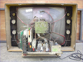 V systems is reflected in its subdivision into largely independent functional blocks, with the possibility having special data-bus structures. It is useful to divide the structure into a data-oriented flow and control-oriented flow, so that we have four main groups of components:
V systems is reflected in its subdivision into largely independent functional blocks, with the possibility having special data-bus structures. It is useful to divide the structure into a data-oriented flow and control-oriented flow, so that we have four main groups of components:
1.- The control unit and peripherals, based on well-known microprocessor structures, with a central communication bus for flexibility and ease to use. An arrangement around a central bus makes it possible to easily expand the system constantly and thereby add on further quality-enhancing and special functions for the picture, text and/or sound processing at no great expense. A non-volatile storage element, in which the factory settings are stored, is associated to this control processor.
2.- The video functions are mainly the video signal processing and some additional features like for example deflection, a detailed description follows in the paper. However, the key point for VLSI implementations is a well-organized definition of the macro-blocks. This serves to facilitate interconnection of circuit components, and minimizes power consumption, which can be considerable at the processor speeds needed.
3.- The digital concept facilitates the decoding of today’s new digital sound broadcasting standards as well as the input of external signal sources, such as Digital Audio Tape (DAT) and Compact Disk (CD). Programmability permits mono, stereo, and multilingual broadcasts; the compatibility with other functions in the TV system is resolved with the common communication bus. This leads us to part two which is dedicated to the description of this problem.
4.- With a digital system, it is possible to add some special or quality-enhancing functions simply by incorporating a single additional macro-function or chip. Therefore, standards are no longer so important due to the high level of adaptability of digital solutions. For example adaptation to a 16:9 picture tube is easy.
II. DIGITIZATION OF "TV FUNCTIONS"
The idea of digitization of TV functions is not new. The time some companies have started to work on it, silicon technology was not really adequate for the needed computing power so that the most effective solutions were full custom designs. This forced the block-oriented architecture where the digital functions introduced were the one to one replacement of an existing analog function. In Figure 2 there is a simplified representation of the general concept.

Fig.2: Block Diagram of first generation digital TV set
The natural separation of video and audio resulted in some incompatibilities and duplication of primary functions. The emitting principle is not changed, redundancy is a big handicap, for example the time a SECAM channel is running, the PAL functions are not in operation. New generations of digital TV systems should re-think the whole concept top down before VLSI system partitioning.
In today’s state-of-the-art solution one can recognize all the basic functions of the analog TV set with, however, a modularity in the concept, permitting additional features becomes possible, some special digital possibilities are exploited, e.g. storage and filtering techniques to improve signal reproduction (adaptive filtering, 100 Hz technology), to integrate special functions (picture-in-picture, zoom, still picture) or to receive digital broadcasting standards (MAC, NICAM). The Figure 3 shows the ITT Semiconductors solution which was the first on the market in 1983 !! !!

Fig.3: The DIGIT2000 TV receiver block diagram
Description:This invention relates generally to digital television receivers and, particularly, to digital television receivers arranged for economical interfacing with a plurality of auxiliary devices.
With the proliferation of low cost microprocessors and microprocessor controlled devices, television (TV) receivers are being designed to utilize digitized signals and controls. There are many advantages associated with digital TV receivers, including uniformity of product, precise control of signal parameters and operating conditions, elimination of mechanical switches and a potential for reliability that has been heretofore unknown. Digital television receivers include a high speed communication bus for interconnecting a central control unit microprocessor (CCU) with various TV function modules for processing a TV signal. These modules include a deflection processing unit (DPU), a video processing unit (VPU), an automatic phase control (APC), a video codec unit (VCU), an audio analog to digital converter (ADC) and an audio processing unit (APU). The CCU has associa
ted with it a non-volatile memory, a hardware-generated clock signal source and a suitable interface circuit for enabling the CCU to control processing of the TV signal throughout the various TV function modules. The received TV signal is in analog form and suitable analog to digital (A/D) converters and digital to analog (D/A) converters are provided for converting the digital and analog signals for signal processing and for reconverting them after processing for driving a cathode ray tube (CRT) and suitable speakers. The CCU microprocessor is heavily burdened because of the high speed timing required to control the various TV function modules. To further complicate matters, modern TV receivers are increasingly being used with auxiliary devices for other than simple processing of TV signals. For example, the video cassette recorder (VCR) has enabled so-called "time-shifting" of program material by recording TV signals for later, more convenient viewing. The VCR is also extensively used with prerecorded material and with programs produced by users having access to a video camera. Other auxiliary devices providing features such as "Space Phone" whereby the user is enabled to make and receive telephone calls through his TV receiver, are desirable options. Additionally, a source selector auxiliary device enables a host of different signal sources, such as cable, over-the-air antenna, video disk, video games, etc. to be connected for use with the signal processing circuitry of the TV. In addition, all of these many auxiliary devices are preferably controllable from a remote position. A great deal of flexibility is available since each of the above auxiliary devices includes a microprocessor for internally controlling fu
nctioning of the device. In the digital TV system described, the CCU microprocessor and the microprocessors in the auxiliary devices may be conventionally arranged to communicate over the main communication bus. Such a system would entail a specialized microprocessor with a hardware-generated clock signal in each auxiliary device in order to communicate at the high speeds used on the main communication bus. A specialized microprocessor, that is, one that is hardware configured, is significantly more expensive than an off-the-shelf microprocessor. Also, the auxiliary devices may not be required, or even desired, by all users and their low volume production cost becomes very important. It would therefore be desirable to provide a digital TV in which such auxiliary devices utilized off-the-shelf microprocessors for their control.
A digital TV system includes a CCU that is interconnected by a three-wire, high speed bus to a plurality of TV signal function modules for controlling operation thereof by means of a high speed hardware generated clock signal. A software generated clock signal in the CCU is supplied on a low speed two-wire auxiliary device bus which is connected to microprocessors in a plurality of auxiliary devices for performing functions ancillary to TV signal processing. The microprocessor in each auxiliary device is an off-the-shelf type that does not require any special hardware because the timing on the auxiliary device bus is sufficiently slow to enable software monitoring of the line and data transfer.
As mentioned, the three-wire IM bus 21 is a high speed bidirectional bus in which CCU 20 functions as the master and all of the interconnected TV signal processing function modules are slaves that communicate with the CC
U in accordance with the protocol established for the system. CCU 20 is also indicated as including a software generated clock which supplies a two-wire auxiliary device bus 50. Two-wire bus 50 includes a clock lead 51 and a data lead 52 coupled to a plurality of auxiliary devices. A VCR 54, including an off-the-shelf microprocessor 55, is coupled to bus 50. A Source Selector 56, including an off-the-shelf microprocessor 57, is also coupled to bus 50. Source Selector 56 has access to four RF inputs, two baseband video and audio inputs and one separate baseband audio input. It will be appreciated that Source Selector 56 may have a greater or lesser number of signal sources to which it has access. Source Selector 56 outputs are coupled to VCR 54 and also to tuner 10 and supply, under control of CCU 20 and keyboard 44, the signal from the signal source selected by keyboard 44 or IR transmitter 46 for use with the digital TV. Auxiliary device bus 50 is also coupled to a Space Phone 58 which includes an off-the-shelf microprocessor 59 and a modem 60 that is connectable to a conventional telephone terminal. Two-wire auxiliary device bus 50 is a relatively low speed bus and there is no need for separate hardware generated clock signals to be developed by the auxiliary device microprocessors. As mentioned above, this feature involves a significant savings in the cost and complexity of the auxiliary devices.
The protocol used on the two-wire auxiliary device bus consists of a 16 bit sequence, the first eight bits of which are used for bus address commands for the auxiliary devices. Each auxiliary device may respond to 16 addresses which allows the CCU to write into or read from various storage registers in the devices which are used for control or data storage. Thus, with this low cost system, as many as 16 auxiliary devices may be connected to the auxiliary device bus. The second eight bits of the 16 bit sequence contain data which is either transferred from the CCU to the auxiliary device addressed, or transferred from the auxiliary device to the CCU, based upon the bus address used. Thus, the various bus addresses to which a given auxiliary device will respond determine whether the auxiliary device will receive data from the CCU or send data to the CCU. The clock line timing, generated by software in CCU 20, is slow enough to permit software monitoring of the line and data reception by simple auxiliary device microprocessors that are not equipped with an external interrupt feature. The timing on the auxiliary device bus is made sufficiently fast to avoid too many instruction steps or the need for special registers in CCU 20. In the system described, data is clocked every 82.5 microseconds, thus permitting a 16 bit word to be clocked in 1.32 milliseconds. A pause of 277.5 microseconds between the first 8 bits and the second 8 bits permits the slave auxiliary device to process the bus address data contained in the first 8 bits. This timing fits into the 2 millisecond timing block structure used for the CCU in controlling the DIGIT 2000 digital TV. Two-2 millisecond timing blocks have been established in the CCU, which has a 20 millisecond timing loop divided into ten-2 millisecond timing blocks. Thus, two control words may be sent to an auxiliary device every 20 milliseconds, or a request by the CCU to receive data and the actual receipt of that data may take place in that time period.

Referring to the drawing, a digital TV includes a tuner 10 coupled to an IF/Detector 12 which has a pair of outputs 13 and 14 supplying video and audio signals, respectively. Control signals for tuner 10 are supplied through an interface circuit 16 from a CCU microprocessor 20 which functions as a single master control unit for the system. Microprocessor 20 is interconnected by means of a bidirectional three-wire IM (Intermetal) bus 21 to a DPU 22, a VPU 26, an APC 30, a TTX (teletext processor) 38, an APU 36, an ADC 32 and a non-volatile memory 24. A serial control line 29 interconnects a hardware generated clock 28, VPU 26 and VCU 34. VPU 26 and VCU 34 are also interconnected by a seven wire cable and TTX 38 is interconnected with a DRAM 42. DRAM 42 is a dynamic RAM in which TTX information is stored for display. VCU 34 is supplied with video signal and supplies a digitized 7 bit grey coded video signal to VPU 24 for processing and RGB color signals to a Video Drive 40 which, in turn, supplies a cathode ray tube (not shown). A keyboard 44 is coupled to CCU 20 and includes an IR detector that is responsive to coded IR signals supplied from an IR transmitter (IRX) 46. A resident microprocessor in keyboard 44 decodes the received IR signals and generated control commands and supplies appropriate outputs to CCU 20. The diagram, as described, is substantially identical to that for a "DIGIT" 2000 VLSI Digital TV System developed by ITT Intermetal and published in Edition 1984/85 Order No. 6250-11-2E
--------------------------
By its very nature, computer technology is digital, while consumer electronics are geared to the analog world. Starts have been made only recently to digitize TV and radio broadcasts at the transmitter end (in form of DAB, DSR, D2-MAC, NICAM etc). The most difficult technical tasks involved in the integration of different media are interface matching and data compression [5].
After this second step in the integration of multimedia signals, an attempt was made towards standardization, namely, the integration of 16 identical high speed processors with communication and programmability concepts comprised in the architecture !
Many solutions proposed today (for MPEG 1 mainly) are derived from microprocessor architectures or DSPs, but there is a gap between today’s circuits and the functions needed for a real fully HDTV system. The AT&T hybrid codec [29], for instance, introduces a new way to design multimedia chips by optimizing the cost of the equipment considering both processing and memory requirements.
The concept is to provide generic architectures that can be applied to a wide variety of systems taking into account that certain functions have to be optimized and that some other complex algorithms have to be ported to generic processors.
Basics of current video coding standards
Compression methods take advantage of both data redundancy and the non-linearity of human vision. They exploit correlation in space for still images and in both space and time for video signals. Compression in space is known as intra-frame compression, while compression in time is called inter-frame compression. Generally, methods that achieve high compression ratios (10:1 to 50:1 for still images and 50:1 to 200:1 for video) use data approximations which lead to a reconstructed image not identical to the original.
Methods that cause no loss of data do exist, but their compression ratios are lower (no better than 3:1). Such techniques are used only in sensitive applications such as medical imaging. For example, artifacts introduced by a lossy algorithm into a X-ray radiograph may cause an incorrect interpretation and alter the diagnosis of a medical condition. Conversely, for commercial, industrial and consumer applications, lossy algorithms are preferred because they save storage and communication bandwidth.
Lossy algorithms also generally exploit aspects of the human visual system. For instance, the eye is much more receptive to fine detail in the luminance (or brightness) signal than in the chrominance (or color) signals. Consequently, the luminance signal is usually sampled at a higher spatial resolution. Second, the encoded representation of the luminance signal is assigned more bits (a higher dynamic) than are the chrominance signals. The eye is less sensitive to energy with high spatial frequency than with low spatial frequency [7]. Indeed, if the images on a personal computer monitor were formed by an alternating spatial signal of black and white, the human viewer would see a uniform gray instead of the alternating checkerboard pattern. This deficiency is exploited by coding the high frequency coefficients with fewer bits and the low frequency coefficients with more bits.
All these techniques add up to powerful compression algorithms. In many subjective tests, reconstructed images that were encoded with a 20:1 compression ratio are hard to distinguish from the original. Video data, even after compression at ratios of 100:1, can be decompressed with close to analog videotape quality.
Lack of open standards could slow the growth of this technology and its applications. That is why several digital video standards have been proposed:
- JPEG (Joint Photographic Expert Group) for still pictures coding
- H.261 at p times 64 kbit/s was proposed by the CCITT (Consultative Committee on International Telephony and Telegraphy) for teleconferencing
- MPEG-1 (Motion Picture Expert Group) up to 1,5 Mbit/s was proposed for full motion compression on digital storage media
- MPEG-2 was proposed for digital TV compression, the bandwith depends on the chosen level and profile [33].
Another standard, the MPEG-4 for very low bit rate coding (4 kbit/s up to 64 kbit/s) is currently being debated.
Digitalization of the fundamental TV functions is of great interest since more than 30 years. Several million of TV sets have been produced containing digital systems. However, the real and full digital system is for the future. A lot of work is done in this field today, the considerations are more technical than economical which is a normal situation for an emerging technology. The success of this new multimedia technology will be given by the applications running with this techniques.
The needed technologies and methodologies were discussed to emphasize the main parameters influencing the design of VLSI chips for Digital TV Applications like parallelization, electrical constraints, power management, scalability and so on...............................
ITT NOKIA DIGIVISION 7170 VT CHASSIS DIGI B-E Power supply circuit description ITT DIGIVISION CHASSIS DIGI B-E:
 After Pressing the_ON/OFF button
A d.c. voltage is passed from the bridge rectifier via D 715 to
Pin 16 of IC 710 (Fig. 28).
When the voltage reaches a level of 9 V, a switch inside the IC
will switch on the IC (see Figs. 29 and 32).
Capacitor C 710 is now charged to about 1 V with a large
current. Once this value has been reached, control pulses
(narrow at first, and then wider in dependence on the voltage at
Pin 10, which is the charging voltage of C 710), are outputted at
Pin 14, until about 1.8 V are reached at Pin 10. Ft 719
determines the maximum pulsewidth at the end of the start
phase.
In the case of voltages above approx. 1.8 V, no more control
pulses are generated by TDA 2165. From this point onwards,
control pulses must be available at Pin 6, otherwise stan-up will
be re-attempted after approx. 100 ms. These periodical start-up
attempts are cl
early audible, and indicate that no pulses arereaching Pin 6 of IC TEA 2165 from IC 740, TEA 2170 orTSA
0416 (Pin 1).
In the unsynchronized phase (no pulses at Pin 6 of IC 710), all
output voltages are approx. 25 % of the set-point values.
Example: U I only approx. 35 V instead of 145 V. Voltage UV"
is an exception here. This voltage is available at
almost its full level, since it is obtained during the
conducting phase of the switching transistor.
Supply voltage IC 740
In the start-up phase, voltage VV" (8 V) is available immediately.
VV" is also used as an operating voltage at Pin 2 during
switched-on status.
Oscillator with start program of IC 710
The sawtooth oscillator oscillates at a basic frequency of
approx. 14.6 kHz, which is determined by components Fl 717
and C 718. Its frequency, in conjunction with the start program,
sen/es during the start-up phase as an actuation signal for
switching transistorT 731.
As long as there are no control pulses being received at Pin 6,
the oscillator is switched on and off periodically, with the
oscillating frequency in ON state measuring 14.6 kHz (see also
Fig. 31). As soon as line-frequency needle pulses appear at Pin
6 of IC 710, the oscillator is synchronized to line frequency via a
start-stop flip-flop, and oscillates continuously, but is no longer
utilized for obtaining the control pulse at Pin 14. The information
from the start-stop flip-flop is now passed directly to the driver !
ITT NOKIA DIGIVISION 7170 VT CHASSIS DIGI B-E Function of the Stand-By Circuit
In set stand-by mode, the approx. 3.5 ps narrow on/off pulses
are fed from TSA 0416 via pulse transformer Tr. 751 to
TEA 2165. This causes all output voltages of the transformer
power pack to be reduced to approx. 1/6 of their normal levels.
Voltage VV", however, is only slightly altered in comparison with
normal operation, since this voltage is not obtained from the
blocking phase of the switching transistor, but from the
conducting phase, due to the reverse polarity of D 790 in
relation to D 782 (see Fig. 33). This ensures that power supply
TSA 0416 (from VV", 8 V) and DPU (5 V, Vvm) can be supplied
with operating voltage during stand-by mode.
Switch-over of the output pulsewidth is
performed at Pin 7 ofTSA 0416. When the mains switch is set to ON, a Low passes
to Pin 7 of IC 740 (TSA 0416) via mains switch S 1401/AZ 12
1505/D 741/Fi 745. This reduces the negative feedback of the
lower difference amplifier. At the same time, the pulsewidth ratio
at Pin 1 of TSA 0416 also alters. In stand-by mode it measures
approx. 3 ps, and in normal operating mode approx. 30 us.
When switched from stand-by to normal operating mode by the
remote control, the CCU/IC 1520 puts the requisite low at Pin 5.
http://old-digital-television.blogspotcom/
Driver Circuit- IC 710 /TEA 2165
The driver circuit obtains the necessary current from Pin 15,
with the majority of the power being taken from the switching
transformer via D 722.
Diodes D 730, 731, 731 ensure the requisite clearing function of
the switching transistor. They clamp Pins 5, 4, 12 and 13 to
approx. minus 2.1 V against ground. This produces a negative
content of approx. -2 V at the control pulse at Pin 14 as well.
A short circuit at one of the 3 diodes D 730-325 reduces the
negative voltage at Pins 5, 4, 12 and 13, or the negative content
at Pin 14. This results in a higher power dissipation at T 731,
which sooner or later will destroy the transistor.
ITT NOKIA DIGIVISION 7170 VT CHASSIS DIGI B-E TEA2164 /2165 SWITCH MODE POWER SUPPLY PRIMARY CIRCUIT:
.POSITIVE AND NEGATIVE OUTPUT CURRENT
UP TO 1.2AAND – 1.7A .A TWO LEVEL COLLECTOR CURRENT LIMITATION
.COMPLETE TURN OFF AFTER LONG DURATION
OVERLOADS .UNDER AND OVER VOLTAGELOCK-OUT .SOFT START BY PROGRESSIVE CURRENT
LIMITATION .DOUBLE PULSE SUPPRESSION .BURST MODE OPERATION UNDER STANDBY
CONDITIONS
DESCRIPTION

In amaster slave architecture, the TEA2164control
IC achieves the slave function. Primarily designed
for TV receivers and monitors applications, this
circuit provides an easy synchronizationand smart
solution for low power stand by operation.
Located at the primary side the TEA2164 Control
IC ensures :
- the power supply start-up
- the power supply control under stand-by conditions
- the process of the regulation signals sent by the
master circuit located at the secondary side
- directbasedrive of the bipolarswitching transistor
- the protection of the transistor and the power
supply under abnormal conditions.
II. GENERAL DESCRIPTION
In a master slave architecture, the TEA2164 Control
IC, located at the primary side of an off line
power supply achievesthe slave function ;whereas
the master circuit is located at the secondary side.
The link between both circuits is realized by a small
pulse transformer

In the operation of the master-slave architecture,
four majors cases must be considered :
- normal operating
- stand-bymode
- power supply start-up
- abnormal conditions : off load, short circuit, ...
II.1. Normal Operating (master slave mode)
In this configuration, the master circuit generatesa
pulse widthmodulatedsignal issued from themonitoring
of the output voltage which needs the best
accuracy (in TV applications : the horizontal deflection
stagesupplyvoltage).Themaster circuit power
supply can be supplied by another output.
The PWM signal are sent towards the primary side
through small differentiating transformer. For the
TEA2164 positive pulses are transistor switchingon
commands ; and negative pulses are transistor
switching-offcommands (Figure 4). In this configuration,
only by synchronizing the master oscillator,
the switching transistor may be synchronized with
an external signal.
II.2. Stand-by Mode
In this configuration the master circuit no longer
sends PWM signals, the structure is not synchronized
; and the TEA2164 operates in burst mode.
The average power consumption at the secondary
side may be very low 1W 3 P 3 6W (as it is
consumed in TV set during stand by).
By action on the maximum duty cycle control, a
primary loop maintains a semi-regulation of the
output voltages.Voltage on feed-back is applied on
Pin 9.
Burst period is externally programmedby capacitor
C1.
II.3. Power Supply Start-up
After the mains have been switched-on, the VCC
storage capacitor of the TEA2164 is charged
through a high value resistor connected to the
rectified high voltage.When Vcc reaches VCC start
threshold (9V typ), the TEA2164 starts operatingin
burst mode. Since available output power is low in
burst mode the output power consumption must
remain low before complete setting-up of output
voltage. In TV application it can be achieved by
maintaining the TV in stand-by mode during startup.
Overvoltage Protection
When VCC exceeds VCC max, an internal flip-flop
stops output conduction signals. The circuit will
start again after the capacitor C1 discharge ; it
means : after loss of synchronization or after Vcc
stop crossing (Figure 7).
In flyback converters, this function protects the
power supply against output voltage runaway.
ITT NOKIA DIGIVISION 7170 VT CHASSIS DIGI B-E Synchronized switch-mode power supply:
In a switch mode power supply, a first switching transistor is coupled to a primary winding of an isolation transformer. A second switching transistor periodically applies a low impedance across a second winding of the transformer that is coupled to an oscillator for synchronizing the oscillator to the horizontal frequency. A third winding of the transformer is coupled via a switching diode to a capacitor of a control circuit for developing a DC control voltage in the capacitor that varies in accordance with a supply voltage B+. The control voltage is applied via the transformer to a pulse width modulator that is responsive to the oscillator output signal for producing a pulse-width modulated control signal.
The control signal is applied to a mains coupled chopper transistor for generating and regulating the supply voltage B+ in accordance with the pulse width modulation of the control signal.Description:
The invention relates to switch-mode power supplies.
Some television receivers have signal terminals for receiving, for example, external video input signals such as R, G and B input signals, that are to be developed relative to the common conductor of the receiver. Such signal terminals and the receiver common conductor may be coupled to corresponding signal terminals and common conductors of external devices, such as, for example, a VCR or a teletext decoder.
To simplify the coupling of signals between the external devices and the television receiver, the common conductors of the receiver and of the external devices are connected together so that all are at the same potential. The signal lines of each external device are coupled to the corresponding signal terminals of the receiver. In such an arrangement, the common conductor of each device, such as of the television receiver, may be held "floating", or conductively isolated, relative to the corresponding AC mains supply source that energizes the device. When the common conductor is held floating, a user touching a terminal that is at the potential of the common conductor will not suffer an electrical shock.
Therefore, it may be desirable to isolate the common conductor, or ground, of, for example, the television receiver from the potentials of the terminals of the AC mains supply source that provide power to the television receiver. Such isolation is typically achieved by a transformer. The isolated common conductor is sometimes referred to as a "cold" ground conductor.
In a typical switch mode power supply (SMPS) of a television receiver the AC mains supply voltage is coupled, for example, directly, and without using transformer coupling, to a bridge rectifier. An unregulated direct current (DC) input supply voltage is produced that is, for example, referenced to a common conductor, referred to as "hot" g
round, and that is conductively isolated from the cold ground conductor. A pulse width modulator controls the duty cycle of a chopper transistor switch that applies the unregulated supply voltage across a primary winding of an isolating flyback transformer. A flyback voltage at a frequency that is determined by the modulator is developed at a secondary winding of the transformer and is rectified to produce a DC output supply voltage such as a voltage B+ that energizes a horizontal deflection circuit of the television receiver. The primary winding of the flyback transformer is, for example, conductively coupled to the hot ground conductor. The secondary winding of the flyback transformer and voltage B+ may be conductively isolated from the hot ground conductor by the hot-cold barrier formed by the transformer.It may be desirable to synchronize the operation of the chopper transistor to horizontal scanning frequency for preventing the occurrence of an objectionable visual pattern in an image displayed in a display of the television receiver.
It may be further desirable to couple a horizontal synchronizing signal that is referenced to the cold ground to the pulse-width modulator that is referenced to the hot ground such that isolation is maintained.
A synchronized switch mode power supply, embodying an aspect of the invention, includes a transfromer having first and second windings. A first switching arrangement is coupled to the first winding f
or generating a first switching current in the first winding to periodically energize the second winding. A source of a synchronizing input signal at a frequency that is related to a deflection frequency is provided. A second switching arrangement responsive to the input signal and coupled to the second winding periodically applies a low impedance across the energized second winding that by transformer action produces a substantial increase in the first switching current. A periodic first control signal is generated. The increase in the first switching current is sensed to synchronize the first control signal to the input signal. An output supply voltage is generated from an input supply voltage in accordance with the first control signal.ITT NOKIA DIGIVISION 7170 VT CHASSIS DIGI B-E Switch-mode power supply with burst mode standby operation:
In a switch mode power supply, a first switching transistor is coupled to a primary winding of a transformer for generating pulses of a switching current. A secondary winding of the transformer is coupled via a switching diode to a capacitor of a control circuit for developing a control signal in the capacitor. The control signal is applied to a mains coupled chopper second transistor for generating and regulating supply voltages in accordance with pulse width modulation of the control signal. During standby operation, the first and second transistors operate in a burst mode that is repetitive at a frequency of the AC mains supply voltage such as 50 Hz. In the burst mode operation, during intervals in which pulses of the switching current occur, the pulse width and peak amplitude of the switching current pulses progressively increase in accordance with the waveform of the mains supply voltage to provide a soft start operation in the standby mode of operation within each burst group.Description:
The invention relates to switch-mode power supplies.
In a typical switch mode power supply (SMPS) of a television receiver the AC mains supply voltage is coupled to a bridge rectifier. An unregulated direct current (DC) input supply voltage is produced. A pulse width modulator controls the duty cycle of a chopper transistor switch that applies the unregulated supply voltage across a primary winding of a flyback transformer. A flyback voltage at a frequency that is determined by the modulator is developed at a secondary winding of the transformer and is rectified to produce DC output supply voltages such as a voltage B+ that energizes a horizontal deflection circuit of the television receiver and a voltage that energizes a remote control unit.
During normal operation, the DC output supply voltages are regulated by the pulse width modulator in a negative feedback manner. During standby operation, the SMPS is required to generate the DC output supply voltage that energizes the remote control unit. However, most other stages of the television receiver are inoperative and do not draw supply currents. Consequently, the average value of the duty cycle of the chopper transistor may have to be substantially lower during standby than during normal operation.
Because of, for example, storage time limitation in the chopper transistor, it may not be possible to reduce the length of the conduction interval in a given cycle below a minimum level. Thus, in order to maintain the average value of the duty cycle low, it may be desirable to operate the chopper transistor in an intermittent or burst mode, during standby. During standby, a long dead time interval occurs between consecutively occurring burst mode operation intervals. Only during the burst mode operation interval switc
hing operation occurs in the chopper transistor. The result is that each of the conduction intervals is of a sufficient length.In accordance with an aspect of the invention, burst mode operation intervals are initiated and occur at a rate that is determined by a repetitive signal at the frequency of the AC mains supply voltage. For example, when the mains supply voltage is at 50 Hz, each burst mode operation interval, when switching cycles occur, may last 5 milliseconds and the dead time interval when no switching cycles occur, may last during the remainder portion or 15 milliseconds. Such arrangement that is triggered by a signal at the frequency of the mains supply voltage simplifies the design of the SMPS.
The burst mode operation intervals that occur in standby operation are synchronized to the 50 Hz signal. During each such interval, pulses of current are produced in transformers and inductances of the SMPS. The pulses of current occur in clusters that are repetitive at 50 Hz. The pulses of current occur at a frequency that is equal to the switching frequency of the chopper transistor within each burst mode operation interval. Such qurrent pulses might produce an objectionable sound during power-off or standby operation. The objectionable sound might be produced due to possible parasitic mechanical vibrations as a result of the pulse currents in, for example, the inductances and transformers of the SMPS.
In accordance with another aspect of the invention, the change in the AC mains supply voltage during each period causes the length of the conduction interval in consecutively occurring switching cycle during the burst mode operation interval to increase progressively. Such operation that occurs during each burst mode operation interval may be referred to as soft start operation. The soft start operation causes, for example, gradual charging of capacitors in the SMPS. Consequently, the parasitic mechanical vibrations are substantially reduced. Also, the frequency of the switching cycles within each burst mode operation interval is maintained above the audible range for further reducing the level of such audible noise during standby operation.
A switch mode power supply, embodying an aspect of the invention, for generating an output supply voltage during both a standby-mode of operation and during a run-mode of operation includes a source of AC mains input supply voltage. A control signal at a given frequency is generated. A switching arrangement energized by the input supply voltage and responsive to the first control signal produces a switching current during both the standby-mode of operation and the run-mode operation. The output supply voltage is generated from the switching current. An arrangement coupled to the switching arrangement and responsive to a standby-mode/run-mode control signal and to a signal at a frequency that is determined by a frequency of the AC mains input supply voltage controls the switching arrangement in a burst mode manner during the standby-mode of operation. During a burst interval, a plurality of switching cycles are performed and during an alternating dead time interval no switching cycles are performed. The two intervals alternate at a frequency that is determined by the frequency of the AC mains input supply voltage.
ITT NOKIA DIGIVISION 7170 VT CHASSIS DIGI B-E CIRCUIT ARRANGEMENT IN A PICTURE DISPLAY DEVICE UTILIZING A STABILIZED SUPPLY VOLTAGE CIRCUIT:
Line synchronized switch mode power supply:

A stabilized supply voltage circuit for a picture display device comprising a chopper wherein the switching signal has the line frequency and is duration-modulated. The coil of the chopper constitutes the primary winding of a transformer a secondary winding of which drives the line output transistor so that the switching transistor of the chopper also functions as a driver for the line output stage. The oscillator generating the switching signal may be the line oscillator. In a special embodiment the driver and line output transistor conduct simultaneously and in order to limit the base current of the line output transistor a coil shunted by a diode is incorporated in the drive line of the line output transistor. Other secondary windings of the transformer drive diodes which conduct simultaneously with the efficiency diode of the chopper so as to generate further stabilized supply voltages.

1. An electrical circuit arrangement for a picture display device operating at a given line scanning frequency, comprising a source of unidirectional voltage, an inductor, first switching transistor means for periodically energizing said inductor at said scanning frequency with current from said source, an electrical load circuit coupled to said inductor and having applied thereto a voltage as determined by the ratio of the ON and OFF periods of said transistor, means for maintaining the voltage across said load circuit at a given value comprising means for comparing the voltage of said load circuit with a reference voltage, means responsive to departures of the value of the load circuit voltage from the value of said reference voltage for varying the conduction ratio of the ON and OFF periods of said transistor thereby to stabilize said load circuit voltage at the given value, a line deflection coil system for said picture display device, means for energizing said line deflection coil system from said load voltage circuit means, means for periodically interrupting the energization of said line deflection coil comprising second switching means and means coupled to said inductor for deriving therefrom a switching current in synchronism with the energization periods of said transistor and applying said switching current to said switching means thereby to actuate the same, and means coupled to said switching means and to said load voltage circuit for producing a voltage for energizing said 2. A circuit as claimed in claim 1 wherein the duty cycle of said switching 3. A circuit as claimed in claim 1 further comprising an efficiency first 4. A circuit as claimed in claim 3 further comprising at least a second diode coupled to said deriving means and to ground, and being poled to 5. A circuit as claimed in claim 1 wherein said second switching means comprises a second transistor coupled to said deriving means to conduct simultaneously with said first transistor, and further comprising a coil coupled between said driving means and said second transistor and a third diode shunt coupled to said coil and being poled to conduct when said 6. A circuit as claimed in claim 1 further comprising a horizontal oscillator coupled to said first transistor, said oscillator being the 7. A circuit as claimed in claim 1 further comprising means coupled to said inductor for deriving filament voltage for said display device.
Description:
The invention relates to a circuit arrangement in a picture display device wherein the input direct voltage between two input terminals, which is obtained be rectifying the mains alternating voltage, is converted into a sta bilized output direct voltage by means of a switching transistor and a coil and wherein the transistor is connected to a first input terminal and an efficiency diode is connected to the junction of the transistor and the coil. The switching transistor is driven by a pulsatory voltage of line frequency which pulses are duration-modulated in order to saturate the switching transistor during part of the period dependent on the direct voltage to be stabilized and to cut off this transistor during the remaining part of the period. The pulse duration modulation is effected by means of a comparison circuit which compares the direct voltage to be stabilized with a substantially constant voltage, the coil constituting the primary winding of a transformer.
Such a circuit arrangement is known from German "Auslegeschrift" 1.293.304. wherein a circuit arrangement is described which has for its object to convert an input direct voltage which is generated between two terminals into a different direct voltage. The circuit employs a switch connected to the first terminal of the input voltage and periodically opens and closes so that the input voltage is converted into a pulsatory voltage. This pulsatory voltage is then applied to a coil. A diode is arranged between the junction of the switch and the coil and the second terminal of the input voltage whilst a load and a charge capacitor in parallel thereto are arranged between the other end of the coil and the second terminal of the input voltage. The assembly operates in accordance with the known efficiency principle i.e., the current supplied to the load flows alternately through the switch and through the diode. The function of the switch is performed by a switching transistor which is driven by a periodical pulsatory voltage which saturates this transistor for a given part of the period. Such a configuration is known under diff erent names in the literature; it will be referred to herein as a "chopper." A known advantage thereof, is that the switching transistor must be able to stand a high voltage or provide a great current but it need not dissipate a great power. The output voltage of the chopper is compared with a constant reference voltage. If the output voltage attempts to vary because the input voltage and/or the load varies, a voltage causing a duration modulation of the pulses is produced at the output of the comparison arrangement. As a result the quantity of the energy stored in the coil varies and the output voltage is maintained constant. In the German "Auslegeschrift" referred to it is therefore an object to provide a stabilized supply voltage device.
In the circuit arrangement according to the mentioned German "Auslegeschrift" the frequency of the load variations or a harmonic thereof is chosen as the frequency for the switching voltage. Particularly when the load fed by the chopper is the line deflection circuit of a picture display device, wherein thus the impedance of the load varies in the rhythm of the line frequency, the frequency of the switching voltage is equal to or is a multiple of the line frequency.
 It is to be noted that the chopper need not necessarily be formed as that in the mentioned German "Auslegeschrift." In fact, it is known from literature that the efficiency diode and the coil may be exchanged. It is alternatively possible for the coil to be provided at the first terminal of the input voltage whilst the switching transistor is arranged between the other end and the second terminal of the input voltage. The efficiency diode is then provided between the junction of said end and the switching transistor and the load. It may be recognized that for all these modifications a voltage is present across the connections of the coil which voltage has the same frequency and the same shape as the pulsatory switching voltage. The control voltage of a line deflection circuit is a pulsatory voltage which causes the line output transistor to be saturates and cut off alternately. The invention is based on the recognition that the voltage present across the connections of the coil is suitable to function as such a control voltage and that the coil constitutes the primary of a transformer. To this end the circuit arrangement according to the invention is characterized in that a secondary winding of the transformer drives the switching element which applies a line deflection current to line deflection coils and by which the voltage for the final anode of a picture display tube which forms part of the picture display device is generated, and that the ratio between the period during which the switching transistor is saturated and the entire period, i.e., the switching transistor duty cycle is between 0.3 and 0.7 during normal operation.
The invention is also based on the recognition that the duration modulation which is necessary to stabilize the supply voltage with the switching transistor does not exert influence on the driving of the line output transistor. This resides in the fact that in case of a longer or shorter cut-off period of the line output transistor the current flowing through the line deflection coils thereof is not influenced because of the efficiency diode current and transistor current are taken over or, in case of a special kind of transistor, the collector-emitter current is taken over by the base collector current and conversely. However, in that case the above-mentioned ratios of 0.3 : 0.7 should be taken into account since otherwise this take-over principle is jeopardized.
As will be further explained the use of the switching transistor as a driver for the line output transistor in an embodiment to be especially described hereinafter has the further advantage that the line output transistor automatically becomes non-conductive when this switching transistor is short circuited so that the deflection and the EHT for the display tube drop out and thus avoid damage thereof.
Due to the step according to the invention the switching transistor in the stabilized supply functions as a driver for the line deflection circuit. The circuit arrangement according to the invention may in addition be equipped with a very efficient safety circuit so that the reliability is considerably enhanced, which is described in the U.S. Pat. No. 3,629,686. The invention is furthermore based on the recognition of the fact that the pulsatory voltage present across the connections of the coil is furthermore used and to this end the circuit arrangement according to the invention is characterized in that secondary windings of the transformer drive diodes which conduct simultaneously with the efficiency diode so as to generate further stabilized direct voltages, one end of said diodes being connected to ground.
In order that the invention may be readily carried into effect, a few embodiments thereof will now be described in detail by way of example with reference to the accompanying diagrammatic drawings in which:
FIG. 1 shows a principle circuit diagram wherein the chopper and the line deflection circuit are further shown but other circuits are not further shown.
FIGS. 2a, 2b and 2c show the variation as a function of time of two currents and of a voltage occurring in the circuit arrangement according to FIG. 1.
FIGS. 3a 3b, 3c and 3d show other embodiments of the chopper.
FIGS. 4a and 4b show modifications of part of the circuit arrangement of FIG. 1.
 In FIG. 1 the reference numeral 1 denotes a rectifier circuit which converts the mains voltage supplied thereto into a non-stabilized direct voltage. The collector of a switching transistor 2 is connected to one of the two terminals between which this direct voltage is obtained, said transistor being of the npn-type in this embodiment and the base of which receives a pulsatory voltage which originates through a control stage 4 from a modulator 5 and causes transistor 2 to be saturated and cut off alternately. The voltage waveform 3 is produced at the emitter of transistor 2. In order to maintain the output voltage of the circuit arrangement constant, the duration of the pulses provided is varied in modulator 5. A pulse oscillator 6 supplies the pulsatory voltage to modulator 5 and is synchronized by a signal of line frequency which originates from the line oscillator 6' present in the picture display device. This line oscillator 6' is in turn directly synchronized in known manner by pulses 7' of line frequency which are present in the device and originate for example from a received television signal if the picture display device is a television receiver. Pulse oscillator 6 thus generates a pulsatory voltage the repetition frequency of which is the line frequency.
The emitter of switching transistor 2 is connected at one end to the cathode of an efficiency diode 7 whose other end is connected to the second input voltage terminal and at the other end to primary winding 8 of a transformer 9. Pulsatory voltage 3 which is produced at the cathode of efficiency diode 7 is clamped against the potential of said second terminal during the intervals when this diode conducts. During the other intervals the pulsatory voltage 3 assumes the value V i . A charge capacitor 10 and a load 11 are arranged between the other end of winding 8 and the second input voltage terminal. The elements 2,7,8,10 and 11 constitute a so-called chopper producing a direct voltage across charge capacitor 10, provided that capacitor 10 has a sufficiently great value for the line frequency and the current applied to load 11 flowing alternately through switching transistor 2 or through efficiency diode 7. The output voltage V o which is the direct voltage produced across charge capacitor 10 is applied to a comparison circuit 12 which compares the voltage V o with a reference voltage. Comparison circuit 12 generates a direct voltage which is applied to modulator 5 so that the duration of the effective period δ T of switching transistor 2 relative to the period T of pulses 3 varies as a function of the variations of output voltage V 0 . In fact, it is readily evident that output voltage V o is proportional to the ratio δ :
V o = V i . δ
Load 11 of the chopper consists in the consumption of parts of the picture display device which are fed by output voltage V 0 . In a practical embodiment of the circuit arrangement according to FIG. 1 wherein the mains alternating voltage has a nominal effective value of 220 V and the rectified voltage V i is approximately 270 V, output voltage V o for δ = 0.5 is approximately 135 V. This makes it also possible, for example, to feed a line deflection circuit as is shown in FIG. 1 wherein load 11 then represents different parts which are fed by the chopper. Since voltage V o is maintained constant due to pulse duration modulation, the supply voltage of this line deflection circuit remains constant with the favorable result that the line amplitude(= the width of the picture displayed on the screen of the picture display tube) likewise remains constant as well as the EHT required for the final anode of the picture display tube in the same circuit arrangement independent of the variations in the mains voltage and the load on the EHT generator (= variations in brightness).
However, variations in the line amplitude and the EHT may occur as a result of an insufficiently small internal impedance of the EHT generator. Compensation means are known for this purpose. A possibility within the scope of the present invention is to use comparison circuit 12 for this purpose. In fact, if the beam current passes through an element having a substantially quadratic characteristic, for example, a voltage-dependent resistor, then a variation for voltage V o may be obtained through comparison circuit 12 which variation is proportional to the root of the variation in the EHT which is a known condition for the line amplitude to remain constant.
In addition this facilitates smoothing of voltage V o since the repetition frequency of pulsatory voltage 3 is many times higher than that of the mains and a comparatively small value may be sufficient for charge capacitor 10. If charge capacitor 10 has a sufficiently high value for the line frequency, voltage V o is indeed a direct voltage so that a voltage having the same form as pulsatory voltage 3 is produced across the terminals of primary winding 8. Thus voltages which have the same shape as pulsatory voltage 3 but have a greater or smaller amplitude are produced across secondary windings 13, 14 of transformer 9 (FIG. 1 shows only 2 secondary windings but there may be more). The invention is based on the recognition that one end of each secondary winding is connected to earth while the other end thereof drives a diode, the winding sense of each winding and the direction of conductance of each diode being chosen to be such that these diodes conduct during the same period as does efficiency diode 7. After smoothing, stabilized supply voltages, for example, at terminal 15 are generated in this manner at the amplitudes and polarities required for the circuit arrangements present in the picture display device. In FIG. 1 the voltage generated at terminal 15 is, for example, positive relative to earth. It is to be noted that the load currents of the supply voltages obtained in this manner cause a reduction of the switching power which is economized by efficiency diode 7. The sum of all diode currents including that of diode 7 is in fact equal to the current which would flow through diode 7 if no secondary winding were wound on transformer 9 and if no simultaneous diode were used. This reduction may be considered an additional advantage of the circuit arrangement according to the invention, for a diode suitable for smaller powers may then be used. However, it will be evident that the overall secondary load must not exceed the primary load since otherwise there is the risk of efficiency diode 7 being blocked so that stabilization of the secondary supply voltages would be out of the question.
It is to be noted that a parabola voltage of line frequency as shown at 28 is produced across the charge capacitor 10 if this capacitor is given a smaller capacitance so that consequently the so-called S-correction is established.
In FIG. 1 charge capacitors are arranged between terminals 15 etc. and earth so as to ensure that the voltages on these points are stabilized direct voltages. If in addition the mean value of the voltage on one of these terminals has been made equal to the effective value of the alternating voltage which is required for heating the filament of the picture display tube present in the picture display device, this voltage is suitable for this heating. This is a further advantage of the invention since the cheap generation of a stabilized filament voltage for the picture display tube has always been a difficult problem in transistorized arrangements.
A further advantage of the picture display device according to the invention is that transformer 9 can function as a separation transformer so that the different secondary windings can be separated from the mains and their lower ends can be connected to ground of the picture display device. The latter step makes it possible to connect a different apparatus such as, for example, a magnetic recording and/or playback apparatus to the picture display device without earth connection problems occurring.
In FIG. 1 the reference numeral 14 denotes a secondary winding of transformer 9 which in accordance with the previously mentioned recognition of the invention can drive line output transistor 16 of the line deflection circuit 17. Line deflection circuit 17 which is shown in a simplified form in FIG. 1 includes inter alia line deflection coils 18 and an EHT transformer 19 a secondary winding 20 of which serves for generating the EHT required for the acceleration anode of the picture display tube. Line deflection circuit 17 is fed by the output voltage V o of the chopper which voltage is stabilized due to the pulse duration modulation with all previously mentioned advantages. Line deflection circuit 17 corresponds, for example, to similar arrangements which have been described in U.S. Pat. No. 3,504,224 issued Mar. 31, 1970 to J.J. Reichgelt et al., U.S. patent application Ser. No. 737,009 filed June 14, 1968 by W. H. Hetterscheid and U.S. application Ser. No. 26,497 filed April 8, 1970 by W. Hetterscheid et al. It will be evident that differently formed lined deflection circuits are alternatively possible.
It will now be shown that secondary winding 14 can indeed drive a line deflection circuit so that switching transistor 2 can function as a driver for the line deflection. FIGS. 2a and b show the variation as a function of time of the current i C which flows in the collector of transistor 16 and of the drive voltage v 14 across the terminals of secondary winding 14. During the flyback period (0, t 1 ) transistor 16 must be fully cut off because a high voltage peak is then produced at its collector; voltage v 14 must then be absolutely negative. During the scan period (t 1 , t 4 ) a sawtooth current i C flows through the collector electrode of transistor 16 which current is first negative and then changes its direction. As the circuit arrangement is not free from loss, the instant t 3 when current i C becomes zero lies, as is known, before the middle of the scan period. At the end t 4 of the scan period transistor 16 must be switched off again. However, since transistor 16 is saturated during the scan period and since this transistor must be suitable for high voltages and great powers so that its collector layer is thick, this transistor has a very great excess of charge carriers in both its base and collector layers. The removal of these charge carriers takes a period t s which is not negligible whereafter the transistor is indeed switched off. Thus the fraction δ T of the line period T at which v 14 is positive must end at the latest at the instant (t 4 - t s ) located after the commencement (t = 0) of the previous flyback.
The time δ T may be initiated at any instant t 2 which is located between the end t 1 of the flyback period and the instant t 3 when collector current i C reverses its direction. It is true that emitter current flows through transistor 16 at the instant t 2 , but collector current i C is not influenced thereby, at least not when the supply voltage (= V o ) for line deflection circuit 17 is high enough. All this has been described in the U.S. Pat. No. 3,504,224. The same applies to line deflection circuits wherein the collector base diode does not function as an efficiency diode as is the case in the described circuit 17, but wherein an efficiency diode is arranged between collector and emitter of the line output transistor. In such a case the negative part of the current i C of FIG. 2a represents the current flowing through the said efficiency diode.
After the instant t 3 voltage v 14 must be positive. In other words, the minimum duration of the period T when voltage v 14 must be positive is (t 4 - t s ) - t 3 whilst the maximum duration thereof is (t 4 - t s ) - t 1 . In a television system employing 625 lines per raster the line period t 4 is approximately 64 μus and the flyback period is approximately 12 μus. Without losses in the circuit arrangement instant t 3 would be located approximately 26 μus after the instant t 1 , and with losses a reasonable value is 22 μus which is 34 μus after the commencement of the period. If for safety's sake it is assumed that t s lasts approximately 10 μus, the extreme values of δ T are approximately 20 and 42 μus and consequently the values for δ are approximately 0.31 and 0.66 at a mean value which is equal to approximately 0.49. It was previously stated that a mean value of δ = 0.5 was suitable. Line deflection circuit 17 can therefore indeed be used in combination with the chopper in the manner described, and the relative variation of δ may be (0.66 - 0.31) : 0.49 = 71.5 percent. This is more than necessary to obviate the variations in the mains voltage or in the various loads and to establish the East-West modulation and ripple compensation to be described hereinafter. In fact, if it is assumed that the mains voltage varies between -15 and +10 percent of the nominal value of 220 V, while the 50 Hz ripple voltage which is superimposed on the input voltage V i has a peak-to-peak value of 40 V and V i is nominally 270 V, then the lowest occurring V i is:
0.85 × 270 V - 20 V = 210 V and the highest occurring V i is
1.1 × 270 V + 20 V = 320 V. For an output voltage V o of 135 V the ratio must thus vary between
δ = 135 : 210 = 0.64 and δ = 135 : 320 = 0.42.
A considerable problem presenting itself is that of the simultaneous or non-simultaneous drive of line output transistor 16 with switching transistor 2, it being understood that in case of simultaneous drive both transistors are simultaneously bottomed, that is during the period δ T. This depends on the winding sense of secondary winding 14 relative to that of primary winding 8. In FIG. 1 it has been assumed that the drive takes place simultaneously so that the voltage present across winding 14 has the shape shown in FIG. 2b. This voltage assumes the value n(V i - V o ) in the period δ T and the value -nVo in the period (1 - δ )T, wherein n is the ratio of the number of turns on windings 14 and 8 and wherein V o is maintained constant at nominal mains voltage V o = δ V inom . However, if as a result of an increase or a decrease of the mains voltage V i increases or decreases proportionally therewith, i.e., V i = V i nom + Δ V, the positive portion of V 14 becomes equal to n(V i nom - V o +Δ V) = n [(1 -δ)V i nom +ΔV] = n(0.5 V inom +ΔV) if δ = 0.5 for V i = V i nom. Relatively, this is a variation which is twice as great. For example, if V i nom = 270 V and V o = 135 V, a variation in the mains voltage of from -15 to +10 percent causes a variation of V i of from -40.5 V to +27 V which ranges from -30 to +20 percent of 135 V which is present across winding 8 during the period δ T. The result is that transistor 16 can always be bottomed over a large range of variation. If the signal of FIG. 2b would be applied through a resistor to the base of transistor 16, the base current thereof would have to undergo the same variation while the transistor would already be saturated in case of too low a voltage. In this case it is assumed that transformer 9 is ideal (without loss) and that coil 21 has a small inductance as is explained in the U.S. patent application Ser. No. 737,009 above mentioned. It is therefore found to be desirable to limit the base current of transistor 16.
This may be effected by providing a coil 22 having a large value inductance, approximately 100 μH, between winding 14 and the small coil 21. The variation of said base current i b is shown in FIG. 2c but not to the same scale as the collector current of FIG. 2a. During the conducting interval δ T current i b varies as a linear function of time having a final value of wherein L represents the inductance of coil 22. This not only provides the advantage that this final value is not immediately reached, but it can be shown that variation of this final value as a function of the mains voltage has been reduced, for there applies at nominal mains voltage that: If the mains voltage V i = V i nom +Δ V, then ##SPC1## because V i nom = 2 V o . Thus this variation is equal to that of the mains voltage and is not twice as great.
During switching off, t 2 , of transistor 16 coil 22 must exert no influence and coil 21 must exert influence which is achieved by arranging a diode 23 parallel to coil 22. Furthermore the control circuit of transistor 16 in this example comprises the two diodes 24 and 25 as described in U.S. application Ser. No. 26,497 above referred to, wherein one of these diodes, diode 25 in FIG. 1, must be shunted by a resistor.
The control circuit of transistor 16 may alternatively be formed as is shown in FIG. 4. In fact, it is known that coil 21 may be replaced by the parallel arrangement of a diode 21' and a resistor 21" by which the inverse current can be limited. To separate the path of the inverse current from that of the forward current the parallel arrangement of a the diode 29' and a resistor 29" must then be present. This leads to the circuit arrangement shown in the upper part of FIG. 4. This circuit arrangement may now be simplified if it is noted that diodes 25 and 21' on the one hand and diodes 23 and 29' on the other hand are series-arranged. The result is shown in the lower part of FIG. 4 which, as compared with the circuit arrangement of FIG. 1, employs one coil less and an additional resistor.
FIG. 3 shows possible modifications of the chopper. FIG. 3a shown in a simplified form the circuit arrangement according to FIG. 1 wherein the pulsatory voltage present across the connections of windings 8 has a peak-to-peak amplitude of V i - V o = 0.5 V i for δ = 0.5, As has been stated, the provision of coil 22 gives a relative variation for the base current of transistor 16 which is equal to that of the mains voltage. In the cases according to FIG. 3b, 3c and 3d the peak-to-peak amplitude of the voltage across winding 8 is equal to V i so that the provision of coil 22 results in a relative variation which is equal to half that of the mains voltage which is still more favorable than in the first case.
Transistors of the npn type are used in FIG. 3. If transistors of the pnp type are used, the relevant efficiency diodes must of course be reversed.
In this connection it is to be noted that it is possible to obtain an output voltage V o with the aid of the modifications according to FIGS. 3b, c and d, which voltage is higher than input voltage V i . These modifications may be used in countries such as, for example, the United of America or France where the nominal mains voltage is 117 or 110 V without having to modify the rest of the circuit arrangement.
The above-mentioned remark regarding the sum of the diode currents only applies, however, for the modifications shown in FIGS. 3a and d.
If line output transistor 16 is not simultaneously driven with switching transistor 2, efficiency diodes 7 conducts simultaneously with transistor 16 i.e., during the period which is denoted by δ T in FIGS. 1 and 2b. During that period the output voltage V o of the chopper is stabilized so that the base current of transistor 16 is stabilized without further difficulty. However, a considerable drawback occurs. In FIG. 1 the reference numeral 26 denotes a safety circuit the purpose of which is to safeguard switching transistor 2 when the current supplied to load 11 and/or line deflection circuit 17 becomes to high, which happens because the chopper stops. After a given period output voltage V o is built up again, but gradually which means that the ratio δ is initially small in the order of 0.1. All this is described in U.S. patent No. 3,629,686. The same phenomenon occurs when the display device is switched on. Since δ = 0.1 corresponds to approximately 6 μs when T = 64 μs, efficiency diode 7 conducts in that case for 64 - 6 = 58 μus so that transistor 16 is already switched on at the end of the scan or at a slightly greater ratio δ during the flyback. This would cause an inadmissibly high dissipation. For this reason the simultaneous drive is therefore to be preferred.
The line deflection circuit itself is also safeguarded: in fact, if something goes wrong in the supply, the driver voltage of the line deflection circuit drops out because the switching voltage across the terminals of primary winding 8 is no longer present so that the deflection stops. This particularly happens when switching transistor 2 starts to constitute a short-circuit between emitter and collector with the result that the supply voltage V o for the line deflection circuit in the case of FIG. 1 becomes higher, namely equal to V i . However, the line output transformer is now cut off and is therefore also safe as well as the picture display tube and other parts of the display device which are fed by terminal 15 or the like. However, this only applies to the circuit arrangement according to FIG. 1 or 3a.
 Pulse oscillator 6 applies pulses of line frequency to modulator 5. It may be advantageous to have two line frequency generators as already described, to wit pulse oscillator 6 and line oscillator 6' which is present in the picture display device and which is directly synchronized in known manner by line synchronizing pulses 7'. In fact, in this case line oscillator 6' applies a signal of great amplitude and free from interference to pulse oscillator 6. However, it is alternatively possible to combine pulse oscillator 6 and line oscillator 6' in one single oscillator 6" (see FIG. 1) which results in an economy of components. It will be evident that line oscillator 6' and oscillator 6" may alternatively be synchronized indirectly, for example, by means of a phase discriminator. It is to be noted neither pulse oscillator 6, line oscillator 6' and oscillator 6" nor modulator 5 can be fed by the supply described since output voltage V o is still not present when the mains voltage is switched on. Said circuit arrangements must therefore be fed directly from the input terminals. If as described above these circuit arrangements are to be separated from the mains, a small separation transformer can be used whose primary winding is connected between the mains voltage terminals and whose secondary winding is connected to ground at one end and controls a rectifier at the other end.
Capacitor 27 is arranged parallel to efficiency diode 7 so as to reduce the dissipation in switching transistor 2. In fact, if transistor 2 is switched off by the pulsatory control voltage, its collector current decreases and its collector-emitter voltage increases simultaneously so that the dissipated power is not negligible before the collector current has becomes zero. If efficiency diode 7 is shunted by capacitor 27 the increase of the collector-emitter voltage is delayed i.e., this voltage does not assume high values until the collector current has already been reduced. It is true that in that case the dissipation in transistor 2 slightly increases when it is switched on by the pulsatory control voltage but on the other hand since the current flowing through diode 7 has decreased due to the presence of the secondary windings, its inverse current is also reduced when transistor 2 is switched on and hence its dissipation has become smaller. In addition it is advantageous to delay these switching-on and switching-off periods to a slight extent because the switching pulses then contain fewer Fourier components of high frequency which may cause interferences in the picture display device and which may give rise to visible interferences on the screen of the display tube. These interferences occupy a fixed position on the displayed image because the switching frequency is the line frequency which is less disturbing to the viewer. In a practical circuit wherein the line frequency is 15,625 Hz and wherein switching transistor 2 is an experimental type suitable for a maximum of 350 V collector-emitter voltage or 1 A collector current and wherein efficiency diode 7 is of the Philips type BA 148 the capacitance of capacitor 27 is approximately 680 pF whilst the load is 70 W on the primary and 20 W on the secondary side of transformer 9. The collector dissipation upon switching off is 0.3 W (2.5 times smaller than without capacitor 27) and 0.7 W upon switching on.
As is known the so-called pincushion distortion is produced in the picture display tubes having a substantially flat screen and large deflection angles which are currently used. This distortion is especially a problem in color television wherein a raster correction cannot be brought about by magnetic means. The correction of the so-called East-West pincushion distortion i.e., in the horizontal direction on the screen of the picture display tube can be established in an elegant manner with the aid of the circuit arrangement according to the invention. In fact, if the voltage generated by comparison circuit 12 and being applied to modulator 5 for duration-modulating pulsatory voltage 3 is modulated by a parabola voltage 28 of field frequency, pulsatory voltage 3 is also modulated thereby. If the power consumption of the line deflection circuit forms part of the load on the output voltage of the chopper, the signal applied to the line deflection coils is likewise modulated in the same manner. Conditions therefore are that the parabola voltage 28 of field frequency has a polarity such that the envelope of the sawtooth current of line frequency flowing through the line deflection coils has a maximum in the middle of the scan of the field period and that charge capacitor 10 has not too small an impedance for the field frequency. On the other hand the other supply voltages which are generated by the circuit arrangement according to the invention and which might be hampered by this component of field frequency must be smoothed satisfactorily.
A practical embodiment of the described example with the reference numerals given provides an output for the supply of approximately 85 percent at a total load of 90 W, the internal resistance for direct current loads being 1.5 ohms and for pulsatory currents being approximately 10 ohms. In case of a variation of ± 10 percent of the mains voltage, output voltage V o is stable within 0.4 V. Under the nominal circumstances the collector dissipation of switching transistor 2 is approximately 2.5 W.
Since the internal resistance of the supply is so small, it can be used advantageously, for example, at terminal 15 for supplying a class-B audio amplifier which forms part of the display device. Such an amplifier has the known advantages that its dissipation is directly proportional to the amplitude of the sound to be reproduced and that its output is higher than that of a class-A amplifier. On the other hand a class-A amplifier consumes a substantially constant power so that the internal resistance of the supply voltage source is of little importance. However, if this source is highly resistive, the supply voltage is modulated in the case of a class-B amplifier by the audio information when the sound intensity is great which may detrimentally influence other parts of the display device. This drawback is prevented by means of the supply according to the invention.
The 50 Hz ripple voltage which is superimposed on the rectified input voltage V i is compensated by comparison circuit 12 and modulator 5 since this ripple voltage may be considered to be a variation of input voltage V i . A further compensation is obtained by applying a portion of this ripple voltage with suitable polarity to comparison circuit 12. It is then sufficient to have a lower value for the smoothing capacitor which forms part of rectifier circuit 1 (see FIG. 3). The parabola voltage 28 of field frequency originating from the field time base is applied to the same circuit 12 so as to correct the East-West pincushion distortion.
bilized output direct voltage by means of a switching transistor and a coil and wherein the transistor is connected to a first input terminal and an efficiency diode is connected to the junction of the transistor and the coil. The switching transistor is driven by a pulsatory voltage of line frequency which pulses are duration-modulated in order to saturate the switching transistor during part of the period dependent on the direct voltage to be stabilized and to cut off this transistor during the remaining part of the period. The pulse duration modulation is effected by means of a comparison circuit which compares the direct voltage to be stabilized with a substantially constant voltage, the coil constituting the primary winding of a transformer.Such a circuit arrangement is known from German "Auslegeschrift" 1.293.304. wherein a circuit arrangement is described which has for its object to convert an input direct voltage which is generated between two terminals into a different direct voltage. The circuit employs a switch connected to the first terminal of the input voltage and periodically opens and closes so that the input voltage is converted into a pulsatory voltage. This pulsatory voltage is then applied to a coil. A diode is arranged between the junction of the switch and the coil and the second terminal of the input voltage whilst a load and a charge capacitor in parallel thereto are arranged between the other end of the coil and the second terminal of the input voltage. The assembly operates in accordance with the known efficiency principle i.e., the current supplied to the load flows alternately through the switch and through the diode. The function of the switch is performed by a switching transistor which is driven by a periodical pulsatory voltage which saturates this transistor for a given part of the period. Such a configuration is known under diff
erent names in the literature; it will be referred to herein as a "chopper." A known advantage thereof, is that the switching transistor must be able to stand a high voltage or provide a great current but it need not dissipate a great power. The output voltage of the chopper is compared with a constant reference voltage. If the output voltage attempts to vary because the input voltage and/or the load varies, a voltage causing a duration modulation of the pulses is produced at the output of the comparison arrangement. As a result the quantity of the energy stored in the coil varies and the output voltage is maintained constant. In the German "Auslegeschrift" referred to it is therefore an object to provide a stabilized supply voltage device.In the circuit arrangement according to the mentioned German "Auslegeschrift" the frequency of the load variations or a harmonic thereof is chosen as the frequency for the switching voltage. Particularly when the load fed by the chopper is the line deflection circuit of a picture display device, wherein thus the impedance of the load varies in the rhythm of the line frequency, the frequency of the switching voltage is equal to or is a multiple of the line frequency.
It is to be noted that the chopper need not necessarily be formed as that in the mentioned German "Auslegeschrift." In fact, it is known from literature that the efficiency diode and the coil may be exchanged. It is alternatively possible for the coil to be provided at the first terminal of the input voltage whilst the switching transistor is arranged between the other end and the second terminal of the input voltage. The efficiency diode is then provided between the junction of said end and the switching transistor and the load. It may be recognized that for all these modifications a voltage is present across the connections of the coil which voltage has the same frequency and the same shape as the pulsatory switching voltage. The control voltage of a line deflection circuit is a pulsatory voltage which causes the line output transistor to be saturates and cut off alternately. The invention is based on the recognition that the voltage present across the connections of the coil is suitable to function as such a control voltage and that the coil constitutes the primary of a transformer. To this end the circuit arrangement according to the invention is characterized in that a secondary winding of the transformer drives the switching element which applies a line deflection current to line deflection coils and by which the voltage for the final anode of a picture display tube which forms part of the picture display device is generated, and that the ratio between the period during which the switching transistor is saturated and the entire period, i.e., the switching transistor duty cycle is between 0.3 and 0.7 during normal operation.The invention is also
based on the recognition that the duration modulation which is necessary to stabilize the supply voltage with the switching transistor does not exert influence on the driving of the line output transistor. This resides in the fact that in case of a longer or shorter cut-off period of the line output transistor the current flowing through the line deflection coils thereof is not influenced because of the efficiency diode current and transistor current are taken over or, in case of a special kind of transistor, the collector-emitter current is taken over by the base collector current and conversely. However, in that case the above-mentioned ratios of 0.3 : 0.7 should be taken into account since otherwise this take-over principle is jeopardized.As will be further explained the use of the switching transistor as a driver for the line output transistor in an embodiment to be especially described hereinafter has the further advantage that the line output transistor automatically becomes non-conductive when this switching transistor is short circuited so that the deflection and the EHT for the display tube drop out and thus avoid damage thereof.
Due to the step according to the invention the switching transistor in the stabilized supply functions as a driver for the line deflection circuit. The circuit arrangement according to the invention may in addition be equipped with a very efficient safety circuit so that the reliability is considerably enhanced, which is described in the U.S. Pat. No. 3,629,686. The invention is furthermore based on the recognition of the fact that the pulsatory voltage present across the connections of the coil is furthermore used and to this end the circuit arrangement according to the invention is characterized in that secondary windings of the transformer drive diodes which conduct simultaneously with the efficiency diode so as to generate further stabilized direct voltages, one end of said diodes being connected to ground.
In order that the invention may be readily carried into effect, a few embodiments thereof will now be described in detail by way of example with reference to the accompanying diagrammatic drawings in which:
FIG. 1 shows a principle circuit diagram wherein the chopper and the line deflection circuit are further shown but other circuits are not further shown.
FIGS. 2a, 2b and 2c show the variation as a function of time of two currents and of a voltage occurring in the circuit arrangement according to FIG. 1.
FIGS. 3a 3b, 3c and 3d show other embodiments of the chopper.
FIGS. 4a and 4b show modifications of part of the circuit arrangement of FIG. 1.

The emitter of switching transistor 2 is connected at one end to the cathode of an efficiency diode 7 whose other end is connected to the second input voltage terminal and at the other end to primary winding 8 of a transformer 9. Pulsatory voltage 3 which is produced at the cathode of efficiency diode 7 is clamped against the potential of said second terminal during the intervals when this diode conducts. During the other intervals the pulsatory voltage 3 assumes the value V i . A charge capacitor 10 and a load 11 are arranged between the other end of winding 8 and the second input voltage terminal. The elements 2,7,8,10 and 11 constitute a so-called chopper producing a direct voltage across charge capacitor 10, provided that capacitor 10 has a sufficiently great value for the line frequency and the current applied to load 11 flowing alternately through switching transistor 2 or through efficiency diode 7. The output voltage V o which is the direct voltage produced across charge capacitor 10 is applied to a comparison circuit 12 which compares the voltage V o with a reference voltage. Comparison circuit 12 generates a direct voltage which is applied to modulator 5 so that the duration of the effective period δ T of switching transistor 2 relative to the period T of pulses 3 varies as a function of the variations of output voltage V 0 . In fact, it is readily evident that output voltage V o is proportional to the ratio δ :
V o = V i . δ
Load 11 of the chopper consists in the consumption of parts of the picture display device which are fed by output voltage V 0 . In a practical embodiment of the circuit arrangement according to FIG. 1 wherein the mains alternating voltage has a nominal effective value of 220 V and the rectified voltage V i is approximately 270 V, output voltage V o for δ = 0.5 is approximately 135 V. This makes it also possible, for example, to feed a line deflection circuit as is shown in FIG. 1 wherein load 11 then represents different parts which are fed by the chopper. Since voltage V o is maintained constant due to pulse duration modulation, the supply voltage of this line deflection circuit remains constant with the favorable result that the line amplitude(= the width of the picture displayed on the screen of the picture display tube) likewise remains constant as well as the EHT required for the final anode of the picture display tube in the same circuit arrangement independent of the variations in the mains voltage and the load on the EHT generator (= variations in brightness).
However, variations in the line amplitude and the EHT may occur as a result of an insufficiently small internal impedance of the EHT generator. Compensation means are known for this purpose. A possibility within the scope of the present invention is to use comparison circuit 12 for this purpose. In fact, if the beam current passes through an element having a substantially quadratic characteristic, for example, a voltage-dependent resistor, then a variation for voltage V o may be obtained through comparison circuit 12 which variation is proportional to the root of the variation in the EHT which is a known condition for the line amplitude to remain constant.In addition this facilitates smoothing of voltage V o since the repetition frequency of pulsatory voltage 3 is many times higher than that of the mains and a comparatively small value may be sufficient for charge capacitor 10. If charge capacitor 10 has a sufficiently high value for the line frequency, voltage V o is indeed a direct voltage so that a voltage having the same form as pulsatory voltage 3 is produced across the terminals of primary winding 8. Thus voltages which have the same shape as pulsatory voltage 3 but have a greater or smaller amplitude are produced across secondary windings 13, 14 of transformer 9 (FIG. 1 shows only 2 secondary windings but there may be more). The invention is based on the recognition that one end of each secondary winding is connected to earth while the other end thereof drives a diode, the winding sense of each winding and the direction of conductance of each diode being chosen to be such that these diodes conduct during the same period as does efficiency diode 7. After smoothing, stabilized supply voltages, for example, at terminal 15 are generated in this manner at the amplitudes and polarities required for the circuit arrangements present in the picture display device. In FIG. 1 the voltage generated at terminal 15 is, for example, positive relative to earth. It is to be noted that the load currents of the supply voltages obtained in this manner cause a reduction of the switching power which is economized by efficiency diode 7. The sum of all diode currents including that of diode 7 is in fact equal to the current which would flow through diode 7 if no secondary winding were wound on transformer 9 and if no simultaneous diode were used. This reduction may be considered an additional advantage of the circuit arrangement according to the invention, for a diode suitable for smaller powers may then be used. However, it will be evident that the overall secondary load must not exceed the primary load since otherwise there is the risk of efficiency diode 7 being blocked so that stabilization of the secondary supply voltages would be out of the question.
It is to be noted that a parabola voltage of line frequency as shown at 28 is produced across the charge capacitor 10 if this capacitor is given a smaller capacitance so that consequently the so-called S-correction is established.
In FIG. 1 charge capacitors are arranged between terminals 15 etc. and earth so as to ensure that the voltages on these points are stabilized direct voltages. If in addition the mean value of the voltage on one of these terminals has been made equal to the effective value of the alternating voltage which is required for heating the filament of the picture display tube present in the picture display device, this voltage is suitable for this heating. This is a further advantage of the invention since the cheap generation of a stabilized filament voltage for the picture display tube has always been a difficult problem in transistorized arrangements.
A further advantage of the picture display device according to the invention is that transformer 9 can function as a separation transformer so that the different secondary windings can be separated from the mains and their lower ends can be connected to ground of the picture display device. The latter step makes it possible to connect a different apparatus such as, for example, a magnetic recording and/or playback apparatus to the picture display device without earth connection problems occurring.
In FIG. 1 the reference n
umeral 14 denotes a secondary winding of transformer 9 which in accordance with the previously mentioned recognition of the invention can drive line output transistor 16 of the line deflection circuit 17. Line deflection circuit 17 which is shown in a simplified form in FIG. 1 includes inter alia line deflection coils 18 and an EHT transformer 19 a secondary winding 20 of which serves for generating the EHT required for the acceleration anode of the picture display tube. Line deflection circuit 17 is fed by the output voltage V o of the chopper which voltage is stabilized due to the pulse duration modulation with all previously mentioned advantages. Line deflection circuit 17 corresponds, for example, to similar arrangements which have been described in U.S. Pat. No. 3,504,224 issued Mar. 31, 1970 to J.J. Reichgelt et al., U.S. patent application Ser. No. 737,009 filed June 14, 1968 by W. H. Hetterscheid and U.S. application Ser. No. 26,497 filed April 8, 1970 by W. Hetterscheid et al. It will be evident that differently formed lined deflection circuits are alternatively possible.It will now be shown that secondary winding 14 can indeed drive a line deflection circuit so that switching transistor 2 can function as a driver for the line deflection. FIGS. 2a and b show the variation as a function of time of the current i C which flows in the collector of transistor 16 and of the drive voltage v 14 across the terminals of secondary winding 14. During the flyback period (0, t 1 ) transistor 16 must be fully cut off because a high voltage peak is then produced at its collector; voltage v 14 must then be absolutely negative. During the scan period (t 1 , t 4 ) a sawtooth current i C flows through the collector electrode of transistor 16 which current is first negative and then changes its direction. As the circuit arrangement is not free from loss, the instant t 3 when current i C becomes zero lies, as is known, before the middle of the scan period. At the end t 4 of the scan period transistor 16 must be switched off again. However, since transistor 16 is saturated during the scan period and since this transistor must be suitable for high voltages and great powers so that its collector layer is thick, this transistor has a very great excess of cha
rge carriers in both its base and collector layers. The removal of these charge carriers takes a period t s which is not negligible whereafter the transistor is indeed switched off. Thus the fraction δ T of the line period T at which v 14 is positive must end at the latest at the instant (t 4 - t s ) located after the commencement (t = 0) of the previous flyback.The time δ T may be initiated at any instant t 2 which is located between the end t 1 of the flyback period and the instant t 3 when collector current i C reverses its direction. It is true that emitter current flows through transistor 16 at the instant t 2 , but collector current i C is not influenced thereby, at least not when the supply voltage (= V o ) for line deflection circuit 17 is high enough. All this has been described in the U.S. Pat. No. 3,504,224. The same applies to line deflection circuits wherein the collector base diode does not function as an efficiency diode as is the case in the described circuit 17, but wherein an efficiency diode is arranged between collector and emitter of the line output transistor. In such a case the negative part of the current i C of FIG. 2a represents the current flowing through the said efficiency diode.
After the instant t 3 voltage v 14 must be positive. In other words, the minimum duration of the period T when voltage v 14 must be positive is (t 4 - t s ) - t 3 whilst the maximum duration thereof is (t 4 - t s ) - t 1 . In a television system employing 625 lines per raster the line period t 4 is approximately 64 μus and the flyback period is approximately 12 μus. Without losses in the circuit arrangement instant t 3 would be located approxi
mately 26 μus after the instant t 1 , and with losses a reasonable value is 22 μus which is 34 μus after the commencement of the period. If for safety's sake it is assumed that t s lasts approximately 10 μus, the extreme values of δ T are approximately 20 and 42 μus and consequently the values for δ are approximately 0.31 and 0.66 at a mean value which is equal to approximately 0.49. It was previously stated that a mean value of δ = 0.5 was suitable. Line deflection circuit 17 can therefore indeed be used in combination with the chopper in the manner described, and the relative variation of δ may be (0.66 - 0.31) : 0.49 = 71.5 percent. This is more than necessary to obviate the variations in the mains voltage or in the various loads and to establish the East-West modulation and ripple compensation to be described hereinafter. In fact, if it is assumed that the mains voltage varies between -15 and +10 percent of the nominal value of 220 V, while the 50 Hz ripple voltage which is superimposed on the input voltage V i has a peak-to-peak value of 40 V and V i is nominally 270 V, then the lowest occurring V i is:0.85 × 270 V - 20 V = 210 V and the highest occurring V i is
1.1 × 270 V + 20 V = 320 V. For an output voltage V o of 135 V the ratio must thus vary between
δ = 135 : 210 = 0.64 and δ = 135 : 320 = 0.42.
A considerable problem presenting itself is that of the simultaneous or non-simultaneous drive of line output transistor 16 with switching transistor 2, it being understood that in case of simultaneous drive both transistors are simultaneously bottomed, that is during the period δ T. This depends on the winding sense of secondary winding 14 relative to that of primary winding 8. In FIG. 1 it has been assumed that the drive takes place simultaneously so that the voltage present across winding 14 has the shape shown in FIG. 2b. This voltage assumes the value n(V i - V o ) in the period δ T and the value -nVo in the period (1 - δ )T, wherein n is the ratio of the number of turns on windings 14 and 8 and wherein V o is maintained constant at nominal mains voltage V o = δ V inom . However, if as a result of an increase or a decrease of the mains voltage V i increases or decreases proportionally therewith, i.e., V i = V i nom + Δ V, the positive portion of V 14 becomes equal to n(V i nom - V o +Δ V) = n [(1 -δ)V i nom +ΔV] = n(0.5 V inom +ΔV) if δ = 0.5 for V i = V i nom. Relatively, this is a variation which is twice as great. For example, if V i nom = 270 V and V o = 135 V, a variation in the mains voltage of from -15 to +10 percent causes a variation of V i of from -40.5 V to +27 V which ranges from -30 to +20 percent of 135 V which is present across winding 8 during the period δ T. The result is that transistor 16 can always be bottomed over a large range of variation. If the signal of FIG. 2b would be applied through a resistor to the base of transistor 16, the base current thereof would have to undergo the same variation while the transistor would already be saturated in case of too low a voltage. In this case it is assumed that transformer 9 is ideal (without loss) and that coil 21 has a small inductance as is explained in the U.S. patent application Ser. No. 737,009 above mentioned. It is therefore found to be desirable to limit the base current of transistor 16.This may be effected by providing a coil 22 having a large value inductance, approximately 100 μH, between winding 14 and the small coil 21. The variation of said base current i b is shown in FIG. 2c but not to the same scale as the collector current of FIG. 2a. During the conducting interval δ T current i b varies as a linear function of time having a final value of wherein L represents the inductance of coil 22. This not only provides the advantage that this final value is not immediately reached, but it can be shown that variation of this final value as a function of the mains voltage has been reduced, for there applies at nominal mains voltage that: If the mains voltage V i = V i nom +Δ V, then ##SPC1## because V i nom = 2 V o . Thus this variation is equal to that of the mains voltage and is not twice as great.
During switching off, t 2 , of transistor 16 coil 22 must exert no influence and coil 21 must exert influence which is achieved by arranging a diode 23 parallel to coil 22. Furthermore the control circuit of transistor 16 in this example comprises the two diodes 24 and 25 as described in U.S. application Ser. No. 26,497 above referred to, wherein one of these diodes, diode 25 in FIG. 1, must be shunted by a resistor.
FIG. 3 shows possible modifications of the chopper. FIG. 3a shown in a simplified form the circuit arrangement according to FIG. 1 wherein the pulsatory voltage present across the connections of windings 8 has a peak-to-peak amplitude of V i - V o = 0.5 V i for δ = 0.5, As has been stated, the provision of coil 22 gives a relative variation for the base current of transistor 16 which is equal to that of the mains voltage. In the cases according to FIG. 3b, 3c and 3d the peak-to-peak amplitude of the voltage across winding 8 is equal to V i so that the provision of coil 22 results in a relative variation which is equal to half that of the mains voltage which is still more favorable than in the first case.
Transistors of the npn type are used in FIG. 3. If transistors of the pnp type are used, the relevant efficiency diodes must of course be reversed.
In this connection it is to be noted that it is possible to obtain an output voltage V o with the aid of the modifications according to FIGS. 3b, c and d, which voltage is higher than input voltage V i . These modifications may be used in countries such as, for example, the United of America or France where the nominal mains voltage is 117 or 110 V without having to modify the rest of the circuit arrangement.
The above-mentioned remark regarding the sum of the diode currents only applies, however, for the modifications shown in FIGS. 3a and d.
If line output transistor 16 is not simultaneously driven with switching transistor 2, efficiency diodes 7 conducts simultaneously with transistor 16 i.e., during the period which is denoted by δ T in FIGS. 1 and 2b. During that period the output voltage V o of the chopper is stabilized so that the base current of transistor 16 is stabilized without further difficulty. However, a considerable drawback occurs. In FIG. 1 the reference numeral 26 denotes a safety circuit the purpose of which is to safeguard switching transistor 2 when the current supplied to load 11 and/or line deflection circuit 17 becomes to high, which happens because the chopper stops. After a given period output voltage V o is built up again, but gradually which means that the ratio δ is initially small in the order of 0.1. All this is described in U.S. patent No. 3,629,686. The same phenomenon occurs when the display device is switched on. Since δ = 0.1 corresponds to approximately 6 μs when T = 64 μs, efficiency diode 7 conducts in that case for 64 - 6 = 58 μus so that transistor 16 is already switched on at the end of the scan or at a slightly greater ratio δ during the flyback. This would cause an inadmissibly high dissipation. For this reason the simultaneous drive is therefore to be preferred.
The line deflection circuit itself is also safeguarded: in fact, if something goes wrong in the supply, the driver voltage of the line deflection circuit drops out because the switching voltage across the terminals of primary winding 8 is no longer present so that the deflection stops. This particularly happens when switching transistor 2 starts to constitute a short-circuit between emitter and collector with the result that the supply voltage V o for the line deflection circuit in the case of FIG. 1 becomes higher, namely equal to V i . However, the line output transformer is now cut off and is therefore also safe as well as the picture display tube and other parts of the display device which are fed by terminal 15 or the like. However, this only applies to the circuit arrangement according to FIG. 1 or 3a.
 Pulse oscillator 6 applies pulses of line frequency to modulator 5. It may be advantageous to have two line frequency generators as already described, to wit pulse oscillator 6 and line oscillator 6' which is present in the picture display device and which is directly synchronized in known manner by line synchronizing pulses 7'. In fact, in this case line oscillator 6' applies a signal of great amplitude and free from interference to pulse oscillator 6. However, it is alternatively possible to combine pulse oscillator 6 and line oscillator 6' in one single oscillator 6" (see FIG. 1) which results in an economy of components. It will be evident that line oscillator 6' and oscillator 6" may alternatively be synchronized indirectly, for example, by means of a phase discriminator. It is to be noted neither pulse oscillator 6, line oscillator 6' and oscillator 6" nor modulator 5 can be fed by the supply described since output voltage V o is still not present when the mains voltage is switched on. Said circuit arrangements must therefore be fed directly from the input terminals. If as described above these circuit arrangements are to be separated from the mains, a small separation transformer can be used whose primary winding is connected between the mains voltage terminals and whose secondary winding is connected to ground at one end and controls a rectifier at the other end.
Capacitor 27 is arranged parallel to efficiency diode 7 so as to reduce the dissipation in switching transistor 2. In fact, if transistor 2 is switched off by the pulsatory control voltage, its collector current decreases an
d its collector-emitter voltage increases simultaneously so that the dissipated power is not negligible before the collector current has becomes zero. If efficiency diode 7 is shunted by capacitor 27 the increase of the collector-emitter voltage is delayed i.e., this voltage does not assume high values until the collector current has already been reduced. It is true that in that case the dissipation in transistor 2 slightly increases when it is switched on by the pulsatory control voltage but on the other hand since the current flowing through diode 7 has decreased due to the presence of the secondary windings, its inverse current is also reduced when transistor 2 is switched on and hence its dissipation has become smaller. In addition it is advantageous to delay these switching-on and switching-off periods to a slight extent because the switching pulses then contain fewer Fourier components of high frequency which may cause interferences in the picture display device and which may give rise to visible interferences on the screen of the display tube. These interferences occupy a fixed position on the displayed image because the switching frequency is the line frequency which is less disturbing to the viewer. In a practical circuit wherein the line frequency is 15,625 Hz and wherein switching transistor 2 is an experimental type suitable for a maximum of 350 V collector-emitter voltage or 1 A collector current and wherein efficiency diode 7 is of the Philips type BA 148 the capacitance of capacitor 27 is approximately 680 pF whilst the load is 70 W on the primary and 20 W on the secondary side of transformer 9. The collector dissipation upon switching off is 0.3 W (2.5 times smaller than without capacitor 27) and 0.7 W upon switching on.As is known the so-
called pincushion distortion is produced in the picture display tubes having a substantially flat screen and large deflection angles which are currently used. This distortion is especially a problem in color television wherein a raster correction cannot be brought about by magnetic means. The correction of the so-called East-West pincushion distortion i.e., in the horizontal direction on the screen of the picture display tube can be established in an elegant manner with the aid of the circuit arrangement according to the invention. In fact, if the voltage generated by comparison circuit 12 and being applied to modulator 5 for duration-modulating pulsatory voltage 3 is modulated by a parabola voltage 28 of field frequency, pulsatory voltage 3 is also modulated thereby. If the power consumption of the line deflection circuit forms part of the load on the output voltage of the chopper, the signal applied to the line deflection coils is likewise modulated in the same manner. Conditions therefore are that the parabola voltage 28 of field frequency has a polarity such that the envelope of the sawtooth current of line frequency flowing through the line deflection coils has a maximum in the middle of the scan of the field period and that charge capacitor 10 has not too small an impedance for the field frequency. On the other hand the other supply voltages which are generated by the circuit arrangement according to the invention and which might be hampered by this component of field frequency must be smoothed satisfactorily.A practical embodiment of the described example with the reference numerals given provides an output for the supply of approximately 85 percent at a total load of 90 W, the internal resistance for direct current loads being 1.5 ohms and for pulsatory currents being approximately 10 ohms. In case of a variati
on of ± 10 percent of the mains voltage, output voltage V o is stable within 0.4 V. Under the nominal circumstances the collector dissipation of switching transistor 2 is approximately 2.5 W.Since the internal resistance of the supply is so small, it can be used advantageously, for example, at terminal 15 for supplying a class-B audio amplifier which forms part of the display device. Such an amplifier has the known advantages that its dissipation is directly proportional to the amplitude of the sound to be reproduced and that its output is higher than that of a class-A amplifier. On the other hand a class-A amplifier consumes a substantially constant power so that the internal resistance of the supply voltage source is of little importance. However, if this source is highly resistive, the supply voltage is modulated in the case of a class-B amplifier by the audio information when the sound intensity is great which may detrimentally influence other parts of the display device. This drawback is prevented by means of the supply according to the invention.
The 50 Hz ripple voltage which is superimposed on the rectified input voltage V i is compensated by comparison circuit 12 and modulator 5 since this ripple voltage may be considered to be a variation of input voltage V i . A further compensation is obtained by applying a portion of this ripple voltage with suitable polarity to comparison circuit 12. It is then sufficient to have a lower value for the smoothing capacitor which forms part of rectifier circuit 1 (see FIG. 3). The parabola voltage 28 of field frequency originating from the field time base is applied to the same circuit 12 so as to correct the East-West pincushion distortion.
 ITT NOKIA DIGIVISION 7170 VT CHASSIS DIGI B-E Deflection Signal Processing
 Video Clamping Circuit
During line retrace, the clamping circuit (output Pin 21,
DPU 2540) maintains the analog video signal at the correct
working point of the integrated analog-digital converter, at the
input of Video Codec IC VCU 2133, Pin 35. For the second
video input at Pin 37 of the VCU, Pin 4 of the DPU delivers a
further clamping pulse.
Pulse Separation
The digitized FBAS (composite colour) signal, which is supplied
as a parallel 7-bit signal from the Video Codec IC 650
(VCU 2133, Pins 2-8) to IC 620 (DPU 2540, Pins 15-9), passes
through a digital low-pass filter internally for interference
elimination, and is then fed in parallel to the circuits for
separating the horizontal and vertical synchronous pulses. The
circuits function independently of each other, and thus ensure
optimum separation.
Horizontal Synchronization
Two operating modes are provided for horizontal
synchronization, depending on whether the station received (or
the video recorder connected) is transmitting a standard PAL
signal, in which a fixed frequency-response ratio between colour
carrier frequency and line frequency does or does not apply. In
the former case, we speak of colour-locked mode, in the second
case of non-locked mode. Switch-over between these two
modes is perf
ormed automatically by the standard-signaldetector. In colour-locked mode. after the phase position has
been adjusted in non-locked mode, the programmable
frequency divider is set to the standard divider ratio, and the
phase comparison function between synchronous pulses and
horizontal retrace is switched off, so that interference pulses
and noise no longer affect the horizontal deflection fucntion. ln
non-locked mode, which is necessary when the colour carrier
frequency and the line frequency of the station do not have a
fixed frequency ratio, the line frequency is generated by dividing
down the clock pulse frequency of 17.7 MHz in the
programmable divider so as to produce the correct line
frequency. Correct phase position of this line frequency is
ensured by the phase comparator, which detects the phase and
frequency errors by means of digital phase comparison between
the separated horizontal synchronous pulses and the horizontal
retrace pulses at Pin 23, and corrects the programmable divider
accordingly.
The line-frequency deflection signal is then available at Pin 31
of DPU 2540 for controlling the deflection circuit and generating
the high voltage.
 Note that this signal already contains all
necessary corrections, which have been carried out inside the
IC via the IM Bus by comparison with the alignment data stored
in the CCU memory.
Vertical Synchronization
As with horizontal synchronization, we also distinguish here
between colour-locked and non-locked modes. In colour-locked
mode, the line frequency is divided down in a fixed ratio so as to
obtain the vertical frequency. In non-locked mode, the settable
divider is operated as a trigger oscillator, and triggered by the
integrated vertical synchronous pulse, with a large trigger
window being used to trap the synchronization, while for
operation the system then switches over to a small trigger
window. All these mode switch-over functions are performed
automatically.
The vertical deflection sawtooth is generated digitally, including
all correction values such as linearity, amplitude and position,
and results from the output signals of Pins 26 and 27. It is
passed via DV 2 to Pin 1 of IC 401, the integrated vertical output
stage TDA 8172. The vertical parabola required for controlling
the east-west modulator is also supplied at Pin 28 by the
deflection processor, and fed via DV 23 to the base of T 562.
Other References:
Multi Scanning TV Processor IC, Berland, et al., IEEE 1989 International Conference on Consumer Electronics, Digest of Technical Papers, Jun. 6-9, 1989 (CH2724-3/89/0000-0312), pp. 312-323.
Multi Scanning TV Processor IC, Berland et al., IEEE Transactions on Consumer Electronics, vol. 35, No. 3, Aug. 1989 (0098 3063/89/0200 0315), pp. 315-318.
DPU 2532 Deflection Processor Unit-Part of ITT "Digital Chip Set" pp. 47-72 of larger publication, title and date unknown, but believed to predate reference AS cited below.
DPU 2553, DPU 2554, DPU 2555 Deflection Processors, pp. 23-24 ITT Semiconductors, Lawrence MA, Edition 1987/89, Order No. 6251-302-1/E.
Copy of commonly owned, concurrently filed U. S. Application Serial No. 499,249.
Search Report from counterpart application in Turkey, dated Apr. 26, 1993.
ITT NOKIA DIGIVISION 7170 VT CHASSIS DIGI B-E CONTROL UNIT SYSTEM:


- ITT CCU-SEL-048
- ITT MEA 2901
- ITT MDA 2062
TDA8172 TV VERTICAL DEFLECTION OUTPUT CIRCUIT
DESCRIPTION
The TDA8172 is a monolithic integrated circuit in
HEPTAWATTTM package. It is a high efficiency
power booster for direct driving of vertical windings
of TV yokes. It is inten
ded for use in Color and B &W television as well as in monitors and displays.
.POWER AMPLIFIER
.FLYBACKGENERATOR
.THERMAL PROTECTION
MOUNTING INSTRUCTIONS
The power dissipated in the circuit must be removed
by adding an external heatsink.
Thanks to the HEPTAWATTTM package attaching
the heatsink is very simple, a screw or a compression
spring (clip) being sufficient.
Between the heatsink and the package it is better
to insert a layer of silicon grease, to optimize the
thermal contact ; no electrical isolation is needed
between the two surfaces, since the tab is connected
to Pin 4 which is ground.
SOME Other References:
Chorafas, “Interactive Videotex:The Domesticated Computer,” 1981, Petrocelli Books, New York. Hinton, “Character rounding for the Wireless Word Teletex Decoder,” Wireless World, Nov. 1978, pp. 49-53, vol. 84 No. 1515, IPC Business Press, United Kingdom.
Kruger, “Speicherfernsehen, Das Digitale Kennungssystem ZPS,” Proceedings 9th International Congress Microelectroncis, pp. 39-45.
“Fernsehempfang rund um die Uhr” Funk Technik, Mar. 1981, vol. 36.
“Method for the Transmission of Additional Information,” German Patent Application submitted by Blaupunkt Werke GMBH, filed May 31, 1980.
“Eine Neue Generation Mikroprozessorgesteuerter Datensender Und -Empfänger Für Alle Varianten Der Datenübertragung in Der V-Lücke Des Fernsehisgnals”, A. Ebner and K. Schuster, Rundfunktechnische Mitteilungen, vol. 26, No. 5, pp. 215-220.
“A Novel Television Add-On Data Communication System”, Jan. 1974, Patrick T. King, Society of Motion Picture and Television Engineers Journal, vol. 83.
“Actual Two-Way Systems,” Ronald K. Jurgen, IEEE Spectrum, Nov. 1971.
“Additional Information Within the Television Signal”, Sep. 1970, R. A. O'Connor, Journal of the Society of Motion Picture and Television Engineers, vol. 79, No. 9, p. 824.
“Applications of Information Networks,” J.C.R. et al, Proceedings of the IEEE, vol. 66, No. 11, pp. 1330-1346, Nov. 1978.
“Automated Control Units for Advertising on Cable,” G. Morgan, Image Technology, vol. 68, No. 9, pp. 457, 460, Sep. 1986.
“Coded Information Within the Picture Area”, Feb.,1974, Wilton R. Holm, Society of Motion Picture and Television Engineers Journal, vol. 83.
“Color Decode a PCM NTSC Television Signal”, Jun. 1974, John P. Rossi, Society of Motion Picture and Television Engineers Journal, vol. 83.
“Comparison of Technology and Capital Costs of New Home Services,” Metin B. Akgun, IEEE Transactions on Cable Television, vol. CATV-5, No. 3, Jul. 1980.
“Codifica Numerica Del Segnale Sonoro—Interfaccia Per Gli Apparati Professionali”, Oct. 1985, M. Barbero and M. Occhiena, Elettronica e Telecomunicazi oni, vol. 34, No. 5, 9 pp. 209-216.
“Encryption-based security systems”, May 29, 1987-Jun. 1, 1987, Wechselberger, NCTA Convention Records pp. 148-152.
“Experiences with Piolot Projects in North America, Japan, and Europe”, 1977, Eds. W. Kaiser, H. Marko, and E. Witte, Two-Way Cable Television.
“Going for The Microcomputer Market with Commercial Telesoftware”, 1982, M. Shain, Viewdata 82.
“Hard encrypted video & audio television system”, Mar. 15, 1986-Mar. 18, 1986, Jeffers, Glaab 8&. Griffin, NCTA Convention Records pp. 232-234.
“Hybrid Addressability,” Stubbs & Holobinko, National Cable Television Association Convention, pp. 255-265, Jun. 3-6, 1984.
“Individualized Still-Picture Communication on a Two-Way Broad-Band CATV System,” Koji Maeda, IEEE Transactions on Communications, vol. Com-23, No. 1, Jan. 1975.
“Low Cost Interactive Home TV Terminal,” Stetten & Mason, National Cable Television Association Convention, pp. 49-53, Jul. 6-9, 1971.
“Measurement and Control of TV Transmitters,” Shelley and Smart, Society of Motion Picture and Television Engineers Journal, vol. 80, Nov. 1971.
“Off Premises Addressability,” Preschutti, National Cable Television Association Convention, pp. 48-57, Jun. 2-5, 1985.
“On Distributed Communications,” Paul Baran, The RAND Corporation, vols. 1-10.
“Operational Implementation of a Broadcast Television Frame Synchronizer”, Mar. 1975, Robert J. Butler , Society of Motion Picture and Television Engineers Journal, vol. 84.
“Pilot Two-Way CATV Systems,” Ernest K. Smith, IEEE Transactions on Communications, vol. COM-23, No. 1, Jan. 1975.
“Some Methods of Automatic Analysis of Television Test Signals”, Dec. 1971, R. H. Vivian, Society of Motion Picture and Television Engineers Journal, vol. 80.
“SRS El Segundo Interim Test Report,” Callais, National Cable Television Association Convention, pp. 384-407, May 14-17, 1972.
“Status Monitoring System,” Hale, National Cable Television Association Convention, . 153-158, 1974.
“Television Applications and Transmission of Digital Data in the Vertical Blanking Interval”, 1980, J. J. Lopinto ITC/USA/'80, International Telemetering Conference, p. 650, pp. 345-349.
“Television Central,” Society of Motion Picture and Television Engineers Journal, vol. 85, Oct. 1976.
“The Digital Video Effects System,” Patten, Society of Motion Picture and Television Engineers Journal, vol. 87, Apr. 1978.
“The Magnavox Premium TV System,” Forbes & Cooley, National Cable Television Association Convention, pp. 100-104, Jun. 17-20, 1973.
“The Subscriber Response System,” Durfee & Callais, National Cable Television Association Convention, pp. 28-48, Jul. 6-9, 1971.
“TV Frame Synchronizer,” Kano, et al., Society of Motion Picture and Television Engineers Journal, vol. 84, Mar. 1975.
“Two-Way Coax TV System Handles All Communication Needs,” George F. Benton, Communications News, Apr. 1975.
“Use of Low Frequency Bi-Directional Digital Transmission on Cable,” Ellis, National Cable Television Association Convention, pp. 38-45, Apr. 17-20, 1977.
“Videotex & Teletext,” Technical Panel, National Cable Television Association Convention, pp. 160-184, Jun. 12-15, 1983.
“Videotex Network,” J. Stynen and M. Keymolen, Revue HF, vol. 1, No. 12, pp. 413-424, 1981.
“Videotex Technologies,” Technical Panel, National Cable Television Association Convention, pp. 99-123, May 29-Jun. 1, 1981.
Das Digitales Fernsehkennungssystem ZPS, H. Eckhard Kruger, ntz Bd. 35 (1982) Helft 6 (“The Digital Television Identification System ZPS,” ntz, vol. 35, No. 6, 1982, pp. 368-376).
Digitales Kennungssystem ZPS, Dr. H. E. Krüger, Forderungsvorhaben TK 0054/3 (“Digital Identification System ZPS,” Dr. H. E. Krüger, Research Project TK 0054/3, Final Report, Oct. 1, 1978 to Oct. 31, 1979).
Hi-Ovis Development Project, M. Kawahata, Presented in Two-Way Cable Television, Experiences with Pilot Projects in North America, Japan and Europe, Proceedings of a Symposium Held in Munich, Apr. 27-29, 1977, pp. 135-142.
Kinghorn, J.R., 11/00/85, “Using Extensions to World System Teletext,” IEEE Transactions on Consumer Electronics, vol. CE-31, No. 4, pp. 661-666.
The Videotex and Teletext Handbook, Hurly et al., Harper and Row Publishers, Inc., 1985.
Two-Way Applications for Cable Television Systems in the '70s, Ronald K. Jurgen, Editor, IEEE Spectrum, Nov. 1971.
Vereinbarung ZVEI/ARD/ZDF ZUR ZRD/ZDF/ZVVEI—Tichtline “Video-Programm-System (VPS),” ARD/ZDF, Dec. 4, 1984 (Memorandum of Understanding ZVEI/ARD/ZDF on the ARD/ZDF/ZVEI Guideline for a ‘Video Programming System (VPS)’).
Videoprogrammsystem Der 2. Generation, Von Gunther Stacker, net 40 (1986), Heft 7/8 (“Second-Generation Video Programming Systems,” Von Gunther Stacker, net vol. 7/8 No. 40 (1986), pp. 311-315).
Videotext Programmiert Videoheimgerate (VPV), Gerhard Eitz, Karl-Ulrich Oberlies, Fundfunktechnische Mitteilungen, Jahrg. 30 (1986), H. 5 (“VCR Programming VIA Teletext”).
Videotext Programmiert Videorecorder, Von Gunther Hofmann, Andreas Neuman, Karl-Ulrich Oberlies and Eckhard Schadwinkel, Rundfunktech Mitteilunger, Jahrg. 26 (1982) H. 6 (“Videotext Programs Video Recorder”).
Videotext Und Bildschirmtext Mit Den LSI-Schaltungden SAA 5020, SAA 5030, SAA 5041 Und SAA 5051, Valvo, Technische Information fur die Industrie, Apr. 1980 (Videotext and Interactive Videotex With the LSI-Circuits SAA 5020, SAA 5030, SAA 5041 and SAA 5051).
Viewdata: A Public Information Utility, Second Edition, 1980, Dr. Adrian V. Stokes.
Wunschprogramm Aus Der Fernsehzeitschrift, Funkschau Dec. 1981, p. 6070 (“Recording Programs From the Program Guide,” Funkschau Dec. 1982, pp. 60-70).
James, A., “ORACLE—Broadcasting the Written Word,” Wireless Word, Jul. 1975.
Carne, E. Bryan, “The Wired Household,” IEEE Spectrum, Oct. 1979, p. 61-66.
McKenzie, G.A., “Oracle—an Information Broadcasting Service Using Data Transmission in the Vertical Interval,” Journal of the SMPTE, vol. 83, No. 1, Jan. 1974, pp. 6-10.
Edwardson, S.M., “CEEFAX: A Proposed New Broadcasting Service,” Journal of the SMPTE, Jan. 1974, p. 14-19.
J. Chiddix, “Automated Videotape Delay of Satellite Transmissions,” Satellite Communications Magazine, May 1978 (reprint—2 pages).
J. Chiddix, “Tape Speed errors in Line-Locked Videocassettes Machines For CATV Applications,” TVC, Nov. 1977 (reprint—2 pages).
CRC Electronics, Inc. Product Description, “Model TD-100—Time Delay Videotape Controller,” 2 pages.
CRC Electronics, Inc., Net Price List—Mar. 1, 1980 (TD-100 Time Delay Videotape Controller), 1 page.
CRC Electronics, Inc. Product Description, “Model P-1000 Videocassette Programmer,” 4 pages.
CRC Electronics, Inc., Net Price List—Jul. 31, 1981 (P-1000 Video Machine Programmer), 1 page.
Tunmann, E.O. et al. (Tele-Engineering Corp.), “Microprocessor for CATV Systems,” Cable 78— Technical Papers, National Cable Television Association 27th Annual Convention, New Orleans, LA, Apr. 30-May 3, 1978 (“Cable 78”), pp. 70-75.
Vega, Richard L. (Telecommunications Systems, Inc.), “From Satellite to Earth Station to Studio to S-T-L to MDS Transmitter to the Home; Pay Television Comes to Anchorage, Alaska,” Cable 78, pp. 76-80.
Wright, James B. et al. (Rockford Cablevision, Inc.), “The Rockford Two-Way Cable Project: Existing and Projected Technology,” Cable 78, pp. 20-28.
Fannetti, John D. et al. (City of Syracuse), “The Urban Market: Paving the Way for Two-Way Telecommunications,”Cable 78, pp. 29-33.
Schnee Rolf M. et al. (Heinrich-Hertz-Institut Berlin (West)), “Technical Aspects of Two-Way CATV Systems in Germany,” Cable 78, pp. 34-41.
Dickinson, Robert V.C. (E-Com Corporation), “A Versatile, Low Cost System for Implementing CATV Auxiliary Services,” Visions '79—Technical Papers, National Cable Television Association 28th Annual Convention, Las Vegas, NV, May 20-23, 1979, (“Vision '79”), pp. 65-72.
Evans, William E. et al. (Manitoba Telephone System), “An Intercity Coaxial Cable Electronic Highway,” Visions '79, pp. 73-79.
Schrock, Clifford B. (C.B. Schrock and Associates, Inc.), “Pay Per View, Security, and Energy Controls Via Cable: The Rippling River Project,” Visions '79, pp. 80-85.
Southworth, Glen (Colorado Video, Inc.), “Narrow-Band Video: The UPI ‘Newstime’ Technology,” Visions '79pp. 86-88.
Daly IV, Raymond E. (Computer Cablevision, Inc.), “Pontential Use of Microcomputers—The Threats to the Technical Personnel, Manufacturers And Owners,” Vision '79, pp. 124-126.
Grabenstein, James B. (Potomac Valley Television Co., Inc.), “System Design and Operation with ‘Basic’,” Visions '79 (Appendix B), p. 127.
Amell, Richard L. (Cox Cable Communications, Inc.), “Computer-Aided CATV System Design,” Visions '79, pp. 128-133.
Yoshino, Hirokazu et al. (Matsushita Electric Industrial Co., Ltd.), “Multi-Information System Using Fiber Optics,” Visions '79, pp. 134-137.
Albright, Thomas G. (Printer Terminal Communications Corporation), “Cable Service: A Data Distribution Link,” Visions of the 80's—Technical Papers, National Cable Television Association 29th Annual Convention, Dallas, TX, May 18-21, 1980 (“Visions of the 80's”), pp. 30-34.
Blineau, Joseph J. (Centre Commun d'Etudes de Télévision et Télécommunications), “Measuring Methods and Equipments for Data Packet Broadcasting,” Visions of the 80's, pp. 35-39.
Katz, Harold W. (Interactive Systems/3M), “Status Report on EIA Broadband Modem Standards,” Visions of the 80's, pp. 40-44.
Lopinto, John J. (Home Box Office), “Considerations for Implementing Teletext in the Cable System,” Visions of the 80's, pp. 45-48.
O'Brien, Jr., Thomas E. (General Instrument Corporation), “System Design Criteria of Addressable Terminals Optimized for the CATV Operator,” Visions of the 80's, pp. 89-91.
Ost, Clarence S. et al. (Electronic Mechanical Products Co.), “High-Security Cable Television Access System,” Visions of the 80's, pp. 92-94.
Bacon, John C. (Scientific-Atlanta, Inc.), “Is Scrambling the Only Way?,” Visions of the 80's, pp. 95-98.
Davis, Allen (Home Box Office), “Satellite Security,” Visions of the 80's, pp. 99-100.
Mannino, Joseph A. (Applied Date Research, Inc.), “Computer Applications in Cable Television,” Visions of the 80's, pp. 116-117.
Beck, Ann et al. (Manhattan Cable TV), “An Automated Programming Control System for Cable TV,” Visions of the 80's, pp. 122-127.
Schloss, Robert E. et al. (Omega Communications, Inc.), “Controlling Cable TV Head Ends and Generating Messages by Means of a Micro Computer,” Vision of the 80's, pp. 136-138.
Eissler, Charles O. (Oak Communications, Inc.), “Addressable Control,” Cable: '81 the Future of Communications—Technical Papers, National Cable Television Association 30th Annual Convention, Los Angeles, CA, May 29-Jun. 1, 1981 (“Cable: '81 ”), pp. 29-33.
Schoeneberger, Carl F. (TOCOM, Inc.), “Addressable Terminal Control Using the Vertical Interval,” Cable: '81, pp. 34-40.
Stern, Joseph L. (Stern Telecommunications Corporation), “Addressable Taps,” Cable: '81, p. 41.
Brown, Larry C. (Pioneer Communications of America), “Addressable Control—A Big First Step Toward the Marriage of Computer, Cable, and Consumer,” Cable: '81, pp. 42-46.
Grabowski, Ralph E. (VISIONtec), “The Link Between the Computer and Television,” Cable: '81, pp. 99-100.
Ciciora, Ph.D., W.S. (Zenith Radio Corporation), “Virtext & Virdata: Adventures in Vertical Interval Signaling,” Cable: '81, pp. 101-04.
Gilbert, Bill et al. (Texscan Corporation), “Automatic Status Monitoring for a CATV Plant,” Cable: '81 , pp. 124-128.
Ciciora, Walter et al., “An Introduction to Teletext and Viewdata with Comments on Compatibility,” IEEE Transactions on Consumer Electronics, vol. CE-25, No. 3, Jul. 1979, (“Consumer Electronics”), pp. 235-245.
Tanton, N. E. “UK Teletext— Evolution and Potential,” Consumer Electronics, pp. 246-250.
Bright, Roy D., “Prestel—The World's First Public Viewdata Service,” Consumer Electronics, pp. 251-255.
Bown, H.G. et al., “Telidon: A New Approach to Videotex System Design,” Consumer Electronics, pp. 256-268.
Chitnis, A.M. et al., “Videotex Services: Network and Terminal Alternatives,” Consumer Electronics, pp. 269-278.
Hedger, J. “Telesoftware: Home Computing Via Broadcast Teletext,” Consumer Electronics, pp. 279-287.
Crowther, G.O., “Teletext and Viewdata Systems and Their Possible Extension to Europe and USA,” Consumer Electronics,, pp. 288-294.
Gross, William S., “Info-Text, Newspaper of the Future,” Consumer Electronics, pp. 295-297.
Robinson, Gary et al., “‘Touch-Tone’ Teletext—A Combined Teletext-Viewdata System,” Consumer Electronics, pp. 298-303.
O'Connor, Robert A., “Teletext Field Tests,” Consumer Electronics, pp. 304-310.
Blank, John, “System and Hardware Considerations of Home Terminals With Telephone Computer Access,” Comsumer Electronics, pp. 311-317.
Plummer, Robert P. et al, “4004 Futures for Teletext and Videotex in the U.S.,” Consumer Electronics, pp. 318-326.
Marti, B. et al., The Antiope Videotex System, Consumer Electronics, pp. 327-333.
Frandon, P. et al, “Antiope LSI,” Consumer Electronics, pp. 334-338.
Crowther, G.O., “Teletext and Viewdata Costs As Applied to the U.S. Market,” Consumer Electronics, pp. 339-344.
Mothersole, Peter L., “Teletext Signal Generation Equipment and Systems,” Consumer Electronics pp. 345-352.
Harden, Brian, “Teletext/Viewdata LSI,” Consumer Electronics, pp. 353-358.
Swanson, E. et al., “An Integrated Serial to Parallel Converter for Teletext Application,” Consumer Electronics, pp. 359-361.
Neal, C. Bailey et al., “A Frequency-Domain Interpretation of Echoes and Their Effect on Teletext Data Reception,” Consumer Electronics, pp. 362-377.
Goyal, Shri K. et al., “Reception of Teletext Under Multipath Conditions,” Consumer Electronics, pp. 378-392.
Prosser, Howard F., “Set Top Adapter Considerations for Teletext,” Consumer Electronics, pp. 393-399.
Suzuki, Tadahiko et al., Television Receiver Design Aspects for Employing Teletext LSI, Consumer Electronics, pp. 400-405.
Baer, Ralph H., “Tele-Briefs—A Novel User-Selectable Real Time News Headline Service for Cable TV,” Consumer Electronics, pp. 406-408.
Sherry, L.A., “Teletext Field Trials in the United Kingdom,” Consumer Electronics, pp. 409-423.
Clifford, Colin, “A Universal Controller for Text Display Systems,” Consumer Electronics, pp. 424-429.
Barlow, “The Design of an Automatic Machine Assignment System”, Journal of the SMPTE, Jul. 1975, vol. 84, p. 532-537.
Barlow, “The Automation of Large Program Routing Switchers”, SMPTE Journal, Jul. 1979, Vol. 88, p. 493-497.
Barlow, “The Computer Control of Multiple-Bus Switchers”, SMPTE Journal, Sep. 1976, Vol. 85, p. 720-723.
Barlow, “The Assurance of Reliability”, SMPTE Journal, Feb. 1976, Vol. 85, p. 73-75.
Barlow, “Some Features of Computer-Controlled Television Station Switchers”,Journal of the SMPTE, Mar. 1972, vol. 81, p. 179-183.
Barlow et al., “A Universal Software for Automatic Switchers”, SMPTE Journal, Oct. 1978, vol. 87, p. 682-683.
Butler, “PCM-Multiplexed Audio in a Large Audio Routing Switcher”, SMPTE Journal, Nov. 1976, vol. 85, p. 875-877.
Dickson et al., “An Automated Network Center”, Journal of the SMPTE, Jul. 1975, Vol. 84, p. 529-532.
Edmondson et al., “Nbc Switching Central”, SMPTE Journal, Oct. 1976, Vol. 85, p. 795-805.
Flemming, “NBC Television Central—An Overview”, SMPTE Journal, Oct. 1976, Vol. 85, p. 792-795.
Horowitz, “CBS” New-Technology Station, WBBM-T, SMPTE Journal, Mar. 1978, vol. 87, p. 141-146.
Krochmal et al., “Television Transmission Audio Facilities at NBC New York”, SMPTE Journal, Oct. 1976, vol. 85, p. 814-816.
Kubota et al., “The Videomelter”, SMPTE Journal, Nov. 1978, Vol. 87, p. 753-754.
Mausler, “Video Transmission Video Facilities at NBC New York”, SMPTE Journal, Oct. 1976, vol. 85, p. 811-814.
Negri, “Hardware Interface Considerations for a Multi-Channel Television Automation System”, SMPTE Journal, Nov. 1976, vol. 85, p. 869-872.
Paganuzzi, “Communication in NBC Television Central”, SMPTE Journal, Nov. 1976, vol. 85, p. 866-869.
Roth et al., “Functional Capabilities of a Computer Control System for Television Switching”, SMPTE Journal, Oct. 1976, vol. 85, p. 806-811.
Rourke, “Television Studio Design—Signal Routing and Measurement”, SMPTE Journal, Sep. 1979, vol. 88, p. 607-609.
Yanney, Sixty-Device Remote-Control System for NBC's Television Central Project, SMPTE Journal, Nov. 1976, vol. 85, p. 873-877.
Young et al., “Developments in Computer-Controlled Television Switches”, Journal of the SMPTE, Aug. 1973, vol. 82, p. 658-661.
Young et al., “The Automation of Small Television Stations”, Journal of the SMPTE, Oct. 1971, vol. 80, p. 806-811.
Zborowski, “Automatic Transmission Systems for Television”, SMPTE Journal, Jun. 1978, vol. 87, p. 383-385.
“Landmark forms cable weather news network,” Editor & Publisher, (Aug. 8, 1981) p. 15.
“Broadcast Teletext Specification,” published jointly by British Broadcasting Corporation, Independent Broadcasting Authority, British Radio Equipment Manufacturers' Association (Sep. 1976), pp. 1-24.
“Colormax Cable captioning—16,000,000 Subs Need It!,” Colormax Electronic Corp. (advertisement), 3 pages.
“7609 Sat-A-Dat Decoder/Controller,” Group W Satellite Communications (advertisement) 2 pages.
“Teletext Timing Chain Circuit (SAA5020),” (Aug. 1978), pp. 109.
“Teletext Video Processor (SAA 5030),” Mullard (Dec. 1979), pp. 1-9.
“Video Text Decoder Systems (Signetics)”, Phillips IC Product Line Summary (May 1981), pp. 15-16.
“Teletext Acquisition and Control Circuit (SAA5040 Series),” Mullard (Jun. 1980), pp. 1-16.
“Asynchronous Data Transmission System Series 2100 Vidata,”Wagener Communications, Inc. (advertisement), 2 pages.
“Zenith VIRTEXTTM . . . Vertical Interval Region Text and Graphics,” Zenith Radio Corporation (flyer), 7 paged.
Anon, “Television Network Automated by Microcomputer-Controlled Channels,” Computer Design, vol. 15, No. 11, (Nov. 1976), pp. 50, 59, 62, 66 and 70.
Kinik, et al., “A Network Control System for Television Distribution by Satellite,” Journal of the SMPTE, Feb. 1975, vo. 84 No. 2, pp. 63-67.
Chiddix, “Videocassette Banks Automate Delayed Satellite Programming,” Aug. 1978, TV Comunications, pp. 38-39.
Curnal, et al., “Automating Television Operating Centers,” Bell Laboratories Record, Mar. 1978, pp. 65-70.
Baran, Paul (Packetcable Inc.), “Packetcable: A New Interactive Cable System Technology,” Cable '82—Technical Papers, National Cable Television Association 31st Annual Convention, Las Vegas, NV, May 3-5, 1982 (“CABLE '82”), pp. 1-6.
Tunmann, Ernest O. (Tele-Engineering Corporation), “Two-Way Cable TV Technologies,” Cable '82, pp. 7-15.
Dickinson, Robert V.C. (E-COM Corporation), “Carriage of Multiple One-Way and Interactive Service on CATV Networks,” Cable '82, pp. 16-21.
McNamara, R.P. et al. (Sytek, Incorporated), “MetroNet: an Overview of a CATV Regional Data Network,” Cable '82, pp. 22-31.
Eissler, Charles (Oak Communications Systems), “Addressable Control for the Small System,” Cable '82, pp. 32-36.
Mesiya, M.F. et al. (Times Fiber Communications, Inc.), “Mini-Hub Addressable Distribution System for Hi-Rise Application,” Cable '82, pp. 37-42.
Thomas, William L. (Zenith Radio Corporation), “Full Field Tiered Addressable Teletext,” Cable '82, pp. 44 46.
Langley, Don et al. (University of Cincinnati and Rice-Richter Associates), “Interactive Split Screen Teleconferencing,” Cable '82, pp. 47-50.
Klare, Stephen W. (Scientific—Atlanta), “Bandwidth-Efficient, High-Speed Modems for Cable Systems,” Cable '82, pp. 72-78.
Jubert, Jay (Wang Laboratories, Inc.), “Wangnet, a Cable-Based Localnet,” Cable '82, pp. 79-81.
Switzer, I. (Cable America, Inc.), “Cable TV Advances and TV Receiver Compatibility Problems,” Cable '82, pp. 114-118.
Skrobko, John (Scientific-Atlanta Incorporated), “Improving CATV System Reliability with Automatic Status Monitoring and Bridger Switching,” Cable '82, pp. 133-137.
Dahlquist, John (Jerrold Division, General Instrument Corporation), “Techniques for Improving Continuity of Service in a CATV Distribution System,” Abstract, Cable '82, p. 138.
Polishuk, Paul Dr. (Information Gatekeepers, Inc.) “Present Status of Fiber Optics Technology and its Impact on the CATV Industry,” Cable '82, pp. 142-147.
Dufresne, Michel (Videotron Communications LTEE), “New Services: an Integrated Cable Networks's Approach,” Cable '82, pp. 156-160.
Stanton, Gary W. (Southern Satellite Systems), “Downloading and Addressing via Teletext,” Cable '82, pp. 161-165.
Goldberg, Efrem I. (GTE Laboratories Incorporated), “Videotex on Two-Way Cable Television Systems—Some Technical Considerations,” Cable '82, pp. 166-174.
Noirel, Yves (CCETT/Rennes, France), “Abstract of paper entitled Data Broadcasting: “Didon” and “Diode” Protocols,” Cable '82, pp. 175-179.
von Meister, William F. (Digital Music Company), “The Home Music Store,” Cable '82, pp. 180-182.
Brown, Jr., Robert R. (Cima Telephone and Television), “Inter Bridger Trunking for Information Services,” Cable '82, pp. 183-189.
Alvord, Charles, Dr. (Communications Technology Management, Inc.), “Creating Standards for Interconnect Systems,” Cable '82, pp. 190-196.
Schrock, Clifford B. (Cable Bus Systems Corporation), “Can Noise and Ingress Coexist with Two-Way Services?,” Cable '82, pp. 205-209.
The Weather Channel, “The Weather Star Satellite Transponder Addressable Receiver,” Operation/Installation Manual, Rev. 01.5/82.
Lafayette, Jon, “TV ad monitor system starts tests here Mon.,” New York Post, Oct. 18, 1985, p. 63.
Jones, Stacy V., “Patents/Monitoring Display of TV Ads,” The New York Times, Oct. 19, p. 34.
Remley, F.M., “Television Technology,” SMPTE Journal, May 1982, pp. 458-462.
Proposed American National Standard, “Electrical and Mechanical Characteristics for Digital Control Interface,” SMPTE Journal, Sep. 1982, pp. 888-897.
Zaludek, Jerry P., “Videotape—Past, Present, and Future,” SMPTE Journal, Apr. 1982, pp. 356-360.
Kary, Michael Loran, “Video-Assisted Film Editing System,” SMPTE Journal, Jun. 1982, pp. 547-551.
Glover, S. “Automatic Switching at the Edmonton Television Studios,” SMPTE Journal, Nov. 1966, vol. 75, pp. 1089-1092.
Barlow, M.W.S., “The Remote Control of Multiplexed Telecine Chains,” SMPTE Journal, Apr. 1971, vol. 80, pp. 270-275.
Campbell, Keith D., “An Automated Video-Tape Editing System,” Journal of the SMPTE, Mar. 1970, vol. 79, pp. 191-194.
Bonney, R.B. et al., “A Proposed Standard Time and Control Code for Video-Tape Editing,” Journal of the SMPTE, Mar. 1970, vol. 79, pp. 186-190.
Barlow, M., Letter to the Editor, “Re: Coding and Packaging Film for Broadcasting,” Journal of the SMPTE, Oct. 1969, vol. 78, p. 889.
Barlow, M., Letter to the Editor, “Re: Automation of Telecine Equipment,” Journal of the SMPTE, Apr. 1970, vol. 79, pp. 345-346.
Matley, J. Brian, “A Digital Framestore Synchronizer,” SMPTE Journal, Jun. 1976, vol. 85, pp. 385-388.
Connolly, W.G. et al., “The Electronic Still Store: A Digital System for the Storage and Display of Still Pictures,” SMPTE Journal, Aug. 1976, vol. 85, pp. 609-613.
Sadashige, K., “Overview of Time-Base Correction Techniques and Their Applications,” SMPTE Journal, Oct. 1976, vol. 85, pp. 787-791.
Siocos, C.A., “Satellite Technical and Operational Committee—Television (STOC-TV) Guidelines for Waveform Graticules,” SMPTE Journal, Nov. 1976, vol. 85, pp. 878-879.
“Index to Subjects—Jan.-Dec. 1976 • vol. 85,” 1976 Index to SMPTE Journal, SMPTE Journal, vol. 85, pp. I-5 to I-13, I-15.
Rodgers, Richard W., “Design Considerations for a Transmission and Distribution System for SMPTE Time-Code Signals,” SMPTE Journal, Feb. 1977, vol. 86, pp. 69-70.
Allan, J.J., III, et al., “A Computer-Controlled Super-8 Projector,” SMPTE Journal, Jul. 1977, vol. 86, pp. 488-489.
“Index to Subjects—Jan.-Dec. 1977 • vol. 86,” 1977 Index to SMPTE Journal, SMPTE Journal, vol. 86, pp. I-5 to I-14.
Hamalainen, KJ., “Videotape Editing Systems Using Microprocessors,” SMPTE Journal, Jun. 1978, Vol. 87, pp. 379-382.
McCoy, Reginald F.H., “A New Digital Video Special-Effects Equipment,” SMPTE Journal, Jan. 1978, vol. 87, pp. 20-23.
Leonard, Eugene, “Considerations Regarding the Use of Digital Data to Generate Video Backgrounds,” SMPTE Journal, Aug. 1978, vol. 87, pp. 499-504.
Swetland, George R., “Applying the SMPTE Time and Control Code to Television Audio Post Production,” SMPTE Journal, Aug. 1978, vol. 87, pp. 508-512.
Moore, J.K., et al., “A Recent Innovation in Digital Special Effects, The CBS ‘Action Track’ System,” SMPTE Journal, Oct. 1978, vol. 87, pp. 673-676.
Connolly, William G., “Videotape Program Production at CBS Studio Center,” SMPTE Journal, Nov. 1978, vol. 87, pp. 761-763.
Nicholls, William C., “A New Edit Room Using One-Inch Continuous-Field Helical VTRs,” SMPTE Journal, Nov. 1978, vol. 87, pp. 764-766.
“Index to vol. 87 Jan.-Dec. 1978,” SMPTE Journal, Part II to Jan. 1979 SMPTE Journal, pp. I-1, I-4 to I-14.
Wetmore, R. Evans, “System Performance Objectives and Acceptance Testing of the Public Television Satellite Interconnection System,” SMPTE Journal, Feb. 1979, vol. 88, pp. 101-111.
Bates, George W., “Cut/Lap: A New Method for Programmable Fades and Soft Edit Transitions Using a Single Source VTR,” SMPTE Journal, Mar. 1979, vol. 88, pp. 160-161.
Douglas, W. Gordon, “PBS Satellite Interconnection Technical Operations and Maintenance,” SMPTE Journal, Mar. 1979, vol. 88, pp. 162-163.
Oliphant, Andrew et al., “A Digital Telecine Processing Channel,” SMPTE Journal, Jul. 1979, vol. 88, pp. 474-483.
Bates, George W. et al., “Time Code Error Correction Utilizing a Microprocessor,” SMPTE Journal, Oct. 1979, vol. 88, pp. 712-715.
Geise, Heinz-Dieter, “The Use of Microcomputers and Microprocessors in Modern VTR Control,” SMPTE Journal, Dec. 1979, vol. 88, pp. 831-834.
“Index to Subjects—Jan.-Dec. 1979 • vol. 88,” 1979 Index to SMPTE Journal, SMPTE Journal, vol. 88, pp. I-4 to I-10.
“Advanced Transmission Techniques,” SMPTE Journal, Report on the 121st Technical Conference, Jan. 1980, vol. 89, pp. 31-32.
“Anderson: Progress Committee Report for 1979—Television,” SMPTE Journal, May 1980, vol. 89, pp. 324-328.
SMPTE Journal, May 1980, vol. 89, p. 391, no title.
“The TCR-119 Reader,” Gray Engineering Laboratories, SMPTE Journal, May 1980, vol. 89, p. 438. (advertisement).
Hopkins, Robert S., Jr., “Report of the Committee on New Technology,” SMPTE Journal, Jun. 1980, vol. 89, pp. 449-450.
Limb, J.O. et al., “An Interframe Coding Technique for Broadcast Television,” SMPTE Journal, Jun. 1980, vol. 89, p. 451.
“Preliminary List of Papers,” SMPTE Journal, Sep. 1980, vol. 89, p. 677.
Davis, John T., “Automation of a Production Switching System,” SMPTE Journal, Oct. 1980, vol. 89, pp. 725-727.
“Video Tape Recording Glossary,” SMPTE Journal, Oct. 1980, vol. 89, p. 733.
Advertisement, “CTVM 3 series of Barco master control color monitors”, “Barco TV Modulator, Model VSBM 1/S”, “VICMACS Type 1724 Vertical Interval Machine Control System”, “Videotape Editing Controllers by US JVC Corp., RM-70U, RM-82U, RM-88U”, SMPTE Journal, Oct. 1980, Vol. 89, p. 820 et seq.
Ciciora, Walter, “Teletext Systems: Considering the Prospective User,” SMPTE Journal, Nov. 1980, vol. 89, pp. 846-849.
Hathaway, R.A. et al., “Development and Design of the Ampex Auto Scan Tracking (AST) System,” SMPTE Journal, Dec. 1980, vol. 89, p. 931.
Connor, Denis J., “Network Distribution of Digital Television Signals,” SMPTE Journal, Dec. 1980, vol. 89, pp. 935-938.
“Index to Subjects—Jan.-Dec. 1980 • vol. 89,” 1980 Index to SMPTE Journal, SMPTE Journal, pp. I-5 to I-11.
“Index to SMPTE-Sponsored American National Standards, Society Recommended Practices, and Engineering Committee Recommendations,” 1980 Index to SMPTE Journal, SMPTE Journal, pp. I-15 to I-20.
Table of Contents, SMPTE Journal, Feb. 1981, vol. 90, No. 2, 1 page.
Table of Contents, SMPTE Journal, Mar. 1981, vol. 90, No. 3, 1 page.
Table of Contents, SMPTE Journal, Apr. 1981, vol. 90, No. 4,1 page.
Table of Contents, SMPTE Journal, May 1981, vol. 90, No. 5, 1 page.
“Television,” SMPTE Journal, May 1981, pp. 375-379.
Table of Contents, SMPTE Journal, Jan. 1981, vol. 90, No. 1,1 page.
Table of Contents, SMPTE Journal, Jun. 1981, vol. 90, No. 6, 1 page.
Table of Contents, SMPTE Journal, Jul. 1981, vol. 90, No. 7,1 page.
Table of Contents, SMPTE Journal, Aug. 1981, vol. 90, No. 8, 1 page.
“American National Standard” “time and control code for video and audio tape for 525-line/ 60-field television systems,” SMPTE Journal, Aug. 1981, pp. 716-717.
Table of Contents, SMPTE Journal, Sep. 1981, vol. 90, No. 9, 1 page.
“Proposed SMPTE Recommended Practice” “Vertical Interval Time and Control Code Video Tape for 525-Line/ 60-Field Television Systems,” SMPTE Journal, Sep. 1981, pp. 800-801.
Table of Contents, SMPTE Journal, Oct. 1981, vol. 90, No. 10, 1 page.
Kaufman, Paul A. et al., “The Du Art Frame Count Cueing System,” SMPTE Journal, Oct. 1981, pp. 979-981.
“American National Standard” “dimensions of video, audio and tracking control records on 2-in video magnetic tape quadruplex recorded at 15 and 7.5 in/ s,” SMPTE Journal, Oct. 1981, pp. 988-989.
Table of Contents, SMPTE Journal, Nov. 1981, vol. 90, No. 11, 1 page.
Table of Contents, SMPTE Journal, Dec. 1981, vol. 90, No. 12, 1 page.
Powers, Kerns H., “A Hierarchy of Digital Standards for Teleproduction in the Year 2001,” SMPTE Journal, Dec. 1981, pp. 1150-1151.
“Application of Direct Broadcast Satellite Corporation for a Direct Broadcast Satellite System,” Before the Federal Communications Commission, Washington, D.C., Jul. 16, 1981.
Rice, Michael, “Toward Enhancing the Social Benefits of Electronic Publishing,” Report of an Aspen Institute Planning Meeting, Communications and Society Forum Report, Feb. 25-26, 1987.
Rice, Michael, “Toward Improved Computer Software for Education and Entertainment in the Home,” Report of an Aspen Institute Planning Meeting, Communications and Society Forum Report, Jun. 3-4, 1987.
Gano, Steve, “Teaching ‘real world’ systems,” 1 page, 1987.
Pollack, Andrew, “Putting 25,000 Pages on a CD,” New York Times, 1 page, Mar. 4, 1987.
Gano, Steve, “A Draft of a Request for Proposals Concerning the Adoption of Computer Technology in the Home,” Jan. 1988, Draft © 1987 Steve Gano.
COMSAT, “Communications Satellite Corporation Magazine,” No. 7, 1982.
COMSAT, “Satellite to Home Pay Television,” no date.
COMSAT, “Annual Report 1981.”
“Comsat's STC: Poised for blastoff into TV's space frontier,” Broadcasting, Feb. 22, 1982, pp. 38-45.
Taylor, John P., “Comsat bid to FCC for DBS authorization: Questions of finances, ‘localism,’ monopoly,” Television/Radio Age, May 4, 1981, pp. 42-44 and 80-81.
Taylor, John P., “Fourteen DBS authorization applications to FCC differ greatly in both structure and operations,” Television/Radio Age, Oct. 5, 1981, pp. 40-42 and 116-119.
Taylor, John P., “Comsat bid to FCC for DBS authorization: Is direct broadcasting the wave of the future?”, Television/Radio Age, Mar. 23, 1981, pp. A-22-24 and A-26 and A-28-31.
“At Sequent Computer, One Size Fits All,” Business Week, Sep. 17, 1984, 1 page.
Hayashi, Alden, M., “Can Logic Automation model its way to success?”, Electronic Business, Aug. 1, 1986, 1 page.
“Imager monitors the bloodstream,” High Technology, Mar. 1987, 1 page.
Merritt, Christopher R.B., M.D., “Doppler blood flow imaging: integrating flow with tissue data,” Diagnostic Imaging, Nov. 1986, pp. 146-155.
Eisenhammer, John, “Will Europe's Satellite TV Achieve Lift-Off?”, Business, Aug. 1986, pp. 56-60.
Hayes, Thomas C., “New M.C.C. Chief's Strategy: To Speed Payoff on Research,” The New York Times, Jun. 24, 1987, 2 pages.
Collins, Glenn, “For Many, a Vast Wasteland Has Become a Brave New World,” New York Times, no date, 2 pages.
Gleick, James, “U.S. Is Lagging on Forecasting World Weather,” The New York TimesFeb. 15, 1987, 2 pages.
Browning, E.S., “Sony's Perseverance Helped It Win Market for Mini-CD Players,” Wall Street Journal, Feb. 27, 1986, 2 pages.
Dragutsky, Paula, “Data in the bank is booming biz,” New York Post, Apr. 29, 1985, 1 page.
Wayne, Leslie, “Dismantling the Innovative D.R.I.,” The New York Times, Dec. 16, 1984, 2 pages.
Sanger, David E., “A Computer Full of Surprises,” The New York Times, May 8, 1987, 2 pages.
Hoffman, Paul, “The Next Leap in Computers,” The New York Times Magazine, Dec. 7, 1986, 6 pages.
Taylor, Thayer C., “Laptops and the Sales Force: New Stars in the Sky,” pp. 81-84.
Parker, Edwin B., “Satellite micro earth stations—a small investment with big returns,” Data Communications, Jan. 1983, 5 pages.
“Micro Key System,” Video Associates Labs, product description.
“SMPTE Journal Five-Year Index 1971-1975,” SMPTE Journal.
“SMPTE Journal Five-Year Index 1976-1980,” SMPTE Journal.
“SMPTE Journal Five-Year Index 1981-1985,” SMPTE Journal, vol. 95, No. 1, Jan. 1986.
“SMPTE Journal Five-Year Index 1986-1990,” SMPTE Journal, vol. 100, No. 1, Jan. 1991.
“Annual Index 1982,” SMPTE Journal, vol. 91, Jan.-Dec. 1982, pp. 1253-1263.
“Highlights, SMPTE, The 124th SMPTE Conference,” SMPTE Journal, Jan. 1983, p. 3.
SMPTE Journal, Jan. 1983, pp. 64, 69-70, 87-90, 92-98.
“Highlights, SMPTE,” SMPTE Journal, Feb. 1983, p. 163.
“Highlights, SMPTE,” SMPTE Journal, Mar. 1983, p. 267.
“Highlights, SMPTE,” SMPTE Journal, Apr. 1983, p. 355.
Thomas, L. Merle, “Television,” SMPTE Journal, Apr. 1983, pp. 407-410.
“Highlights, SMPTE,” SMPTE Journal, May 1983, p. 547.
“Highlights, SMPTE,” SMPTE Journal, Jun. 1983, p. 627.
“Highlights, SMPTE,” SMPTE Journal, Jul. 1983, p. 715.
“Highlights, SMPTE,” SMPTE Journal, Aug. 1983, p. 803.
Tooms, Michael S. et al., “The Evolution of a Comprehensive Computer Support System for the Television Operation,” SMPTE Journal, Aug. 1983, pp. 824-833.
“Highlights, SMPTE,” SMPTE Journal, Sep. 1983, p. 907.
“Highlights, SMPTE,” SMPTE Journal, Oct. 1983, p. 1027.
“Highlights, SMPTE,” SMPTE Journal, Nov. 1983, p. 1173.
“Highlights, SMPTE,” SMPTE Journal, Dec. 1983, p. 1269.
“Index to Subjects—Jan.-Dec. 1983 • vol. 92,” Annual Index 1983, SMPTE Journal, pp. 1385-1391.
“Highlights, SMPTE,” SMPTE Journal, Jan. 1984, p. 3.
“Index to Subjects—Jan.-Dec. 1984 • vol. 93,” Annual Index 1984, SMPTE Journal, pp. 1211-1217.
“Highlights, SMPTE,” SMPTE Journal, Jan. 1985, p. 3.
Barlow, Michael W.S., “Application of Personal Computers in Engineering,” SMPTE Journal, Jan. 1985, pp. 27-30.
“Television Systems and Broadcast Technology,” SMPTE Journal, Jan. 1985, pp. 172-175.
“Highlights, SMPTE,” SMPTE Journal, Feb. 1985, p. 181.
Day, Alexander G., “From Studio to Home—How Good is the Electronic Highway?”, SMPTE Journal, Feb. 1985, pp. 216-217.
“Highlights, SMPTE,” SMPTE Journal, Mar. 1985, p. 265.
“Proposed SMPTE Recommended Practice, Storage of Edit Decision Lists on 8-in. Flexible Diskette Media,” SMPTE Journal, Mar. 1985, pp. 353-354.
McCroskey, Donald C., “Television,” SMPTE Journal, Apr. 1985, pp. 382-395.
“Highlights, SMPTE,” SMPTE Journal, Apr. 1985, p. 361.
SMPTE Journal, Apr. 1985, pp. 366-368, 473-478.
“Highlightsd SMPTE,” SMPTE Journal, May 1985, p. 545.
Morii, Yutaka, et al., “A New Master Control System for NHK's Local Stations,” SMPTE Journal, May 1985, pp. 559-564.
Kuca, Jay, et al., “A Fifth-Generation Routing Switcher Control System,” SMPTE Journal, May 1985, pp. 566-571.
“Highlights, SMPTE,” SMPTE Journal, Jun. 1985, p. 641.
“Highlights, SMPTE,” SMPTE Journal, Jul. 1985, p. 721.
Busby, E.S., “Digital Component Television Made Simple,” SMPTE Journal, Jul. 1985, pp. 759-762.
“Highlights, SMPTE,” SMPTE Journal, Aug. 1985, p. 801.
Rayner, Bruce, “High-Level Switcher Interface Improves Editing Techniques,” , SMPTE Journal, Aug. 1985, pp. 810-813.
Hayes, Donald R., “Vertical-Interval Encoding for the Recordable Laser Videodisc,” SMPTE Journal, Aug. 1985, pp. 814-820.
“SMPTE Recommended Practice, Video Record Parameters for 1-in Type C Helical-Scan Video Tape Recording,” SMPTE Journal, Aug. 1985, pp. 872-873.
“Proposed SMPTE Recommended Practice, Time and Control Codes for 24, 25, or 30 Frame-Per-Second Motion-Picture Systems,” SMPTE Journal, Aug. 1985, pp. 874-876.
“Proposed SMPTE Recommended Practice, Data Tracks on Low-Dispersion Magnetic Coatings on 35-mm Motion-Picture Film,” SMPTE Journal, Aug. 1985, pp. 877-878.
“Highlights,” SMPTE Journal, Sep. 1985, p. 881.
“Proposed SMPTE Recommended Practice, Control Message Archtecture,” SMPTE Journal, Sep. 1985, pp. 990-991.
“Proposed SMPTE Recommended Practice, Tributary Interconnection,” SMPTE Journal, Sep. 1985, pp. 992-995.
“Highlights,” SMPTE Journal, Oct. 1985, p. 1001.
Zimmerman, Frank, “Hybrid Circuit Construction for Routing Switchers,” SMPTE Journal, Oct. 1985, pp. 1015-1019.
“Highlights,” SMPTE Journal, Nov. 1985, p. 1155.
Sabatier, J., et al., “The D2-MAC-Packet System for All Transmission Channels,”SMPTE Journal, Nov. 1985, pp. 1173-1179.
“Highlights,” SMPTE Journal, Dec. 1985, p. 1243.
Shiraishi, Yuma, “History of Home Videotape Recorder Development,” SMPTE Journal, Dec. 1985, pp. 1257-1263.
“Index to Subjects—Jan.-Dec. 1985 • vol. 94,” Annual Index 1985, SMPTE Journal, pp. 1351-1357.
“Highlights,” SMPTE Journal, Jan. 1986, p. 3.
“Proposed American National Standard for component digital video recording—19-mm type D-1 cassette— tape cassette,” SMPTE Journal, Mar. 1986, pp. 362-363.
“Index to SMPTE-Sponsored American National Standards and Society Recommended Practices and Engineering Guidelines,” Smpte Journal, Annual Index 1987, pp. 1258, 1260-1262.
Rice, Philip, et al., “Development of the First Optical Videodisc,” SMPTE Journal, Mar. 1982, pp. 277-284.
Kubota, Yasuo, “The Videomelter,” SMPTE Journal, vol. 87, Nov. 1978, pp. 753-754.
“USTV Direct Satellite to Home Television Service,” General Instrument News Release, Aug. 1982.
“Second Senior Executive Conference on Productivity Improvement,” SALT, Society for Applied Learning Technology, Dec. 4-6, 1986.
“New Publications for 1987 from The Videodisc Monitor,” advertisement, 2 pages.
“The Videodisc Monitor,” vol. IV: No. 10, Oct. 1986.
“The Videodisc Monitor,” vol. IV: No. 12, Dec. 1986.
Smith, Charles C., “Computer Update” “Program Notes,” TWA Ambassador, Sep. 1982, pp. 74-90.
Harrar, George, “Opening Information Floodgates,” American Way, Oct. 1982, pp. 53-56.
“Publishers Go Electronic,” Business Week, Jun. 11, 1984, pp. 84-97.
“Serious Software Helps the Home Computer Grow Up,” Business Week, Jun. 11, 1984, pp. 114-118.
“Videoconferencing: No Longer Just a Sideshow,” Business Week, Nov. 12, 1984, pp. 116-120.
“Ratings War,” Forbes, Aug. 1, 1983, 1 page.
Kindel, Stephen, “Pictures at an exhibition,” Forbes, Aug. 1, 1983, pp. 137-139.
“Merrill Lynch and IBM Form Joint Venture to Market Financial Data Systems and Services,” News Release, Mar. 1984, 2 pages.
Branch, Charles, “Text Over Video,” PC World, Dec. 1983, pp. 202-210.
“Window on the World” “The Home Information Revolution,” 1981, Business Week, Jun. 29, 1981, pp. 74-83.
“Correspondence School Via Computer Is Planned,” The New York Times, Sep. 13, 1983, 1 page.
“‘Smart’ Digital TV Sets May Replace The Boob Tube,” Business Week, Sep. 26, 1983, p. 160, 2 pages.
“Round Two for Home Computer Makers,” Business Week, Sep. 19, 1983, pp. 93-95.
“High Technology,” Business Week, Jan. 11, 1982, pp. 74-79.
Kneale, Dennis, “Stations That Show Only Ads Attract a Lot of TV Watchers,” The Wall Street Journal, Sep. 23, 1982, 1 page.
“Video Kitchen” “Commercial Prospects for Food Data-Base Management,” Prospectus for a Multiclient Study from American Information Exchange, 1982.
I/Net Corporation, Company Brochure.
Diamond, David, “Why Television's Business Programs Haven't Turned a Profit,”The New York Times, Jun. 16, 1985, pp. F10-F11.
Tagliabue, John, “ITT's Key. West German Unit,” The New York Times, Apr. 29, 1985, p. D8.
Tagliaferro, John, “Tag Lines,” 1982, 1 page.
“PBS Project With Merrill,” newsarticle, Apr. 4, 1983.
“Merrill Lynch sinks $4M into FNN's Data Cast service,” Cable Vision, Mar. 11, 1985, p. 23.
“Merrill Lynch bullish on new data service,” Electronic Media, Feb. 28, 1985, p. 4.
“Merrill Lynch Plans Stock-Quote Service Linked to IBM's PC,” The Wall Street Journal, Mar. 21, 1984, p. 60.
Sanger, David E., “Public TV Joins Venture to Send Finance Data to Computer Users,” The New York Times, Feb. 21, 1985, pp. 1 and D8.
Dolnick, Edward, “Inventing The Future,” The New York Times Magazine, Aug. 23, 1987.
“Everything you've always wanted to know about TV Ratings,” A.C. Nielsen Company, brochure, 1978.
“Management With The Nielsen Retail Index System,” A.C. Nielsen Company, 1980.
Pollack, Andrew, “Computer Programs as University Teachers,” The New York Times, 4 pages.
“Business Television” “Changing the Way America Does Business,” PSN, 1986.
Merrell, Richard G., “TAC-Timer,” 1986 NCTA Technical Papers, 1986, pp. 203-206.
“Universal Remote Control,” Radio Shack, Owner's Manual, 4 pages.
Long, Michael, E., “The VCR Interface,” 1986 NCTA Technical Papers, 1986, pp. 197-202.
“Flexible programmieren mit. VPS,” Funkschau, (German publication), 1985. (translation provided).
Chase, Scott, “Corporate Satellite Networks No Longer A Luxury But Rather A Necessity,” Via Statellite, Jul. 1987, pp. 18-21.
Diamond, Sam, “Turning Television Into A Business Tool,” High Technology, Apr. 1987, 2 pages.
“The Portable Plus Personal Computer,” Hewlett-Packard, advertisement, Mar. 1986.
“The Portable Plus for Professionals in Motion,” Hewlett-Packard, advertisement, Jul. 1985.
“KBTV Kodak Business TeleVision,” Kodak, brochure, Sep. 1987.
“Broadway Video,” Brochure, Feb. 1987.
“Digital TV set to burst on U.S. mart,” New York Post, 2 pages.
Prospectus, VIKONICS, Inc., Jul. 14, 1987.
Prospectus, DIGITEXT, Inc., Feb. 27, 1986.
Prospectus, Color Systems Technology, Inc., Aug. 13, 1986.
Prospectus, Cheyenne Software, Inc., Oct. 3, 1985.
1986 Annual Report, the Allen Group Inc.
Wilson, Donald H., “A Process for Creating a National Legal Computer Research Service in The United States,” remarks at the conference on World Peace Through World Law and World Assembly of Judges, Belgrade Yugoslavia, Jul. 23, 1971.
Pollack, Andrew, “Teletext is Ready for Debut,” The New York Times, Feb. 18, 1983, 2 pages.
“Sunny Outlook for Landmark's John Wynne; Landmark Communications Inc.,” Broadcasting, Lexis-Nexis, Jul. 27, 1987.
“Applications Information VCR-3001A Universal Videocassette Control Module,” Channelmatic, Inc., product description, 5 pages, Mar. 1984.
Killion, Bill, “Advertising,” SAT Guide, Jul. 1982.
“PL-5A Price List Typical Systems,” Channelmatic, Inc., Nov. 1984.
“Channelmatic SPOTMATIC Random Access Commercial Insert System,” Channelmatic, Inc., product description, Jul. 1983.
Killion, Bill, “Automatic Commercial Insertion Equipment for the Unattended Insertion of Local Advertising,” paper presented at 33rd Annual National Cable Television Association Convention, Jun. 1984.
“Channelmatic SDA-1A Sync Stripping Pulse Distribution Amplifier,” Channelmatic, Inc., product description, 1 page.
“Broadcast Quality Random Access Commercial Insert System Featuring the Channelmatic SPOTMATIC Z,” Channelmatic, Inc., product description, 1 page.
“Audio Level Detector ALD-3000A,” Channelmatic, Inc., product description, Mar. 1984, 1 page.
“CVS-3000A Commercial Verification System,” Channelmatic, Inc., product description, Mar. 1984, 1 page.
“Four-Channel Commercial Insert System Featuring the Channelmatic CIS-1A SPOTMATIC JR,” Channelmatic, Inc., product description, 1 page.
“Local Program Playback System Featuring the Channelmatic VCR-3005A-5 Videocassette Sequencer,” Channelmatic, Inc., product description, 1 page.
“Channelmatic BBX-1A Billibox Bypass and Test Switcher,” Channelmatic, Inc., product description, 2 pages.
“Channelmatic's Handimod I,” Channelmatic, Inc., product description, 2 pages.
“SPOTMATIC JR. Single VCR Commercial Insert System,” Channelmatic, Inc., product description, 4 pages.
“PL-1A Price List, 3000 Series Equipment,” Channelmatic, Inc., Feb. 1985, 2 pages.
“PL-2B 1000 Series Price List, 1.75× 19 Inch Rack Mounting,” Channelmatic, Inc., Jul. 1985.
“VPD-3001A Signal Presence Detector,” Channelmatic, Inc., product description, Mar. 1984, 1 page.
“Channelmatic CMG-3008A 8-page Color Message Generator Module,” Channelmatic, Inc., product description, 1 page.
“Tone Switching System Model TSS-3000A-1,” Channelmatic, Inc., product description, 1 page.
“Series 3000 Satellite Receiver Controllers,” Channelmatic, Inc., product description, 2 pages.
“Channelmatic UAA-6A Universal Audio Amplifier,” Channelmatic, Inc., product description, 1 page.
“Channelmatic ADA-3006A Audio Distribution Amplifier,” Channelmatic, Inc., product description, 1 page.
“Channelmatic ADA-1A, ADA-2A, ADA-3A Audio Distribution Amplifier,” Channelmatic, Inc., product description, 1 page.
“Channelmatic VDA-3006A Video Distribution Amplifier,” Channelmatic, Inc., product description, 1 page.
“Channelmatic VDA-1A, VDA-2A, VDA-3A Video Distribution Amplifier,” Channelmatic, Inc., product description, 1 page.
“Channelmatic AVS-10A Patchmaster,” Channelmatic, Inc., product description, 2 pages.
“Broadcast Break Sequencer Model BBS-3006A,” Channelmatic, Inc., product description, Mar. 1984, 1 page.
“Audio-Video Emergency Alert System,” Channelmatic, Inc., product description, Mar. 1984, 2 page.
“VCR Automation System LPS-3000A,” Channelmatic, Inc., product description, Mar. 1984, 2 pages.
“Clock Switching System Model CCS-3000A-1,” Channelmatic, Inc., product description, Mar. 1984, 1 page.
“Channelmatic PCM-3000A Superclock Programmable Controller Module,” Channelmatic, Inc., product description, 2 pages.
“PL-3A Price List Videocassette Changers,” Channelmatic, Inc., Nov. 1984, 1 page.
Channelmatic, Inc., advertisement, “Looking at Local Ad Sales?”, 1 page.
“Channelmatic Television Switching and Control Equipment 3000 Series,” Channelmatic, Inc., product descriptions, 1984.
“CIS-1A SPOTMATIC JR. & CIS-2A Li' l Moneymaker,” Channelmatic, Inc., Installation and Operations Guide, 950-0066-00, V1.0.
“1986 Annual Report to Shareowners, Customers and Employees,” The Dun & Bradstreet Corporation.
Landro, Laura, “CBS, AT&T May Start Videotex Business in '83 if 7-Month Home Test Is Successful,” The Wall Street Journal, Sep. 28, 1982, p. 8.
“Video Visionaries,” Review, Sep. 1982, pp. 95-103.
“Video-Game Boom Continues Despite Computer Price War,” Technology, The Wall Street Journal, Oct. 1, 1982, p. 33.
Dunn, Donald H., editor, “How to Pick Your Stocks by Computer,” Personal Business, Business Week, Sep. 12, 1983, pp. 121-122.
Sandberg-Diment, Erik, “Instruction Without Inspiration,” Personal Computers, The New York Times, Sep. 6, 1983, p. C4.
Pace, Eric, “Videotex: Luring Advertisers,” The New York Times, Oct. 14, 1982.
“Will Knight-Ridder Make News With Videotex?”, Media, Business Week, Aug. 8, 1983, pp. 59-60.
Kneale, Dennis, et al., “Merrill Lynch and IBM Unveil Venture To Deliver Stock-Quote Data to IBM PCs,” The Wall Street Journal, Mar. 22, 1984, p. 8.
“Merrill Lynch Joins I.B.M. in Venture, ” The New York Times, Mar. 22, 1984, 1 page.
Kneale, Dennis, “Merrill Lynch Plans Stock-Quote Service Linked to I.B.M.'s PC,” The Wall Street Journal, Mar. 21, 1984, 1 page.
“A Videotex Pioneer Pushes Into the U.S. Market,” Business Week, Apr. 16, 1984, p. 63.
Gregg, Gail, “The Boom In On-Line Information,” New Businesses, Venture, Mar. 1984, pp. 98-102.
Sanger, David E., “Trading Stock by Computer,” Technology, The New York Times, Mar. 29, 1984, 1 page.
Saddler, Jeanne et al., “COMSAT, Citing Risks, Ends Negotiations With Prudential on Satellite—TV Venture,” The Wall Street Journal, Dec. 3, 1984, p. 51.
Pollack, Andrew, “Electronic Almanacs Are There for the Asking,” The New York Times, Mar. 18, 1984, 1 page.
Connelly, Mike, “Knight-Ridder's Cutbacks at Viewtron Show Videotex Revolution Is Faltering,” The Wall Street Journal, Nov. 2, 1984, p. 42.
“Time Inc. May Drop Teletext,” newspaper article, 1 page.
Pollack, Andrew, “Time Inc. Drops Teletext Experiment,” newspaper article, 1 page.
Arenson, Karen W., “CBS, I.B.M., Sears Join in Videotex Venture,” newspaper article, 1 page.
“E.F. Hutton to Start A Videotex Service,” newspaper article, 1 page.
Dunn, Donald H., editor, “Devices That Let You Track Stocks Like A Floor Trader,” Personal Business, Business Week, Jul. 25, 1983, pp. 83-84.
“United Satellite Racing Competitors,” newspaper article, 1 page.
Fantel, Hans, “Videotex to Expand What a TV Can Do,” article, 1 page.
“Zenith and Taft Co. In Teletext Venture,” The New York Times, p. D3.
Pollack, Andrew, “Videodisk's Data Future,” The New York Times, Oct. 7, 1982, p. D2.
Pace, Eric, “Videotex in Years To Come,” The New York Times, Sep. 1, 1982, p. D15.
“Advanced Minicomputer-based Systems for Banking and Financial Institutions,” Money Management Systems, Incorporated, brochure, 1980, 9 pages.
Middleton, Teresa, “The Education Utility,” American Educator, Winter 1986, pp. 18-25.
Perlez, Jane, “Teachers Act to Increase Decision-Making Power,” The New York Times, Jul. 8, 1986, 1 page.
Couzens, Michael, “Invasion of the People Meters,” Channels, Jun. 1986, pp. 40-45.
Behrens, Steve, “People Meters vs. The Gold Standard,” Channels, p. 72, Sep. 1987.
Diamond, Edwin, “Attack of the People Meters,” New York, pp. 38-41, Aug. 24, 1987.
“Ratings Brawl (Is Nielsen losing its grip?)” Time, p. 57, Jul. 20, 1987.
Sheets, Kenneth R., “No go. TV networks nix new high-tech rating system,” U.S. News & World Report, p. 39, Jul. 20, 1987.
Lieberman, David, “The Networks' Big Headache,” Business Week, pp. 26-28, Jul. 6, 1987.
Barbieri, Rich, “Perfecting the Body Count,” Channels, p. 15, Jun. 1987.
Dumaine, Brian, “Who's Gypping Whom in TV Ads?”, Fortune, pp. 78-79, Jul. 6, 1987.
Behrens, Steve, “People Meters' Upside,” Channels, p. 19, May 1987.
“People Meters,” The New Yorker, pp. 24-25, Mar. 2, 1987.
Zoglin, Richard, “Peering Back at the Viewer,” Time, p. 84, Jun. 30, 1986.
Kanner, Bernice, “Now, People Meters,” New York, 3 pages, May 19, 1986.
Trachtenberg, Jeffrey A., “Anybody home out there?”, Forbes, pp. 169-170, May 19, 1986.
Waters, Harry F. et al., “Tuning In on the Viewer,” Newsweek, p. 68, Mar. 4, 1985.
Berss, Marcia, “Tune in,” Forbes, p. 227, Sep. 24, 1984.
“Financial News Network Eyeing Teletext Service Tied To Home Computers,” International Videotex Teletext News, Dec. 1983, 1 page.
Prospectus, Financial News Network, Inc., Jul. 13, 1982.
“ELRA Group Cablemark Reports vol. I,” SAT Guide, Feb. 1982, 1 page.
“DOWALERT,” Brochure, 1983, 6 pages.
New York Stock Exchange, Inc., Computer Input Services, Schedule of Monthly Charges, Aug. 1, 1981, 1 page.
New York Stock Exchange, Inc., Market Data Services, Schedule of Monthly Charges, Jan. 1, 1982, 1 page.
“Introducing DowAlert,” brochure, 1982, 8 pages.
“Dow Jones Cable Information Services,” Company Brochure, 1982.
“Personal Portfolio Button,” brochure, JS&A, 1982.
“Business news breakthrough from Dow Jones,” advertisement, The Wall Street Journal, Jun. 10, 1982, p. 47.
“Charting A More Profitable Course for Your Portfolio?”, advertisement, Dow Jones News/Retrieval, The Wall Street Journal, Jun. 24, 1982, p. 40.
“Now you can get the precise business and financial news you want . . . throughout the business day.” “Dow Alert,” brochure, 1982.
Promotional letter, “Dow Jones Cable News,” Dow Jones & Company, Inc., Jan. 1, 1982, 2 pages.
“1981 Annual Report,” Quotron Systems, Inc.
Prospectus, Quotron Systems, Inc., Nov. 1982.
“Threat to Quotron Discounted,” The New York Times, 1984, 2 pages.
“Quotron's Central Position in Statistics Service Is Facing Competition From Several Challengers,” The Wall Street Journal, Feb. 2, 1984, p. 59.
“European Security Prices Are Now Available As New Service From Quotron Systems,” News Release, Sep. 21, 1984, 1 page.
“1983 Annual Report,” Quotron Systems, Inc.
“How to increase training productivity through Videodisc and Microcomputer systems,” seminar brochure, 1981.
“The Revolution Continues . . . ”, Regency Systems, Inc., company brochure, 1984, 6 pages.
“How personal computers can backfire,” Business Week, Jul. 12, 1982, pp. 56-59.
“Taking control of computer spending,” Business Week, Jul. 12, 1982, pp. 59-60.
Meserve, Everett T., “A History of Rabbits,” Datamation, pp. 188-192.
Meserve, Everett T. (BILL), “The Future of Rabbits,” Datamation, Jan. 1982, pp. 130-136.
PC Ideas International Corp., product catalog, 7 pages, 1985.
UltiTech, Inc., “The Portable Interactive Videodisc System 3,” brochure, 1985.
Sony Video Communications, “LDP-1000A Laser Videodisc Player,” product description, 1983, 2 pages.
TMS Inc., Digital Laser Technology, product information, 1984, 16 pages.
Sony Video Communications, “Videodisc, Premastering and Formatting,” brochure, 1982.
Pioneer Video, Inc., “LD-V4000 Industrial Laserdisc Player,” product description, Feb. 1984, 2 pages.
Pioneer Video, Inc., “LD-V6000 Industrial Laserdisc Player,” product description, May 1985, 2 pages.
Pioneer Video, Inc., “LD-V6000 Industrial Laserdisc Player,” products price list, Apr. 1984, 1 page.
Pioneer Video, Inc., “Customer Support Publications,” 2 pages.
Pioneer Video, Inc., “Pioneer LD-V1000 Laserdisc Player,” price list, Feb. 1984, 1 page.
Pioneer Video, Inc., “LD-V1000 Laserdisc Player,” product description, Feb. 1985, 2 pages.
Pioneer Video, Inc., “LD-V4000 Laserdisc Player,” products price list, Dec. 1983, 1 page.
“Space-Age Navigation For The Family Car,” reprinted from Business Week, Jun. 18, 1984, 2 pages.
Held, Thomas et al., “Videodisc to Lure and to Learn,” reprinted from The Journal of the International Television Association, International Television, May 1984, 4 pages.
Sony, “SONY View System, The Intelligent Video System,” product description, 1985, 2 pages.
Sony, “LDP-2000 Series, VideoDisc Players,” brochure, 1985, 12 pages.
Digital, “Vax Producer, A System for Creating Interactive Applications,” product bulletin, May 1984, 8 pages.
“Laserdata Announces Trio Encoder at the SALT Show,” News release, Aug. 21, 1985, 3 pages.
“Laserdata Still Frame Audio Premastering Guide,” advertisement, 3 pages.
“Laserdata Trio Encoder Product Description,” product description, 4 pages.
“PC Trio,” Laserdata, product description, 2 pages.
Laserdata, price list, Aug. 1, 1985, 4 pages.
News Release, Industrial Training Corporation, Merger of IIAT with and into ITC, Jun. 11, 1985, 1 page.
“A Touch-Screen Disc (Devlin Interviews the Producer),” reprinted magazine, E&ITV magazine, vol. 16, No. 5, May 1984, 4 pages.
“Interactive Videodisc in Education and Training,” Seventh Annual Conference, Society for Applied Learning Technology, conference agenda, Aug. 1985.
“Inter Active Video from . . . . ” BCD Associates, brochure, 1985.
The Videodisc Monitor, vol. II: No. 8, Aug. 1984, 16 pages.
“Products From The VideoDisc Monitor,” order form, 2 pages.
“Interactive Video Served on a disc,” Scotch Laser Videodisc, 3M, brochure, 8 pages.
Scotch Laser Videodisc, Price List, May 1, 1984, 2 pages.
“How to find the pot of gold at the end of this rainbow,” Scotch Videodisc, 3M, brochure.
Scotch Laser Videodisc, Prices for Special Services, Feb. 15, 1984, 2 pages.
Scotch Laser Videodisc, Master Tape Specifications, May 1984, 2 pages.
“IEV Graphics and Interactive Video Products,” IEV Corporation, product information, 1 page.
“IEV-20 High-Resolution Color Graphics for The IBM-PC,” IEV Corporation, product description, 1 page.
“IEV-40 Graphics Overlay and Video Disc and Tape Control for the IBM-PC,” IEV Corporation, product description, 1 page.
“IEV-10 A Direct Replacement for the IBM Color/Graphics Adapter Card with Video Overlay Capability,” IEV Corporation, product description, 1 page.
“Model 60 Graphics Overlay and Disc or Tape Controller,” IEV Corporation, product description, 1 page.
“The IRIS System,” Silicon Graphics, Inc., product brochure, 1983.
“IRIS 1400, High Performance Geometry Computer,” Silicon Graphics, Inc., product specification, 2 pages.
“IRIS 1000/1200, High Performance Geometry Terminals,” Silicon Graphics, Inc., product specification, 2 pages.
“IRIS 1500, High Performance Geometry Computer,” Silicon Graphics, Inc., product specification, 2 pages.
“The IRIS Graphics System,” Silicon Graphics, Inc., system description, 1983, 6 pages.
“UNIX, Operating System for the IRIS Geometry Computer,” Silicon Graphics, Inc., product specification, 1 page.
“IRIS Graphics Library, Programming Support for IRIS Systems,” Silicon Graphics, Inc., product specification, 1 page.
“Ethernet, 10mbit per second Local Area Network,” Silicon Graphics, Inc., product specification, 2 pages.
Sony, Sony Video Communications, “PVM-1910/PVM-1911 19” Trinitron Color Video Monitors, product brochure, 1984, 8 pages.
“Computer Controls for Video Production,” EECO EECODER Still-Frame Decoder VAC-300, product brochure, 1984, 4 pages.
O'Donnell, John et al., “Videodisc Program Production Manual,” Sony, 1981.
“Still Frame Audio Encoder,” Laserdata, product description, 2 pages.
“TRIO 110,” Laserdata, product description, 2 pages.
“LD-V6000, Industrial Laserdisc Player,” A Technical Perspective, Pioneer Video, Inc., May 1984.
“SWSD System,” Stills With Sound and Data, Pioneer Video, Inc., product description, Aug. 1984, 2 pages.
Pioneer Video, Inc., Price List, Industrial Disc Replication and Program Development Services, May 1984, 4 pages.
“V: Link 1000,” Visage, Inc., product description, 1984, 2 pages.
“The University of Delaware Videodisc Music Series presents Interactive Videodisc Instruction in Music,” advertisement, 8 pages.
“Interactive Videodisc In Education and Training,” Sixth Annual Conference, Society for Applied Learning Technology, conference agenda, Aug. 1984, 2 pages.
“Sony engineering introduces to industry the new Sony Laser VideoDisc,” Sony Video Communications, product brochure, 12 pages.
“GraphOver 9500,” Hi-Res Graphics Overlays for NTSC Video, New Media Graphics, product description, 1983, 4 pages.
“New Horizons in Interactive Video,” Puffin product advertisement, IEV Corporation, 2 pages.
IEV Feb. 1985 Price List, 1 page.
“Fast Forth” “No Other Forth Comes Close,” IEV Corporation, product brochure.
“Pro 68 Advanced Technology 16/32 Bit Co-Processor for IBM PC, PC/XT, PC/AT and Capatibles,” Hallock Systems Company, Inc., product description, 7 pages.
“Pro 68 Software Facts,” Hallock Systems Company, Inc., product description, 6 pages.
“Pro CAD A Pro 68 Software Product,” Hallock Systems Company, Inc., product description, 4 pages.
“V: Station 2000 System,” Visage, Inc., product description, 2 pages.
“Upgrade Packages,” Visage, Inc., product description, 1 page.
“Development Software,” Visage, Inc., product description, 4 pages.
“V: Link Modules,” Visage, Inc., product description, 4 pages.
Visage, Price List, Visage, Inc., Apr. 1985, 4 pages.
Kalowski, Nathan, “Player, Monitor, Interface,” reprinted from Jan. 1985 issue of Data Training, 4 pages.
“Five Authoring Languages Now Available for Use With Visage Interactive Video Systems,” Visage News Release, Visage, Inc., Mar. 18, 1985, 5 pages.
“GraphOver 9500,” Hi-Res Hi-Speed Graphics Overlays for Videodisc, New Media Graphics, product description, 1985, 4 pages.
“PC-VideoGraph,” Hi-Res PC Graphics For Videotaping or Display, New Media Graphics, product description, 1985, 4 pages.
“PC-GraphOver,” Interactive Video With Graphics Overlays, New Media Graphics, product description, 1985, 4 pages.
“Off-the-shelf raster scan display generator creates composite video image,” reprinted by Defense Systems Review and Military Communications, Jan. 1985, p. 55.
“The NTN Entertainment Network,” NTN Entertainment Network, programming information sheet, 2 pages.
Dickey, Glenn, “A Game That's Better Than the Real Thing,” San Francisco Chronicle, Dec. 17, 1985, p. 63.
Connell, Steve, “Arm-Chair Quarterbacking (Computer football game makes fans the play-callers),” The Sacramento Union, Jan. 23, 1986, 3 pages.
Gunn, William, “Get Ready For Monday Night Football,” Night Club and Bar, Jul. 1986, pp. 20-22.
Brack, Fred, “QB1 Anyone?”, Alaska Airlines, Aug. 1986, 2 pages.
Dickey, Glenn, “QB1: Bringing The Game Into the Bar,” Sport Magazine, Oct. 1986, 1 page.
“The Most Exciting Customer and Revenue Building Program Since Sports were First Shown on T.V.”, NTN Communications, Inc., QB1 product brochure, 1986, 4 pages.
“NTN—The Company,” NTN Communications, Inc., company description, 1 page.
NTN Communications, Inc., “Trivia Countdown,” and “Trivia Showdown,” product descriptions, 1 page.
Pottle, Jack T. et al., “The Impact of Competitive Distribution Technologies on Cable Television,” Report, prepared for The National Cable Television Association, Mar. 1982.
“Consumer Electronics: A $40-Billion American Industry,” a report prepared by Arthur D. Little, Inc. for the Electronic Industries Association/Consumer Electronics Group, Apr. 1985.
“Camp,” Arbitron Cable, The Arbitron Company, product brochure, May 1980, 8 pages.
“Times Mirror Videotex/Infomart Joint Venture,” Times Mirror, Background, Jan. 8, 1982, 3 pages.
Cable Advertising Conference Feb. 9, 1982, conference agenda, Cabletelevision Advertising Bureau, Inc., 6 pages.
True Stereo Television, Series 1600 Warner-Amex Stereo Processers, Wegener Communications, Inc., product description, 1982, 3 pages.
“EUROM—a single-chip c.r.t. controller for videotex,” Mullard, Technical publication, 1984, 12 pages.
“EUROM” “A display IC for CEPT Videotex,” Mullard, product information, Feb. 1984, 6 pages.
“Satellite-Delivered Text Service Signs 4 Carriers,” Multichannel News, Jun. 18, 1984, p. 18.
Aarsteinsen, Barbara, “How the Chip Spurs TV Growth,” “The promise of digital televison has stirred the U.S. Industry,”The New York Times, May 20, 1984, 1 page.
Pollack, Andrew, “As Usual, Here Comes The Japanese,” The New York Times, May 20, 1984, 1 page.
“Unleashing IBM Could Help a Satellite Venture Blast Off,” Business Week, May 28, 1984, 2 pages.
Mayer, Martin, “Here comes Ku-band,” Forbes, May 21, 1984, pp. 65-72.
“The UCSD p-System Version IV,” SOFTECH Microsystems, product description, 2 pages.
“UCSD p-System Languages, Version IV UCSD Pascal, Fortran-77, Basic and Assembler,” SOFTECH Microsystems, product description, 2 pages.
“Add-On Features, UCSD p-System Version IV,” SOFTECH Microsystems, product description, 2 pages.
“USCD p-System, Version IV.1,” SOFTECH Microsystems, product description, 4 pages.
SOFTECH Microsystems, Product Order Form, Oct. 1982, 2 pages.
“Homecast, A Consumer Market Service from ICM Services,” Chase Econometrics, product brochure, 2 pages.
“Consumer Systems Industry Service,” research notes, Gartner Group, Inc., Jun. 22, 1983, 13 pages.
Download, Monthly Newsletter, vol. 1, No. 1, May 1984.
Nocera, Joseph, “Death of a Computer,” Texas Monthly, Apr. 1984.
Special Report, Business Week, Jul. 16, 1984, pp. 84-111.
Zenith, Video Hi-Tech Component TV, product brochure, Aug. 1982, 8 pages.
Ferretti, Fred, “For Major-League Times, Addicts, A Way to Win a Pennant,” The New York Times, Jul. 8, 1980, 1 page.
Friedman, Jack, “The Most Peppery Game Since The Hot Stove League? It's Rotisserie Baseball,” People weekly, Apr. 23, 1984, 2 pages.
“Information Package for MDS Applicants,” Department of Communications Radio Frequency Management Division, Oct. 1986.
Department of Transport and Communications Radio Frequency Management Division, Licensing Procedures for Ancillary Communications Services (ACS).
Minister for Communications Guidelines for Provision of Video and Audio Entertainment and Information Services, Oct. 13, 1986.
Christopher, Maurine, “BAR cable service set,” Advertising Age, Sep. 21, 1981, pp. 68 & 72.
“In this corner, Digisonics!”, Media Decisions, Jun. 1968, 5 pages.
“Did the ad run?”, Media Decisions, Jul. 1969, pp. 44 et seq.
“Digisonics TV Monitor System Finds Defenders,” Advertising Age, Dec. 8, 1969, 1 page.
“Merrill Lynch Advanced Applications Systems,” Advanced Automation Systems Department, system description, publication date unknown.
Dougherty, Philip, “Gathering Intelligence for Profit,” newspaper article, 1981, p. D7.
“Vidbits,” Advertising Age, Sep. 21, 1981, p. 70.
“Measuring The Cable Audience,” Ogilvy & Mather, Advertising, 1980, pp. H1-H8.
Cooney, John E., “Counting Cable's Gold Coins,” View, Sep. 1981, 4 pages.
“Cable TV Advertising,” Paul Kogan Associates, Inc., No. 22, Feb. 18, 1981, 6 pages,
“IDC begins monitoring,” At Deadline, Broadcasting, Sep. 14, 1970, p. 9.
“Contraband code,” Closed Circuit, Broadcasting, Sep. 28, 1970, 1 page.
“Listeners,” Closed Circuit, Broadcasting, 1 page.
“Digisonics violated standards, says BAR,” Broadcasting, Oct. 5, 1970, pp. 21-23.
“Talent pay code put off,” At Deadline, Broadcasting, Nov. 9, 1970, p. 9.
“Digisonics' Aim Is Info Bank, Not Just Proof of Performance,” Advertising Age, Nov. 9, 1970, 4 pages.
“Digisonics pushes its coding method,” Broadcasting, Dec. 7, 1970, p. 37.
“No. Digisonics friends show in comments,” Broadcasting, May 24, 1971, p. 62.
“Digisonics' dilemma,” Media Decisions, Jun. 1971, 6 pages.
“IDC encoding system still alive at FCC,” Broadcasting, Sep. 27, 1971, p. 31.
Howard, Niles A., “IDC drops tv monitoring; mulls revival,” reprint from Advertising Age, Feb. 3, 1975, 1 page.
“Teleproof I” “An Exciting New Development of International Digisonics Corporation,” product brochure, 13 pages.
“Teleproof 2,” IDC Services, Inc., product description, 6 pages.
“The Best Reason to Buy Odetics On-Air Automation Systems Today?” Advertisement, Odetics Broadcast, 1 page.
“Advertising on Cable” “Automatic Commercial Insertion-Plus-Automatic Print-Out Verification With the New Ad Machine and Ad Log,” Advertisement, Tele-Engineering Corporation, 4 pages.
“NTN Communications, Inc. Entertainment Network Program Schedule,” Advertisement, NTN Communications, Inc., 2 pages.
“Interactive Football for The Home,” Advertisement, U.S. Videotel, 2 pages.
“NTN Programming,” Advertisement, NTN Communications, Inc., 2 pages.
“Electronic Surveys, Inc. Signs NTN Contract,” News Release, NTN Communications, Inc. Carlsbad, CA, 2 pages.
Andrews, Edmund L., “AT&T Sees The Future in Games,” The New York Times, Business Day, 2 pages.
“Total Teleconferencing Solutions for Your Communication and Training Needs,” brochure, Parker Communications Corporation, Parker Associates.
“PSN Signs Fourth High Technology Customer As Amdahl Corporation Implements Business Television,” PSN News, News Release, Private Satellite Network, Inc., 2 pages.
PSN, Private Satellite Network, Inc., product information for MISTS, Mass Interactive Simultaneous Telecommunications System, 6 pages.
“Broadcasting Services,” brochure, PSN, Private Satellite Network, Inc., 6 pages.
Martin, Vivian B., “Companies use TV talk shows to inform workers,” The Hartford Journal, Business Weekly, 1 page.
Fisher, Lawrence M., “TV: Growing Corporate Tool,” The New York Times, 2 pages.
Vaughan, Kimithy, “Evolution of Corporate Television Networks,” Teleconference, The Business Communication Magazine, pp. 38-40.
“New in Teleconferencing Resources,” advertisement, Parker Associates, 4 pages.
“Business Television Services,” Irwin Communications, Inc., brochure, 1 page.
“Corporate Capabilities,” Irwin Communications, Inc., brochure, 1 page.
“Introducing RSVP: The latest breakthrough for cable!”, advertisement, Arbitron, 1 page.
“Viacom Unit Will Tap Into Pay Networks,” newspaper article, 1 page.
“Show or Tell?”, Advertising material, The Weather Star 4000, The Weather Channel, 8 pages.
“Video Hi-Tech Component TV,” CV 1950, CV 510, CV 540, CV 520, CV 150, advertisement, Zenith Radio Corporation, 4 pages.
“Point-To-Multipoint Data Communication Network Services,” product description, Equatorial Communications Company, 5 pages.
“C-100 Series Micro Earth Stations for Satellite Data Distribution,” product description, Equatorial Communications Company, 4 pages.
“C-200 Micro Earth Station for Satellite Data Communications,” product description, Equatorial Communications Company, 3 pages.
“Interactive Data Communication Network Services,” product description, Equatorial Communications Company, 3 pages.
“Data Communications Network Description,” product description, Equatorial Communications Company, 5 pages.
Landro, Laura, “Satellite Company Signs Merill Lynch For Its Video Service,” The Wall Street Journal, 1 page.
“Elite 2000 Creation System,” IBM Compatible Information Display System, advertisement, Display Systems International, Inc., 1 page.
“Video Database Management . . . When Words Are Not Enough,” advertisement, U.S. Video, 2 pages.
“U.S. Video presents . . . True Computer-Video Overlays,” The Raster Master RM-110, product description, U.S. Video, 2 pages.
“Now You Can Find Just the Right Image Every Time Quickly and Easily with Image Search and the IBM PC/XT,” advertisement, Online Computer Systems, Inc., 1 page.
“Touch the Future Today,” advertisement, MetaMedia Systems, Inc., 1 page.
“Training solutions for the 80's and beyond,” advertisement, Online Computer Systems, Inc., 2 pages.
“Experienced Educator/Trainers,” “Use the new Pilot plus Training System to develop highly interactive courseware on your IBM PC that will run on most microcomputers,” advertisement, Online Computer Systems, Inc., 2 pages.
“Technical Specifications for Hardware and Software Products,” Online Products Corporation, 9 pages.
“Museum Image Series,” product information, Online Products Corporation, 2 pages.
“Omega Vision,” product description, Omega Management Group Corp., 2 pages.
“Visage Visual Information Systems,” Interactive Video Products, brochure, Visage, Inc.
“Now the Future Is Clear,” Visage Visual Information Systems, brochure, Visage, Inc., 4 pages.
“Speak Through The Power of Today's Technology,” QUEST, product description, Allen Communication, 4 pages.
“Universal Video Controller,” product description, Allen Communication, 2 pages.
“Video-Microcomputer Interface,” product description, Allen Communication, 2 pages.
“The Leader in Interactive Video,” advertisement, Allen Communication, 2 pages.
“Allen Communication Price List,” Allen Communication, 1 page.
“Touché Interactive videodisc training by IIAT,” advertisement, IIAT, International Institute of Applied Technology, Inc., 1 page.
“Touché Interactive Videodisc System,” product description, IIAT, International Institute of Applied Technology, Inc., 2 pages.
“IIAT ST-1000A IIAT Training Station,” product description, IIAT, International Institute of Applied Technology, Inc., 2 pages.
“IIAT ST-1000B IIAT Training Station,” product description, IIAT, International Institute of Applied Technology, Inc., 2 pages.
“IIAT International Institute of Applied Technology, Inc.,” company description, 4 pages.
“Pilot plus Course Authoring Interpreter,” IIAT Products, product description, 1 page.
“Touch Monitor/ Videodisc Player Interface Card and Video Switch Box,” IIAT Products, product description, 1 page.
“Touch Sensitive Monitor Interface Card for Apple II,” IIAT Products, product description, 1 page.
“Touchpoint, A Total Eclipse of Existing Technology,” product description, Allen Communication, 2 pages.
“Totally Integrated Interactive System—TII-PC,” product description, Allen Communication, 2 pages.
“Most Valuable Peripheral,” product description, Allen Communication, 2 pages.
“Allen Communication Introduces Integrated Interactive Video Systems,” brochure, 2 pages.
“Automation, Control and Monitoring Systems,” brochure, Jasmin Electronics Limited.
“jasmin,” company brochure, Jasmin Electronics Limited, 4 pages.
“jasmin Teletext Systems,” advertisement, Jasmin Electronics Limited, 4 pages.
“jasmin Process Control Systems,” advertisement, Jasmin Electronics Limited, 4 pages.
“Teleprompter of Denver Channel Line Up,” 2 pages.
“City of Seal Beach Channel Utilization Guide,” 3 pages.
“V: Link 1910: The Single-Slot VGA Interactive Video Solution,” product description, Visage, Inc., 4 pages.
“The OASYS Authoring System,” advertisement, Online Computer Systems, Inc., 1 page.
“Advertisers Guide to Cable TV Terms,” brochure, Cable Ad Associates, Inc.
“Cable Audience Measurement Study,” A Prospectus based upon recommendations of the Ad Hoc Cable Measurement Committee, pamphlet.
Kane, Sharyn et al., “Technology in the First Person,” reprint from Delta Air Lines' SKY magazine, 4 pages.
“Training Systems,” brochure, WICAT systems, Training Systems Division, 4 pages.
“The Consultant,” advertisement, Co-Opportunities, Sales Development Information Systems, a division of Jefferson-Pilot Communications Company.
“Introducing Spot Data,” “Cable Ad Sales Just Got Better,” advertisement, TV Data Technologies, 4 pages.
“Do You Want to be Making $5-$10 a Subscriber—Right Now?” “Join Us in Our Success!”, advertisement, Multi-Image Systems, 1page.
“Mediastar,” “The message is clear,” brochure, Multi-Image Systems, 6 pages.
“Art to Go” “The Business Builder in a Box,” advertisement, Multi-Image Systems, 1 page.
“Few Things in Life Work As Well As TAPSCAN,” advertisement, Tapscan Incorporated, 6 pages.
“Dow Jones Cable News Service Daily Features Financial Markets,” product summary, 1 page.
“Financial News Network The Business Connection,” brochure, Financial News Network, 8 pages.
“The Financial News Network Means Business,” advertisement, The Financial News Network, 1 page.
“The Dawn of a New Era in Financial News Broadcasting,” advertisement, Financial News Network, 1 page.
“FNN Financial News Network,” advertisement, brief review of research from the Stanford Research Institute's VALS study, and research from ELRA Group Cablemark Reports vol. I, 4 pages.
“Industrial Skills Training With the Touch of a Finger . . . Introducing . . . Activ,” Advanced Concepts in Touch-Interactive Video, advertisement, Industrial Training Corporation, 4 pages.
“eca,” brochure, Effective Communication Arts, Inc., 4 pages.
“ODC 612 Encoder/Generator,” product description, Optical Disc Corporation, 2 pages.
“. . . the Recordable Laser Videodisc—RLV,” product description, Optical Disc Corporation, 2 pages.
“ODC 610 Videodisc Recording System,” product description, Optical Disc Corporation, 2 pages.
“Hitachi New CD-ROM Drive CDR-2500,” product description, Hitachi, Ltd., 2 pages.
“Hitachi CD-ROM Drive CDR-1502S,” product description, Hitachi, Ltd., 6 pages.
James, A., “Oracle—Broadcasting the Written Word,” Wireles Word, Jul. 1975.
Carne, E. Bryan, “The Wired Household,” IEEE Spectrum, Oct. 1979, p. 61-66.
McKenzie, G.A., “Oracle—An Information Broadcasting Service Using Data Transmission in the Vertical Interval ” Journal of the SMPTE, vol. 83, No. 1, Jan. 1974, pp. 6-10.
Edwardson, S.M., “Ceefax: A Proposed New Broadcasting Service,” Journal of the SMPTE, Jan. 1974, p. 14-19.
J. Chiddix, “Automated Videotape Delay of Satellite Transmissions,” Satellite Communications Magazine, May 1978 (reprint—2 pages).
J. Chiddix, “Tape Speed Errors in Line-Locked Videocassette Machines for CATV Applications,” TVC, Nov. 1977 (reprint—2 pages).
CRC Electronics, Inc. Product Description, “Model TD-100-Time Delay Videotape Controller,” 2 pages.
CRC Electronics, Inc., Net Price List—Mar. 1, 1980 (TD-100 Time Delay Videotape Controller), 1 page.
CRC Electronics, Inc. Product Description, “Model P-1000 Videocassette Programmer,” 4 pages.
CRC Electronics, Inc., Net Price List—Jul. 31, 1981 (P-1000 Video Machine Programmer), 1page.
Tunmann, E.O. et al. (Tele-Engineering Corp.), “Microprocessor for CATV Systems,” Cable 78— Technical Papers, National Cable Television Association 27th Annual Convention, New Orleans, LA, Apr. 30-May 3, 1978 (“Cable 78”), pp. 70-75.
Vega, Richard L. (Telecommunications Systems, Inc.), “From Satellite to Earth Station to Studio to S-T-L to MDS Transmitter to the Home; Pay Television Comes to Anchorage, Alaska,” Cable 78, pp. 76-80, 1978.
Wright, James B. et al. (Rockford Cablevision, Inc.), “The Rockford Two-Way Cable Project: Existing and Projected Technology,” Cable 78, pp. 20-28, 1978.
Fannetti, John D. et al. (City of Syracuse), “The Urban Market: Paving the Way for Two-Way Telecommunications,”Cable 78, pp. 29-33, 1978.
Schnee Rolf M. et al. (Heinrich-Hertz-Institut Berlin (West)), “Technical Aspects of Two-Way CATV Systems in Germany,” Cable 78, pp. 34-41, 1979.
Dickinson, Robert V.C. (E-Com Corporation), “A Versatile, Low Cost System for Implementing CATV Auxiliary Services,” Visions '79—Technical Papers, National Cable Television Association 28th Annual Convention, Las Vegas, NV, May 20-23, 1979, (“Vision '79”), pp. 65-72.
Evans, William E. et al. (Manitoba Telephone System), “An Intercity Coaxial Cable Electronic Highway,” Visions '79, pp. 73-79.
Schrock, Clifford B. (C.B. Schrock and Associates, Inc.), “Pay Per View, Security, and Energy Controls Via Cable: The Rippling River Project,” Visions '79, pp. 80-85.
Amell, Richard L. (Cox Cable Communications, Inc.), “Computer-Aided CATV System Design,” Visions '79, pp. 128-133.
Lopinto, John J. (Home Box Office), “Considerations for Implementing Teletext in the Cable System,” Visions of the 80's, pp. 45-48, 1980.
O'Brien, Jr., Thomas E. (General Instrument Corporation), “System Design Criteria of Addressable Terminals Optimized for the CATV Operator,” Visions of the 80's, pp. 89-91, 1980.
Ost, Clarence S. et al. (Electronic Mechanical Products Co.), “High-Security Cable Television Access System ” Visions of the 80's, pp. 92-94, 1980.
Bacon, John C. (Scientific-Atlanta, Inc.), “Is Scrambling the Only Way?,” Visions of the 80's, pp. 95-98, 1980.
Davis, Allen (Home Box Office), “Satellite Security,” Visions of the 80's, pp. 99-100, 1980.
Mannino, Joseph A. (Applied Date Research, Inc.), “Computer Applications in Cable Television,” Visions of the 80's, pp. 116-117, 1980.
Beck, Ann et al. (Manhattan Cable TV), “An Automated Programming Control System for Cable TV,” Visions of the 80's, pp. 122-127, 1980.
Schloss, Robert E. et al. (Omega Communications, Inc.), “Controlling Cable TV Head Ends and Generating Messages by Means of a Micro Computer, ” Visions of the 80's, pp. 136-138, 1980.
Eissler, Charles O. (Oak Communications, Inc.), “Addressable Control,” Cable: '81 The Future of Communications—Technical Papers, National Cable Television Association 30th Annual Convention, Los Angeles, CA, May 29-Jun. 1, 1981 (“Cable: '81”), pp. 29-33.
Schoeneberger, Carl F. (TOCOM, Inc.), “Addressable Terminal Control Using the Vertical Interval,” Cable: '81, pp. 34-40.
Stern, Joseph L. (Stem Telecommunications Corporation), “Addressable Taps,” Cable: '81, p. 41.
Brown, Larry C. (Pioneer Communications of America), “Addressable Control—A Big First Step Toward the Marriage of Computer, Cable, and Consumer,” Cable: '81, pp. 42-46.
Grabowski, Ralph E. (VISIONtec), “The Link Between the Computer and Television,” Cable: '81, pp. 99-100.
Ciciora, Ph.D., W.S. (Zenith Radio Corporation), “Virtext & Virdata: Adventures in Vertical Interval Signaling,” Cable: '81, pp. 101-104.
Gilbert, Bill et al. (TEXSCAN Corporation), “Automatic Status Monitoring for a CATV Plant,” Cable: '81, pp. 124-128.
Ciciora, Walter et al., “An Introduction to Teletext and Viewdata with Comments on Compatibility,” IEEE Transactions on Consumer Electronics, vol. CE-25, No. 3, Jul. 1979 (“Consumer Electronics”), pp. 235-245.
Tanton, N. E. “UK Teletext— Evolution and Potential,” Consumer Electronics, pp. 246-250, 1979.
Bown, H.G. et al., “Telidon: A New Approach to Videotex System Design,” Consumer Electronics, pp. 256-268, 1979.
Chitnis, A..M. et al., “Videotex Services: Network and Terminal Alternatives ” Consumer Electronics, pp. 269-278, 1979.
Hedger, J. “Telesoftware: Home Computing Via Broadcast Teletext,” Consumer Electronics, pp. 279-287, 1979.
Crowther, G.O., “Teletext and Viewdata Systems and Their Possible Extension to Europe and USA,” Consumer Electronics, pp. 288-294, 1979.
Gross, William S., “Info-Text, Newspaper of the Future ” Consumer Electronics, pp. 295-297, 1979.
Robinson, Gary et al., “‘Touch-Tone’ Teletext—A Combined Teletext-Viewdata System,” Consumer Electronics, pp. 298-303, 1979.
O'Connor, Robert A., “Teletext Field Tests,” Consumer Electronics, pp. 304-310, 1979.
Blank, John, “System and Hardware Considerations of Home Terminals With Telephone Computer Access,” Comsumer Electronics, pp. 311-317, 1979.
Plummer, Robert P. et al., “4004 Futures for Teletext and Videotex in the U.S.,” Consumer Electronics, pp. 318-326, 1979.
Marti, B. et al., The Antiope Videotex System, Consumer Electronics, pp. 327-333, 1979.
Frandon, P. et al., “Antiope LSI,” Consumer Electronics, pp. 334-338, 1979.
Crowther, G.O., “Teletext and Viewdata Costs As Applied to the U.S. Market,” Consumer Electronics, pp. 339-344, 1979.
Mothersole, Peter L., “Teletext Signal Generation Equipment and system,” Consumer Electronics, pp. 345-352, 1979.
Harden, Brian, “Teletext/Viewdata LSI,” Consumer Electronics, pp. 353-358, 1979.
Swanson, E. et al., “An Integrated Serial to Parallel Converter for Teletext Application,” Consumer Electronics, pp. 359-361, 1979.
Neal, C. Bailey et al., “A Frequency-Domain Interpretation of Echoes and Their Effect on Teletext Data Reception,” Consumer Electronics, pp. 362-377, 1979.
Goyal, Shri K. et al., “Reception of Teletext Under Multipath Conditions,” Consumer Electronics, pp. 378-392, 1979.
Prosser, Howard F., “Set Top Adapter Considerations for Teletext,” Consumer Electronics, pp. 393-399, 1979.
Suzuki, Tadahiko et al., Television Receiver Design Aspects for Employing Teletext LSI, Consumer Electronics, pp. 400-405, 1979.
Baer, Ralph H., “Tele-Briefs—A Novel User-Selectable Real Time News Headline Service for Cable TV,” Consumer Electronics, pp. 406-408, 1979.
Sherry, L.A., “Teletext Field Trials in the United Kingdom,” Consumer Electronics, pp. 409-423, 1979.
Clifford, Colin, “A Universal Controller for Text Display Systems,” Consumer Electronics, pp. 424-429, 1979.
Barlow, “The Design of an Automatic Machine Assignment System”, Journal of the SMPTE, Jul. 1975, vol. 84, p. 532-537.
Barlow, “The Automation of Large Program Routing Switchers”, SMPTE Journal, Jul. 1979, vol. 88, p. 493-497.
Barlow, “The Computer Control of Multiple-Bus Switchers”, SMPTE Journal, Sep. 1976, vol. 85, p. 720-723.
Barlow, “The Assurance of Reliability”, SMPTE Journal, Feb. 1976, vol. 85, p. 73-75.
Barlow, “Some Features of Computer-Controlled Television Station Switchers”, Journal of the SMPTE, Mar. 1972, vol. 81, p. 179-183.
Barlow et al., “A Universal Software for Automatic Switchers” SMPTE Journal, Oct. 1978, vol. 87, p. 682-683.
Butler, “PCM-Multiplexed Audio in a Large Audio Routing Switcher”, SMPTE Journal, Nov. 1976, vol. 85, p. 875-877.
Dickson et al., “An Automated Network Center”, Journal of the SMPTE, Jul. 1975, vol. 84, p. 529-532.
Edmondson et al., “NBC Switching Central”, SMPTE Journal, Oct. 1976, vol. 85, p. 795-805.
Flemming, “NBC Television Central—An Overview”, SMPTE Journal, Oct. 1976, vol. 85, p. 792-795.
Horowitz, “CBS” New-Technology Station, WBBM-T, SMPTE Journal, Mar. 1978, vol. 87, p. 141-146.
Krochmal et al., “Television Transmission Audio Facilities at NBC New York”, SMPTE Journal, Oct. 1976, vol. 85, p. 814-816.
Kubota et al., “The Videomelter”, SMPTE Journal, Nov. 1978, vol. 87, p. 753-754.
Mausler, “Video Transmission Video Facilities at NBC New York”, SMPTE Journal, Oct. 1976, vol. 85, p. 811-814.
Negri, “Hardware Interface Considerations for a Multi-Channel Television Automation System”, SMPTE Journal, Nov. 1976, vol. 85, p. 869-872.
Paganuzzi, “Communication in NBC Television Central”, SMPTE Journal, Nov. 1976, vol. 85, p. 866-869.
Roth et al., “Functional Capabilities of a Computer Control System for Television Switching”, SMPTE Journal, Oct. 1976, vol. 85, p. 806-811.
Rourke, “Television Studio Design—Signal Routing and Measurement”, SMPTE Journal, Sep. 1979, vol. 88, p. 607-609.
Yanney, Sixty-Device Remote-Control System for NBC's Television Central Project, SMPTE Journal, Nov. 1976, vol. 85, p. 873-877.
Young et al., “Developments in Computer-Controlled Television Switches”, Journal of the SMPTE, Aug. 1973, vol. 82, p. 658-661.
Young et al., “The Automation of Small Television Stations”, Journal of the SMPTE, Oct. 1971, vol. 80, p. 806-811.
Zborowski, “Automatic Transmission Systems for Television”, SMPTE Journal, Jun. 1978, vol. 87, p. 383-385.
“Landmark forms cable weather news network,” Editor & Publisher, (Aug. 8, 1981) p. 15.
“Broadcast Teletext Specification,” published jointly by British Broadcasting Corporartion, Independent Broadcasting Authority, British Radio Equipment Manufacturers' Association (Sep. 1976), pp. 1-24.
“Colormax Cable captioning—16,000,000 Subs NEED IT !,” Colormax Electronic Corp. (advertisement), 3 pages.
“7609 Sat-A-Dat Decoder/Controller,” Group W Satellite Communications (advertisement) 2 pages.
“Teletext Video Processor (SAA 5030),” Mullard (Dec. 1979), pp. 1-9.
“Video Text Decoder Systems (Signetics)”, Phillips IC Product Line Summary (May 1981), pp. 15-16.
“Teletext Acquisition and Control Circuit (SAA5040 Series),” Mullard (Jun. 1980), pp. 1-16.
“Asynchronous Data Transmission System Series 2100 VIDATA, ”Wagener Communications, Inc. (advertisement), 2 pages.
“Zenith Virtexttm . . . Vertical Interval Region Text and Graphics,” Zenith Radio Corporation (flyer), 7 pages.
Anon, “Television Network Automated by Microcomputer-Controlled Channels,” Computer Design, vol. 15, No. 11, (Nov. 1976), pp. 50, 59, 62, 66 and 70.
Kinik, et al., “A Network Control System for Television Distribution by Satellite,” Journal of the SMPTE, Feb. 1975, vo 84, No. 2, pp. 63-67.
Chiddix, “'Videocassette Banks Automate Delayed Satellite Programming,” Aug. 1978, TV Comunications, pp. 38-39.
Curnal, et al., “Automating Television Operating Centers,” Bell Laboratories Record, Mar. 1978, pp. 65-70.
Chorafas, “Interactive Videotex: The Domesticated Computer,” 1981, Petrocelli Books, New York.
Hinton, “Character rounding for the Wireless Word teletex decoder,” Wireless World, Nov. 1978, pp. 49-53, vol. 84 No. 1515, IPC Business Press, United Kingdom.
Kruger, “Speicherfernsehen, Das Digitale Kennungssystem ZPS,” Proceedings 9th International Congress Microelectronics, pp. 39-45.
“Fernsehempfang rund um die Uhr” Funk Technik, Mar. 1981, vol. 36.
Hanas et al.,“An Addressable Satellite Encryption System for Preventing Signal Piracy”, Nov. 1981, pp. 631-635.
National Cable Television Association Executive Seminar Series, Videotex Services, Oct. 1980, pp. 1-155.
Kokado et al.,“A Programmable TV Receiver”, Feb. 1976, pp. 69-82.
J. Hedger et al., “Telesoftware-Value Added Teletext”,Auqust 1980, pp. 555-567.
Marti , B., The Concept of a Universal “Teletext” Jun. 1979, pp. 1-11.
Article re: America's Talk-Back Television Experiment: Qube.
Article re: “Teletext-Applications in Electronic Publishing”.
Article re: A Description of the Broadcast Telidon System.
Article re: EPEOS—Automatic Program Recording System by G. Degoulet.
Article re: Teletext signals transmitted in Uk . . . .
Article re: New services offered by a packet data broadcasting system.
Article re: Philips TV set indicates station tunign and color settings on screen.
Vincent,A.et al., “Telidon Teletest System. Field Triasl” (Abstract).
Rzeszeewski, T.,“A New Telletex Channel”.
Numaguchi, Y. et al., “Compatibility and Transmision Characteristics of Digital Signals Inserted in the Field-Blanking Interval of the Television Signal” (Abstract).
Zimmerman, R. et al., Bildschirmtextesysteme (Abstract).
Pilz, F., “Digital Codierte Uebertragungen von Text and Graphik in den Vertikal-anstastintervallen des Fernsehsignas” (Abstract).
Pilz, F., “Uebertragung Insaitryliches Informationen, Insbesondere von Texten, In Ungenutryten Zeilen der Vertikal-Anstastlueke des Fernsehsignals” (Abstract).
Numaguchi, Y., Wie man Stillstehende Bilder Uebertraegt. Ueberlick Ueber Teletext-, Fernseheinzelbild-Und Faksimile-Uebertrragunsverfahren (Abstract).
Transcript, Videotex, Viewdata, and Teletext: Viewdata '801 Online Conference on Videotex, Viewdata and Teletext, London. Mar. 26k-28, 1980 (Abstract).
Graf, P.H., “Antiope-Uebertragung fuer Breitbandige Videotex-Verteildienste”, 1981.
Poubread, J.J., “Cryptage' du Son Pour la Televiser A Peague” 1981 (Abstract).
Graf, P.H., “Das Videotex-System Antiope” 1980 (Abstract).
Vardo, J.C., “Les Emetteurs de Television et la Diffusion de Donnees” 1980 (Abstract).
Noirel, Y., “Constructin D'un Reseau de Diffusion de Donnees Par Paquets” 1979 (Abstract).
Vardo, J.C., “ Effet de Distorsions en Diffusion de Donnes. II. Resultats Theoriques” 1979 (Abstract).
Baerfuss, C., “Experiences de Diffusion de Donnees dans un Canal de Television” 1979 (Abstract).
Blineau, J., “Liasons Telex a Support Video Sur Des Circuits de Television Internationaux” 1979 (Abstract) .
Dublet, G., “Methodes Utilisees et Principaux Resultats Obtenus Lors D'Une Campagne de esure ‘Didon’ Dans la Refion Centre-est” 1978 (Abstract).
Guinet, Y., “Etude Comparative des Systems de Teletexte en Radio-Diffusion. Quelques Avantages de la Diffusion des Donnees Par Paques Applique an Teletexte” 1977 (Abstract).
Goff, R., “A Review of Teletext” 1978 (Abstract).
Haplinsky, C.H., “The D**(2)B A One Logical Wire Bus for Consumer Applications” 1981.
Cazals, A., “cts Techniques du Teletexte Diffuse” 1981 (Abstract).
Sechet, C. et al., “Epees et la Viideomessagerie” 1981 (Abstract).
Cayet, A. “La Peritelevison Face a Son Public” 1981 (Abstract).
“La Telematique au Service Des Entreprises et des Particliers: Les Reseaux—Les Produits Noveaux—Les Aplication” 1980 (Abstract).
Sechet, C., “Antiope Teletext Captioning” 1980.
Lambert, O. et al., “Antiope and D.R.C.S.” 1980.
Broggini, P., “Antiope: La Bonne Information Au Bon Moment” 1980 (Abstract).
Strauch, D., “(Texte Sur Ecran An Nivenn International. Viewdata 80. Premeire Confirence Mendiale Sur Viewdata, Video text at Teletext, a Londres)” 1980.
Strauch, D., (Las Media De Telecommunication Devant la Rapture. Les Nonvellas Methodes Presentees a L'Exposition International 1979 de Radio (Et Television)) 1979.
Eymery, G., “Le Teletexte Antiope System D'Information a La Demande” 1979-1980 (Abstract).
Brasq , R., “Micro 8 Bits Dans Linite Gestion da Terminal de Videotex Antiope”.
Hughes, JW,“Videotex and Teletext Systems” 1979.
Marti, B., “Terminolegie Des Services de Communication De Texte” 1979.(Abstract).
Schreber, H., “Antiope et Tietae, La Tele-Informatique Sur L'ecran De Votre Televiscur” 1978 (Abstract).
Kulpok, A., “Videotext, Teletext, Bilschimzeiting” 1979 (Abstract).
Cochard, J.P. et al., “Antiope Prototype da Teletexte De Demain” 1979 (Abstract).
Messerschmid, U., “Videotext: Ein Nueur Informations dienst in Fernschrund funk” 1978 (Abstract).
D'Argoevves, T. et al, “La Chaine Vieo: Magnetoscopes, Videodisqhes, Andiodisques” 1979 (Abstract).
Klingler, R., “Les Systemes de Teletexte Unidirectionals” 1978 (Abstract).
Guillermin, J., “Dix Annees D'Antomatisation Au Service De la Radiodiffusion” 1977 (Abstract).
Brusq, R., “Le Terminal de Teletexte Antiope” 1977 (Abstract).
Guinet, Y., “Les Systemes des Teletextes Antiope” 1977 (Abstract).
Schwartz, C. et al., “Specification Preliminarie du Systeme Teletexte Antope” 1977 (Abstract).
United States International Trade Commission notice of decision not to review Admin. law judges initial dismissal of complaint (case involves certain recombinantly Produced Human Growth Hormones).
U.S. I.T.C.'s order granting Complainants Motion to Desqualify the Law Firm of Finnegan, Henderson et al. (Case involves Certain Cardiac Pacemakers and Components therof).
Decision in Ford Motor Company v. Jerome H. Lemelson.
General Counsel's recommendation to U.S.I.T.C. to refuse a patent-based section 337 investigation based on a complaint filed not by the owner of the patents in issue, but by nonexclusive licensees.
Portion of ITC's Industry and Trade Summary serial publication.
ITC Admin. Judges Order #9: Initial Determination Terminating Investigation (Investigation #337-TA-373) .
“LSI Circuits for Teletext and Viewdata—The Lucy Generation” published by Mullard Limited, Mullard House (1981).
2 page article by Nicholas Negroponte in SID 80 Digest titled, “17.4/10:25 a.m.: Soft Fonts”, pp. 184-185.
IEEE Consumer Electronics Jul. 1979 issue from Spring Conference titled, “Consumer Text Display Systems”, pp. 235-429.
Videotext '81 published by Online Conferences Ltd., for the May 20-22, 1981 Confernece, pp. 1-470.
“Teletext and Viewdata Costs as Applied to the U.S. Market” Published by Mullard House (1979), pp. 1-8.
CCETT publication titled, “Didon Diffusion de donnees parpaquets”.
Dalton,C.J., “International Broadcasting Convention” (1968), Sponsors: E.E.A., I.E.E., I.E.E.E., I.E.R.E., etc.
Shorter, D.E.L., “The Distribution of Television Sound by Pulse-Code Modulation Signals Incorporated in the Video Waveform”.
Chorky, J.M., Shorter, D.E.L., “International Broadcasting Convention” (1970), pp. 166-169.
The Implementation of the Sound-in-Sync project for Eurovision (Feb. 1975), pp. 18-22.
Maegele, Manfred, “Digital Transmissions of Two Television Sound Channels in Horizontal Banking”, pp. 68-70.
Weston, J.D., “Digital TV Transmission for the European Communications Satellite” (1974), pp. 318-325.
Golding, L., “A 15 to 25 Mhz Digital Television System for Transmission of Commercial Color Television” (1967), pp. 1-26.
Huth, Gaylord K., Digital Television System Design Study: Final Report (Nov. 28, 1976), prepared for NASA Lyndon B. Johnson Space Center.
Weston, J.D., “Transmission of Television by Pulse Code modulation”, Electrical Communication (1967), pp. 165-172.
Golding, L, “F1-Ditec-A-Digital Television Communications System for Satellite Links,” Telecommunications Numeriques Par Satellite.
Haberle, H. et al.,“Digital TV Transmission via Satellite”, Electrical Communications (1974).
Dirks, H. et al., TV-PCM6 Integrated Sound and Vision Transmission System, Electrical Communication (1977), pp. 61-67.
Talygin, N. V. et al., The “Orbita” Ground Station for Receiving Television Programs Relayed by Satellites, Elecktrovinz, pp. 3-5.
1973 NAB Convention Program, Mar. 25-28, 1973.
Portions of Electonic Engineer's Reference Book (1989)—Multichannel sound systems, Teletext transmission, cable television, ISDN applications, etc.
Yoshido, Junko, teletext back in focus: VBI service revived as alternative delivery system, Electronic Engineering Times (1994) (Abstract).
Blankenhorn, Dana, “ Int'l Teletext expands market (International Teletext Communication Inc.),” NewsBytes (1993) (Abstract).
Collin, Simon, PC Text II (Hardware Review (Shortlist), PC User (1990).
Alfonzetti, Salvatore, “Interworking between teletext and OSI systems,” Computer Communications (1989).
Gabriel, Michael R., Videotex and teletex: Waiting for the 21st century?, Education Technology (1988).
Voorman, J.O. et al., A one-chip Automatic Equalizer for Echo Reduction in Teletext , IIEE Transactions on Consumer Electronics, pp. 512-529.
National Online Meeting: Proceedings—1982 sponsored by: Online Review, pp. 547-551.
MacKenzie, G.A., A Model for the UK Teletext Level 2 Specification (Ref: GTV2 242 Annex 6″ based on the ISO Layer model.
Chambers, J.P., A Domestic Television Program Delivery Services, British Broadcasting Corporation, pp. 1-5.
McKenzie, G.A., UK Teletext—The Engineering Choices, Independent Broadcasting Authority, pp. 1-8.
Adding a new dimension to British television, Electronic Engineering (1974).
Jones, Keith, The Development of Teletext, pp. 1-6.
Marti, B. et al., Discrete, service de television cryptee, Revue de radiodiffusion—television (1975), pp. 24-30.
Ando, Heiichero et al., Still-Picture Broadcasting—A new Informational and Instructional Broadcasting System, IEEE Transactions on Broadcasting (1973), pp. 68-76.
Sauter, Dietrich, “Intelligente Komponenten Fur Das Afra-Bus-Fernsteuersystem”, Rundfunk technischen Mittelungen, pp. 54-57.
Hogel, T. et al., “Afra-Bus-ein digitales Fersteuersysten fur Fernsehstudion Komplexe”, Fernseh-Und Kino-Technik (1974), pp. 13-14.
Hogel, G., “Das Afra-Bus System: 2. Technische Struktur des AFRA-Bus-Systems”, Fernseh-Und Kino-Technik (1975), pp. 395-400.
Krauss, G., “Das Afra-Bus-System: 4. Wirtschaftlich Keits-betrachtungen und Rationalisierung seifekte beim Einsatz des AFRA-Bus-Systems”, Fernseh-Und Kino-Technik (1976), pp. 40-49.
Wellhausen, H. “Das AFRA-Bus-System: 1. Grundsatzliche-Betrachtungen und Rationlisierung und Automatisierun in den Fernschbetreben”, Fernseh-Und Kino-Technik (1975), pp. 353-356.
Sauter, D., “Das AFRA-Bus-System: 3. Einsatz-moglich Keiten des Afra-Bus Systems in Fernsehbetrieben”, Fernseh-Und Kino-Technik (1976), pp. 9-13.
B.B.C.I.B.A., Specification of Standards for information transmission by digitally coded signals in the field—blanking interval of 625-line systems (1974), pp. 5-40.
Centre Commun Des De Television et Telecommunications, Specification du Systeme Di Teletext, Antiope.
Heller, Arthur, VPS—Ein Neues System Zuragsgesteurten Programmanfzeichnung, Rundfunk technisde Mitteilungen, pp. 162-169.
Institut fur Rundfunktechnik, ARD/SDF/ZXEI—Richlinie “Video Programm-System”, pp. 1-30.
Buro der Technischen Kommission, “Niederschrift uber die Besprechung zwischen Rundfunkanstalten (Techik, Sendeleiter) und ZVEI zur Einfuhrung des Video-Programm-Systems”, pp. 1-4.
Buro der Technischen Kommission, Ergebnisse und Festlegungen anda “Blich einer Besprechung zwishen Rundfunanstalten..”, pp. 1-4.
Koch, H. et al., “Bericht der ad hoc—Arbeitsgruppe ‘Videotext programmiert Videorecorder’ der TEKO”, pp. 1-40.
European Broadcasting Union, “Specification of the Domestic Video Programme Delivery Control System”, pp. 1-72.
ARD/ZDF/ZVEI-Richtlinie “Video Programme System”.
Reports on Developments in USA, Teletext, EIA Meeting.
Videotex '81: A Special Report.
Tarrant, D.R., “Teletext for the World”.
Clifford, Colin et al., “Microprocessor Based, Software Defined Television Controller”, IEEE Transaction on Consumer Electronics (1978), pp. 436-441.
Hughes, William L. et al., “Some Design Considerations for Home Interactive Terminals”, IEEE Transactions on Broadcasting (1971).
Mothersdale, Peter L. , “Teletext and viewdata: new information systems using the domestic television receiver”, Electronics Record (1979), pp. 1349-1354.
Betts, W.R., “Viewdata: the evolution of home and business terminals”, PROC.IEE (1979), pp. 1362-1366.
Hutt, P.R., “Thical and practical ruggedness of UK teletext transmission”, PROC.IEE (1979), pp. 1397-1403.
Rogers, B.J., “Methods of measurement on teletext receivers and decoders”, PROC.IEE (1979), pp. 1404-1407 .
Green, N., “Subtitling using teletext service—technical and editorial aspects”, PROC.IEE (1979), pp. 1408-1416.
Chambers, M.A., “Teletext—enhancing the basic system”, PROC.IEE (1979), pp. 1425-1428.
Crowther, G.O., “Adaptation of Uk Teletex System for 525/60 Operation”, IEEE Transactions on Consumer Electronics (1980), pp. 587-596.
Marti, B. et al., Discrete, service de television cryptee , Revue de radiodiffusion—television (1975), pp. 24-30.
Lopinto, John, “The Application of DRCS within the North American Broad cast Teletext Specification”, IEEE Transactions on Consumer Electronics (1982), pp. 612-617.
BBC, BBC Microcomputer: BBC Microcomputer with Added Processor and Teletex Adaptor (Manual).
Green, N.W., “Picture Oracle,” on Independent Television Companies Association Limited Letterhead.
National Captioning Institute, Comments on the Matter of Amendment of Part 73, Subpart E. of the Federal Communications Rules Government Television Stations to Authorize Teletext (before F.C.C.).
Balchin, C., “Videotext and the U.S.A.”, I.C. Product Marketing Memo.
Koteen and Burt, “British Teletext/Videotex”.
EIA Teletext SubCommittee Meetings, Report on USA Visit.
Brighton's Experience with Software for Broadcast (Draft).
The institution of Electronic and Radio Engineers, Conference on Electronic Delivery of Data and Software.
AT&T, “Videotex Standard Presentation Level Protocol”.
Various Commissioner statements on Authorization of Teletext Transmissions by TV Stations.
Report and Order of FCC on the Matter of Amendment of Parts 2,73, and 76 of the Commission's Rules to Authorize the Transmission of Teletext by TV Stations, pp. 1-37.
IBA Technical Review of Digital Television, pp. 1-64.
National Cable Television Association report, “Videotex Services” given at Executive Seminar.
Lexis Research results for Patent No. 4,145,717.
Web page—Company Overview of Norepack Corporation.
Coversheet titled, “Zing”.
Lemelson v. Apple Computer, Inc. patent case in the Bureau of National Affairs, 1996.
A computer printout from Library Search.
Electronic Industries Association—Teletext Subcommittee Rask Group A—Systems Minutes of Meeting Mar. 30, 1981 at Zenith plus attachments.
Electronic Industries Association—Teletext Subcommittee Task Group A Systems Interim Report, Mar. 30, 1981 by Stuart Lipoff, Arthur D. Little Inc.
Minutes of Eletronic Industries Association Teletext Subcommittee Task Force B —Laboratory & Field Tests Mar. 30, 1981.
National Captioning Institute Report, “The 1980 Closed-Captioned Television Audience”.
Electronic Industries Assoc.—Teletext Subcommittee— Steering Committee Minutes of Meeting on Mar. 31, 1981.
Aug. 6, 1990 letter from Herb Zucker to Walter Ciciora with attachment.
Articles, information sheets under cover sheet “QVP—Pay Per View” Nov. 29, 1982.
National Cable Television Association report, “Videotex Services”.
Scala Info Channel Advertisement, “The Art of Conveying A Message”.
Zenith Corporation's Z-Tac Systems information includes Z-tac specifications, access list, etc.
Report by Cablesystems Engineering Ltd. on, “Zenith Addressable System and Operating Procedures” and Advertising documents.
Memo from W. Thomas to G. Kelly on Jan. 21, 1982 Re: Modified ZTAC/Multi Channel.
Notations by Walt Ciciora dated Aug. 19, 1981 referring to Virtext figures.
Stamped Zenith Confidential, “Preliminay Specification for Basic Text”.
Report titled “The Necams Business Plan,” dated Mar. 18, 1994.
The Personalized Mass Media Corp. reported titled, “Portfolio of Programming Examples” by Harvey, Keil, & Parker 1991.
Petition to FCC dated Mar. 26, 1981 titled, “Petition for Rulemaking of Unighted Kingdom Teletext Industry Goup,” also 1 page of handwritten notes from Walter Ciciora.
“Enhanced Computer Controlled Teletext for 525 Line Systems (Usecct) SAA 5245 User Manual” report by J.R. Kinghorn.
“Questions and Answers about Pay TV” by Ira Kamen.
Oak Industries 1981 Annual Report.
Article, “50 Different Uses for At Home 2-Way Cable TV Systems” by Morton Dubin.
Derwent Info Ltd. search. Integrated broadcasting & Computer Processing system. Inventor J. Harvey/J. Cuddihy.
Telefax from Arjen Hooiveld to Jones, Day, Reavis & Pogue Re: European Patent Appl. No. 88908836.5 and abstract plus related correspondence and Derwent search.
Advertisement in royal TV Society Journal (1972) for PYE TVT.
Letter to Dean Russell listing “reference papers”, pp. 1-4.
Letter from George McKenzie to Dean Russell Re: PMM Corp., v. TWC Inc.
Reisebericht (German memo).
Blanpunk (German memo).
“Relevant papers for Weather Channel V PMMC”.
Letter to Peter Hatt Re: BVT: Advisory UK Industry Contact Group.
Incomplete report on Antiope.
Memo FCC: Next Moves.
Memo—Re: British Teletext—ABC.
Memo with FCC Report and Order Authorizing Teletext Transmission.
Manual.
Notes to Section 22.4: Simple Block Encipherment Algorithm.
Memos on Zenith and Teletext.
Memo to Bernie Kotten about National Cable TV Association meeting and efforst to encourage Sony to integrate teletext chip sets into its TV.
Memo's from Koteen & Naftalin.
Description of patents from Official Gazette.
Explanation of Collateral Estoppel.
DNA's Intellectual Property Library on CD's summary of Jamesbury Corporation v. United States.
BBA's Intellectual Property printouts of Lemelson v. Apple Computer, Inc.
ITC Judge Order denying Motion for Summary Judgment in the Matter of Certain Memory Devices with Increased Capacitance and Products Containing Same, Investigation #337-TA-371.
Decision in court case Corbett v. Chisolm and Schrenk invovling patent #3,557,265.
Matthew Beaden Printouts regarding interference practice and the Board Interference.
BNA's Intellectual Property Library on CD printouts about Corbett v. Chisolm.
Numerous Group W business cards including James Cuddihy.
The Broadcast Teloetext Specification, published by the BBC, The IBA and the British Radio Equipment Manufacturers' Association (1976).
Kahn, et al., “Advances in Packet Radio Technology,” . . . Proceedings of the IEEE, vol. 66, No. 11, Nov. (1978) pp. 1468-1495.
Clifford, C., “A Universal Controller for Text Display Systems,” IEEE Transactions on Consumer Electronics, (1979) pp. 424-429.
Harden, B., “Teletext/Viewdata LSI,” IEEE Transactions on Consumer Electronics, (1979), pp. 353-358.
Bown, H. et al., “Comparative Terminal Realizatins with Alpha-Geometric Coding,” IEEE Transaction on Consumer Electronics, (1980), pp. 605-614.
Crowther, “Dynamically Redefinable Character Sets—D.R.C.S.,” IEEE Transaction on Consumer Electronics, (1980), pp. 707-716.
Chambers, John et al., “The Development of a Coding Hierarchy for Enhanced UK Teletext,” IEEE Transaction on Consumer Electronics, (1981), pp. 536-540.
Reexamination of U.S. Patent No. 4,706,121.
U.S. Patent Application by T. Diepholz (Serial No. 266900).
List of relevant or searched patents.
88908836.5 and Amendments to John C. Harvey,. European Patent Office.
88908836.5 International Application to John C. Harvey.
Kruger, H.E., “Memory Television, the ZPS Digital Identification System,” pp. 1-9.
Gaines, B.R. and Sams, J., “Minicomputers in Security Dealing,” Computer, Sep. 1976, pp. 6-15.
Kazama et al., “Automatic storage and retreival of video taped programs”, Apr. 1979.
Transcript of Viewdata '80, first world conference on viewdata, videotex, and teletext, Mar. 26-28, 1980, London.
Benson, K. B. et al., “CBS New York Video Tape Facilities”.
Brown et al., Project Score, pp. 624-630, 1960.
Burkhardt et al., “Digitial Television Transmisson With 34 Mbit/s”.
Byloff, “Automatic Control of Video Tape Equipment at NBC, Burbank,” by the National Broadcasting Company, Inc. In 1959.
Charles Gerrish, “QUBE”—Interactive Video on the Move.
Crowther, et al. G.O., “Teletext Receiver LSI Data Acquisition and Control,” Jan. 13, 1976, pp. 911-915.
Davidoff, Frank, “The All-Digital Television Studio,” SMPTE Journal, vol. 89, No. 6.
Diederich, Werner DT, “Electronic Image and Tone Return Equipment With Switching System and Remote Control Receiver for Television Decoder”.
Gaucher, “Automatic Program Recording System”.
M.W.S.. Barlow, “Automatic Switching in the CBC—An Update”.
Marsden, “Master Control Techniques,” v 9 of the “Journal of the Television Society,” 1959.
McArthur, David, “The television as a receive only terminal”.
Millar et al., “Transmission of Alphanumeric Data by Television”.
Schober, “The WETA Teletext Filed Trial: Some Technical Concerns . . . ”.
Skilton, The Digitrol 2—Automatic VTR Programme Control.
Stern, “An Auotmated Programming Control Sysem for Cable TV”.
Yamane et al., “System and apparatus for automatic Monitoring control of Broadcast Circuits”.
Zettl, “Television Production Handbook”, second edition.
Schiller et al., “CATV Program Origination and Production”.
Hughes et al., Some Design Considerations for Home Interactive Terminals, IEEE Transaction on Broadcasting, vol. BC-17, No. 2, Jun. 1971.
Kaneko et al., “Digital Transmission of Broadcast Television with Reduced Bit Rate.”
Gautier, C., “Automatic Program Recording Systems”.
Kahn et al. “Advances in Packet Radio Technology,” Proceedings of IEEE, vol. 6.6, No. 11, Nov. 1975.
Marti, B., “The Concept of Universal Teletext,” CCETTt, Rennes 11th International Television Symposium Paper, V11 A-3A, pp. 1-11, May 27, 1979.
“Videotex Services,” National Cable Television Association Executive Seminar Series, NCTA Washington, Oct. 1980, pp. III-VII, 1-3, 23-27, Oct. 1980.
“Specification du service de classe A, TeleDiffusion de France,” Antiope, Feb. 1985.
Gautier, J.P. “Language Telediffuse de Messagerie du Projet Ecrans Hybrides,” Antiope/Didon system, Jun. 1981.
Auer, R., “Die Warteschlange Uberlistet,” Funkschau, pp. 53-56, Jun. 1985.
Grethlein, M., “Videotext und Bildschirmtext,” Funkschau, Heft 5, 1981, pp. 69-73, May 1981.
Heider, et al., “Videotext und Bildschirmtext,” Grundig Technische Informationen, Heft 4/5, 1980, pp. 171-195, Apr. 1980.
Kombinierer fur Videotextsignal, “Runfunktechnische Mitteilungen,” Jahrgang 28, (1984), Heft 6, pp. 273-289, Jun. 1984.
Art Kleiman, “Heathkit GR-2001—Programmable Color TV,” Radio Electronics, May 1977.
Gecsei, Jan. The Architecture of Videotex Systems (Englewood Cliffs, N.J.: Prentice-Hall, Inc., 1983 pp. 174-177, 233-238.
Sigel, Efrem et al. The Future of Videotext: Worldwide Prospects for Home/Office Electronic Information Services (White Plains, N.Y.: Knowledge Industry Publications, Inc., 1983), pp. 28, 119-126.
Raggett, Michael. “Broadcast Telesoftware,” Computer Graphics World, vol. 6, No. 9, Sep. 1983, table of contents, pp. 49, 50, 52 and letters.
Tydeman, John et al. Teletex and Videotex in the United States: Market Potential Technology, Public Policy Issues, Institute for the Future (New York: McGraw-Hill Publications, 1982), pp. 4, 89-99, 122-169.
“Telesoftware and Education Project: Summary of Report,” A Joint BBC/ITV & Brighton Research Project, Summer 1982, 111 p. and appendix.
Damouny, N. G. “Teletext Decoders—Keeping Up with the Latest Technology Advances,” Consumer Electronicsvol. CE-30, No. 3, Aug. 1984, pp. 429-436.
Nishimoto, Naomichi et al. “VHS VCR with Index and Address Search Systems,” Consumer Electronics, vol. CE-33, No. 3 Aug. 1987, pp. 220-225.
Weissman, Steven B. “Teletext in transactional videotex,” Electronic Publishing Review, vol. 2, No. 4, 1982, pp. 301-304.
Crowther, G.O. “Teletext Enhancements—Levels 1, 2 and 3,” IBA Technical Review, May 1983, pp. 11-16.
McIntyre, Colin, “Broadcast teletext—who says it isn't interactive?” pp. 1-12 in: Anon. Videotex -key to the information revolution (Online Publications Ltd., 1982).
Veith, Richard H., “Television's Teletext,” Elsevier Science Publishing, Inc., New York, 1983, pp. 9, 12, 17, 19, 32, 46-47, 136-137, 139.
Alber, Antone F., “Videotex/Teletext, Principles and Practices,” McGraw-Hill Book Company, pp. 37, 138-139, 142-147, 188-191.
Russell, R.T. “Teletext remote control,” part 1, Wireless World, Apr. 1979, 4 pages.
Russell, R.T. “Teletext remote control”, part 2, Wireless World, May 1979, pp. 83-86.
Pandey, K. “Second generation teletext and viewdata decoders,” Proceedings IEE, vol. 126, Dec. 1979, pp. 1367-1373.
Hedger, J. et al. “Telesoftware: adding intelligence to teletext,” Proceedings IEE, vol. 126, Dec. 1979, pp. 1412-1416.
Sigel, Efrem et al. Videotext: The Coming Revolution in Home/Office Information Retrieval, (White Plains, NY: Knowledge Industry Publications, Inc., 1980), pp. 6, 7, 13, 28, 33, 34, 36, 37.
Roizen, Joseph, “Teletext in the USA,” SMPTE Journal, vol. 90, Jul. 1981, pp. 602-610.
Money, Steve A. Teletext and Viewdata (London: Butterworth & Co., Ltd., 1981), preface, pp. 1-145, glossary and index.
Risher, Carol A. “Electronic Media and the Publishers, Part 1: Teletext,” Videodisc Videotex, vol. 1, No. 3, Summer 1981, pp. 162-167.
Chew, J.R. “CEEFAX: evolution and potential,” BBC Reseach Department Report No. BBC RD 1977/26, Aug. 1977, table of contents, pp. 1-14 and appendix.
Hedger, John. “Telesoftware: Home computing via teletext,” Wireless World, Nov. 1978, pp. 61-64.
Anon, Videotex '81, International Conference & Exhibition, May 20-22, 1981 Toronto, Canada (Northwood Hills, UK: Online Conference, Ltd; 1981), pp. 78-84.
Winsbury, Rex, ed. Viewdata in Action: A Comparative Study of Prestel (London: McGraw-Hill, Ltd., 1981), pp. 10-12, 31, 35, 36, 57-61, 102, 103, 109, 202-204, 211-219.
“Colloquium on Broadcast and Wired Teletext Systems—Ceefax, Oracle, Viewdata,” Tuesday, Jan. 13, 1976, IEE Electronics Division, Professional Groupm E14 (Television and Sound), Digest No. 1976/3.
Anon. “Updating databases by off-peak TV,” New Scientist, Oct. 21, 1976, p. 162.
Martin, Bernard. “New Ancillary Services Using a Televison Channel,” SMPTE Journal, vol. 86, Nov. 1977, pp. 815, 817, 818.
Biggs, A.J. et al., “Broadcast data in television,”GEC Journal of Science and Technology, vol. 41, No. 4, 1974, pp. 117-124.
Heuer, D.A. “A Microprocessor Controlled Memory Tuning System,” Consumer Electronics, vol. CE-25, No. 4, Aug. 1979, pp. 677-683.
Marti, Bernard et al. “Antiope, service de télétexte,” journal unk., pp. 17-22.
Lipoff, Stuart J. “Mass Market Potential for Home Terminals,” Consumer Electronics, vol. unk., pp. 169-184.
Crowther, G.O., “Adaptation of U.K. Teletext System for 525/60 Operations,” IEEE Transactions on Consumer Electronics, vol. CE-26, Aug. 1980, pp. 587-599.
Gosch, John, “Code accompanying TV program turns on video cassette recorder in proposed scheme,” Electronics, Feb. 10, 1981, pp. 80-82.
Somers, Eric, “Appropriate Technology for Text Broadcasting,” Viewdata and Videotext 1980-81: A Worldwide Report, Transcript of viewdata '80, first word conference on viewdata and Videotext, and teletext, Knowledge Industry Publications, Inc., White Plains, New York, Copyright 1980 by Online Conference, Ltd., pp. 499-514.
Dages, Charles L., “Playcable: A Technological Alternative for Information Services,” IEEE Transactions on Consumer Electronics, vol. CE-26, Aug. 1980, pp. 482-486.
Norris, Bryan L. et al., “Teletext Data Decoding,” IEEE Transactions on Consumer Electronics, Aug. 1976, pp. 248-253.
Kokado, N. et al., “A Programmable TV Receiver,” IEEE Transactions on Consumer Electronics, vol. 22, No. 1, Feb. 1976, pp. 69-83.
“Advanced Minicomputer-based Systems for Banking and Financial Institutions,” Money Management Systems, Incorporated, brochure, 1980, 9 pages.
“Advanced Transmission Techniques,” SMPTE Journal, Report on the 121st Technical Conference, Jan. 1980, vol. 89, pp. 31-32.
“American National Standard” “dimensions of video, audio and tracking control records on 2-in video magnetic tape quadruplex recorded at 15 and 7.5 in/s,” SMPTE Journal, Oct. 1981, pp. 988-989.
“American National Standard” “time and control code for video and audio tape for 525-line/60-field television systems,” SMPTE Journal, Aug. 1981, pp. 716-717.
“Anderson: Progress Committee Report for 1979—Television,” SMPTE Journal, May 1980, vol. 89, pp. 324-328.
“Application of Direct Broadcast Satellite Corporation for a Direct Broadcast Satellite System,” Before the Federal Communications Commission, Washington, D.C., Gen. Docket No. 80-603, Jul. 16, 1981.
“Cable TV Advertising,” Paul Kogan Associates, Inc., No. 22, Feb. 18, 1981, 6 pages.
“CAMP,” Arbitron Cable, The Arbitron Company, product brochure, May 1980, 8 pages.
“Contraband code,” Closed Circuit, Broadcasting, Sep. 28, 1970, 1 page.
“Did the ad run?”, Media Decisions, Jul. 1969, pp. 44 et seq.
“Digisonics pushes its coding method,” Broadcasting, Dec. 7, 1970, p. 37.
“Digisonics TV Monitor System Finds Defenders,” Advertising Age, Dec. 8, 1969, 1 page.
“Digisonics violated standards, says BAR,” Broadcasting, Oct. 5, 1970, pp. 21-23.
“Digisonics' Aim Is Info Bank, Not Just Proof of Performance,” Advertising Age, Nov. 9, 1970, 4 pages.
“Digisonics' dilemma,” Media Decisions, Jun. 1971, 6 pages.
“Everything you've always wanted to know about TV Ratings,” A.C. Nielsen Company, brochure, 1978.
“How to increase training productivity through Videodisc and Microcomputer systems,” seminar brochure, 1981.
“IDC begins monitoring,” At Deadline, Broadcasting, Sep. 14, 1970, p. 9.
“IDC encoding system still alive at FCC,” Broadcasting, Sep. 27, 1971, p. 31.
“In this corner, Digisonics!”, Media Decisions, Jun. 1968, 5 pages.
“Index to SMPTE-Sponsored American National Standards, Society Recommended Practices, and Engineering Committee Recommendations,” 1980 Index to SMPTE Journal, SMPTE Journal, pp. 1-15 to 1-20.
I“Index to Subjects—Jan.-Dec. 1976 • vol. 85,” 1976 Index to SMPTE Journal, SMPTE Journal, vol. 85, pp. I-5 to I-13, I-15.
“Index to Subjects—Jan.-Dec. 1977 • vol. 86,” 1977 Index to SMPTE Journal, SMPTE Journal, vol. 86, pp. I-5 to I-14.
“Index to Subjects—Jan.-Dec. 1979 • vol. 88,” 1979 Index to SMPTE Journal, SMPTE Journal, vol. 88, pp. I-4 to I-10.
“Index to Subjects—Jan.-Dec. 1980 • vol. 89,” 1980 Index to SMPTE Journal, SMPTE Journal, pp. I-5 to I-11.
“Index to vol. 87 Jan.-Dec. 1978,” SMPTE Journal, Part II to Jan. 1979 SMPTE Journal, pp. I-1, I-4 to I-14.
“Listeners,” Closed Circuit, Broadcasting, 1 page.
“Management With The Nielsen Retail Index System,” A.C. Nielsen Company, 1980.
“Measuring The Cable Audience,” Ogilvy & Mather, Advertising, 1980, pp. H1-H8.
“No Digisonics friends show in comments,” Broadcasting, May 24, 1971, p. 62.
“Preliminary List of Papers,” SMPTE Journal, Sep. 1980, vol. 89, p. 677.
“Proposed SMPTE Recommended Practice” “Vertical Interval Time and Control Code for Video Tape for 525-Line/60-Field Television Systems,” SMPTE Journal, Sep. 1981, pp. 800-801.
“SMPTE Journal Five-Year Index 1971-1975,” SMPTE Journal.
“SMPTE Journal Five-Year Index 1976-1980,” SMPTE Journal.
“Talent pay code put off,” At Deadline, Broadcasting, Nov. 9, 1970, p. 9.
“Television,” SMPTE Journal, May 1981, pp. 375-379.
“The TCR-119 Reader,” Gray Engineering Laboratories, SMPTE Journal, May 1980, vol. 89, p. 438, (advertisement ).
“Vidbits,” Advertising Age, Sep. 21, 1981, p. 70.
“Video Tape Recording Glossary,” SMPTE Journal, Oct. 1980, vol. 89, p. 733.
“Window on the World” “The Home Information Revolution,” Business Week, Jun. 29, 1981, pp. 74-83.
9 Digital Television Developments, Independent Broadcasting Authority (Iba) Technical Review, pp. 19-31.
A System of Data Transmission in the Field Blanking Period of the Television Signal, Iba Technical Review, Digital Television, pp. 37-44.
Adams, D.M., “The Place of Viewdata in Relation to Other Communications Techniques in the Travel Industry : A Personal View,” Viewdata & Videotext, 1980-81: A Worldwide Report, 1980, pp. 379-397.
Addressable Cable Television Control System with Vertical Interval Data Transmission, Campbell et al. abandoned app. No. 348,937, pp. 1-28, abstract, claims 1-42, Fig. 1-13 (Mar. 1980).
Addressable control—A big first step toward the marriage of computer, cable, & consumer, Larry C. Brown, (Pioneer Communications of America), Cable.
Ancillary Signals for Television, U.S. Dept. Of Commerce, Sep. 1975.
Anderson, The Vertical Interval: A General-Purpose Transmission Path, Sep. 1, 1971.
Appx. B of Petition to FCC, p. 72, filed Jul. 29, 1980.
Automated Videotape Delay of Satellite Transmission, Chiddix, “Satellite Communicatins Magazine”, 2 Pages.
Barlow, Automatic Switching in the CBC—A Update, Sep. 1, 1976.
Beakhurst, D.J., et al., “Teletext and Viewdata—A Comprehensive Component Solution,” Illustrations, Proceedings, IEE, vol. 126, Dec. 1979, pp. 1382-1385.
BS-14, Broadcast Specification, Television Broadcast Videotext, Telecommunication Regulatory Service, Jun. 19, 1981.
DeGoulet, et al., “Automatic Program Recording System” Radio diff. Et TV 11/75.
Diederich, Electronic Image and Tone Return Equipment With Switching System and Remote Control Receiver for Television Decoder, May 22, 1975.
Enhanced graphics for Teletext, R.H. Vivian, Aug. 1981, IEEE pp. 541-550.
Etkin, Vertical Interval Signal Applications, Broadcast Engineering, pp. 30-35, Apr. 1970.
Federal Register/vol. 64, No. 146/Friday, Jul. 30, 1999.
Ferre, “Goodbye, TV Snow”, Electronic Servicing, May 1977, pp. 14-22.
From Satellite to Earth Station to Studio to S-T-L to MDS Transmitter to Home; Pay Television Comes to Anchorage Alaska, Verga, “Telecommunications Systems, Inc.”, Baltimore, Md. pp. 76-80.
Gaucher, et al., Automatic Program Recording System, Nov. 1, 1975.
Howell, “A Primer on Digital Television” Journal of the SMPTE, Jul. 1975, 538-541.
Hutt, “A System of Data Transmission in the Field Blanking Period of the Television Signal”, SLICE pp. 37-44, Jun. 1973.
John Hedger, Oracle ( (TCA), U.K. 1980).
Kamishima, et al., A Monitor Device of a Switcher System, May 8, 1981.
Money, “CEEFAX/ORACLE: reception techniques (part 1)” Television, Jul. 1975, vol. 25, No. 9, pp. 398-398.
O'Donnell, John et al., “Videodisc Program Production Manual,” Sony, 1981.
O'Connor, Ad Hoc Committee on Television Broadcast Ancillary Signals, Journal of the SMPTE, vol. 82, Dec. 1973.
Petition for Rulemaking filed with the FCC by CB Inc. on Jul. 29, 1980, p. 72 of Appendix B.
Present Status of Still. Picture Television, Research & Development, Nhk.
Schubin, The First Nationwide Live Stereo Simulcast Network, SMPTE Journal, vol. 86, Jan. 1977.
SMPTE Journal, May 1980, vol. 89, p. 391, no. title.
Stagg, “An integrated Teletext and Viewdata Receiver” The SERT Journal vol. 11, Oct. 1977, pp. 210-213.
Stern, et al., An Automated Programming Control System for Cable TV.
Systems of VSA-Videographic (KCO26867).
Taylor, John P., “Comsat bid to FCC for DBS authorization: Is direct broadcasting the wave of the future?”, Television/Radio Age, Mar. 23, 1981, pp. A-22-24 and A-26 and A-28-31.
Taylor, John P., “Comsat bid to FCC for DBS authorization: Questions of finances, ‘localism,’ monopoly,” Television/Radio Age, May 4, 1981, pp. 42-44 and 80-81.
Taylor, John P., “Fourteen DBS authorization applications to FCC differ greatly in both structure and operations,” Television/Radio Age, Oct. 5, 1981, pp. 40-42 and 116-119.
Teletext Receiver LSI Data Acquisition and Copntrol, G.O. Growther, et al., Jan. 1976 pp. 9/1-9/5.
Television Network Automated by Mini Computer-Controlled Channels, “Computer Design”, vol. 15, No. 11, pp. 58,59,62,66,70.
The Specification of the Parent Application of Campbell et al., filed Mar. 1980 (WO 81/02961 PCT).
Viewdata, First World Conference on Viewdata, Videotext and Teletext, Mar. 26, 1980, pp. 431-445.
VSA's Teletext Products, Videographic Systems of America.
Zettl, Television Production Handbook, Jan. 1, 1969.
Powell, C., “Prestel: The Opportunity For Advertising,” Viewdata & Videotext, 1980-81 A Worldwide Report/Transcript of Viewdata '80 First World Conference On Viewdata, Videotex, and Teletext, Mar. 26-28, 1980, pp. 233-246.
Reuters, “Transmission Protocol for Reuters News-View,” Aug. 1978, 2 pages.
Bright, R., “The Telematique Programme in France,” Viewdata & Videotext, 1980-81 A Worldwide Report/Transcript of Viewdata '80 First World Conference On Viewdata, Videotex, and Teletext, Mar. 26-28, 1980, pp. 19-24.
Barlund, O., et al., “TELSET, the Finnish Viewdata System,” Viewdata & Videotext, 1980-81 A Wolrdwide Report/Transcript of Viewdata '80 First World Conference On Viewdata, Videotex, and Teletext, Mar. 26-28, 1980, pp. 139-148.
Hutt, P., “Oracle—A Fourth Dimension in Broadcasting,” IBM Technical Review, Sep. 1976/9 Digital Television Developments, pp. 3-9.
Hutt, P., “A System of Data Transmission in the Field Blanking Period of the Television Signal,” IBA Technical Review, Jun. 1973, Digital Television, pp. 37-44.
Allora-Abbondi, G., “Transmission System Evaluation for Two-Way Cable,” IEEE Transactions on Cable Television, vol. CATV-4, No. 3, Jul. 1979, pp. 111-118.
Chorafas, D., “Interactive Videotex—The Domesticated Computer,” 1981, pp. 171-183 & preface.
Baer, R., “Innovative Add-On TV Products,” IEEE Transactions on Consumer Electronics, vol. CE-25, Nov. 1979, pp. 765-771.
Henderson, Jr., D., et al., “Issue in Message Technology,” Proceedings, Fifth Data Communications Symposium, Sep. 27-29, 1977, pp. 6-1-6-9.
Schmodel, S., “TV Systems Enabling Viewers to Call Up Printed Data Catch Eye of Media Firms,” newspaper article The Wall Street Journal, Tuesday, Jul. 24, 1979, p. 46.
Braden, R., “A Server Host System on the Arpanet,” Proceedings, Fifth Data Communications Symposium, Sep. 27-29, 1977, p. 4-1-4-9.
Proceedings, Fifth Data Communications Symposium, Sep. 27-29, 1977, Table of Contents.
Greenberg, B., et al., “VIMACS—A Vertical Interval Machine Control System,” pp. 146-152.
Dynamic Technology Limited, Vimacs, Machine Control and Data Transmission Systems, product description, 6 pages.
Online Conference on Videotex, Viewdata, and Teletext, Conference Transcription, Table of Contents, 1980.
Viewdata 81, the second World Conference on viewdata, videotex and teletext, Table of Contents for written papers presented at the Conference, Oct. 1981.
Anderson, T., “The Vertical Interval: A General-Purpose Transmission Path,” IEEE Transactions On Broadcasting, vol. BC-17, No. 3, Sep. 1971, pp. 77-82.
“LSI circuits for teletext and viewdata, The Lucy Generation,” Mullard, Technical Publication M81-0001, Jun. 1981.
Hedger, J., et al., “Telesoftware—Value Added Teletext,” IEEE Transactions on Consumer Electronics, vol. CE-26, Aug. 1980, pp. 555-566.
Hedger, J., “Telesoftware: Using Teletext to Support a Home Computer,” Sep. 1978, pp. 273-276.
Zenith, “Virtext System, VI.6, Hardware and Software Reference Manual,” Zenith Radio Corporation, Apr. 1981.
Hedger, J., “Broadcast Telesoftware: Experience with Oracle,” 1980, pp. 413-429.
Aston, M.H., “Viewdata-Implications for Education,” 1980, pp. 467-476.
de Weger, M., “Virdata Decoder V-2,” circuit diagram, Jul. 1, 1981, 1 page.
“Virtext,” circuit diagram, 1980, 1 page.
“UK Teletext and Videotex—The world's first established electronic information services available to the public,” ORACLE—Ceefax, 12 pages.
Lucas, K., “The Numerical Basis for ORACLE Transmission,” IBA Technical Review, vol. 9, Sep. 1976, Digital Television Developments, pp. 10-16.
Green, N., et al, “ORACLE on Independent Television,” IBA Technical Review, vol. 9, Sep. 1976, Digital Television Developments, pp. 18-31.
Green, N. W., “Computer Aided Programme Presentation,” IBA Technical Review, vol. 1, Sep. 1972, pp. 55-64.
Chambers, J. P., “Enhanced UK Teletext Moves Towards Still Pictures,” IEEE Transactions on Consumer Electronics, vol. CE-26, Aug. 1980, pp. 527-554.
Crowther, G.O., “Dynamically Redefinable Character Sets—D.R.C.S.,” IEEE Transactions on Consumer Electronics, vol. CE-26, Nov. 1980, pp. 707-716.
Kaplinsky, C. H., “The D2B a One Logical Wire Bus for Consumer Applications,” IEEE Transactions on Consumer Electronics, vol. CE-27, Feb. 1981, pp. 102-109.
Vivian, R. H., et al., “Telesoftware Makes Broadcast Teletext Interactive,” pp. 277-280.
Numaguchi, Y., et al., “Experimental Studies of Transmission Bit-Rate for Teletext Signal in the 525-Lane Television System,” IEEE Transactions on Broadcasting, vol. BC-25, Dec. 1979, pp. 137-142.
Arnold, W. F., “Britons Mull ‘Magazine’ Via TV,” Electronics, Feb. 5, 1976, pp. 68-69.
“Telesoftware,” Systems International, Jun. 1980, p. 43.
Baldwin, J. L. E., et al., “A Standards Converter Using Digital Techniques,” IBA Technical Review, vol. 3, Jun. 1973, Digital Television, pp. 15-35.
Hawker, P., “An Introduction to Integrated Circuits and Digital Electronics,” IBA Technial Review, vol. 3, Jun. 1973, Digital Television, pp. 5-13.
Baldwin, J. L. E., “The Digital Future of Television Studio Centres,” IBA Technical Review, vol. 3, Jun. 1973, Digital Television, pp. 45-51.
Bown, H. G., et al., “Comparative Terminal Realizations with Alpha-Geometric Coding,”IEEE Transactions on Consumer Electronics, vol. CE-26, Aug. 1980, pp. 605-614.
Hanas, O. J., et al., “An Addressable Satellite Encryption for Preventing Signal Piracy,” IEEE Transactions on Consumer Electronics, vol. CE-27, Nov. 1981, pp. 631-635.
Breeze, E. G., “Television Line 21 Encoded Information and Its Impact on Receiver Design,” Aug. 20, 1972, pp. 234-237.
Lentz, J., et al., “Television Captioning for the Deaf Signal and Display Specifications,” Report No. E-7709-C, PBS Engineering and Technical Operations, May 1980.
“Pulses on a Television Signal Control Stations in Network,” Electronics, Feb. 6, 1967, pp. 101-102.
“Demonstration of the Principle of Data Transmission in the Vertical Interval of the Television Video Waveform,” Oct. 22, 1968, 4 pages.
King, P. T., “A Novel TV Add-On Data Communication System,” 5 pages.
Pierce, W. D., et al., “A Low Cost Terminal for the 1980's: Project Green Thumb,” IEEE Transactions on Consumer Electronics, vol. CE-26, Aug. 1980, pp. 487-495.
“CBS/ CCETT North American Broadcast Teletext Specification,” (Extended Antiope), May 20, 1981.
Baer, W. S., “Interactive Television: Prospects for Two-Way Services on Cable,” Rand Corporation, Nov. 1971, pp. 1-88.
Noirel, Y, et al., “Architecture of the French LSI Set for Antiope Teletext Decoders,” pp. 134-144.
Beakhust, D. J., et al., “Teletext and Viewdata—A Comprehensive Component Solution,” Proceedings, IEEE, vol. 126, Dec. 1979, pp. 1374-1396.
Money, S. A., et al., “Teletext. Decoder Update—Part 1,” Television, Jun. 1979, pp. 407-409.
Money, S. A., et al., “Teletext Decoder Update—Part 2,” Television, Jun. 1979, pp. 479-481.
Money, S.A., et al., “Teletext Decoder Update—Part 3,” Television, Aug. 1979, pp. 538-541.
Peters, H., “Teletext the Philips Way,” Television, Apr. 1980, pp. 298-301.
Crowther, G. O., “Teletext and Viewdata Systems and Their Possible Extension to the USA,” Proceedings, IEE, vol. 126, No. 12, Dec. 1979, pp. 1417-1424.
Shortland, D., “Teletext with Infra-Red Remote Control,” 1 Practical Electronics, Aug. 1980, pp. 39-44.
Mokhoff, N., “Consumer Electronics,” Technology '80, pp. 64-68.
Government of Canada, Department of Communications, “Broadcast Specification: Television Broadcast Videotex,” Jun. 19, 1981.
Insam, E., et al., “An Integrated Teletext and Viewdata Receiver,” The SERT Journal, vol. 11, Oct. 1977, pp. 210-213.
Thomas, H. B., et al., “Methods of Designing and Evaluating Videotex,” Online: A Transcript of the Online Conference on Videotex, Videodata and Teletext, 1980, pp. 203-216.
Wright, J. B., et al., “An Evolutionary Approach to the Development of Two-Way Cable Technology Communication,” IEEE Transactions on Cable Television, vol. CATV-2, No. 1, Jan. 1977, pp. 52-61.
Fedida, S., et al., “Viewdata—The Post Office's Textual Information Communications System,” Wireless World, Feb. 1977, and pp. 32-35.
Fedida, S., et al., Videodata Revolution, Halsted Press, New York, 1979, pp. 1-31 and 170-183.
Clarke, K. E., “The Application of Picture Coding Techniques to Viewdata,” IEEE Transactions on Consumer Electronics, vol. CE-26, Aug. 1980, pp. 568-577.
Blatt, J. et al., “The Promise of Teletext for Hearing Impaired Audiences,” IEEE Transactions on Consumer Electronics, vol. CE-26, Nov. 1980, pp. 717-722.
Rupp, C. R., “A Stand-Alone CAI System Based on Procedural Grammars,” EASCON '76 Record, Sep. 1976, pp. 1153-A through 1153-Z.
Vezza, A., et al., “An Electronic Message System: Where Does It Fit?,” Trends and Applications 1976: Computer Networks, Nov. 17, 1976, pp. 89-97.
Myer, T. H., et al., “Message Technology in the Arpanet,” NTC '77, 21: 2-1 through 2-8.
Kuo, F. F., “Message Services in Computer Networks,” Interlinking of Computer Networks, Reidel Publishing Co., 1978, pp. 387-395.
Hagan, R., “Interworking Between Different Text Communication Services and Between Different Text Communication Networks,” NTC 1980—Conference Record, Nov. 1980, pp. 28.5.1-28.5.6.
Rinde, J., “Packet Network Access in Electronic Mail System,” NTC 1980—Conference Record, Nov. 1980, pp. 60.4.1-60.4.4.
Wendlinger, F., et al., “Systems for Corporate Text Communication,” NTC 1980—Conference Record, Nov. 1980, pp. 65.5.1-65.5.4.
Naffah, N., “Communication Protocols for Integrated Office Systems,” Computer Networks, vol. 5, No. 6, 1981, pp. 445-454.
Treves, S.R., et al., “Text, Image, and Data Integration In a Distributed Control Digital Voice Switching System,” ISS '81, Sep. 1981.
Wiest, G., et al., “An Integrated Service Broadband Network for Voice, Text, Data and Video,” ISS '81, Sep. 1981.
Dickson, E.M. et al., The Video Telephone, Praeger Publishers, 1973, pp. v. and 9-78.
Rayner, B., “The Application of Switcher-Intelligent Interfaces to Video Tape Editing,” SMPTE Journal, vol. 88, Oct. 1979, pp. 715-717.
Everton, J.K., “A Hierarchical Basis for Encryption Key Management in a Computer Communications Network,” Conference Record—1978 International Conference on Communications, vol. 3, pp. 46.4.1. through 46.4.7.
Davies, D.W., et al., Computer Networks and Their Protocols, John Wiley & Sons, 1979, pp. v-viii and 390-417.
Popek, G.J., et al., Encryption and Secure Computer Networks, Computing Surveys, vol. 11, No. 4, Dec. 1979, pp. 331-356.
Everton, J.K., “Adaptation of the Basic Hierarchy for Encryption Key Management to Serve Applications with Conflicting Requirements,” Proceedings, Computer Networking Symposium, Dec. 1979, pp. 186-191.
Nelson, J., “Implementations of Encryption in an ‘Open Systems’ Architecture,” Proceedings, Computer Networking Symposium, Dec. 1979, pp. 198-205.
Lyons, R.E., “A Total Autodin System Architecture,” IEEE Transactions on Communications, vol. Com-28, No. 9, Sep. 1980, pp. 1467-1471.
Powers, S., et al., “Memo: An Application of Secret Key Cryptography and Public Key Distribution,” CompSac '80, Oct. 1980, pp. 821-827.
Allgaier, G.R., et al., “Navy Command and Control (c2) Using Local Networks,” NTC 1980—Conference Record, Nov. 1980 vol. 1, pp. Local 41.3.1 through 41.3.5.
Kowalchuk, J., et al., “Communications Privacy: Integration of Public and Secret Key Cryptography,” NTC 1980—Conference Record, Nov. 1980, pp. 49.1.1 through 49.1.5.
Denning, D.E., et al., “Timestamps In Key Distribution Protocols,” Communications of the ACM, vol. 24, No. 8, Aug. 1981, pp. 533-536.
Chambers, J.P., et al., “The Development of a Coding Hierarchy for Enhanced UK Teltext,” IEEE Transactions on Consumer Electronics, vol. CE-27, No. 3, Aug. 1981, pp. 536-540.
Takizawa, M., et al., “Resource Integration and Data Sharing on Heterogeneous Resource Sharing System,” Evolutions In Computer Communications, 1978, pp. 253-258.
Smith, R.G., et al., “Considerations for Microprocessor-based Terminal Design,” Conference Record—12th Asilomar Conference on Circuits, Systems and Computers, Nov. 1978, pp. 437-441.
Mowafi, O.A., et al., “Integrated Voice/Data Packet Switching Techniques for Future Military Networks,” Proceedings, Computer Networking Symposium, 1979, pp. 216-223.
Day, J.D., “Terminal Protocols,” IEEE Transactions on Communications, vol. COM-28, No. 4, Apr. 1980, pp. 585-593.
Rosen, E.C., “The Updating Protocol of ARPANET's New Routing Algorithm,” Computer Networks, vol. 4, 1980, pp. 11-19.
Hasuike, K., et al., “Text and Facsimile Integrated Terminal,” NTC 1980-Conference Record, 1980, p. 60.5.1 through 60.5.5.
Cerf, V.G., et al., “An Experimental Service for Adaptable Data Reconfiguration,” IEEE Transactions on Communications, vol. COM-20, No. 3, Jun. 1972, pp. 557-564.
Croll, R.H., et al., “A Distributed Data Acquisition and Processing System for Multiple Aerospace Test Facilities,” Proceedings of the 26th Int'l Instrumentation Symposium, May 1980, pp. 287-295.
Tsay, D.P., et al., “Design of a Robust Network Front-End for the Distributed Double-Loop Computer Network,” Distributed Data Acquisition,Computing, and Control Symposium, Dec. 1980, pp. 141-155.
Glorieux, A.M., et al., “Distributing a Line System into a Distributed Data Base Management System: Sirius-Delta Experience,” Proceedings—Computer Networking Symposium, Dec. 1980, pp. 19-25.
Chambers, J.P., “Potential of Extended Teletext,” Television: Journal of the Royal Television Society, Sep./Oct. 1980, pp. 43-45.
Chambers, J.P., “Teletext—The Potential of an Extended System,” pp. 114-117.
Pandey, K., “Advanced Teletext Systems,” pp. 262-265.
Hartung, R.L., et al., “Virtual I/O—An Experiment,” Sigmicro Newsletter, vol. 10, No. 4, Dec. 1979, pp. 109-113.
Daniels, J.F., “Wireless World Teletext Decoder,” Wireless World, Dec. 1975, pp. 563-566.
“Microprocessor Smartens Teletext,” Electronics, Sep. 28, 1978, pp. 74.
Sowter, B., “Vision of the Future,” International Broadcast Engineer, Dec. 1977/Jan. 1978, pp. 13-19.
VIMACS— Machine Control and Data Transmission System, Advertisement, 3 pages.
O'Connor, R.A., “Current Usage of Vertical Interval Test Signals in Television Broadcasting,” IEEE Transactions on Consumer Electronics, Aug. 1976, pp. 220-229.
Solomon, B., “New World of T.V. Reception,” Popular Electronics, May 1979.
Setos, A., “WASEC's Network Operations Center,” Cable: '81, May 1981, pp. 52-54.
Beakley, G.W., et al., “Cable and Earth Stations—A Business Connection,” Cable: '81, May 1981, pp. 108-113.
“Petition for Rulemaking of United Kingdom Teletext Industry Group,” Before the Federal Communications Commission, Mar. 26, 1981, 139 pages.
Conte, J.J., et al., “A NOAA/ National Weather Service Teletext Type Weather Experiment,” Nov. 1979.
Vivian, R.H., “Level 4 Enhanced UK Teletext Transmits Graphics Through Efficient Alpha-Geometric Coding,” IBA, pp. 1-6.
Bugg, R.E.F., “Microprocessor Peripheral for Viewdata,” Electronic Components & Applications, vol. 3, No. 2, Feb. 1981, pp. 2-11.
Chambers, J.P., “Enhanced UK Teletext Moves Towards Still Pictures,” BBC Research Report-BBC RD 1980/14, Jun. 1980, pp. 1-28.
VG Electronics—Short Form Catalogue, 4 pages.
Multitext—Technical Information 050, Signetics, pp. 3-51.
Presentation Level Protocol—Videotex Standard, Bell System, May 1981, pp. 1-105.
Crozier-Cole, P.A., “Regional Operations Centres—The next Generation,” pp. 7-9.
Crozier-Cole, P.A., “Regional Operations Centres for the IBA UK Transmitter Network,” pp. 197-204.
Lloyd, H.F., et al., “A Television-Network Switching Equipment to 625-Line Colour Standards.” pp. 199-201.
Griffiths, E., “Eurovision's Technical Facilities,” pp. 215-220.
Parker, F.G., “The Impact of Digital Techniques on Studio Equipment,” pp. 267-272.
“Family Functional Specification,” Norpak Limited, Aug. 7, 1981, 14 pages,
“Software Specification for Monitoring the Use of Teletext,” Norpak Limited, Nov. 1980, 4 pages.
Wegner, R., “The 1980's—A New Era for the Data Display System,” pp. 62-64.
“Vidata—2105/Interface,” 9 pages.
“Vidata—352/BNC Connectors,” Wegener Communications, Inc., 8 pages.
Taylor, E.L, “Teletext v. Videotext: Pros and Cons and What's Really Going on,” For TVC Magazine, 6 pages.
Service Bulletin, To All CableText Customers with Zenith Virtext Decoders, Nov. 14, 1980, 8 pages.
Thomas, W., “Zenith Videotex/Teletext Review,”3 pages.
Sullivan, W., “Cabletext: Into Second Year and Developing,” Satellite Communications Corp., 4 pages.
Vidata Interface Cable (Vidata 2105).
Gallagher, E.F., “Digital Time Division Switching for Military Communications,” IEEE Transactions on Communications, vol. COM-27, No. 7, Jul. 1979, pp. 1138-1143.
Roth, M., “Security Alert a Two-Way Digital Communications System,” Official Transcript—20th Annual NCTA Convention, Jul. 1971, pp. 500-506.
Zenith Text Products, Advertisement, 4 pages.
Gardner, T., “Viewers Given Equal Time to Talk Back to TV Sets,” Aug. 1977.
Campbell, S., “Step Ahead of Future TV Market,” The Register, Oct. 26, 1978.
Bown, H.G., et al., “Picture Description Instructions PDI for the Telidon Videotex System,” Department of Communications, Canada, Nov. 1979, pp. 1-71.
“An Example of Aggressive Subcarrier Loading,” Table, United Video Inc.
Livaditis, E., et al., “Optimizing Subcarriers for Satellite Transmission,” National Cable Television's 30th Annual Convention and Exposition, May 1981, 6 pages.
Gunn, H., et al., “A Public Broadcaster's View of Teletext in the United States.”
Fraser, J., “From ‘Pots’ to Pans'—Videotex Development in Canada,” OnLine Conference on Viewdata Service, Mar. 1980, pp. 1-10.
Parkhill, D.F., “An Overview of the Canadian Scene,” Viewdata '80, Mar. 1980, pp. 1-12.
Maguire, W.T., “Videotex and the Newspaper Business,” American Newspaper Publishers Association.
Wilson, L.G., “Vista: Leading to the Successful Implementation of Videotex in Canada,” OnLine Conference On Viewdata Services, Mar. 1980.
Guillermin, J., “Development & Applications of the Antiope-Didon Technology,” Viewdata '80, Mar. 1980, pp. 29-38.
Haimes, A.R., “IVS-3 as a Private Viewdata System,” Viewdata '80, Mar. 1980, pp. 323-336.
Haslam, G., “Information Provider Activities in Canada,” Viewdata '80, Mar. 1980, pp. 1-6.
Heys, E.A., et al., STC's Approach to In-House Viewdata Systems, Viewdata '80, Mar. 1980, pp. 313-322.
Inoue, R., “The Index System of the Captain System Experimental Service,” Viewdata '80, Mar. 1980, pp. 113-122.
Kumamoto, T., et al., “Captain System Features—Presentation Capability and Transmission Method,” Viewdata '80, Mar. 1980, pp. 93-105.
Kurushima, N., “The Cooperative Association of Captain Information Providers and Present State of Information Supply for the Experimental Service,” Viewdata '80, Mar. 1980, pp. 123-132.
Marti, B., “Broadcast Text Information in France,” Viewdata '80, Mar. 1980, pp. 359-370.
Maury, J.P., “Plans and Projection for the Electronic Directory Service,” Viewdata '80, Mar. 1980, pp. 39-50.
Messerschmid, U., “Teletext in the Federal Republic of Germany,” Viewdata '80, Mar. 1980, pp. 431-445.
Montague, P.M., “The Electronic Newspaper,” Viewdata '80, Mar. 1980, pp. 63-71.
Morgan, G., “Britains Teletext Services are a Commercial Success,” Viewdata '80, Mar. 1980, pp. 341-357.
Park, R.F., “The Role of Viewdata in Electronic Funds Transfer,” Viewdata '80, Mar. 1980, pp. 185-201.
Ruiten, P.J.G.M., “Viewdata in the Netherlands,” Viewdata '80, Mar. 1980, pp. 133-138.
Sedman, E.C., “The Use of MicroCobol for Telesoftware,” Viewdata '80, Mar. 1980, pp. 399-411.
Shrimpton, W., “International Business Applications of Viewdata,” Viewdata '80, Mar. 1980, pp. 147-158.
Smirle, J.C., et al., “International Videotex Standardization: A Canadian View of Progess Towards the Wired World,” Viewdata '80, Mar. 1980, pp. 271-280.
Smith, M.G., “Prestel—The Private System or Both?,” Viewdata '80 , Mar. 1980, pp. 337-339.
Tantawi, A.N., et al., “Workstations in the Electronic Office,” Viewdata '80, Mar. 1980, pp. 159-171.
Termens, M., “Teletel—The Planned French Videotex Service,” Viewdata '80, Mar. 1980, pp. 25-28.
Troughton, P., “Prestel Operational Strategy,” Viewdata '80, Mar. 1980, pp. 51-62.
Watson, K., “Prestel User Market Research,” Viewdata '80, Mar. 1980, pp. 281-284.
Winsbury, R., “Prestel as a publishing medium: the elements of success or failure,” Viewdata '80, Mar. 1980, pp. 285-293.
Woolfe, R., “The emerging markets for videotex,” Viewdata '80, Mar. 1980, pp. 217-231.
Yasuda, K., “Conception of Captain System— Background, Experiment and Future Plans,” Viewdata '80, Mar. 1980, pp. 107-111.
Zimmerman, R., “Future Utilization of Interactive and Broadcast Videotex in Germany and its Effects on Standardization,” Viewdata '80, Mar. 1980, pp. 263-269.
Adams, D.M., “The Place of Viewdata in Relation to Other Communications Techniques in the Travel Industry: A Personal View,” Viewdata & Videotext, 1980-81: A. Worldwide Report, 1980, pp. 379-397.
Barren, J., “Electronic Publishing and the Government,” Viewdata & Videotext, 1980-81: A Worldwide Report, 1980, pp. 295-300.
Berkman, S., “A Videotex Trial,”Viewdata & Videotext, 1980-81: A Worldwide Report, 1980, pp. 447-460.
Bochmann, G.V., et al., “Towards Videotex Standards,” Viewdata & Videotext, 1980-81: A Worldwide Report, 1980, pp. 253-262.
Botten, B., “Providing Business Information to Prestel,” Viewdata & Videotext, 1980-81: A Worlwide Report, 1980, pp. 73-81.
Bown, H.G., et al., “Telidon Technology Development in Canada,” Viewdata & Videotext, 1980-81: A Worldwide Report, 1980, pp. 547-558.
Ciciora, W.S., “The Role of the Television Receiver Manufacturer in the United States,” Viewdata & Videotext, 1980-81: A Worldwide Report, 1980 pp. 533-546.
Bowers, P.G., et al., “Telidon and Education in Canada,” Viewdata & Videotext, 1980-81: A Worldwide Report, 1980, pp. 7-17.
Camrass, R., “Viewdata: A Practical Medium for Electronic Mail,” Viewdata & Videotext, 1980-81: A Worldwide Report, 1980, pp. 173-184.
Castell, S., “Prestel and the Law,” Viewdata & Videotext, 1980-81: A Worldwide Report, 1980, pp. 301-312.
Clarke, K.E., “What Kind of Pictures for Videotex?,” Viewdata & Videotext, 1980-81: A Worldwide Report, 1980, pp. 83-92.
Courtney, J.F., “Videotel,” Viewdata & Videotext, 1980-81: A Worldwide Report, 1980, pp. 371-377.
Davis, M., “Prestel and the Travel Industry,” Viewdata & Videotext, 1980-81: A Worldwide Report, 1980, pp. 595-602.
Korda, A., “Private Viewdata Systems,” Viewdata & Videotext, 1980-81: A Worldwide Report, 1980, pp. 515-521.
Maslin, J.M., “An evaluation of viewdata for training in industry,” Viewdata & Videotext, 1980-81: A Worldwide Report, 1980, pp. 523-531.
Morioka, F.K., “An Experiment with Computer-Based Educational Services in a General Public Environment,” Viewdata & Videotext, 1980-81: A Worldwide Report, 1980, pp. 613-623.
Ciciora, W.S., “Twenty-Four Rows of Videotex in 525 Scan Lines,” IEEE Transactions on Consumer Electronics, vol. CE-27, No. 4, Nov. 1981, pp. 575-587.
Ciciora, W.S., “Virtext & Virdata—A Present U.S. Teletext Application,” Videotex '81, May 1981, pp. 77-84.
Johnson, G.A., et al., “The Networking of Oracle,” pp. 27-36.
Mullard Application Laboratory, “Integrated Circuits for Receivers,” pp. 43-56.
Lambourne, A.D., “NEWFOR—An Advanced Subtitle Preparation System,” pp. 57-63.
Keyfax—National Teletext Magazine, Advertisement, 4 pages.
Keyfax—National Teletext Magazine, Technical Bulletin, 1 page.
Keyfax, Keyfax by Satellite, Advertisement, 2 pages.
ORACLE, Advertisement Rate Card No. 1, Sep. 1, 1981, 8 pages.
“Multi-Level Teletext and Interactive Videotex,” Operational Systems Worldwide, Information Sheets.
“Brighton's Experience with Educational Software for Broadcast,” 10 pages.
CCITT, “Recommendation S.100—International Information Exchange for Interactive Videotex,” Geneva, 1980, pp. 165-205.
KSL-TV-Salt Lake City, Utah, Press Release About Telextext Signal, pp. 1-7d.
CBS/ CCETT, “North America Broadcast Teletext Specification,”Jun. 22, 1981, pp. 1-240.
Crudele, J., “TI Tests Home Information System,” Electronic News, Nov. 6, 1978, pp. 24-25.
“Systems—NABTS-NAPLPS,” VSA—Videographic, Advertisement, 5 pages.
“Now,” World System Teletext, Advertisement, 6 pages.
“Context” A Complete Teletext Origination System Developed by Logica and the BBC, Advertisement, 8 pages.
Dages, C.L., “Videotex Services via CATV—Hybrid Systems Approach,” pp. 14-25.
Rogers, B.J., “The Broadcasting Options for Data Transmission Methods in Public Service Broadcasting,” pp. 1-3.
Williams, D., “Oak, Micro TV in Talks for Teletext,” Electronic News, Nov. 13, 1978, pp. 25 & 88.
“U.S. TV Station to Write Viewdata Software Link,” newspaper article, Jan. 22, 1979, p. 81.
Barbetta, F., “CBS Joins EIA in Test of Foreign TV Data System,” newspaper article, 1979, p. 23.
Hershberger, S., “Form Mktg. Unit for Antiope System,” newspaper article, Apr. 2, 1979, p. 27.
Hershberger, S., “Say French in Talks on Teletext,” newspaper article, May 14, 1979, p. 48.
Kinghorn, J.R., “New Features in World System Teletext,” IEEE Transactions on Consumer Electronics, Aug. 1984, vol. CE-30, No. 3, pp. 437-440.
“Audio Service Packages May Shed Stepchild Status,” CableAge, Nov. 16, 1981, pp. 17, 18 & 23.
Technical Publications Department, Mullard Limited, “525 Line NTSC Teletext Decoder Module,” Advanced Development Sample Information, Jan. 1983, 8 pages.
Crowther, G.O., “Subscription T.V., A Concept for a Multi Satellite, Multi Programme Source Environment,” Apr. 27, 1987, 2 pages.
Sillman, David, “Television Captioning for the Deaf,” IEEE Transactions on Consumer Electronics, May 1984, vol. CE-30, No. 2, pp. 62-65.
Institution of Electronic and Radio Engineers, “Programme and Registration Form, International Conference on ‘Telesoftware,’0 Cavendish Conference Centre, London: Sep. 27-28, 1984,”4 pages.
Kruesi, William R., et al., “Residential Control Considerations,” IEEE Transactions on Consumer Electronics, Nov. 1982, vol. CE-28 No. 4, pp. 563-570.
McKenzie, G.A., “Teletext—The First Ten Years,” Developments in Teletext, Independent Broadcasting Authority, May 1983, pp. 4-10.
Vivian, R.H., “Level 4—Teletext Graphics using Alpha-geometric Coding,” Developments in Teletext, Independent Broadcasting Authority, May 1983, pp. 21-26.
Johnson, G.A., et al., “The Networking of ORACLE,” Developments in Teletext, Independent Broadcasting Authority, May 1983, pp. 27-36.
Staff at the Mullard Application Laboratory, “Integrated Circuits for Receivers,” Developments in Teletext, Independent Broadcasting Authority, May 1983, pp. 43-56.
Lambourne, A.D., “NEWFOR—An Advanced Subtitle Preparation System,” Developments in Teletext, Independent Broadcasting Authority, May 1983, pp. 57-63.
Harris, Dr. Thomas G., et al., “Development of the MILNET,” Conference Record, Eascon 82, 1982, pp. 77-80.
Veith, Richard H., “Teletext (Broadcast Videotex) Begins in the United States,” National ONLINE Meeting Proceedings—1982, pp. 547-551.
Beville, Hugh M. Jr., “The Audience Potential of the New Technologies: 1985-1990,” Journal of Advertising Research, Apr./May 1985, pp. RC-3-RC-10.
“Draft, North American Broadcast Teletext Specification (NABTS),” EIA/CVCC, Sep. 20, 1983, 85 pages.
Yamamoto, Toshiaki, et al., “An Experimental System of FM Data-Broadcasting,” NHK Laboratories Note, Dec. 1983, serial No. 293, 12 pages.
Numaguchi, Y, et al., “A Teletext System for Ideographs,” NHK Laboratories Note, Feb. 1982, serial No. 271, 14 pages.
International Telecommunications Union, “Recommendations and Reports of the CCIR, 1982,” XVth Plenary Assembly Geneva, 1982, 393 pages.
Murata, M., et al., “A Proposal for Standardization of Home Bus System for Home Automation,” IEEE Transactions on Consumer Electronics, Nov. 1983, vol. CE-29, No. 4, pp. 524-529.
Yamamoto, Kazuyuki, et al., A Home Terminal System Using the Home Area Information Network, IEEE Transactions on Consumer Electronics, Nov. 1983 vol. CE-30, No. 4, pp. 608-616.
Broadcast Teletext Telesoftware Specification, Apr. 1983, 31 pages.
Lukaart, A., “Dutch Telesoftware Standard,” Netherlands PTT, Sep. 1984, 24 pages.
Rayers, D.J., “The UK Teletext Standard for Telesoftware Transmission,” Telesoftware, Cavendish Conference Center, Sep. 27-28, 1984, IERE Publication No. 60, pp. 1-8.
Kinghorn, J.R., “Receiving Telesoftware with CCT,” Telesoftware, Cavendish Conference Center, Sep. 27-28, 1984, IERE Publication No. 60, pp. 9-14.
Sharpless, G.T., “Telesoftware: Adding Intelligence to Video,” Telesoftware, Cavendish Conference Center, Sep. 27-28, 1984, IERE Publication No. 60, pp. 15-19.
Blineau, J., et al., “How to Execute TeleSoftware within the Terminals,” Telesoftware, Cavendish Conference Center, Sep. 27-28, 1984, IERE Publication No. 60, pp. 21-24.
Brown, L., “Telesoftware: Experiences of Providing a Broadcast Service,” Telesoftware, Cavendish Conference Center, Sep. 27-28, 1984, IERE Publication No. 60, pp. 25-28.
White, M., “Educational Telesoftware,” Telesoftware, Cavendish Conference Center, Sep. 27-28, 1984, IERE Publication No. 60, pp. 29-33.
Yeates, N.J., “Monitoring and Evaluation of the Telesoftware and Primary Education Project,” Telesoftware, Cavendish Conference Center, Sep. 27-28, 1984, IERE Publication No. 60, pp. 35-37.
Stanton, G.W., “Implementation of Teletext on Cable Television System in the United States,” Telesoftware, Cavendish Conference Center, Sep. 27-28, 1984, IERE Publication No. 60, pp. 39-43.
Dowsett, C., “Telesoftware in the Development of Wideband Cable Systems and Services,” Telesoftware, Cavendish Conference Center, Sep. 27-28, 1984, IERE Publication No. 60, pp. 45-48.
Pim, D.N., “Telesoftware via Full Channel Teletext,” Telesoftware, Cavendish Conference Center, Sep. 27-28, 1984, IERE Publication No. 60, pp. 49-54.
Havelock, T.J., “Games Telesoftware on Cable,”Telesoftware, Cavendish Conference Center, Sep. 27-28, 1984, IERE Publication No. 60, pp. 55-58.
Shain, M., “Microcomputer Publishing,” Telesoftware, Cavendish Conference Center, Sep. 27-28, 1984, IERE Publication No. 60, pp. 59-69.
Sweet, A., “The Development of a Commercial Telesoftware Service,” Telesoftware, Cavendish Conference Center, Sep. 27-28, 1984, IERE Publication No. 60, pp. 71-74.
Maurer, H., et al., “Teleprograms—The Right Approach to Videotex . . . If You Do It Right,” Telesoftware, Cavendish Conference Center, Sep. 27-28, 1984, IERE Publication No. 60, pp. 75-76.
Harris, A., “A European Standard Protocol for Videotext Telesoftware,” Telesoftware, Cavendish Conference Center, Sep. 27-28, 1984, IERE Publication No. 60, pp. 79-82.
Griffith, Michael, “Text Services on Wideband Cable Networks,” Sep. 11, 1986, 12 pages.
Pim, D.N., “The World System Teletext Specification,” IERE Conference on Electronic Delivery of Data and Software, London, Sep. 16-17, 1986, Publication No. 69, pp. 3-8.
Dowsett, C., “Code of Practice for Second Generation Teletext,” IERE Conference on Electronic Delivery of Data and Software, London, Sep. 16-17, 1986 pp. 9-26.
Foster, R.A.L., et al., “The European Videotext Standard,” IERE Conference on Electronic Delivery of Data and Software, London, Sep. 16-17, 1986 pp. 27-32.
Brown, Lawson, J., “BBC Telesoftware—3 Years On,” IERE Conference on Electronic Delivery of Data and Software, London, Sep. 16-17, 1986 pp. 35-38.
Harris, Anthony, “A European Standard for Videotex Processable Data,” IERE Conference on Electronic Delivery of Data and Software, London, Sep. 16-17, 1986 pp. 39-42.
Waters, A.G., “The Use of Broadcast and Multicast Techniques on Computer Networks,” IERE Conference on Electronic Delivery of Data and Software, London, Sep. 16-17, 1986 pp. 45-50.
Conway, Paul A., “‘Acotuda’ An adaptive Technique for Optimum Channel Useage in Data Broadcasting,” IERE Conference on Electronic Delivery of Data and Software, London, Sep. 16-17, 1986 pp. 51-56.
Robinson, C.J., “Interactive Video Cable,” IERE Conference on Electronic Delivery of Data and Software, London, Sep. 16-17, 1986 pp. 59-66.
Boyd, R.T., “Interactive Service Development on the BT Switched-Star Network,” IERE Conference on Electronic Delivery of Data and Software, London, Sep. 16-17, 1986 pp. 67-73.
Mason, A., “The Principles of the Over-Air Addressed Pay-Per-View Encryption System for Direct Broadcasting by Satellite and for Teletext,” IERE Conference on Electronic Delivery of Data and Software, London, Sep. 16-17, 1986 pp. 77-85.
Stow, R.G., et al., “Privacy and Security in Broadcast Teletext Systems,” IERE Conference on Electronic Delivery of Data and Software, London, Sep. 16-17, 1986 pp. 87-91.
Chambers, J.P., “BBC Datacast—The Transmission System,” IERE Conference on Electronic Delivery of Data and Software, London, Sep. 16-17, 1986 pp. 93-98.
Bradshaw, D.J., et al., “BBC Datacast—Conditional Access Operation,” IERE Conference on Electronic Delivery of Data and Software, London, Sep. 16-17, 1986 pp. 99-105.
Brown, Lawson, J., “BBC Datacast—Implementing A Data Service,” IERE Conference on Electronic Delivery of Data and Software, London, Sep. 16-17, 1986 pp. 107-110.
Givertz, M.J., “Practical Implementation of an Information Provision Service Using Teletext,” IERE Conference on Electronic Delivery of Data and Software, London, Sep. 16-17, 1986 pp. 111-116.
Tarrant, D.R, “Data Link Using Page-Format Teletext Transmission,” IERE Conference on Electronic Delivery of Data and Software, London, Sep. 16-17, 1986 pp. 119-125.
Hinson, C.R., “A ‘Full Level One+’ World System Teletext Decoder,” IERE Conference on Electronic Delivery of Data and Software, London, Sep. 16-17, 1986 pp. 127-132.
Kinghorn, J.R., et al.,“Packet and Page Format Data Reception Using a Multistandard Acquisition Circuit,” IERE Conference on Electronic Delivery of Data and Software, London, Sep. 16-17, 1986 pp. 133-140.
Gill, B., “A New Teletext Data Acquisition Circuit in CMOS, The MV1812,” IERE Conference on Electronic Delivery of Data and Software, London, Sep. 16-17, 1986 pp. 141-145.
Martin, James, Viewdata and the Information Society, Prentice Hall, 1982, pp. 293+.
Alber, Antone F., Videotex/Teletext, McGraw-Hill, 1985 pp. 495+.
Veith, Richard H., Videotex/Teletext, North-Holland, 1983, pp. 180+.
Joint EIA/CVCC Recommended Practice for Teletext: North American Basic Teletext Specification (NABTS), IS-14, CVCC-TS100, Mar. 1984, pp. 76+.
Videotex/Teletext Presentation Level Protocol Syntax, North American PLPS, ANSI X3.110-1983, CSA T500-1983, ANSI & CSA, Dec. 1983, pp. 105+.
Fletcher, Carol, “Videotext: Return Engagement,” IEEE Spectrum, Oct. 1985, pp. 34-38.
Bortz, Paul I., et al., Great Expectations; A Television Manager's Guide to the Future, National Association of Broadcasters, Apr. 1986, pp. 101-103, 133-136.
Raag, Helmo, “International Electronic Mail,” NTC Record-1981, National Telecommunications Conference, Nov. 29, 1981-Dec. 3, 1981, pp. A9.1.1-A9.1.5.
Hagen, Rolf, “Teletex, A New Text Communication Service and Its Impact on Network Modules,” NTC Record-1981, National Telecommunications Conference, Nov. 29, 1981-Dec. 3, 1981, pp. F5.3.1-F5.3.5.
Holmes, Edith, “Electronic Mail Debuts,” ,ASIS Bulletin, Dec. 1981, pp. 40-42.
Bertsekas, Dimitri P., “Distributed Dynamic Programming,” Proceedings of the 20th IEEE Conference on Decision & Control, Dec. 16, 1981, vol. 1, pp. 774-779.
Herman, James C., “Application of Fiber Optics in CATV Distribution Systems,” Technical Papers. NCTA 31st Annual Convention & Exposition, May 3-5, 1982, pp. 148-152.
“SAT-Guide Tests Electronic Program Guide Unit at Facilities,” SAT Guide, May 1982, pp. 50-52.
Ciciora, Walter S., “Pixels and Bits—How Videotex Works,” The World Videotex Report, 1984, pp. 17-33.
Ciciora, Walter S., “Cable Videotex in the United States,” The World Videotex Report, 1984, pp. 559-573.
“Zenith Teletex Technology: A Backgrounder,” Zenith Radio Corporation, Summer 1983, 6 pages.
“KEYCOM, SSS Boards Approve Joint Venture for KEYFAX National Teletex Magazine,” KEYCOM News Release, Aug. 20, 1982, 3 pages.
“KEYCOM Completes Successful Nite-Owl Experiment,” KEYCOM News Release, Sep. 5, 1982, 3 pages.
“SSS, KEYCOM Formally Launch KEYFAX National Teletext Magazine,” SSS Press Release, Nov. 17, 1982, 2 pages.
“1983 Worldwide Census of Videotex and Cabletext Activities,” CSP International, Sep. 1983, pp. 24+.
“Diode Array Connection,” Virdata 2.1, 1982, 7 pages.
Gits, V., “Surprise a-Tac,” Cablevision, vol. 10, No. 5, Oct. 1984, pp. 30-33.
Rosenthal, E.M., “Keyfax: first nationally but only the beginning,” Cable Age, Jan. 31, 1982, 3 pages.
Mapp, L., et al., Telesoftware & Education Project—Final Report, BBC/ITV and Brighton Polytechnic, Jul. 1982, pp. 1-111.
Roussel, A.D., et al., T400 Teletext Terminal Operators Manual, Logica, Oct. 1985.
Guide to Context—The Logica Teletext Origination System, TV Systems Division—Logica Limited, Jul. 1983.
Hobbs, R., The Guide to Teletext, Logica, Jan. 1986.
LSM General Characteristics, Jun. 1982, 11 pages.
“Vidata Teletext and Vertical Interval Data Products,” Product Summary, Wegener Communications, Apr. 20, 1983.
Roizen, J., “New technologies Make Headlines at Videotex '82,” The International Journal of Broadcast Technology, Aug. 1982, 3 pages.
Weiss, M., et al., “How Teletext Can Deliver More Service and Profits,” The International Journal of Broadcast Technology, Aug. 1982, 4 pages.
Zenith Radio Corporation, News Release, “Teletext: The Newest Window To The Future As Science Fiction Becomes Reality,” Jun. 23, 1983.
Roberts, C., “Will Cable Television Revolutionize Campaigns?,” The Register, Feb. 21, 1982.
Yanagimachi, Akio, “An Experimental Second-Generation Japanese Teletext System,” NHK Laboratorie s Note, Oct. 1983, serial No. 291.
Mothersole, P.L., “Equipment for Network Distribution,” Developments in Teletext, Independent Broadcasting Authority, May 1983, pp. 37-42.
No comments:
Post a Comment
The most important thing to remember about the Comment Rules is this:
The determination of whether any comment is in compliance is at the sole discretion of this blog’s owner.
Comments on this blog may be blocked or deleted at any time.
Fair people are getting fair reply. Spam and useless crap and filthy comments / scrapers / observations goes all directly to My Private HELL without even appearing in public !!!
The fact that a comment is permitted in no way constitutes an endorsement of any view expressed, fact alleged, or link provided in that comment by the administrator of this site.
This means that there may be a delay between the submission and the eventual appearance of your comment.
Requiring blog comments to obey well-defined rules does not infringe on the free speech of commenters.
Resisting the tide of post-modernity may be difficult, but I will attempt it anyway.
Your choice.........Live or DIE.
That indeed is where your liberty lies.
Note: Only a member of this blog may post a comment.