


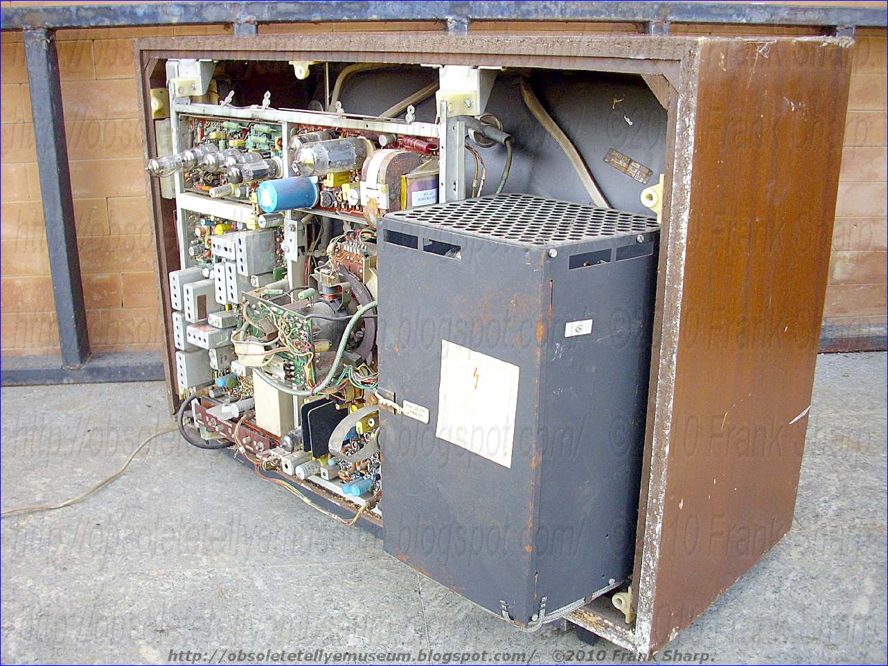


The PHILIPS CHASSIS K8 IS first PHILIPS COLOR CHASSIS developed for a 110° degree CRT Tube such as the A66-140X Delta gun type.
naturally it's tubes based but it has a hybrid technology in luminance chrominance parts and all generally around the chassis.
The Mainly Tubes based parts are power parts exception for power supply sections.
The PHILIPS CHASSIS K8 used in this set has a particular technology in Line deflection and EHT parts using 2 Line flyback transformers in a special circuit arrangement,
PHILIPS CHASSIS K8 TUBES:
- GY501
- PD510
- PL509
- PY500A
- PL509
- PY500A
- PL802
- PCL86
- PCF200
- PCF200
- PCF200
- PCF802
- PCF80
- PL508


The K8 was Philips last hybrid colour chassis. It was the first to sport a 110 degrees delta CRT. More deflection power was needed and convergence circuitry was mostly active using transistors instead of passive as before.


The K8 chassis is a further development of the K7 and K6 chassis. Tuner, IF and chroma circuits are solid state. The colour difference output unit, video output and sound are fitted with valves like in the K7 chassis. The large heat from the valves and the high power resistors burned the board of the chassis in the upper part.
It was made in 3 fundamentally different versions. The basic design was Dutch/Belgian as usual for the K series, and was designated K8, with variations K8B (for Belgian systems, 625 lines only) and K8L (tuner with separate push-buttons and a drawer instead of an integrated push-button/potmeter assembly). The K8L is never mentioned in the Model Number Survey but is marked as such on the schematic diagrams.
The picture tube with 110° deflection is much shorter than a 66 cm. picture tube with 90° deflection. As a result, the whole set has a shorter depth than the 90° colour tv sets before. Deflection circuits and convergence circuits are more complex due to the higher deflection angle.
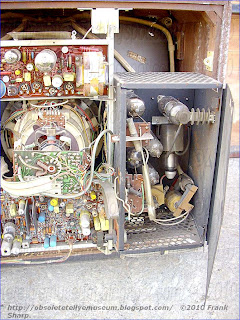
The convergence board is placed behind a door on the right side of the set (viewed in front of the set). The convergence needs active parts with high-wattage transistors here in comparison to the total passive circuits in 90° colour tv sets to generate enough signal power for the correct geometry.
The German K8D used the same rather complex EHT cage as the K8 but the signal stages and controls were more advanced compared to the K8. It already used an IC in the colour decoder while touch controls and a wired remote were also available as options.
In the K6 and K7 chassis, one line output transformer was used for deflection and EHT. This transformer was driven by a PL 509 and a PL 504. In the K8 chassis, two transformers are used, one for deflection, and another one for EHT. Both transformers are driven by a PL 519 and a PY 500A each. EHT stabilizing is realized with a GY 501 and a PD 510 as a shunt regulator like in the K7 and the K6 chassis.
The A66-140X was the first 110° deflection delta shadow mask colour picture tube. The iron-brass cover for shielding geomagnetic effects is placed now in the inside of the picture tube. Philips used colour difference concept for the colour output units. The PL 802 is for luminance output, three PCF 200 are for colour difference signal output. White balance is realized with three VDRs on the crt board. The white balance use the black level niveau as a reference for white balance control.
A particular circuit arrangement is developed in Line deflection and EHT parts, see below.

PHILIPS X26K171 (PHILIPS K8) CHASSIS K8 CIRCUIT ARRANGEMENT FOR GENERATING A SAWTOOTH CURRENT IN A LINE DEFLECTION COIL FOR A DISPLAY TUBE CONVEYING A BEAM CURRENT AND FOR GENERATING AN EHT:A circuit for generating both line deflection current and final anode voltage that has main and auxiliary generators. The main generator supplies part of the deflection current and the anode voltage, while the auxiliary generator supplies the remaining part of the deflection current. The main generator is stabilized against anode voltage variations as a result of the beam current variations and component ageing, its operating line being located just above or at the limit of saturation. The auxiliary generator is stabilized against supply voltage variations and its stabilizing circuit can also be modulated by a parabola voltage of field frequency in order to correct the East-West pincushion distortion.
 . A circuit arrangement as claimed in claim 4, wherein the filament currents of the picture display tube and the high voltage are derived from the auxiliary generator. 7. A circuit arrangement as claimed in claim 1 further comprising first and second transformers coupled to said generators respectively, each of said transformers having a tap, an auxiliary coil coupled between said taps, said taps having the same potential when the supply voltage has decreased to its lowest occurring value. 8. A circuit arrangement as claimed in claim 1 further comprising means for applying pulses of line frequency to the second stabilizing circuit which pulses are the sum of pulses which are supplied by a source coupled to one generator and a source coupled to the other generator, the pulses supplied by the source of one generator relative to the pulses supplied by the source of the other generator being in the same ratio as the portions of the sawtooth currents supplied by the two generators. 9. A circuit arrangement as claimed in claim 1 further comprising means for deriving a bias from the supply voltage and for applying it to the second stabilizing circuit, means for deriving a direct voltage from a further source coupled to the main generator, which direct voltage is dependent on the beam current variations, and means for applying said direct voltage to said bias. 10. A circuit arrangement as claimed in claim 1 further comprising a field deflection generator, and means for deriving a parabola voltage from the field generator and for applying it to the second stabilizing circuit in order to modulate the sawtooth current supplied by the auxiliary generator for the purpose of the required East-West pincushion correction, the field generator being fed with a direct voltage which is proportional to the line deflection current. 11. A circuit arrangement as claimed in claim 10 wherein said deriving means comprises an integration network to which a sawtooth voltage originating from the field generator is applied, said integration network comprising an integration capacitor that also rapidly transfers the supply voltage fluctuations to the second stabilizing circuit. 12. A circuit arrangement as claimed in claim 9, wherein the second stabilizing circuit comprises a voltage dependent resistor. 13. A circuit arrangement as claimed in claim 10 wherein the second stabilizing circuit comprises a triode and a voltage dependent resistor coupled thereto, and means for applying a parabola voltage of field frequency to the cathode of said triode. 14. A circuit arrangement as claimed in claim 10 wherein the second stabilizing circuit comprises a triode and voltage dependent resistor coupled thereto, and means for applying a parabola voltage of field frequency to the grid of said triode. 15. A circuit arrangement as claimed in claim 10 wherein the second stabilizing circuit comprises a transistor having first and second input electrodes, a resistor, a reference voltage Zener diode coupled in series with said resistor and said first electrode, the resistances of the resistor and of the Zener diode at the nominal supply voltage being in the same proportion as are the contributions of the two generators to the deflection current, means for applying a voltage of line frequency which is proportional to the line deflection current to said second input electrode of said transistor, and means for applying a parabola voltage of field frequency to said first input electrode.
The invention relates to a circuit arrangement for generating a sawtooth current in a line deflection coil for a display tube conveying a beam current and for generating an EHT, comprising means for deriving a supply voltage from the mains, at least one generator and one stabilizing circuit which stabilizes said generator substantially exclusively against EHT variations as a result of beam current variations and against variations caused by ageing of components in such a manner that the control element in the generator is active just above or at the limit of saturation. By "EHT" is means "Extra High Tension," i.e., the high anode voltage, and by "mains" is meant the A.C. power main.
 Such a circuit arrangement is known from French Pat. specification No. 1,146,166. This specification describes a circuit arrangement for generating a sawtooth current flowing through an inductor, generally the line deflection coil of a television receiver wherein the control element is a valve. This element is adjusted in such a manner that the operating line thereof in the I a - V a field is just above the limit of saturation. This has been made possible because a stabilizing circuit is provided employing a diode the cathode of which is connected through a winding of the inductor formed as a transformer to a supply voltage and whose purpose is to rectify the voltage peaks which are induced during the flyback in the said winding and which exceed the said supply voltage. The negative voltage produced on the anode of the diode then has a value which is proportional to the said voltage difference and is used as a control voltage for the first grid of the output valve of the sawtooth current. In this manner the purpose of stabilizing the operating line in the I a -V a field just above the limit of saturation (the so-called "knee") is achieved.
The circuit arrangement described above is often used as such or as some modification thereof. However, it has the following drawback. The supply voltage which serves as a reference for the amplitude of the voltage peaks to be rectified is generally derived from the mains directly so that this supply voltage proportionally varies with the inevitable fluctuations in the mains voltage. The result is that the width of the picture displayed and the EHT likewise vary as a function of the instantaneous value of the mains voltage. Therefore this is the reason why different stabilizing circuits are used wherein the picture width and the EHT are maintained constant independently of the variations in the mains voltage. Such a circuit arrangement is known, for example, from the U.S. Pat. No. 2,944,186.
 In such a circuit arrangement the operating line in the I a -V a field must be chosen far above the "knee" at the nominal mains voltage if this line is not to come below the knee when the mains voltage has decreased to its lowest possible value. In other words the anode voltage of the line output valve must be much higher than in the case of the French patent specification mentioned above. Since the current which must flow through the inductor must be fairly large, this solution involves a considerable loss of power (greater dissipation). If a transistor is used as a control element this requirement is still more stringent because such transistors are immediately destroyed when the collector voltage increases too much during the flow of the comparatively large current.
 In the case of color television wherein great powers for the deflection current and the EHT are required all this may cause an inadmissible additional dissipation also for valves. Thus, for example, a beam current of 2 mA (and even more) must be provided by the EHT source at an EHT of approximately 25 kV which is a power of approximately 50 W while corresponding numbers for monochrome television are: 0.5 mA, 18 kV that is to say 9 W. Therefore it is evident that it is not possible to meet all requirements simultaneously, to wit the supply of the deflection and EHT energy and the stabilization against variations in the EHT, ageing of the components and variations in the supply voltage derived from the mains.
An object of the present invention is to solve the problem described hereinbefore and to this end it is characterized in that the said generator is formed as a main generator which provides a portion of the sawtooth current to be generated and the EHT and that furthermore an auxiliary generator is provided which supplies the remaining portion of the sawtooth current, and a second stabilizing circuit which stabilizes the auxiliary generator against variations in the supply voltage, the two generators being mutually decoupled, all this for the purpose of maintaining the width of the picture displayed on the screen of the display tube constant under all circumstances. It is to be noted that since the main generator is stabilized just above or at the limit of saturation its own dissipation is always at a minimum.
Furthermore it is to be noted that the circuit arrangement according to the invention does not envisage a complete stabilization of the EHT and of the amplitude of the current flowing through the deflection coils. In fact, the internal impedance of the EHT source, although being reduced by the first stabilizing circuit, is not zero which as a matter of fact is not desirable due to evident reasons of safety. In addition as already stated the invention is based on the recognition of the fact that neither the part of the deflection current provided by the main generator nor the EHT are stabilized against variations in the supply voltage. Nevertheless it is possible to stabilize the width of the picture displayed. As is known this width can be maintained constant if the EHT varies at the same percentage as does the supply voltage and if the deflection current varies at half the percentage. If, for example, the mains voltage and hence also the supply voltage increase by 10 percent, the EHT must increase by 10 percent and the deflection current must increase by 5 percent.
 This object can be achieved in a very simple manner by means of a special embodiment of a circuit arrangement according to the invention and to this end the circuit arrangement is characterized in that the two generators are adjusted in such a manner that the part of the sawtooth current provided by the main generator is equal to the part which is provided by the auxiliary generator.
Furthermore the invention is based on the recognition of the fact that the second stabilizing circuit (that of the auxiliary generator) is used for performing the so-called East-West raster correction of the pincushion distortion. If the lengths of the lines displayed on the screen are to remain constant during the sweep of one field period, the amplitude of the sawtooth line deflection current must vary in accordance with a parabola function during this sweep and this in such a manner that a maximum value is reached substantially in the middle of the sweep. This East-West correction is obtained by modulating the sawtooth line deflection current by a parabola function of field frequency. This may in principle be achieved in a simple manner by applying a parabola voltage of field frequency to the grid of the line output valve to which the control pulse of the line frequency is applied. However, it will be readily evident that the desired object cannot quite be achieved in that case since the introduced amplitude variation is counteracted by the first stabilizing circuit which in fact attempts to maintain the amplitude of the line deflection current constant. A special embodiment of the circuit arrangement according to the invention is characterized in that a parabola voltage derived from the field generator is applied to the second stabilizing circuit in order to modulate the sawtooth current provided by the auxiliary generator for the purpose of the required East-West pincushion correction, the field generator being fed with a direct voltage which is proportional to the line deflection current.
 In this connection a further particular advantage of the circuit arrangement according to the invention becomes manifest. If the main generator had been chosen for this modulation, the EHT would also have varied due to the modulation. On the one hand this would somewhat detrimentally influence the East-West correction to be performed and on the other hand it would cause a variation in brightness during one field period. These drawbacks are obviated by modulating the auxiliary generator only.
In order that the invention may be readily carried into effect a few embodiments thereof will not be described in detail by way of example with reference to the accompanying diagrammatic drawings in which:
FIG. 1 shows the general principle of coupling the main generator and the auxiliary generator to the line deflection coils.
FIG. 2 shows an embodiment of a line deflection circuit employing valves wherein the line deflection coils are connected in parallel.
FIG. 3 and FIG. 4 show the operating line in the I a -V a and the I c -V c fields of the main generator and the auxiliary generator, respectively.
FIGS. 5, 6, 7 and 8 show a few other embodiments of the second stabilizing circuit of FIG. 2.
FIGS. 9 and 10 show a circuit arrangement according to the invention wherein the line deflection coils are arranged in series.
FIG. 11 shows a circuit arrangement wherein the control elements are transistors.
In FIG. 1 the reference numerals 1 and 2 denote the main and auxiliary generators, respectively, whi ch are coupled through transformers 3 and 4 to the line deflection coil 5. Main generator 1 is directly coupled by means of winding 6 to transformer 3 while line deflection coil 5 is coupled to the same transformer by means of winding 7 (n 7 turns). Furthermore a winding 8 (n 8 turns) is wound on transformer 3 and a winding 9 (n 9 turns) is wound on transformer 4 which windings are connected together through an auxiliary coil 10 which coil 10 is exclusively provided to decouple generators 1 and 2. Windings 11 and 12 (n 12 turns) on transformer 4 correspond to windings 6 and 7 on transformer 3. Both generators contribute to the sawtooth deflection current i Y which flows through line deflection coil 5 while a compensation current i k flows through auxiliary coil 10.
It must not be possible for auxiliary generator 2 to exert influence on main generator 1, that is to say, the deflection current originating from auxiliary generator 2 must not induce a flux in transformer 3, in other words the voltages V 7 and V 8 which are produced by generator 2 at the terminals of windings 7 and 8 must be zero. This may be calculated when generator 1 is switched off and in that case the following relations apply:
i Y /i k = n 8 / n 7 and V 12 /V 9 = n 12 /n 9 = (i Y ωL 5 )/(i k ωL 10 )
wherein L 5 and L 10 are the inductances of coils 5 and 10, respectively. The ratio of the inductances L 5 and L 10 can be calculated therefrom:
Conversely it must not be possible for generator 1 to exert influence on generator 2, in other words when generator 2 is disconnected the voltages V 12 and V 9 must be zero. In that case the following relations apply:
i k / i Y = n 12 /n 9 and V 7 /V 8 = n 7 /n 8 = (i Y ω L 5 )/(i k ωL 10 )
from which follows
This is the same condition as the one above, in other words, if these conditions are satisfied the two generators are mutually completely decoupled. As is evident from FIG. 1 this is achieved by coupling windings 8 and 9, as it were, oppositely to windings 7 and 12.
In practice, the principal circuit diagram described may be formed in different manners. A first embodiment is sho wn in FIG. 2 where corresponding elements have the same reference numerals as those in FIG. 1. In this figure the reference numerals 1 and 2 denote line deflection generators which may be formed in known manner and which are provided with a shunt or series booster circuit; in this embodiment they are both provided with a series booster circuit. Main generator 1 is controlled by a control signal 13 and is formed as a flyback driven high voltage generator for generating the EHT V H , EHT winding 14 being wound on transformer 3. The purpose of this transformer is to step up the high peaks occurring during the flyback so as to obtain the EHT V H after rectification. The transformer 3 is tuned in known manner by means of circuit 16 to two parallel resonance one of which has the flyback frequency and the other is substantially an odd harmonic of the first, capacitor 15 representing an interconnection with respect to alternating current between the primary and the secondary. Auxiliary generator 2 is controlled by the same control signal 13 as is main generator 1 or without any objection by a source other than 1 provided that an equivalent control signal of line frequency is applied to its control grid. Coil 10 represents the auxiliary coil while the two half line deflection coils 5 are arranged in parallel in this embodiment. Transformer 17 serves to modulate the line deflection current through the two half coils 5 (the so-called difference current control) in order to eliminate the effect of the anisotropic astigmatism in the corners of the picture display tube as described in the U.S. Pat. application Ser. No. 832,957, filed on June 13, 1969. Since transformer 17 is bifilarly wound and forms a bridge circuit with the half deflection coils which circuit is in balance it does not represent an impedance for the deflection current i Y . The adjustable and damped inductor 18 through which current i Y flows serves for the usual linearity correction. The points in FIG. 2 at windings 12 and 9 on transformer 4 show that the flux generated by current i Y in winding 12 is opposite to the flux which is generated by current i k in winding 9. This corresponds to the manner of decoupling as described with reference to FIG. 1. Since transformer 4 is not used to produce an EHT, a non-tuned transformer would be sufficient. It is, however, found to be advantageous to tune it anyway in the above-described known manner because also transformer 4 has leakage inductance. Without the said tuning ringing might occur, but in addition the flyback periods of the two generators might become unequal.
Capacitor 19 for the S correction must be arranged in series with winding 7 on transformer 3 of main generator 1. In fact, the current which flows through winding 8 is not the deflection current i Y , but i Y + i k - i p , wherein i k is the compensation current flowing through auxiliary coil 10 and i p is the primary current of transformer 3. Since the cathode current of pentode 20 in generator 1 is not proportional to the deflection current i Y , this current cannot be used for centration which must be performed by means of circuit 21 in order that the shift remains exactly correlated with the deflection current. The current taken up by circuit 21 has a value which relative to that of deflection current i Y is so low that the current flowing through capacitor 19 and resistor 22 is substantially equal to i Y . Furthermore a resistor 22 of small value is incorporated in series with capacitor 19. Because the current flowing through capacitor 19 has a sawtooth form the voltage across resistor 22 is the combination of a sawtooth voltage and a parabola voltage. If resistor 22 is formed as a potentiometer the voltage between the wiper on potentiometer 22 and the junction 19-22 can be used for adjustment of the dynamic convergence if the circuit arrangement according to FIG. 2 is used in a color television receiver.
Main generator 1 is provided with a stabilizing circuit which stabilizes this generator in known manner against variations in the EHT as a result of beam current variations as a function of the brightness (= the load on winding 14) and against variations caused by ageing of components. In FIG. 2 the voltage dependent resistor (VDR) 23 is included by way of example which resistor rectifies line flyback pulses producing a negative voltage which serves as a control voltage for the control grid of pentode 20 in generator 1. The lower end of VDR 23 is connected to the wiper on a potentiometer 24' one end of which is connected to earth and the other end of which is connected through a resistor of large value to the series booster capacitor. If the wiper on potentiometer 24' is provided at the lower end, main generator 1 is not stabilized against variations in the mains voltage; in case of a different position of this wiper the extent of stabilization against mains voltage variations is optionally adjustable.
Since the pulses included in winding 6 of transformer 3 during the line flyback are substantially proportional to the instantaneous value of the supply voltage, it is advantageous to rectify the pulses produced on a tapping of winding 6 by means of rectifier 25 in order to generate a voltage for a second grid of the display tube. In fact, the voltages on the cathodes and the Wehnelt cylinders of this display tube vary proportionally to the supply voltage. Furthermore the main generator 1 is adjusted by means of potentiometers 24' and 24" in such manner that its operating line in the I a - V a field of pentode 20 may be represented by line PQ in FIG. 3. As already described in the preamble the line PQ is placed as closely as possible to the limit of saturation which is represented by the line section NO in order to maintain the natural dissipation of t his pentode as small as possible.
Auxiliary generator 2 is provided with a second stabilizing circuit which stabilizes this generator in known manner against supply voltage variations. In FIG. 2 the combination of a triode 26 and a further voltage dependent resistor (VDR) 27 which is included in the cathode line of the triode serves for this purpose. As is known a negative voltage which serves as a control voltage for the control grid of pentode 28 in generator 2 is produced on the anode of the triode. The adjustment of this pentode is chosen to be such (see FIG. 4) that the operating line thereof in the I a -V a field is placed sufficiently far above the "knee" so that the envisaged stabilization against supply voltage variations can be carried into effect. It is a recognition of the invention to choose the operating line at the nominal supply voltage such that the largest occurring variation in the supply voltage in negative direction causes the operating line to be displaced just above the "knee. " In fact, in such a case the same contribution to deflection current i Y is still provided by auxiliary generator 2 while the dissipation is maintained at a minimum. The foregoing may be explained with reference to the following figures. If, for example, pentode 20 is a PL 509 and if the control voltage 13 thereof has a sawtooth form, the anode current of this pentode may increase during the scan period from zero to approximately 800 mA at the nominal supply voltage which represents a mean value of approximately 360 mA throughout the line period while the mean anode voltage is approximately 50 V. The natural dissipation is 360 × 50 × 10 -3 = 18 W at an average. If the supply voltage variations had been taken into account, an anode voltage of, for example, 70 V should have been chosen at the nominal mains voltage which is an additional increase of 360 × 20 × 10 -3 = 7.2 W. For a maximum mains voltage of 240 V an additional power of 7.2 W must be supplied.
 On account of the same reason the number of turns on windings 8 and 9 must be chosen to be such that there does not flow any compensation current i k through balancing auxiliary coil 10 when the supply voltage has decreased to its lowest occurring value: since the two generators supply exclusively deflection energy the circuit arrangement then has its maximum efficiency and since the two valves are then adjusted just above their "knees" the overall dissipation is at a minimum under these circumstances. If necessary auxiliary coil 10 may be arranged between tappings on windings 8 and 9.
As already described in the preamble the second stabilizing circuit is modulated by a parabola voltage of field frequency so as to correct the East-West pincushion distortion. This may be achieved in accordance with the embodiment of FIG. 2 by integrating a sawtooth voltage 29 originating from the field generator by means of an RC network 30-31 and to apply the resultant parabola voltage 32 to the grid of triode 26. It is alternatively possible (see FIG. 5) to arrange this parabola voltage of field frequency 32 in series with VDR 27, but then at a polarity which is reversed relative to that of the previous case. It is true that the advantage of the higher input impedance of the grid is then lost so that the parabola voltage must have slightly greater amplitude, but is should be taken into account that a sawtooth voltage of field frequency is not always available at the desired polarity in the television receiver in which the circuit arrangement is used.

In the embodiment of FIG. 2 in which the second stabilizing circuit receives the voltage of field frequency at the grid of triode 26, integration capacitor 31 of the RC integration network is arranged between said grid and the supply voltage. In this simple manner capacitor 31 also serves to transfer the fluctuations in the supply voltage quickly to the second stabilizing circuit. The same applies to the embodiment of FIG. 5.
In FIG. 2 the second stabilizing circuit is formed as the combination of a triode and a VDR. It is evident that any other known stabilizing circuit for the line deflection is likewise suitable for this purpose. Thus said stabilizing circuit may be formed as a VDR 33 to which the parabola voltage is also applied provided that this voltage is high enough because the amplification of the triode is no longer available (see FIG. 6).
Since the second stabilizing circuit is modulated by the parabola voltage in one of the manners described, the following problem presents itself. The current provided by auxiliary generator 2 is rendered independent of variations in the supply voltage or, in other words, the contribution of auxiliary generator 2 to the overall deflection current is dependent on the value of this supply voltage, for if α i Y and β i Y are the contributions of the first and second generators to the deflection current, then α varies with the supply voltage while β remains constant from which is apparent that the ratio β : α is a function of the supply voltage. If the amplitude of the modulating parabola voltage 32 is constant this results in over- or undermodulation in case of variations in the supply voltage. If, for example, the two generators each supply half the deflection current i Y at the nominal supply voltage and if the amplitude of the modulating current is 20 percent of i Y , the two generators provide 0.5 i Y and (0.5 + 0.2)i Y , respectively. If the supply voltage decreases by 10 percent the main generator, which is not stabilized against this variation, provides 0.45 i Y while the auxiliary generator continues to provide (0.5 + 0.2) i Y which means that the modulating current has become 20 : 95 = 21 percent of the new deflection current. Consequently, an overcompensation occurs.
The problem can be solved in an elegant manner when the applied parabola voltage does not remain constant, but when it varies by the same factor as does the line deflection current, that is to say, as already previously described, by a factor which is 50 percent of the factor by which the supply voltage varies. In the above-mentioned example of calculation the modulating current then decreases by a factor of 5 percent and and hence the auxiliary generator provides (0.5 + 0.19) i Y . The amplitude of the modulating current is 19 : 95 = 20 percent of the deflection current so it has proportionally remained constant. The same reasoning applies when the supply voltage would increase. The step described may be carried into effect by feeding the field generator with a direct voltage which is proportional to the line deflection current, which direct voltage can be generated by rectifying, with the aid of diode 34 of FIG. 2, the parabola voltage which is produced across capacitor 19 for the S correction. The direct voltage derived from point 35 may be applied to the field generator, for the current flowing through capacitor 19 is nothing but deflection current i Y since the current flowing through circuit arrangement 21 is negligibly small relative thereto. It is alternatively possible to provide an additional winding on the two transformers 3 and 4 in such a manner that the voltages induced therein are in the same properties as are the contributions of the two generators to deflection current i Y . These voltages may be added together and the resultant voltage may be rectified by means of diode 34.
A winding 36 across which line flyback pulses are produced is provided on transformer 3 of main generator 1 which pulses are applied through potentiometer 37 to the second stabilizing circuit while also flyback pulses from winding 38 on transformer 4 of auxiliary generator 2 are applied to the same stabilizing circuit. In fact, this stabilizing circuit must receive information regarding the instantaneous value of the deflection current. Potentiometer 37 then serves to give the pulses applied to the second stabilizing circuit a ratio which is equal to the ratio of the contributions of the two generators to the deflection current. However, since the amplitude of the pulses generated across winding 36 is also dependent on the variations in the EHT V H as a result of its internal impedance, which is not negligible, the part of the deflection current provided by auxiliary generator 2 would also vary which would cause a variation in the picture width. Therefore the second stabilizing circuit must also receive information regarding these EHT variations. In the embodiment of FIG. 2 this purpose is achieved by connecting the lower end of potentiometer 39 not to earth but to an RC parallel network 40 which is provided at the lower end of winding 14. In fact, an adjustable direct voltage which is directly proportional to the beam current is produced across this network 40. In this manner the deflection current provided by auxiliary generator 2 slightly decreases as the beam current increases. As a matter of fact the direct voltage produced across network 40 may be used elsewhere in the display device so as to prevent the beam current from exceeding a given value.
As described hereinbefore according to the recognition of the invention the deflection current must vary by a percentage which is equal to half that of the variation in the supply voltage. The second stabilizing circuit thus must have a stabilization factor relative to the supply voltage which is equal to 2. This is adjusted by means of potentiometer 39.
However, the previously described stabilizing circuit for the auxiliary generator 2 has the drawback that it provides two adjusting possibilities, to wit potentiometers 37 and 39. Associated with each position of one potentiometer is a position of the other by which the series booster voltage of the auxil iary generator can be adjusted, but there is only one position at which the width of the picture does not vary with the supply voltage. This is not very practical. This drawback can be obviated with the aid of the circuit arrangement shown in FIG. 7. In this circuit arrangement the second stabilizing circuit is formed as a transistor 41 whose base line includes a resistor 42 in series with an element 43 supplying a reference voltage, for example a Zener diode, in such a manner that the voltages across resistor 42 and Zener diode 43 have the same proportion in case of nominal supply voltage as do the contributions of the two generators to the deflection current. Then the variation of the base voltage is half the variation in the supply voltage. The emitter of transistor 41 is controlled by a voltage of line frequency which is proportional to the deflection current i Y which voltage can be obtained by arranging, for example, a resistor 44 of small value in series with the parallel arrangement of the two deflection coil halves 5 or by providing a few windings on the yoke of the deflection unit or by means of an auxiliary transformer on the line deflection coils while the parabola voltage 32 is applied to the base. The same purpose as the one described above is now achieved with the aid of only one adjustment, to wit the adjustment of transistor 41. It is alternatively possible without any objection to incorporate resistor 42 and Zener diode 43 in the emitter line of transistor 41 and the information proportional to the line deflection current in the base line.
A drawback of the previously described stabilizing circuit is that that the voltage which is present at the control grid of pentode 28 must remain negative throughout the line period, that is to say, a mean grid voltage of approximately -30 to -60 V dependent on the waveform, the amplitude of the control voltage and on the negative voltage which is required at the end of the scan. Since this grid voltage serves as a collector voltage for transistor 41 this mean value is fairly high, at least so for many transistors. FIG. 8 shows an embodiment which is more suitable in this respect. In this embodiment the collector voltage of transistor 41 is laid down at a fixed level, for example, -20 V and control signal 13 is clamped against this level by means of a diode. This embodiment provides the advantage that the action of stabilization has become more effective because variations in the amplitude of control signal 13 as a result of variations in the supply voltage are rectified by the clamping diode which is a contribution to the negative voltage for the control grid. This contribution need not then be provided by the control circuit. A diode is provided in the base circuit of transistor 41 in order to rectify the peaks of the voltage present on the wiper of potentiometer 39 so that the admissible reverse voltage for the base-emitter diode of transistor 41 is not exceeded. Furthermore, the emitter voltage changes to a small extent because the current derived from the supply voltage and flowing through Zener diode 43 and resistor 42 also flows through the resistor in network 40: this has no influence when the base of transistor 41 undergoes a proportional variation which may be effected by choosing the correct value for the resistor between potentiometer 39 and the supply voltage.
So far nothing has been stated about the ration of the contributions of the deflection currents provided by the two generators and all ratios are in principle possible. It will, however, be readily evident that the contribution of auxiliary generator 2 must at any rate not decrease to zero, for generator 2 in FIG. 1 may be considered a voltage source parallel to a circuit (= winding 11 and the parasitic capacitances). If generator 2 provides a current the two generators do not "see" each other as has been proved, but if this current is zero, that is to say, if the line between voltage source 2 and the circuit is interrupted, windings 12 and 9 are only coupled together and the transformed inductor 10 is inseries with deflection coil 5. This may cause heavy free oscillations which become visible as a velocity modulation of the dot of light on the screen of the display tube. The contribution provided by generator 2 may therefore not become smaller than approximately 2 percent of the overall supplied current. In addition it would make little sense to have auxiliary generator 2 supply more current than main generator 1 since the dissipation in the auxiliary generator would become greater without discharging the main generator considerably thereby, since this generator must provide the (great) EHT power anyway.
It will now be proved that a ratio of 1 : 1 that is the same contribution of the two generators (at nominal supply voltage) is preferred to some extent. If i Y and i Y are the contributions of the two generators at an arbitrary supply voltage, while i Y and i Y represent the same values at nominal supply voltage, the following relations apply when this supply voltage has varied by a factor of 1 + s and when the main generator 1 is not stabilized at all against mains voltage variations, that is to say, when the wiper on potentiometer 24' is connected to earth:
wherein n is the stabilization factor of auxiliary generator 2 against mains voltage variations. In order that the width of the picture remains constant there must apply that:
that is to say, the overall deflection current varies by the percentage s/2 . From this follows: ##SPC1##
Since the position of the wiper on potentiometer 24' may vary, the first stabilizing circuit may have a mains voltage stabilization factor of m which, likewise as n, is smaller that 1; the last formula then becomes:
It can be seen that n = 0 when i Y = i Y for any value of m, or in words: at the ratio of 1 : 1 of the deflection currents supplied at nominal mains voltage the auxiliary generator is completely stabilized against mains voltage variations independently of the stabilization factor m of the main generator, in other words the two stabilizing circuits can now be fully independent of each other.
The ratio 1 : 1 permits of writing that the deflection current must be
when the supply voltage is multiplied by a factor of 1 + s. The term
is then the current provided by main generator 1 which entirely follows the supply voltage fluctuations. The second term i Y /2 represents the current provided by auxiliary generator 2 which current remains constant. The advantage of this ratio of 1 : 1 is then evident. A variation in the mains voltage does not cause any variation in the picture width, but only a variation in the EHT (for this varies with the supply voltage variations) while auxiliary generator 2 does not exert any influence on the EHT. Thus the two functions of the line output generator are separated from each other, that is to say, they have been made independent of each other. Such an independency was not possible with the circuit arrangements known so far.
 It is allowed to optionally stabilize or not stabilize main generator 1 against supply voltage variations while the second stabilizing circuit does stabilize auxiliary generator 2 completely. This second stabilizing circuit then need no longer receive information regarding the value of the overall deflection current. Winding 36 in FIG. 2 can then be omitted while resistor 44 in FIGS. 7 and 8 may be replaced by, for example, a winding on transformer 4. In addition resistor 42 is now omitted.
It is true that it must be possible for pentode 28 in auxiliary generator 2 to supply a comparatively large power at the ratio of 1 : 1. However, the advantage of an independent EHT generation and picture width stabilization is so important that a pentode for generator 2 suitable for a greater dissipation may be accepted. Since generator 2 need not supply any EHT power, its pentode may nevertheless be a valve which is suitable for a smaller dissipation than is pentode 20 in main generator 1. This means that the cathode of pentode 28 may be smaller and the insulation between this cathode and the filament for heating thereof may be thinner resulting in the heating period of auxiliary generator 2 being shorter upon switching on than that of main generator 1. It is then advantageous to provide additional windings on transformer 4 so as to provide the picture tube, the EHT rectifier and optionally the series booster diode of main generator 1 with filament power. Not only are the relevant filament voltages constant independently of the mains voltage variations but due to the shorter heating period of auxiliary generator 2 the picture tube has already completely heated up at the instant when main generator 1 starts to operate. If one generator were present and if the filament voltage for the picture tube were derived from its output transformer, the heating period of the picture tube cathode would not commence until this single generator would start to operate after it was switched on. Consequently, this is a longer period than when this filament supply would be effected by auxiliary generator 2.
FIG. 2 described so far related to a line deflection circuit in which the two halves of deflection coils 5 are arranged in parallel. The foregoing will of course also apply when the said halves are arranged in series. In this respect reference is made to FIG. 9 in which only the important elements of FIG. 2 are shown and denoted by the same reference numerals. Since the two halves 5' and 5" of the deflection coil are arranged in series the entire circuit arrangement must be symmetric which is apparent from FIG. 9. For this reason coil 18 for the linearity control must have a bifilar winding and capacitor 19 for the S correction must be split up into two equal parts 19', 19". Since capacitors 19' and 19" should exactly be equal for a satisfactory symmetry, only one capacitor is used and an electric center is made by means of a bifilarly wound coil 45', 45" (see FIG. 10). This coil may alternatively be formed as a transformer wherein the secondary serves for generating (21) the centering current which is smoothed by capacitors 46' and 46".
FIG. 11 shows by way of example a circuit arrangement according to the invention wherein transistors are employed as control elements and in which the ratio between the sawtooth currents is 1 : 1 and wherein the deflection coils are arranged in series. The corresponding components of the previous Figures have the same reference numerals. The paramount difference from a circuit arrangement employing valves resides in the fact that it is not possible to control a transistor, which actually functions as a switch, in the same way as a valve. It is possible to use a so-called "knee stabilization" in contrast to what is effected with valves for the reasons explained in the French Pat. specification No. 1,146,166. If it is ensured that the control currents of transistors 20' and 28' of FIG. 11 are sufficiently large, the operating line of the two transistors in the I c -V c field will substantially always extend under any circumstances in accordance with the line ON in FIG. 3 (wherein I c and V c should be read instead of I a and V a , respectively). If in addition the operating point would be above the "knee," the dissipation, as already stated, might become inadmissibly high.
In FIG. 11 main generator 1 is not stabilized against variations in the supply voltage V B whereas auxiliary generator 2 is stabilized, namely by means of transistor 26'. Transistor 26' receives a parabola voltage 32 of field frequency from a circuit arrangement 17 (not further described) for the purpose of correcting the East-West pincushion distortion as well as a direct voltage which has a variation such that the variation in the collector voltage of transistor 26' is always equal to that of supply voltage V B . The voltage across auxiliary generator 2 then remains constant which means that the part i Y of the sawtooth current supplied by auxiliary generator 2 is constant.
The circuit arrangement described above is often used as such or as some modification thereof. However, it has the following drawback. The supply voltage which serves as a reference for the amplitude of the voltage peaks to be rectified is generally derived from the mains directly so that this supply voltage proportionally varies with the inevitable fluctuations in the mains voltage. The result is that the width of the picture displayed and the EHT likewise vary as a function of the instantaneous value of the mains voltage. Therefore this is the reason why different stabilizing circuits are used wherein the picture width and the EHT are maintained constant independently of the variations in the mains voltage. Such a circuit arrangement is known, for example, from the U.S. Pat. No. 2,944,186.
An object of the present invention is to solve the problem described hereinbefore and to this end it is characterized in that the said generator is formed as a main generator which provides a portion of the sawtooth current to be generated and the EHT and that furthermore an auxiliary generator is provided which supplies the remaining portion of the sawtooth current, and a second stabilizing circuit which stabilizes the auxiliary generator against variations in the supply voltage, the two generators being mutually decoupled, all this for the purpose of maintaining the width of the picture displayed on the screen of the display tube constant under all circumstances. It is to be noted that since the main generator is stabilized just above or at the limit of saturation its own dissipation is always at a minimum.
Furthermore the invention is based on the recognition of the fact that the second stabilizing circuit (that of the auxiliary generator) is used for performing the so-called East-West raster correction of the pincushion distortion. If the lengths of the lines displayed on the screen are to remain constant during the sweep of one field period, the amplitude of the sawtooth line deflection current must vary in accordance with a parabola function during this sweep and this in such a manner that a maximum value is reached substantially in the middle of the sweep. This East-West correction is obtained by modulating the sawtooth line deflection current by a parabola function of field frequency. This may in principle be achieved in a simple manner by applying a parabola voltage of field frequency to the grid of the line output valve to which the control pulse of the line frequency is applied. However, it will be readily evident that the desired object cannot quite be achieved in that case since the introduced amplitude variation is counteracted by the first stabilizing circuit which in fact attempts to maintain the amplitude of the line deflection current constant. A special embodiment of the circuit arrangement according to the invention is characterized in that a parabola voltage derived from the field generator is applied to the second stabilizing circuit in order to modulate the sawtooth current provided by the auxiliary generator for the purpose of the required East-West pincushion correction, the field generator being fed with a direct voltage which is proportional to the line deflection current.
In order that the invention may be readily carried into effect a few embodiments thereof will not be described in detail by way of example with reference to the accompanying diagrammatic drawings in which:
FIG. 1 shows the general principle of coupling the main generator and the auxiliary generator to the line deflection coils.
FIG. 2 shows an embodiment of a line deflection circuit employing valves wherein the line deflection coils are connected in parallel.
FIG. 3 and FIG. 4 show the operating line in the I a -V a and the I c -V c fields of the main generator and the auxiliary generator, respectively.
FIGS. 5, 6, 7 and 8 show a few other embodiments of the second stabilizing circuit of FIG. 2.
FIGS. 9 and 10 show a circuit arrangement according to the invention wherein the line deflection coils are arranged in series.
FIG. 11 shows a circuit arrangement wherein the control elements are transistors.
In FIG. 1 the reference numerals 1 and 2 denote the main and auxiliary generators, respectively, whi
 ch are coupled through transformers 3 and 4 to the line deflection coil 5. Main generator 1 is directly coupled by means of winding 6 to transformer 3 while line deflection coil 5 is coupled to the same transformer by means of winding 7 (n 7 turns). Furthermore a winding 8 (n 8 turns) is wound on transformer 3 and a winding 9 (n 9 turns) is wound on transformer 4 which windings are connected together through an auxiliary coil 10 which coil 10 is exclusively provided to decouple generators 1 and 2. Windings 11 and 12 (n 12 turns) on transformer 4 correspond to windings 6 and 7 on transformer 3. Both generators contribute to the sawtooth deflection current i Y which flows through line deflection coil 5 while a compensation current i k flows through auxiliary coil 10.
It must not be possible for auxiliary generator 2 to exert influence on main generator 1, that is to say, the deflection current originating from auxiliary generator 2 must not induce a flux in transformer 3, in other words the voltages V 7 and V 8 which are produced by generator 2 at the terminals of windings 7 and 8 must be zero. This may be calculated when generator 1 is switched off and in that case the following relations apply:
i Y /i k = n 8 / n 7 and V 12 /V 9 = n 12 /n 9 = (i Y ωL 5 )/(i k ωL 10 )
wherein L 5 and L 10 are the inductances of coils 5 and 10, respectively. The ratio of the inductances L 5 and L 10 can be calculated therefrom:
Conversely it must not be possible for generator 1 to exert influence on generator 2, in other words when generator 2 is disconnected the voltages V 12 and V 9 must be zero. In that case the following relations apply:
i k / i Y = n 12 /n 9 and V 7 /V 8 = n 7 /n 8 = (i Y ω L 5 )/(i k ωL 10 )
from which follows
This is the same condition as the one above, in other words, if these conditions are satisfied the two generators are mutually completely decoupled. As is evident from FIG. 1 this is achieved by coupling windings 8 and 9, as it were, oppositely to windings 7 and 12.
In practice, the principal circuit diagram described may be formed in different manners. A first embodiment is sho
wn in FIG. 2 where corresponding elements have the same reference numerals as those in FIG. 1. In this figure the reference numerals 1 and 2 denote line deflection generators which may be formed in known manner and which are provided with a shunt or series booster circuit; in this embodiment they are both provided with a series booster circuit. Main generator 1 is controlled by a control signal 13 and is formed as a flyback driven high voltage generator for generating the EHT V H , EHT winding 14 being wound on transformer 3. The purpose of this transformer is to step up the high peaks occurring during the flyback so as to obtain the EHT V H after rectification. The transformer 3 is tuned in known manner by means of circuit 16 to two parallel resonance one of which has the flyback frequency and the other is substantially an odd harmonic of the first, capacitor 15 representing an interconnection with respect to alternating current between the primary and the secondary. Auxiliary generator 2 is controlled by the same control signal 13 as is main generator 1 or without any objection by a source other than 1 provided that an equivalent control signal of line frequency is applied to its control grid. Coil 10 represents the auxiliary coil while the two half line deflection coils 5 are arranged in parallel in this embodiment. Transformer 17 serves to modulate the line deflection current through the two half coils 5 (the so-called difference current control) in order to eliminate the effect of the anisotropic astigmatism in the corners of the picture display tube as described in the U.S. Pat. application Ser. No. 832,957, filed on June 13, 1969. Since transformer 17 is bifilarly wound and forms a bridge circuit with the half deflection coils which circuit is in balance it does not represent an impedance for the deflection current i Y . The adjustable and damped inductor 18 through which current i Y flows serves for the usual linearity correction. The points in FIG. 2 at windings 12 and 9 on transformer 4 show that the flux generated by current i Y in winding 12 is opposite to the flux which is generated by current i k in winding 9. This corresponds to the manner of decoupling as described with reference to FIG. 1. Since transformer 4 is not used to produce an EHT, a non-tuned transformer would be sufficient. It is, however, found to be advantageous to tune it anyway in the above-described known manner because also transformer 4 has leakage inductance. Without the said tuning ringing might occur, but in addition the flyback periods of the two generators might become unequal.rding to FIG. 2 is used in a color television receiver.Main generator 1 is provided with a stabilizing circuit which stabilizes this generator in known manner against variations in the EHT as a result of beam current variations as a function of the brightness (= the load on winding 14) and against variations caused by ageing of components. In FIG. 2 the voltage dependent resistor (VDR) 23 is included by way of example which resistor rectifies line flyback pulses producing a negative voltage which serves as a control voltage for the control grid of pentode 20 in generator 1. The lower end of VDR 23 is connected to the wiper on a potentiometer 24' one end of which is connected to earth and the other end of which is connected through a resistor of large value to the series booster capacitor. If the wiper on potentiometer 24' is provided at the lower end, main generator 1 is not stabilized against variations in the mains voltage; in case of a different position of this wiper the extent of stabilization against mains voltage variations is optionally adjustable.
his pentode as small as possible.Auxiliary generator 2 is provided with a second stabilizing circuit which stabilizes this generator in known manner against supply voltage variations. In FIG. 2 the combination of a triode 26 and a further voltage dependent resistor (VDR) 27 which is included in the cathode line of the triode serves for this purpose. As is known a negative voltage which serves as a control voltage for the control grid of pentode 28 in generator 2 is produced on the anode of the triode. The adjustment of this pentode is chosen to be such (see FIG. 4) that the operating line thereof in the I a -V a field is placed sufficiently far above the "knee" so that the envisaged stabilization against supply voltage variations can be carried into effect. It is a recognition of the invention to choose the operating line at the nominal supply voltage such that the largest occurring variation in the supply voltage in negative direction causes the operating line to be displaced just above the "knee. " In fact, in such a case the same contribution to deflection current i Y is still provided by auxiliary generator 2 while the dissipation is maintained at a minimum. The foregoing may be explained with reference to the following figures. If, for example, pentode 20 is a PL 509 and if the control voltage 13 thereof has a sawtooth form, the anode current of this pentode may increase during the scan period from zero to approximately 800 mA at the nominal supply voltage which represents a mean value of approximately 360 mA throughout the line period while the mean anode voltage is approximately 50 V. The natural dissipation is 360 × 50 × 10 -3 = 18 W at an average. If the supply voltage variations had been taken into account, an anode voltage of, for example, 70 V should have been chosen at the nominal mains voltage which is an additional increase of 360 × 20 × 10 -3 = 7.2 W. For a maximum mains voltage of 240 V an additional power of 7.2 W must be supplied.
As already described in the preamble the second stabilizing circuit is modulated by a parabola voltage of field frequency so as to correct the East-West pincushion distortion. This may be achieved in accordance with the embodiment of FIG. 2 by integrating a sawtooth voltage 29 originating from the field generator by means of an RC network 30-31 and to apply the resultant parabola voltage 32 to the grid of triode 26. It is alternatively possible (see FIG. 5) to arrange this parabola voltage of field frequency 32 in series with VDR 27, but then at a polarity which is reversed relative to that of the previous case. It is true that the advantage of the higher input impedance of the grid is then lost so that the parabola voltage must have slightly greater amplitude, but is should be taken into account that a sawtooth voltage of field frequency is not always available at the desired polarity in the television receiver in which the circuit arrangement is used.

In the embodiment of FIG. 2 in which the second stabilizing circuit receives the voltage of field frequency at the grid of triode 26, integration capacitor 31 of the RC integration network is arranged between said grid and the supply voltage. In this simple manner capacitor 31 also serves to transfer the fluctuations in the supply voltage quickly to the second stabilizing circuit. The same applies to the embodiment of FIG. 5.
In FIG. 2 the second stabilizing circuit is formed as the combination of a triode and a VDR. It is evident that any other known stabilizing circuit for the line deflection is likewise suitable for this purpose. Thus said stabilizing circuit may be formed as a VDR 33 to which the parabola voltage is also applied provided that this voltage is high enough because the amplification of the triode is no longer available (see FIG. 6).
Since the second stabilizing circuit is modulated by the parabola voltage in one of the manners described, the following problem presents itself. The current provided by auxiliary generator 2 is rendered independent of variations in the supply voltage or, in other words, the contribution of auxiliary generator 2 to the overall deflection current is dependent on the value of this supply voltage, for if α i Y and β i Y are the contributions of the first and second generators to the deflection current, then α varies with the supply voltage while β remains constant from which is apparent that the ratio β : α is a function of the supply voltage. If the amplitude of the modulating parabola voltage 32 is constant this results in over- or undermodulation in case of variations in the supply voltage. If, for example, the two generators each supply half the deflection current i Y at the nominal supply voltage and if the amplitude of the modulating current is 20 percent of i Y , the two generators provide 0.5 i Y and (0.5 + 0.2)i Y , respectively. If the supply voltage decreases by 10 percent the main generator, which is not stabilized against this variation, provides 0.45 i Y while the auxiliary generator continues to provide (0.5 + 0.2) i Y which means that the modulating current has become 20 : 95 = 21 percent of the new deflection current. Consequently, an overcompensation occurs.
The problem can be solved in an elegant manner when the applied parabola voltage does not remain constant, but when it varies by the same factor as does the line deflection current, that is to say, as already previously described, by a factor which is 50 percent of the factor by which the supply voltage varies. In the above-mentioned example of calculation the modulating current then decreases by a factor of 5 percent and and hence the auxiliary generator provides (0.5 + 0.19) i Y . The amplitude of the modulating current is 19 : 95 = 20 percent of the deflection current so it has proportionally remained constant. The same reasoning applies when the supply voltage would increase. The step described may be carried into effect by feeding the field generator with a direct voltage which is proportional to the line deflection current, which direct voltage can be generated by rectifying, with the aid of diode 34 of FIG. 2, the parabola voltage which is produced across capacitor 19 for the S correction. The direct voltage derived from point 35 may be applied to the field generator, for the current flowing through capacitor 19 is nothing but deflection current i Y since the current flowing through circuit arrangement 21 is negligibly small relative thereto. It is alternatively possible to provide an additional winding on the two transformers 3 and 4 in such a manner that the voltages induced therein are in the same properties as are the contributions of the two generators to deflection current i Y . These voltages may be added together and the resultant voltage may be rectified by means of diode 34.
As described hereinbefore according to the recognition of the invention the deflection current must vary by a percentage which is equal to half that of the variation in the supply voltage. The second stabilizing circuit thus must have a stabilization factor relative to the supply voltage which is equal to 2. This is adjusted by means of potentiometer 39.
However, the previously described stabilizing circuit for the auxiliary generator 2 has the drawback that it provides two adjusting possibilities, to wit potentiometers 37 and 39. Associated with each position of one potentiometer is a position of the other by which the series booster voltage of the auxil
 iary generator can be adjusted, but there is only one position at which the width of the picture does not vary with the supply voltage. This is not very practical. This drawback can be obviated with the aid of the circuit arrangement shown in FIG. 7. In this circuit arrangement the second stabilizing circuit is formed as a transistor 41 whose base line includes a resistor 42 in series with an element 43 supplying a reference voltage, for example a Zener diode, in such a manner that the voltages across resistor 42 and Zener diode 43 have the same proportion in case of nominal supply voltage as do the contributions of the two generators to the deflection current. Then the variation of the base voltage is half the variation in the supply voltage. The emitter of transistor 41 is controlled by a voltage of line frequency which is proportional to the deflection current i Y which voltage can be obtained by arranging, for example, a resistor 44 of small value in series with the parallel arrangement of the two deflection coil halves 5 or by providing a few windings on the yoke of the deflection unit or by means of an auxiliary transformer on the line deflection coils while the parabola voltage 32 is applied to the base. The same purpose as the one described above is now achieved with the aid of only one adjustment, to wit the adjustment of transistor 41. It is alternatively possible without any objection to incorporate resistor 42 and Zener diode 43 in the emitter line of transistor 41 and the information proportional to the line deflection current in the base line.
So far nothing has been stated about the ration of the contributions of the deflection currents provided by the two generators and all ratios are in principle possible. It will, however, be readily evident that the contribution of auxiliary generator 2 must at any rate not decrease to zero, for generator 2 in FIG. 1 may be considered a voltage source parallel to a circuit (= winding 11 and the parasitic capacitances). If generator 2 provides a current the two generators do not "see" each other as has been proved, but if this current is zero, that is to say, if the line between voltage source 2 and the circuit is interrupted, windings 12 and 9 are only coupled together and the transformed inductor 10 is in
series with deflection coil 5. This may cause heavy free oscillations which become visible as a velocity modulation of the dot of light on the screen of the display tube. The contribution provided by generator 2 may therefore not become smaller than approximately 2 percent of the overall supplied current. In addition it would make little sense to have auxiliary generator 2 supply more current than main generator 1 since the dissipation in the auxiliary generator would become greater without discharging the main generator considerably thereby, since this generator must provide the (great) EHT power anyway.It will now be proved that a ratio of 1 : 1 that is the same contribution of the two generators (at nominal supply voltage) is preferred to some extent. If i Y and i Y are the contributions of the two generators at an arbitrary supply voltage, while i Y and i Y represent the same values at nominal supply voltage, the following relations apply when this supply voltage has varied by a factor of 1 + s and when the main generator 1 is not stabilized at all against mains voltage variations, that is to say, when the wiper on potentiometer 24' is connected to earth:
wherein n is the stabilization factor of auxiliary generator 2 against mains voltage variations. In order that the width of the picture remains constant there must apply that:
that is to say, the overall deflection current varies by the percentage s/2 . From this follows: ##SPC1##
Since the position of the wiper on potentiometer 24' may vary, the first stabilizing circuit may have a mains voltage stabilization factor of m which, likewise as n, is smaller that 1; the last formula then becomes:
It can be seen that n = 0 when i Y = i Y for any value of m, or in words: at the ratio of 1 : 1 of the deflection currents supplied at nominal mains voltage the auxiliary generator is completely stabilized against mains voltage variations independently of the stabilization factor m of the main generator, in other words the two stabilizing circuits can now be fully independent of each other.
The ratio 1 : 1 permits of writing that the deflection current must be
when the supply voltage is multiplied by a factor of 1 + s. The term
is then the current provided by main generator 1 which entirely follows the supply voltage fluctuations. The second term i Y /2 represents the current provided by auxiliary generator 2 which current remains constant. The advantage of this ratio of 1 : 1 is then evident. A variation in the mains voltage does not cause any variation in the picture width, but only a variation in the EHT (for this varies with the supply voltage variations) while auxiliary generator 2 does not exert any influence on the EHT. Thus the two functions of the line output generator are separated from each other, that is to say, they have been made independent of each other. Such an independency was not possible with the circuit arrangements known so far.
It is true that it must be possible for pentode 28 in auxiliary generator 2 to supply a comparatively large power at the ratio of 1 : 1. However, the advantage of an independent EHT generation and picture width stabilization is so important that a pentode for generator 2 suitable for a greater dissipation may be accepted. Since generator 2 need not supply any EHT power, its pentode may nevertheless be a valve which is suitable for a smaller dissipation than is pentode 20 in main generator 1. This means that the cathode of pentode 28 may be smaller and the insulation between this cathode and the filament for heating thereof may be thinner resulting in the heating period of auxiliary generator 2 being shorter upon switching on than that of main generator 1. It is then advantageous to provide additional windings on transformer 4 so as to provide the picture tube, the EHT rectifier and optionally the series booster diode of main generator 1 with filament power. Not only are the relevant filament voltages constant independently of the mains voltage variations but due to the shorter heating period of auxiliary generator 2 the picture tube has already completely heated up at the instant when main generator 1 starts to operate. If one generator were present and if the filament voltage for the picture tube were derived from its output transformer, the heating period of the picture tube cathode would not commence until this single generator would start to operate after it was switched on. Consequently, this is a longer period than when this filament supply would be effected by auxiliary generator 2.
FIG. 2 described so far related to a line deflection circuit in which the two halves of deflection coils 5 are arranged in parallel. The foregoing will of course also apply when the said halves are arranged in series. In this respect reference is made to FIG. 9 in which only the important elements
 of FIG. 2 are shown and denoted by the same reference numerals. Since the two halves 5' and 5" of the deflection coil are arranged in series the entire circuit arrangement must be symmetric which is apparent from FIG. 9. For this reason coil 18 for the linearity control must have a bifilar winding and capacitor 19 for the S correction must be split up into two equal parts 19', 19". Since capacitors 19' and 19" should exactly be equal for a satisfactory symmetry, only one capacitor is used and an electric center is made by means of a bifilarly wound coil 45', 45" (see FIG. 10). This coil may alternatively be formed as a transformer wherein the secondary serves for generating (21) the centering current which is smoothed by capacitors 46' and 46".
FIG. 11 shows by way of example a circuit arrangement according to the invention wherein transistors are employed as control elements and in which the ratio between the sawtooth currents is 1 : 1 and wherein the deflection coils are arranged in series. The corresponding components of the previous Figures have the same reference numerals. The paramount difference from a circuit arrangement employing valves resides in the fact that it is not possible to control a transistor, which actually functions as a switch, in the same way as a valve. It is possible to use a so-called "knee stabilization" in contrast to what is effected with valves for the reasons explained in the French Pat. specification No. 1,146,166. If it is ensured that the control currents of transistors 20' and 28' of FIG. 11 are sufficiently large, the operating line of the two transistors in the I c -V c field will substantially always extend under any circumstances in accordance with the line ON in FIG. 3 (wherein I c and V c should be read instead of I a and V a , respectively). If in addition the operating point would be above the "knee," the dissipation, as already stated, might become inadmissibly high.
In FIG. 11 main generator 1 is not stabilized against variations in the supply voltage V B whereas auxiliary generator 2 is stabilized, namely by means of transistor 26'. Transistor 26' receives a parabola voltage 32 of field frequency from a circuit arrangement 17 (not further described) for the purpose of correcting the East-West pincushion distortion as well as a direct voltage which has a variation such that the variation in the collector voltage of transistor 26' is always equal to that of supply voltage V B . The voltage across auxiliary generator 2 then remains constant which means that the part i Y of the sawtooth current supplied by auxiliary generator 2 is constant.
PHILIPS X26K171 (PHILIPS K8) CHASSIS K8 PAL-TYPE COLOR SIGNAL PROCESSING
ain in a direction appropriate to maintaining burst amplitude substantially constant at a level set by a manual chroma control. The color killer enables the chrominance amplifier for color operation only when the gated R-Y output indicates by its amplitude the presence of a burst in the received signal and by its polarity the correct switching mode for the PAL switch. Unless such circumstances are present, the color killer disables the chrominance amplifier during each line interval; the killer is keyed, however, to enable the chrominance amplifier during each burst interval so that recovery from the disable state may be effected when appropriate. The color killer circuitry also passes a reset pulse to the PAL switch in the absence of a correct mode indication in the gated R-Y output. The color killer circuitry further serves to control the effectiveness of a subcarrier trap for the receiver's luminance channel, removing the trap during line intervals of monochrome operation.1. In apparatus for processing PAL-type encoded color television signals, the combination comprising: 2. Apparatus in accordance with claim 1, also including: 3. Apparatus in accordance with claim 2, also including: 4. Apparatus in accordance with claim 2, also including 5. Apparatus in accordance with claim 2, wherein said second reference oscillation supplying means includes means for reversing the phase of the supplied reference oscillation in alternate line intervals, and wherein said apparatus also includes: 6. Apparatus in accordance with claim 5, also including a source of line rate triggering pulses; and 7. Apparatus in accordance with claim 6, also including:
Description:
This invention relates generally to color television signal processing systems, and, particularly, to novel and improved systems for processing color television signals of the PAL type.
 In a color television receiver responding to a PAL transmission, the video signal output of the receiver's video detector includes, in addition to a wideband luminance component, a chrominance component in the form of a modulated subcarrier, and representing the summation of (a) the sideband products of the modulation of a subcarrier wave of fixed frequency and a first given phase by blue color-difference (B-Y) signals, and (b) the sideband products of the modulation of a subcarrier wave of the same fixed frequency, but with a quadrature phase relation to the first given phase, by red color difference (R-Y) signals, the second phase, however, being shifted by 180° in successive line intervals. The video signal, moreover, includes a color synchronizing burst component occurring during the inter-line blanking interval, incorporated in the transmission with a fixed amplitude and fixed (subcarrier) frequency, but alternating in phase in successive blanking intervals ±45° about a -(B-Y) phase (thereby corresponding to the summation of a fixed amplitude, constant-phase -(B-Y) burst component and a line-by-line phase reversing R-Y burst component of comparable fixed amplitude).
In a widely used approach to the processing of such detector PAL signals, the following functions are performed: A bandpass chrominance channel provides frequency selective amplification of the subcarrier sideband components, to the exclusion of low frequency luminance signals. The selectively amplified signals are applied to a 1H delay line assembly to develop two outputs respectively corresponding to an additive combination of undelayed and delayed signals, and a subtractive combination of undelayed and delayed signals. One output (in which the B-Y components for successive line intervals reinforce, whereas the R-Y components for successive line intervals mutually cancel) is supplied to a B-Y demodulator, while the other output (in which the R-Y components for successive line intervals reinforce, whereas the B-Y components for successive line intervals mutually cancel) is supplied to a R-Y demodulator. Each demodulator functions as a synchronous detector, controlled by the application of the appropriate phase of subcarrier frequency oscillations of fixed amplitude from a local reference oscillator. The reference phase applied to the B-Y demodulator is constant line-to-line, whereas the reference phase applied to the R-Y demodulator is shifted by 180° in successive line intervals. A takeoff for the burst component of the received signal is provided at a point in the chrominance channel prior to the delay line assembly, with appropriately gated apparatus extracting the burst component alone for amplification and delivery to a phase detector for comparison with an output of the local reference oscillator. An AFPC control voltage derived from the phase detector serves to lock the oscillator in a fixed phase relationship to the average phase of the "swinging" burst. Information derived from the separated burst is also used in performance of color killer and automatic chroma control (ACC) functions (determining the enabling or disabling of the chrominace channel, and the relative gain thereof when enabled). The burst component is eliminated from the chrominance signal delivered to the delay line assembly.
In accordance with the principles of the present invention, novel approaches to PAL color signal processing are contemplated which depart, in many regards, from the above-described widely used approach. Pursuant to the principles of the present invention, burst separation prior to delay is not effected, a separate burst amplifying channel and separate AFPC phase detector are not employed, and burst suppression is not effected for the signal delivered to the 1H delay line assembly. Rather, the burst is retained in the signal delivered to the 1H delay line assembly, and the respective B-Y and R-Y components of the burst pass to the respective demodulators. The B-Y demodulator then serves a dual function: as the B-Y demodulator during line intervals, and as an AFPC Phase detector during interline burst intervals. The phase of reference oscillations supplied to the B-Y demodulator is switched from its normal B-Y phase to an R-Y phase between line intervals, so that the polarity of the demodulator output during a burst interval is indicative of the direction of departure from correct phase relationship between local oscillator and incoming signal. A gating circuit, coupled to the output of the B-Y demodulator, selects that portion of the B-Y demodulator output developed during the burst interval for passage to an integrating and amplifying means in order to develop an AFPC voltage to control the local reference oscillator.
In accordance with further aspects of the present invention, the R-Y demodulator also serves a dual function: as the R-Y demodulator during line intervals, and as a synchronous in-phase detector of burst amplitude during the inter-line burst intervals. A second gating circuit, coupled to the output of the R-Y demodulator, selects that portion of the R-Y demodulator output developed during the burst interval for passage to automatic chroma control (ACC) and color killer circuitry. During color operation (enabled state of bandpass chrominance amplifier) the ACC circuitry develops a control current from the second gating circuit output that adjusts the chrominance amplifier gain in a direction appropriate to maintaining burst amplitude substantially constant at a level set by a manual chroma control. The color killer enables the chrominance amplifier for color operation only when the gated R-Y output indicates by its amplitude the presence of a burst in the received signal and by its polarity the correct switching mode for the PAL switch (i.e., for the reference phase reversing switch associated with the R-Y demodulator). Unless such circumstances are present, the color killer disables the chrominance amplifier during each line interval; the killer is keyed, however, to enable the chrominance amplifier during each inter-line interval so that recovery from the disabled state may be effected when appropriate.
In accordance with still further aspects of the present invention, the color killer circuitry may serve several additional functions, viz.: (a) passing a reset pulse to the PAL switch apparatus, in the absence of a correct mode indication in the gated R-Y output (so that PAL switching mode synchronization may be realized; and (b) controlling the effectiveness of a subcarrier trap for the receiver's luminance channel, removing the trap during line intervals of monochrome operation.
 An object of the present invention is to provide novel and improved signal processing apparatus for PAL-type color television signals.
Other objects and advantages of the present invention will be readily apparent to those skilled in the art upon a reading of the following detailed description and an inspection of the accompanying drawings in which:
FIG. 1 is a block diagram illustration of a portion of a color television receiver incorporating color signal processing apparatus embodying the principles of the present invention;
FIG. 2 depicts schematically illustrative apparatus for performing the AFPC function in the system of FIG. 1;
FIG. 3 depicts schematically illustrative apparatus for performing the ACC function in the system of FIG. 1; and
FIG. 4 depicts schematically illustrative apparatus for performing the color killer (and associated PAL switch resetting, and color subcarrier trap switching) functions in the system of FIG. 1.
I n FIG. 1, a portion of a PAL color television receiver, incorporating an embodiment of the present invention, is illustrated. The video detector 11 recovers a PAL encoded signal from the output of the receiver's intermediate frequency amplifier (not illustrated). The detector output is applied to a video amplifier 15 via a manual contrast control 13, which is bypassed by a burst circuit 14.
The manual contrast control 13 provides a facility for adjustment of the peak-to-peak magnitude of the video signals delivered to amplifier 15; however, the bypass circuit 14 permits the color synchronizing burst component to pass to amplifier 15 without being affected by contrast control adjustment. This arrangement ensures that contrast control adjustment does not introduce an undesired change in saturation of the image colors; i.e., the contrast control provides concomitant adjustments of the luminance and chrominance components, but does not disturb the burst component amplitude (to which subsequent ACC circuitry is responsive).
 The output of video amplifier 15 is applied to a wideband luminance channel, including a luminance amplifier (not illustrated), and also, via chroma takeoff circuitry 17, to a chrominance channel, including a gain controlled bandpass amplifier 19. The chroma takeoff circuitry 17 provides a frequency selective input for the chrominance channel, passing the color subcarrier sideband components, to the substantial exclusion of low frequency luminance components; the chroma takeoff circuitry 17 also functions as a subcarrier trap for the luminance channel, significantly reducing the response of the luminance channel to signal frequencies in the vicinity of the color subcarrier. Desirably, the effectiveness of the trapping function is controlled as a function of whether the signal received is a monochrome or color transmission, with trapping eliminated in the former instance; the manner in which such trapping control is effected with be subsequently described.
 The output of bandpass amplifier 19 is supplied to a 1H delay line assembly 21, which provides a pair of outputs representing additive and subtractive combinations of delayed and undelayed signals. At output terminal U of the delay line assembly 21, a combination is provided in which the B-Y components of succesive lines reinforce, whereas the shifting R-Y components tend to cancel; this output is supplied to an input terminal (35) of a B-Y demodulator 30. At a second output terminal (V) of the delay line assembly 21, a signal combination is provided in which the R-Y components of successive lines reinforce, whereas the B-Y components tend to cancel; this output is supplied to an input terminal (45) of an R-Y demodulator 40.
Each of the demodulators 30 and 40 function as a synchronous detector, heterodyning the respective delay line assembly output with unmodulated reference oscillations, of subcarrier frequency and respectively appropriate phase. Illustratively, each demodulator is of a type having (1) a pair of output terminals at which appear respective opposite polarity versions of the color-difference signal product of demodulation, and (2) a pair of reference oscillation input terminals with opposing effects on the polarity of the demodulator outputs.
The source of reference oscillations for the demodulators is reference oscillator 65, operating at the subcarrier frequency (e.g., 4.43 MHz.) and subject to phase control in a manner to be described. An output of oscillator 65 is applied to a quadrature switch 67, controlled by a horizontal blanking pulse input, the switch serving to alternately deliver (a) reference oscillations in a B-Y phase (during each line interval to reference input terminal 31 of demodulator 30, and (b) reference oscillations in a R-Y phase (during each inter-line blanking interval) to reference input terminal 33 of demodulator 30.
The B-Y component output of delay line assembly 21 is thus subject to in-phase synchronous detection during each line interval to a provide a B-Y color-difference signal output at terminal 37, and a -(B-Y) color-difference signal output at terminal 39.
At this point, it is appropriate to note that the color synchronizing burst portion of the video signal amplified in video amplifier 15 has been retained with the line interval subcarrier sideband components throughout the chrominance channel (17, 19, 21). The constant phase -(B-Y) component of the swinging burst thus appears in the signal output at delay line assembly terminal U. This component, accordingly, is subject to quadrature synchronous detection in demodulator 30, in view of the delivery by quadrature switch 67 of reference oscillations in the R-Y phase to the (inverting) reference input terminal 33.
B-Y demodulator 30 thereby conveniently serves as the equivalent of the burst phase detector employed in the usual AFPC arrangement. A B-Y burst interval gate 61, activated by an appropriately timed burst gate pulse, is coupled to output terminal 37, and serves to pass the portion of the demodulator output developed during the burst interval, i.e., the result of phase detection of the -(B-Y) burst component, to an AFPC amplifier 63. An integrated and amplified version of the gated output, with amplitude and polarity respectively indicative of degree and direction of departure from correct phase relationship between oscillator and received signal, is supplied by amplifier 63 to a suitable phase control element of oscillator
Reference oscillations in the R-Y phase are delivered in a linewise alternating fashion from the PAL switch apparatus 69, controlled by a horizontal blanking pulse input, to the respective reference input terminals (noninverting terminal 41 and inverting terminal 43) of R-Y demodulator 40. If the switching mode of the PAL switch 69 is the correct one, the alternating polarity line interval R-Y component at terminal V of delay line assembly 21 will be subject to in-phase detection by demodulator 40 in the desired fashion, developing a R-Y color-difference signal at output terminal 47, and a -(R-Y) color-difference signal at output terminal 49. The latter output signal is supplied, along with the -(B-Y) output of demodulator 30, to a matrix circuit 50, for development of a third (G-Y) color-difference signal.
An R-Y b urst component also appears in the signal input to terminal 45 of the R-Y demodulator 40, and is subject to in-phase synchronous detection when the correct switching mode is in effect. An R-Y burst interval gate 71, coupled to output terminal 47 of demodulator 40, is gated by a suitably timed burst gate pulse to pass that portion of the R-Y demodulator output developed during the burst interval to a pair of circuits (ACC amplifier circuit 73 and keyed color killer circuit 77).
The ACC (automatic chroma control) circuitry 73 functions to integrate and amplify the gated R-Y demodulator output in order to develop a control current for controlling the gain of bandpass amplifier 19. The gain control is effected in a direction to oppose spurious variations in the amplitude of the R-Y burst component (which is transmitted with fixed amplitude), thereby to minimize spurious variations in the chrominance signal amplitude that may result in incorrect saturation (chroma) of the displayed image colors. A facility for manual adjustment of the saturation of the image colors is provided in the form of a manual chroma control 75, which supplies an adjustable reference potential to ACC amplifier 73 for comparison with the gated R-Y demodulator output from gate 71 to determine the control current magnitude.
The keyed color killer circuit 77 controls the enabling and disabling of the bandpass amplifier 19, responding to the amplitude and polarity of the gated R-Y demodulator output from gate 71. The amplifier 19 is enabled, permitting amplification thereby of the line interval subcarrier sideband components, when the gate 71 output amplitude indicates presence of a color transmission with a burst of adequate amplitude for synchronization, and when gate 71 output polarity indicates operation of the PAL switch in the correct switching mode. In the absence of such circumstances, the color killer circuit 77 holds the amplifier in a disabled state; the color killer circuit is, however, keyed in response to a horizontal blanking pulse input in a manner enabling operation of the amplifier 19 during the burst interval to ensure the ability of the system to recover from the disabled state when appropriate. Alteration of the PAL switch operation to a correct mode is also facilitated by the keyed color killer circuit 77, which permits passage of a reset pulse to the PAL switch apparatus, when circuit 77 holds amplifier 19 in a disabled state.
The keyed color killer circuit 77 also serves the previously mentioned trap switching function, causing circuit 17 to be effective as a subcarrier trap for the luminance channel when amplifier 19 is enabled, and to be ineffective as a subcarrier trap when amplifier 19 is disabled.
FIG. 2 provides, in schematic detail, an illustration of particular circuit arrangements that may advantageously be employed for portions of th e FIG. 1 system (and in particular, those portions associated with oscillator synchronization: B-Y demodulator 30, B-Y burst interval gate 61, AFPC amplifier 63, reference oscillator 65, and quadrature switch 67).
The B-Y demodulator 30 in FIG. 2 employs six transistors (301, 302, 303, 304, 305 and 306 conveniently realized in integrated form on a common monolithic integrated circuit chip 300) arranged in a cross-coupled differential amplifier pair configuration. In the circuit arrangement, the emitters of transistors 301 and 302 are joined directly and returned to a bias supply (e.g., - 15 volts) via the collector-emitter path of transistor 303 and emitter resistor 310; likewise, the emitters of transistors 304 and 305 are joined directly and returned to the bias supply via the collector-emitter path of transistor 306 and the common emitter resistor 310.
The base of transistor 301 serves as the non-inverting reference input terminal 31 of the demodulator; the base (terminal 31') of transistor 304 is directly linked thereto. The base of transistor 302 serves as the inverting reference input terminal 33 of the demodulator the base (terminal 33') of transistor 305 is directly linked thereto. The collector of transistor 301 serves as the B-Y color-difference signal output terminal 37 of the demodulator; the collector (terminal 37') of transistor 305 is directly linked thereto. The collector of transistor 302 serves as the -(B-Y) color-difference signal output terminal 39 of the demodulator; the collector (terminal 39') of transistor 304 is directly linked thereto.
The base of transistor 303 serves as the modulated subcarrier input terminal 35 of the demodulator, receiving the signals appearing at terminal U of the delay line assembly 21 (FIG. 1). The base of transistor 306 is effectively held at AC ground potential by suitable bypassing.
The signal output appearing at terminal 37, free of subcarrier frequency components due to cancellation effects from the contributing transistors (301, 305), is applied to emitter follower transistor 307. A B-Y color-difference signal output is available at the emitter of transistor 307 for combination with a luminance component in the matrix and display portion of the receiver (not illustrated).
The emitter of transistor 307 is also linked by a path including resistor 613 and capacitor 614 to the junction (J) of oppositely poled electrodes of a pair of diodes 611 and 612. The collector-emitter path of a gate transistor 610 short circuits junction J to ground throughout each line interval. During each burst interval, however, the short circuit is removed, as transistor 610 is cut off by the positive-going pulse portion b of a gating waveform applied to its base. The cutoff of transistor 610 during each burst interval permits conduction by one of the diodes (611 or 612, depending upon the polarity of the burst interval output of demodulator 30) to charge the respectively associated capacitor (615 or 616) to a level dependent upon the magnitude of the burst interval output of demodulator 30. Transistor 610 and associated circuitry thus performs the function of the B-Y burst interval gate 61 of the FIG. 1 system.
AFPC amplifier 63 includes a pair of transistors 631 and 633 disposed in a differential amplifier configuration, with the base of input transistor 631 coupled to respond to the potential across the charged capacitor (615 or 616). The integrated output of amplifier 63 appears across capacitor 635, coupled between the collector of output transistor 633 and ground.
Reference oscillator 65 employs a transistor 651 associated with reactive circuit elements in a Colpitts configuration, with the inductive circuit branch including a frequency determining crystal 653 in series with a variable capacitance diode 652. A resistor links the collector of AFPC amplifier output transistor 633 to the junction of crystal 653 and diode 652, whereby the reverse bias on diode (and hence its capacitance) is subject to variation in accordance with the integrated output of amplifier 63 in order to effect the desired frequency and phase synchronization.
The output of reference oscillator 65 is derived from the collector of transistor 651 and applied via an emitter follower transistor 655 to a reference oscillation feed point R. Quadrature switch apparatus 67 controls the application of reference oscillations from feed point R to respective reference input terminals of the B-Y demodulator 30.
Quadrature switch 67 employs a pair of switching transistors 675 and 676. Switching transistor 676 is normally conducting, but is cut off during each inter-line blanking interval by the neagive-going pulse portion n of a gating waveform applied to its base. In complementary fashion, switching transistor 675 is rendered conducting only during the inter-line blanking interval by the positive going pulse portion p of a gating waveform applied to its base.
The collector-emitter path of switching transistor 676 is connected between the demodulator reference input terminal 33 and ground, while the collector-emitter path of switching transistor 675 is connected between the demodulator reference input terminal 31 and ground. A resistor 674 links feed point R to reference input terminal 33. A resistor 671 in series with a coil 672 links feed point R to reference input terminal 31. A capacitor 673 is connected between reference input terminal 31 and ground, and is adjusted for series resonance with coil 672 at the reference oscillation frequency.
during each line interval, the conduction of switching transistor 676 short circuits reference input terminal 33 to ground, precluding the feeding of reference oscillations to that terminal. Switching transistor 675, however, is nonconducting each line interval, permitting the feeding of reference oscillations to terminal 31. Circuit elements 672 and 673 introduce a phase shift of 90° from the R-Y phase to which the oscillator output is held, so that the reference oscillations delivered during line intervals are at the B-Y phase.
During each inter-line blanking interval, the conduction of switching transistor 675 short circuits reference input terminal 31 to ground, precluding the feeding of reference oscillations to that terminal. Switching transistor 676, however, is nonconducting during each inter-line blanking interval, permitting the feeding of reference oscillations to terminal 33 in the R-Y phase.
F IG. 3 provides, in schematic detail, an illustration of particular circuit arrangements that may advantageously be employed for additional portions of the FIG. 1 system (particularly, those portions associated with automatic chroma control: R-Y demodulator 40, R-Y burst interval gate 71, ACC amplifier 73, manual chroma control 75, video amlifier 15, chroma takeoff 17, and bandpass amplifier 19).
The R-Y demodulator 40 employs six transistors (401, 402, 403, 404, 405 and 406) disposed on a monolithic integrated circuit chip 400, and arranged in a cross-coupled differential amplifier configuration identical to that previously explained for the B-Y demodulator 30.
The base of transistor 401 serves as the non-inverting reference input terminal 41 of the demodulator, the base (terminal 41') of transistor 404 is directly linked thereto. The base of transistor 402 serves as the inverting reference input terminal 43 of the demodulator; the base (terminal 43') of transistor 405 is directly linked thereto. The collector of transistor 401 serves as the R-Y color-difference signal output terminal 47 of the demodulator; the collector (terminal 47') of transistor 405 is directly linked thereto. The collector of transistor 402 serves as the -(B-Y) color-difference signal output terminal 49 of the demodulator; the collector (terminal 49') of transistor 404 is directly linked thereto.
The base of transistor 403 serves as the modulated subcarrier input terminal 45 of the demodulator, receiving the signals appearing at terminal V of delay line assembly 21 (FIG. 1). The base of transistor 406 is effectively held at AC ground potential by suitable bypassing.
The signal output appearing at terminal 47, free of subcarrier frequency components, is applied to emitter follower transistor 407. An R-Y color-difference signal output is derived from the emitter of transistor 407. A path, including, in series, a resistor 713, capacitor 714 and resistor 715 is also provided between the emitter of transistor 407 and the base of an additional emitter follower transistor 711. The emitter-collector path of a gating transistor 710 is connected between ground and the junction of capacitor 714 and resistor 715; the junction is short circuited to ground throughout each line interval by the conducting gate transistor 710. During each burst interval, however, the short circuit is removed, as transistor 710 is cut off by the positive-going pulse portion b of a gating waveform applied to its base. The cutoff of transistor 710 during each burst interval permits emitter follower transistor 711 to respond to the burst interval portion of the output of demodulator 40. Transistor 710 and associated circuitry thus performs the function of the R-Y burst interval gate 71 of the FIG. 1 system.
An output of emitter follower transistor 711 is applied to the keyed color killer circuit 77 (for which a detailed showing will appear in the subsequently described FIG. 4). ACC amplifier 73 responds to another output of emitter follower transistor 711 in a manner to be now described.
ACC amplifier 73 includes a pair of cascaded amplifier stages incorporating transistors 730 and 731. The emitter of the ACC input transistor is connected to the adjustable tap of a potentiometer 750, the end terminals of which are connected to respective bias supply terminals of opposite polarity (e.g., -15 volts and + 15 volts). The base of ACC input transistor 730 is connected to the emitter of emitter follower transistor 711 by an isolating diode 712, rendered conducting only during each burst interval by the positive-going pulse portion of a gating waveform applied to the transistor 730 base. The degree of conduction, if any, by transistor 730 during the gating interval (i.e., the burst interval) is dependent upon a comparison of the magnitude and polarity of the gated R-Y demodulator output with the magnitude and polarity of the emitter bias selected by adjustment of potentiometer 750 (which, as will be shown, performs the function of the manual chroma control 75 of the FIG. 1 system). Capacitive feedback between collector and base of transistor 730 reduces high frequency response, to prevent high frequency noise in the gated demodulator output from affecting the ACC voltage to be developed.
When the gated R-Y demodulator output is more positive than the selected emitter bias potential, conduction by ACC input transistor 730 in turn drives the (complementary type) ACC output transistor 731 into conduction, charging filter capacitor 732 in its collector circuit. The voltage developed across capacitor 732, representing an integration of successive output pulses of transistor 731, causes a current to flow via the series combination of resistor 735, diode 733, resistor 736 and diode 192 into the base of the amplifier transistor 190 of the bandpass amplifier 19 (to be described in detail subsequently).
When the difference between the gated demodulator output and the selected emitter bias potential is sufficiently small, the voltage across the filter capacitor 732 will be sufficiently small that diode 733 will be reverse biased, permitting no ACC control current flow into the transistor 190 base, leaving transistor 190 in its maximum gain condition determined by fixed biasing parameters. When the burst component delivered to the R-Y demodulator is large enough to increase the gated demodulator output above the aforementioned level at which diode 733 is cut off, a control current will flow into the base of transistor to reduce its gain appropriately.
The above-described ACC action requires the condition that the switching mode of the PAL switch 69 (FIG. 1) controlling the feeding of reference oscillations to demodulator 40 is the correct one, so that the polarity of the gated demodulator output is correct (positive). Also required is that the keyed color killer circuit 77 has placed amplifier 19 in its enabled state for color operation. While a more detailed explanation of keyed color killer circuit 77 will be presented subsequently in connection with FIG. 4, a portion of the killer circuit (comprising transistor 790, which is held cut off when conditions are correct for color operation, and which is conducting during line intervals when conditions are otherwise) has been illustrated in FIG. 3 to permit a full showing of bandpass amplifier 19.
Bandpass amplifier 19 receives signals from an output of video amplifier 15, the latter incorporating an amplifier transistor 150, disposed in grounded base configuration and receiving at its emitter video signals from contrast control 13 and burst bypass circuit 14 (FIG. 1). An output lead from the collector of transistor 150 couples signals therefrom to suitable luminance amplifier circuitry (not illustrated).
The collector of transistor 150 is also connected, by means of the series combination of capacitor 170, coil 171 and the previously mentioned diode 192, to the base of the bandpass amplifier transistor 190. Coil 171 is adjusted for series resonance with capacitor 170 at the subcarrier frequency. A pair of resistors 194 and 195 are connected in series across diode 192, and the emitter-collector path of color killer transistor 790 is connected between negative supply terminal (e.g., -15 volts) and the junction of resistors 194 and 195.
A diode 791 is shunted across the base-emitter path of bandpass amplifier transistor 190, with poling opposite to that of the base-emitter diode. A tuned load is provided for amplifier transistor 190, the primary winding of bandpass transformer 191 being connected in the collector circuit of transistor 190; the secondary winding of transformer 190 couples the amplfier output to the delay line assembly 21 of the FIG. 1 system. DC feedback resistor 193 is coupled between a point in the collector circuit of transistor 190 and the junction of coil 171 and diode 192.
During color operation (when killer transistor 790 is cut off), diode 192 and the base-emitter diode of transistor 190 are forward biased and provide a low impedance return to ground for the series resonant circuit 170, 171. The latter then functions as a frequency selective input circuit for amplifier 19, and also as a subcarrier trap for the circuitry feeding signals to the luminance amplifier (thereby performing the functions of the chroma takeoff and subcarrier trap apparatus 17 of FIG. 1 system). Under these color operation conditions, shunt diode 791 is biased off, and the conductive state of diode 192 permits the feeding of a variable control current from ACC amplifier 73 to the transistor 190 base when appropriate.
When color killer transistor 790 is conducting, however, a substantial change in the biasing conditions for transistor 190 and associated components is brought about. Conduction of killer transistor 790 brings the junction of resistors 194 and 195 to a negative potential. reverse biasing diode 192 and forward biasing shunt diode 791. The reverse biasing of diode 192 blocks the passage of signals to transistor 190, and the conduction of diode 791 holds transistor 190 in a cutoff condition. No low impedance return to AC ground is provided for the series resonant circuit 170, 171, whereby its effectiveness as a subcarrier trap for the luminance channel is eliminated. Diode 734 is rendered conducting under the altered biasing conditions to preclude the ACC filter capacitor 732 from changing to a negative potential.
FIG. 4 provides, in schematic detail, an illustration of particular circuit arrangements that may advantageously be employed for further portions of the FIG. 1 system, particularly including the keyed color killer circuit 77 and the PAL switch apparatus 69. Also repeated in FIG. 4 are illustrative circuit arrangements for system components 15, 19 and 71 to aid in an explanation of the color killer operation.
As previously explained, the keying of gate transistor 710 into cutoff during each burst interval permits emitter follower transistor 711 to respond only to the burst interval portion of the output of the R-Y demodulator 40 (FIGS. 1 and 3). The emitter of transistor 711 is linked not only to the previously described ACC amplifier circuitry (FIG. 3) but also, via a path including compensating diode 770, to the base of feedback amplifier transistor 771.
The collector of amplifier transistor 771 is coupled by means of the series combination of storage capacitor 773 and diode 774 to the base of a succeeding amplifier transistor 776. The emitter-collector path of a gating transistor 772 is connected between ground and the junction of capacitor 773 and diode 774. Gating transistor 772 is rendered conducting during the burst interval only by the positive-going pulse portion b of the gating waveform applied to its base. The conduction of gating transistor short circuits one terminal of storage capacitor 773 to ground during the burst interval, so that the burst interval output of R-Y demodulator 40 is integrated by capacitor 773. During the succeeding line interval, when gating transistor 772 is cutoff, the voltage developed across capacitor 773 (charge reduction caused by the detected burst integration) is transferred via diode 774 to capacitor 775, connected between ground and the base of transistor 776.
Transistor 776 is disposed in a differential amplifier configuration with an additional amplifier transistor 777, the emitters of transistors 776 and 777 being returned to a negative bias supply terminal (e.g., -15 volts) via a common emitter resistor. The collector of transistor 776 is connected to a positive bias supply terminal (e.g., -15 volts) by means of a collector resistor 778. The collector of transistor 766 is also cross-coupled to the base of transistor 777 by means of resistor 779. Resistor 780 is connected between the base of transistor 777 and ground.
Due to the presence of cross coupling resistor 779, the differential amplifier has only two stable states. In the absence of a signal input to the base of transistor 776, transistor 777 is in saturation and transistor 776 is cutoff. However, when the gated R-Y demodulator output is such that a positive potential appears across capacitor 775 with adequate magnitude relative to a threshold determined by the divider 778, 779, 780, the differential amplifier switches to its other stable state in which transistor 776 is in saturation and transistor 777 is cutoff. The latter condition is established only when the received signal includes synchronizing bursts of adequate amplitude, reference oscillator 65 is properly synchronized in phase, and PAL switch 69 is operating in the correct mode.
A resistor 781 links the collector of transistor 777 to the base of transistor 783 (complementary in type to transistor 777); the base of the previously mentioned kiler transistor 790 (similar in type to transistor 777) is connected to a point in the collector circuit of transistor 783. When transistor 777 is cutoff (i.e., when conditions are correct for color operation, as indicated by the R-Y demodulator output during the burst interval). the other transistors of the complementary cascade chain (783, 790) are likewise driven to cutoff. As previously noted, the result of cutoff of transistor 790 is the forward biasing of diode 192 and the base-emitter path of band pass amplifier transistor 190, with the consequence that bandpass amplifier 19 is fully enabled and responds to signals selectively passed by chroma takeoff circuit elements 170, 171 and conducting diode 192; elements 170, 171 are also effective as a subcarrier trap for the luminance channel under these conditions.
When transistor 777 is in saturation, however, in the absence of an indication of correct operating conditions by the gated R-Y demodulator output, the other transistors of the complementary cascade chain (783,790) are also in saturation. The effects of conduction by killer transistor 790 have been previously described: cutoff of diode 192 to bar signal passage to the transistor 190 base and to eliminate the effectiveness of elements 170, 171 as a subcarrier trap, and forward biasing of diode 791 to hold transistor 190 in cutoff.
When killer transistor 790 is conducting to establish the disabled state for bandpass amplifier 19, thereby barring color operation, means must be provided to permit the system to recover from the disabled state when appropriate. For this purpose, a gating waveform, having a positive-going pulse portion p occurring during each inter-line blanking interval, is applied to the base of transistor 783 via a resistor 784, forward biasing the diode 782 (coupled across the base-emitter path of transistor 783 with opposite poling to that of base-emitter diode) during the blanking interval. The pulse application ensures that transistors 783 and 790 are cut off during each interline blanking interval, independent of the conducting state of transistor 777, whereby bandpass amplifier 19 is always in the enabled state for the burst component of a received signal (to be fed on to the demodulators to permit resumption of color operation when appropriate).
A negative-going blanking pulse waveform is developed in the collector circuit of transistor 783 (under color-off conditions) in response to the aforementioned pulse application. This waveform is passed by isolating diode 785 to the series combination of capacitor 786 and resistor 787, the junction of which elements is directly linked to the collector of transistor 776 (cut off during color-off conditions). A differentiated version of the negative-going pulse appears at the junction; the positive-going spike portion of the differentiated waveform, occurring at the end of the inter-line blanking interval, is passed via sterring diodes 696 and 697 to the PAL switch 69 as a reset pulse.
During color-on operation, the saturated state of transistor 783 precludes the inverted blanking pulse development. Additionally, the conduction of transistor 776 reverse biases the sterring diodes 696 and 697 to protect the PAL switch from spurious output variations in the collector circuit of transistor 783, should they occur.
The PAL switch apparatus 69 includes a bistable multivibrator, incorporating transistors 690 and 691 with conventional cross-coupling from collector to base. A triggering waveform, having a positive-going pulse portion p occurring during each inter-line blanking interval, is applied to a differentiating circuit formed by the series combination of capacitor 680 and resistor 681. The differentiated waveform appearing at the junction of elements 680, 681 includes positive-going spikes, occurring at the beginning of each inter-line blanking interval, which are passed by steering diodes 694 and 695 to the bases of the multivibrator transistors 690, 691 to effect triggering of the multivibrator between its stable states.
When the multivibrator is in one of its stable states, transistor 690 is heavily conducting while transistor 691 is cut off; in this state, switching transistor 692, complementary in type to transistor 690 and having its base coupled to a point in the collector circuit of transistor 690, is driven into conduction, while switching transistor 693, complementary in type to transistor 691 and having its base coupled to a point in the collector circuit of transistor 691, is driven into cutoff. The collector-emitter path of switching transistor 692 is directly connected between the noninverting reference input terminal 41 of R-Y demodulator 40 and ground, while the collector-emitter path of switching transistor 693 is directly connected between the inverting reference input terminal 43 of R-Y demodulator 40 and ground. Thus in the noted state of the multivibrator, conduction by switching transistor 692 precludes the feeding of R-Y phase reference oscillations in from feed point R to noninverting reference input terminal 41, whereas cutoff of switching transistor 693 permits the feeding of R-Y phase reference oscillations from feed point R to the inverting reference input terminal 43.
When the multivibrator is triggered to its other stable state, transistor 690 (and switching transistor 692) is dirven into cutoff, while transistor 691 (and switching transistor 693) is driven into conduction. In this state, R-Y phase reference oscillations are permitted to feed noninverting reference input terminal 41, but precluded from feeding inverting reference input terminal 43.
In the absence of reset pulse application from transistor 783, the trigger pulse application via diodes 694, 695 effects a line-by-line reversal of the effective angle of demodulation employed in the R-Y demodulator. When this line-by-line reversal is carried out in the incorrect mode, the reset pulse application permits alteration to the correct mode. It will be noted that when a monochrome signal, lacking a burst component, is received, continued reset pulse application ensures, with the consequence that the phase reversing effect will be overcome during successive line intervals to reduce the possibility of undesired "Hanover bar" type disturbances of the displayed monochrome image.
While specific circuit arrangements have been illustrated for the various components of the FIG. 1 system, it will be appreciated that these are given by way of example, and a variety of other specific circuit arrangements may be substituted therefor in carrying out the principles of the invention. It will also be appreciated that various portions of the system of FIG. 1 may be advantageously employed, with different techniques than those described employed in performing the remaining functions.
In a widely used approach to the processing of such detector PAL signals, the following functions are performed: A bandpass chromina
nce channel provides frequency selective amplification of the subcarrier sideband components, to the exclusion of low frequency luminance signals. The selectively amplified signals are applied to a 1H delay line assembly to develop two outputs respectively corresponding to an additive combination of undelayed and delayed signals, and a subtractive combination of undelayed and delayed signals. One output (in which the B-Y components for successive line intervals reinforce, whereas the R-Y components for successive line intervals mutually cancel) is supplied to a B-Y demodulator, while the other output (in which the R-Y components for successive line intervals reinforce, whereas the B-Y components for successive line intervals mutually cancel) is supplied to a R-Y demodulator. Each demodulator functions as a synchronous detector, controlled by the application of the appropriate phase of subcarrier frequency oscillations of fixed amplitude from a local reference oscillator. The reference phase applied to the B-Y demodulator is constant line-to-line, whereas the reference phase applied to the R-Y demodulator is shifted by 180° in successive line intervals. A takeoff for the burst component of the received signal is provided at a point in the chrominance channel prior to the delay line assembly, with appropriately gated apparatus extracting the burst component alone for amplification and delivery to a phase detector for comparison with an output of the local reference oscillator. An AFPC control voltage derived from the phase detector serves to lock the oscillator in a fixed phase relationship to the average phase of the "swinging" burst. Information derived from the separated burst is also used in performance of color killer and automatic chroma control (ACC) functions (determining the enabling or disabling of the chrominace channel, and the relative gain thereof when enabled). The burst component is eliminated from the chrominance signal delivered to the delay line assembly.In accordance with the principles of the present invention, novel approaches to PAL color signal processing are contemplated which depart, in many regards, from the above-described widely used approach. Pursuant to the principles of the present invention, burst separation prior to delay is not effected, a separate burst amplifying channel and separate AFPC phase detector are not employed, and burst suppression is not effected for the signal delivered to the 1H delay line assembly. Rather, the burst is retained in the signal delivered to the 1H delay line assembly, and the respective B-Y and R-Y components of the burst pass to the respective demodulators. The B-Y demodulator then serves a dual function: as the B-Y demodulator during line intervals, and as an AFPC Phase detector during interline burst intervals. The phase of reference oscillations supplied to the B-Y demodulator is switched from its normal B-Y phase to an R-Y phase between line intervals, so that the polarity of the demodulator output during a burst interval is indicative of the direction of departure from correct phase relationship between local oscillator and incoming signal. A gating circuit, coupled to the output of the B-Y demodulator, selects that portion of the B-Y demodulator output developed during the burst interval for passage to an integrating and amplifying means in order to develop an AFPC voltage to control the local reference oscillator.
In accordance with further aspects of the present invention, the R-Y demodulator also serves a dual function: as the R-Y demodulator during line intervals, and as a synchronous in-phase detector of burst amplitude during the inter-line burst intervals. A second gating circuit, coupled to the output of the R-Y demodulator, selects that portion of the R-Y demodulator output developed during the burst interval for passage to automatic chroma control (ACC) and color killer circuitry. During color operation (enabled state of bandpass chrominance amplifier) the ACC circuitry develops a control current from the second gating circuit output that adjusts the chrominance amplifier gain in a direction appropriate to maintaining burst amplitude substantially constant at a level set by a manual chroma control. The color killer enables the chrominance amplifier for color operation only when the gated R-Y output indicates by its amplitude the presence of a burst in the received signal and by its polarity the correct switching mode for the PAL switch (i.e., for the reference phase reversing switch associated with the R-Y demodulator). Unless such circumstances are present, the color killer disables the chrominance amplifier during each line interval; the killer is keyed, however, to enable the chrominance amplifier during each inter-line interval so that recovery from the disabled state may be effected when appropriate.
In accordance with still further aspects of the present invention, the color killer circuitry may serve several additional functions, viz.: (a) passing a reset pulse to the PAL switch apparatus, in the absence of a correct mode indication in the gated R-Y output (so that PAL switching mode synchronization may be realized; and (b) controlling the effectiveness of a subcarrier trap for the receiver's luminance channel, removing the trap during line intervals of monochrome operation.
Other objects and advantages of the present invention will be readily apparent to those skilled in the art upon a reading of the following detailed description and an inspection of the accompanying drawings in which:
FIG. 1 is a block diagram illustration of a portion of a color television receiver incorporating color signal processing apparatus embodying the principles of the present invention;
FIG. 2 depicts schematically illustrative apparatus for performing the AFPC function in the system of FIG. 1;
FIG. 3 depicts schematically illustrative apparatus for performing the ACC function in the system of FIG. 1; and
FIG. 4 depicts schematically illustrative apparatus for performing the color killer (and associated PAL switch resetting, and color subcarrier trap switching) functions in the system of FIG. 1.
I
 n FIG. 1, a portion of a PAL color television receiver, incorporating an embodiment of the present invention, is illustrated. The video detector 11 recovers a PAL encoded signal from the output of the receiver's intermediate frequency amplifier (not illustrated). The detector output is applied to a video amplifier 15 via a manual contrast control 13, which is bypassed by a burst circuit 14.
The manual contrast control 13 provides a facility for adjustment of the peak-to-peak magnitude of the video signals delivered to amplifier 15; however, the bypass circuit 14 permits the color synchronizing burst component to pass to amplifier 15 without being affected by contrast control adjustment. This arrangement ensures that contrast control adjustment does not introduce an undesired change in saturation of the image colors; i.e., the contrast control provides concomitant adjustments of the luminance and chrominance components, but does not disturb the burst component amplitude (to which subsequent ACC circuitry is responsive).
The source of reference oscillations for the demodulators is reference oscillator 65, operating at the subcarrier frequency (e.g., 4.43 MHz.) and subject to phase control in a manner to be described. An output of oscillator 65 is applied to a quadrature switch 67, controlled by a horizontal blanking pulse input, the switch serving to alternately deliver (a) reference oscillations in a B-Y phase (during each line interval to reference input terminal 31 of demodulator 30, and (b) reference oscillations in a R-Y phase (during each inter-line blanking interval) to reference input terminal 33 of demodulator 30.
The B-Y component output of delay line assembly 21 is thus subject to in-phase synchronous detection during each line interval to a provide a B-Y color-difference signal output at terminal 37, and a -(B-Y) color-difference signal output at terminal 39.
At this point, it is appropriate to note that the color synchronizing burst portion of the video signal amplified in video amplifier 15 has been retained with the line interval subcarrier sideband components throughout the chrominance channel (17, 19, 21). The constant phase -(B-Y) component of the swinging burst thus appears in the signal output at delay line assembly terminal U. This component, accordingly, is subject to quadrature synchronous detection in demodulator 30, in view of the delivery by quadrature switch 67 of reference oscillations in the R-Y phase to the (inverting) reference input terminal 33.
Reference oscillations in the R-Y phase are delivered in a linewise alternating fashion from the PAL switch apparatus 69, controlled by a horizontal blanking pulse input, to the respective reference input terminals (noninverting terminal 41 and inverting terminal 43) of R-Y demodulator 40. If the switching mode of the PAL switch 69 is the correct one, the alternating polarity line interval R-Y component at terminal V of delay line assembly 21 will be subject to in-phase detection by demodulator 40 in the desired fashion, developing a R-Y color-difference signal at output terminal 47, and a -(R-Y) color-difference signal at output terminal 49. The latter output signal is supplied, along with the -(B-Y) output of demodulator 30, to a matrix circuit 50, for development of a third (G-Y) color-difference signal.
An R-Y b
urst component also appears in the signal input to terminal 45 of the R-Y demodulator 40, and is subject to in-phase synchronous detection when the correct switching mode is in effect. An R-Y burst interval gate 71, coupled to output terminal 47 of demodulator 40, is gated by a suitably timed burst gate pulse to pass that portion of the R-Y demodulator output developed during the burst interval to a pair of circuits (ACC amplifier circuit 73 and keyed color killer circuit 77).The ACC (automatic chroma control) circuitry 73 functions to integrate and amplify the gated R-Y demodulator output in order to develop a control current for controlling the gain of bandpass amplifier 19. The gain control is effected in a direction to oppose spurious variations in the amplitude of the R-Y burst component (which is transmitted with fixed amplitude), thereby to minimize spurious variations in the chrominance signal amplitude that may result in incorrect saturation (chroma) of the displayed image colors. A facility for manual adjustment of the saturation of the image colors is provided in the form of a manual chroma control 75, which supplies an adjustable reference potential to ACC amplifier 73 for comparison with the gated R-Y demodulator output from gate 71 to determine the control current magnitude.
The keyed color killer circuit 77 controls the enabling and disabling of the bandpass amplifier 19, responding to the amplitude and polarity of the gated R-Y demodulator output from gate 71. The amplifier 19 is enabled, permitting amplification thereby of the line interval subcarrier sideband components, when the gate 71 output amplitude indicates presence of a color transmission with a burst of adequate amplitude for synchronization, and when gate 71 output polarity indicates operation of the PAL switch in the correct switching mode. In the absence of such circumstances, the color killer circuit 77 holds the amplifier in a disabled state; the color killer circuit is, however, keyed in response to a horizontal blanking pulse input in a manner enabling operation of the amplifier 19 during the burst interval to ensure the ability of the system to recover from the disabled state when appropriate. Alteration of the PAL switch operation to a correct mode is also facilitated by the keyed color killer circuit 77, which permits passage of a reset pulse to the PAL switch apparatus, when circuit 77 holds amplifier 19 in a disabled state.
The keyed color killer circuit 77 also serves the previously mentioned trap switching function, causing circuit 17 to be effective as a subcarrier trap for the luminance channel when amplifier 19 is enabled, and to be ineffective as a subcarrier trap when amplifier 19 is disabled.
FIG. 2 provides, in schematic detail, an illustration of particular circuit arrangements that may advantageously be employed for portions of th
 e FIG. 1 system (and in particular, those portions associated with oscillator synchronization: B-Y demodulator 30, B-Y burst interval gate 61, AFPC amplifier 63, reference oscillator 65, and quadrature switch 67).
The B-Y demodulator 30 in FIG. 2 employs six transistors (301, 302, 303, 304, 305 and 306 conveniently realized in integrated form on a common monolithic integrated circuit chip 300) arranged in a cross-coupled differential amplifier pair configuration. In the circuit arrangement, the emitters of transistors 301 and 302 are joined directly and returned to a bias supply (e.g., - 15 volts) via the collector-emitter path of transistor 303 and emitter resistor 310; likewise, the emitters of transistors 304 and 305 are joined directly and returned to the bias supply via the collector-emitter path of transistor 306 and the common emitter resistor 310.
The base of transistor 301 serves as the non-inverting reference input terminal 31 of the demodulator; the base (terminal 31') of transistor 304 is directly linked thereto. The base of transistor 302 serves as the inverting reference input terminal 33 of the demodulator the base (terminal 33') of transistor 305 is directly linked thereto. The collector of transistor 301 serves as the B-Y color-difference signal output terminal 37 of the demodulator; the collector (terminal 37') of transistor 305 is directly linked thereto. The collector of transistor 302 serves as the -(B-Y) color-difference signal output terminal 39 of the demodulator; the collector (terminal 39') of transistor 304 is directly linked thereto.
The base of transistor 303 serves as the modulated subcarrier input terminal 35 of the demodulator, receiving the signals appearing at terminal U of the delay line assembly 21 (FIG. 1). The base of transistor 306 is effectively held at AC ground potential by suitable bypassing.
The signal output appearing at terminal 37, free of subcarrier frequency components due to cancellat
ion effects from the contributing transistors (301, 305), is applied to emitter follower transistor 307. A B-Y color-difference signal output is available at the emitter of transistor 307 for combination with a luminance component in the matrix and display portion of the receiver (not illustrated).The emitter of transistor 307 is also linked by a path including resistor 613 and capacitor 614 to the junction (J) of oppositely poled electrodes of a pair of diodes 611 and 612. The collector-emitter path of a gate transistor 610 short circuits junction J to ground throughout each line interval. During each burst interval, however, the short circuit is removed, as transistor 610 is cut off by the positive-going pulse portion b of a gating waveform applied to its base. The cutoff of transistor 610 during each burst interval permits conduction by one of the diodes (611 or 612, depending upon the polarity of the burst interval output of demodulator 30) to charge the respectively associated capacitor (615 or 616) to a level dependent upon the magnitude of the burst interval output of demodulator 30. Transisto
r 610 and associated circuitry thus performs the function of the B-Y burst interval gate 61 of the FIG. 1 system.AFPC amplifier 63 includes a pair of transistors 631 and 633 disposed in a differential amplifier configuration, with the base of input transistor 631 coupled to respond to the potential across the charged capacitor (615 or 616). The integrated output of amplifier 63 appears across capacitor 635, coupled between the collector of output transistor 633 and ground.
Reference oscillator 65 employs a transistor 651 associated with reactive circuit elements in a Colpitts configuration, with the inductive circuit branch including a frequency determining crystal 653 in series with a variable capacitance diode 652. A resistor links the collector of AFPC amplifier output transistor 633 to the junction of crystal 653 and diode 652, whereby the reverse bias on diode (and hence its capacitance) is subject to variation in accordance with the integrated output of amplifier 63 in order to effect the desired frequency and phase synchronization.
The output of reference oscillator 65 is derived from the collector of transistor 651 and applied via an emitter follower transistor 655 to a reference oscillation feed point R. Quadrature switch apparatus 67 controls the application of reference oscillations from feed point R to respective reference input terminals of the B-Y demodulator 30.
Quadrature switch 67 employs a pair of switching transistors 675 and 676. Switching transistor 676 is normally conducting, but is cut off during each inter-line blanking interval by the neagive-going pulse portion n of a gating waveform applied to its base. In complementary fashion, switching transistor 675 is rendered conducting only during the inter-line blanking interval by the positive going pulse portion p of a gating waveform applied to its base.
The collector-emitter path of switching transistor 676 is connected between the demodulator reference input terminal 33 and ground, while the collector-emitter path of switching transistor 675 is connected between the demodulator reference input terminal 31 and ground. A resistor 674 links feed point R to reference input terminal 33. A resistor 671 in series with a coil 672 links feed point R to reference input terminal 31. A capacitor 673 is connected between reference input terminal 31 and ground, and is adjusted for series resonance with coil 672 at the reference oscillation frequency.
during each line interval, the conduction of switching transistor 676 short circuits reference input terminal 33 to ground, precluding the feeding of reference oscillations to that terminal. Switching transistor 675, however, is nonconducting each line interval, permitting the feeding of reference oscillations to terminal 31. Circuit elements 672 and 673 introduce a phase shift of 90° from the R-Y phase to which the oscillator output is held, so that the reference oscillations delivered during line intervals are at the B-Y phase.During each inter-line blanking interval, the conduction of switching transistor 675 short circuits reference input terminal 31 to ground, precluding the feeding of reference oscillations to that terminal. Switching transistor 676, however, is nonconducting during each inter-line blanking interval, permitting the feeding of reference oscillations to terminal 33 in the R-Y phase.
F
 IG. 3 provides, in schematic detail, an illustration of particular circuit arrangements that may advantageously be employed for additional portions of the FIG. 1 system (particularly, those portions associated with automatic chroma control: R-Y demodulator 40, R-Y burst interval gate 71, ACC amplifier 73, manual chroma control 75, video amlifier 15, chroma takeoff 17, and bandpass amplifier 19).
The R-Y demodulator 40 employs six transistors (401, 402, 403, 404, 405 and 406) disposed on a monolithic integrated circuit chip 400, and arranged in a cross-coupled differential amplifier configuration identical to that previously explained for the B-Y demodulator 30.
The base of transistor 403 serves as the modulated subcarrier input terminal 45 of the demodulator, receiving the signals appearing at terminal V of delay line assembly 21 (FIG. 1). The base of transistor 406 is effectively held at AC ground potential by suitable bypassing.
The signal output appearing at terminal 47, free of subcarrier frequency components, is applied to emitter follower transistor 407. An R-Y color-difference signal output is derived from the emitter of transistor 407. A path, including, in series, a
resistor 713, capacitor 714 and resistor 715 is also provided between the emitter of transistor 407 and the base of an additional emitter follower transistor 711. The emitter-collector path of a gating transistor 710 is connected between ground and the junction of capacitor 714 and resistor 715; the junction is short circuited to ground throughout each line interval by the conducting gate transistor 710. During each burst interval, however, the short circuit is removed, as transistor 710 is cut off by the positive-going pulse portion b of a gating waveform applied to its base. The cutoff of transistor 710 during each burst interval permits emitter follower transistor 711 to respond to the burst interval portion of the output of demodulator 40. Transistor 710 and associated circuitry thus performs the function of the R-Y burst interval gate 71 of the FIG. 1 system.An output of emitter follower transistor 711 is applied to the
 keyed color killer circuit 77 (for which a detailed showing will appear in the subsequently described FIG. 4). ACC amplifier 73 responds to another output of emitter follower transistor 711 in a manner to be now described.
ACC amplifier 73 includes a pair of cascaded amplifier stages incorporating transistors 730 and 731. The emitter of the ACC input transistor is connected to the adjustable tap of a potentiometer 750, the end terminals of which are connected to respective bias supply terminals of opposite polarity (e.g., -15 volts and + 15 volts). The base of ACC input transistor 730 is connected to the emitter of emitter follower transistor 711 by an isolating diode 712, rendered conducting only during each burst interval by the positive-going pulse portion of a gating waveform applied to the transistor 730 base. The degree of conduction, if any, by transistor 730 during the gating interval (i.e., the burst interval) is dependent upon a comparison of the magnitude and polarity of the gated R-Y demodulator output with the magnitude and polarity of the emitter bias selected by adjustment of potentiometer 750 (which, as will be shown, performs the function of the manual chroma control 75 of the FIG. 1 system). Capacitive feedback between collector and base of transistor 730 reduces high frequency response, to prevent high frequency noise in the gated demodulator output from affecting the ACC voltage to be developed.
When the gated R-Y demodulator output is more positive than the selected emitter bias potential, conduction by ACC input transistor 730 in turn drives the (complementary type) ACC output transistor 731 into conduction, charging filter capacitor 732 in its collector circuit. The voltage developed across capacitor 732, representing an integration of successive output pulses of transistor 731, causes a current to flow via the series combination of resistor 735, diode 733, resistor 736 and diode 192 into the base of the amplifier transistor 190 of the bandpass amplifier 19 (to be described in detail subsequently).
When the difference between the gated demodulator output and the selected emitter bias potential is sufficiently small, the voltage across the filter capacitor 732 will be sufficiently small that diode 733 will be reverse biased, permitting no ACC control current flow into the transistor 190 base, leaving transistor 190 in its maximum gain condition determined by fixed biasing parameters. When the burst component delivered to the R-Y demodulator is large enough to increase the gated demodulator output above the aforementioned level at which diode 733 is cut off, a control current will flow into the base of transistor to reduce its gain appropriately.
The above-described ACC action requires the condition that the switching mode of the PAL switch 69 (FIG. 1) controlling the feeding of reference oscillations to demodulator 40 is the correct one, so that the polarity of the gated demodulator output is correct (positive). Also required is that the keyed color killer circuit 77 has placed amplifier 19 in its enabled state for color operation. While a more detailed explanation of keyed color killer circuit 77 will be presented subsequently in connection with FIG. 4, a portion of the killer circuit (comprising transistor 790, which is held cut off when conditions are correct for color operation, and which is conducting durin
g line intervals when conditions are otherwise) has been illustrated in FIG. 3 to permit a full showing of bandpass amplifier 19.Bandpass amplifier 19 receives signals from an output of video amplifier 15, the latter incorporating an amplifier transistor 150, disposed in grounded base configuration and receiving at its emitter video signals from contrast control 13 and burst bypass circuit 14 (FIG. 1). An output lead from the collector of transistor 150 couples signals therefrom to suitable luminance amplifier circuitry (not illustrated).
The collector of transistor 150 is also connected, by means of the series combination of capacitor 170, coil 171 and the previously mentioned diode 192, to the base of the bandpass amplifier transistor 190. Coil 171 is adjusted for series resonance with capacitor 170 at the subcarrier frequency. A pair of resistors 194 and 195 are connected in series across diode 192, and the emitter-collector path of color killer transistor 790 is connected between negative supply terminal (e.g., -15 volts) and the junction of resistors 194 and 195.
A diode 791 is shunted across the base-emitter path of bandpass amplifier transistor 190, with poling opposite to that of the base-emitter diode. A tuned load is provided for amplifier transistor 190, the primary winding of bandpass transformer 191 being connected in the collector circuit of transistor 190; the secondary winding of transformer 190 couples the amplfier output to the delay line assembly 21 of the FIG. 1 system. DC feedback resistor 193 is coupled between a point in the collector circuit of transistor 190 and the junction of coil 171 and diode 192.
During color operation (when killer transistor 790 is cut off), diode 192 and the base-emitter diode of transistor 190 are forward biased and provide a low impedance return to ground for the series resonant circuit 170, 171. The latter then functions as a frequency selective input circuit for amplifier 19, and also as a subcarrier trap for the circuitry feeding signals to the luminance amplifier (thereby performing the functions of the chroma takeoff and subcarrier trap apparatus 17 of FIG. 1 system). Under these color operation conditions, shunt diode 791 is biased off, and the conductive state of diode 192 permits the feeding of a variable control current from ACC amplifier 73 to the transistor 190 base when appropriate.
FIG. 4 provides, in schematic detail, an illustration of particular circuit arrangements that may advantageously be employed for further portions of the FIG. 1 system, particularly including the keyed color killer circuit 77 and the PAL switch apparatus 69. Also repeated in FIG. 4 are illustrative circuit arrangements for system components 15, 19 and 71 to aid in an explanation of the color killer operation.
The collector of amplifier transistor 771 is coupled by means of the series combination of storage capacitor 773 and diode 774 to the base of a succeeding amplifier transistor 776. The emitter-collector path of a ga
ting transistor 772 is connected between ground and the junction of capacitor 773 and diode 774. Gating transistor 772 is rendered conducting during the burst interval only by the positive-going pulse portion b of the gating waveform applied to its base. The conduction of gating transistor short circuits one terminal of storage capacitor 773 to ground during the burst interval, so that the burst interval output of R-Y demodulator 40 is integrated by capacitor 773. During the succeeding line interval, when gating transistor 772 is cutoff, the voltage developed across capacitor 773 (charge reduction caused by the detected burst integration) is transferred via diode 774 to capacitor 775, connected between ground and the base of transistor 776.Transistor 776 is disposed in a differential amplifier configuration with an additional amplifier transistor 777, the emitters of transistors 776 and 777 being returned to a negative bias supply terminal (e.g., -15 volts) via a common emitter resistor. The collector of transistor 776 is connected to a positive bias supply terminal (e.g., -15 volts) by means of a collector resistor 778. The collector of transistor 766 is also cross-coupled to the base of transistor 777 by means of resistor 779. Resistor 780 is connected between the base of transistor 777 and ground.
Due to the presence of cross coupling resistor 779, the differential amplifier has only two stable states. In the absence of a signal input to the base of transistor 776, transistor 777 is in saturation and transistor 776 is cutoff. However, when the gated R-Y demodulator output is such that a positive potential appears across capacitor 775 with ad
equate magnitude relative to a threshold determined by the divider 778, 779, 780, the differential amplifier switches to its other stable state in which transistor 776 is in saturation and transistor 777 is cutoff. The latter condition is established only when the received signal includes synchronizing bursts of adequate amplitude, reference oscillator 65 is properly synchronized in phase, and PAL switch 69 is operating in the correct mode.A resistor 781 links the collector of transistor 777 to the base of transistor 783 (complementary in type to transistor 777); the base of the previously mentioned kiler transistor 790 (similar in type to transistor 777) is connected to a point in the collector circuit of transistor 783. When transistor 777 is cutoff (i.e., when conditions are correct for color operation, as indicated by the R-Y demodulator output during the burst interval). the other transistors of the complementary cascade chain (783, 790) are likewise driven to cutoff. As previously noted, the result of cutoff of transistor 790 is the forward biasing of diode 192 and the base-emitter path of band pass amplifier transistor 190, with the consequence that bandpass amplifier 19 is fully enabled and responds to signals selectively passed by chroma takeoff circuit elements 170, 171 and conducting diode 192; elements 170, 171 are also effective as a subcarrier trap for the luminance channel under these conditions.
When transistor 777 is in saturation, however, in the absence of an indication of correct operating conditions by the gated R-Y demodulator output, the other transistors of the complementary cascade chain (783,790) are also in saturation. The effects of conduction by killer transistor 790 have been previously described: cutoff of diode 192 to bar signal passage to the transistor 190 base and to eliminate the effectiveness of elements 170, 171 as a subcarrier trap, and forward biasing of diode 791 to hold transistor 190 in cutoff.
When killer transistor 790 is conducting to establish the disabled state for bandpass amplifier 19, thereby barring color operation, means must be provided to permit the system to recover from the disabled state when appropriate. For this purpose, a gating waveform, having a positive-going pulse portion p occurring during each inter-line blanking interval, is applied to the base of transistor 783 via a resistor 784, forward biasing the diode 782 (coupled across the base-emitter path of transistor 783 with opposite poling to that of base-emitter diode) during the blanking interval. The pulse application ensures that transistors 783 and 790 are cut off during each interline blanking interval, independent of the conducting state of transistor 777, whereby bandpass amplifier 19 is always in the enabled state for the burst component of a received signal (to be fed on to the demodulators to permit resumption of color operation when appropriate).
A negative-going blanking pulse waveform is developed in the collector circuit of transistor 783 (under color-off conditions) in response to the aforementioned pulse application. This waveform is passed by isolating diode 785 to the series combination of capacitor 786 and resistor 787, the junction of which elements is directly linked to the collector of transistor 776 (cut off during color-off conditions). A differentiated version of the negative-going pulse appears at the junction; the positive-going spike portion of the differentiated waveform, occurring at the end of the inter-line blanking interval, is passed via sterring diodes 696 and 697 to the PAL switch 69 as a reset pulse.
During color-on operation, the saturated state of transistor 783 precludes the inverted blanking pulse development. Additionally, the conduction of transistor 776 reverse biases the sterring diodes 696 and 697 to protect the PAL switch from spurious output variations in the collector circuit of transistor 783, should they occur.
The PAL switch apparatus 69 includes a bistable multivibrator, incorporating transistors 690 and 691 with conventional cross-coupling from collector to base. A triggering waveform, having a positive-going pulse portion p occurring during each inter-line blanking interval, is applied to a differentiating circuit formed by the series combination of capacitor 680 and resistor 681. The differentiated waveform appearing at the junction of elements 680, 681 includes positive-going spikes, occurring at the beginning of each inter-line blanking interval, which are passed by steering diodes 694 and 695 to the bases of the multivibrator transistors 690, 691 to effect triggering of the multivibrator between its stable states.
When the multivibrator is triggered to its other stable state, transistor 690 (and switching transistor 692) is dirven into cutoff, while transistor 691 (and switching transistor 693) is driven into conduction. In this state, R-Y phase reference oscillations are permitted to feed noninverting reference input terminal 41, but precluded from feeding inverting reference input terminal 43.
In the absence of reset pulse application from transistor 783, the trigger pulse application via diodes 694, 695 effects a line-by-line reversal of the effective angle of demodulation employed in the R-Y demodulator. When this line-by-line reversal is carried out in the incorrect mode, the reset pulse application permits alteration to the correct mode. It will be noted that when a monochrome signal, lacking a burst component, is received, continued reset pulse application ensures, with the consequence that the phase reversing effect will be overcome during successive line intervals to reduce the possibility of undesired "Hanover bar" type disturbances of the displayed monochrome image.
List of sets known to have the K8/K8B/K8L (1970-1972), K8D (1970-1973) or K80 (1970-1973) chassis (below).
General models:
Various factories such as Eindoven (A), Brugge (AG), Monza (PM).
X26K171 K8
X26K172 K8
X26K176 K8L
X26K178 K8L
X26K181 K8B
X26K183 K8B
Austria?
A26K175
A26K176
Germany
Factory location Krefeld (KR)
Many more models probably exist.
D26K169 K8 (might be a K8D or if it’s a K8 it might not have been manufactured in Germany)
D26K193/82 K8D in Liesenkötter cabinet, wired remote
Sweden
S22K412 K80
S26K314 K80
S26K404 K8 (one known, made in the Netherlands or Belgium, never in Sweden?)
S26K414 K80
S26K415 K80
S26K416 K80
S26K417 K80
S26K418 K80
S26K515 K80M
S26K616 K80
S26K624 K80
Other brands or foreign Philips (unknown):
8103 K8
26BI171 K8 (the letters would point to an Italian B/W TV but the model is mentioned as a K8)
26K176 K8L
26K178 K8L
26SO171 K8
Other Brands (Erres only)
RS9615 K8
RS9616 K8
RS9625 K8
Other Brands (Aristona, Siera, Dux, etc.)
56K214 K80
56K912 K80
66K171 K8 (Aristona AR66K171, probably others) = X26K171
66K181 K8B
66K271 K8 = X26K172
66K304 K8
66K314 K80
66K613 K80
66K614 K80
66K616 K80
66K671 K8L (Aristona AR66K671, probably others) = X26K176
66K714 K80
66K814 K80
66K871 K8L = X26K178
66K914 K80
Siera D66S630 K8D
Very beautiful. I'm Italian and already remember this chassis. I have disassembled this in the 1986 wen I where a young boy. In particular I never forgotten a special elettrolitic capacitor in the vertical stage, 20,000 microf. At 2.5 V.
ReplyDeleteHi Frank, are you sure that the patent regarding "color signal processing" (above) is really applied to this chassis (K8) ? The patent describes (Fig.1) a dual output of the B-Y demod where one of them is for AFPC. But, it does not match with the K8 schematic. What do you think ?
ReplyDeleteWith Regards
Having described specific preferred embodiments of the invention with reference to the accompanying drawings, it is to be understood that the invention is not limited to those precise embodiments, and that various changes and modifications may be effected therein by one skilled in the art without departing from the scope or spirit of the invention as defined in the appended claims.
DeleteWhile a particular embodiment of the invention has been shown and described, it will be readily apparent to those skilled in the art that changes and modifications may be made in the inventive industrial productive process without departing from the invention in its broader aspects, and therefore, the aim of the appended claims is to cover all such changes and modifications as invention.
Accordingly, it is to be understood that the embodiments of the invention herein described are merely illustrative of the application of the principles of the invention. Reference herein to details of the illustrated embodiments are not intended to limit the scope of the claims, which themselves recite those .
It will be also understood that the above description of the present invention is susceptible to various modifications, changes and adaptations, and the same are intended to be comprehended within the meaning and range of equivalents of the appended claims and of inventive industrial productive process.
Any reference signs in the claims should not be construed as limiting the scope of this.
For the aforementioned, feel free to search and post a valid tighter reference to features regarded as essential to the invention and falling within the true spirit and scope of the features contained solidly in the TV CHASSIS here shown. In view of that I may consider, at my discretion in the long term of time, a post revision and a correspondent re editing of the needed parts to be re edited for cover all such changes and modifications to be comprehended within the meanings contained in the TV CHASSIS here shown as merely museum illustrative purpose !