


The NORDM
 ENDE SPECTRA SK2-COLOR TP9716 is a compact 27 inches color television.
Was featuring first time the VIDEOCOLOR (RCA TECHNOLOGY) P.I.L. PRECISION IN LINE CRT TUBE
a P.I.L. Crt tube family which is primarily intended for use in a color tube having a line type color phosphor screen, with or without light absorbing guard bands between the color phosphor lines, and a mask having elongated apertures or slits. However, the gun could be used in the well known dot-type color tube having a screen of substantially circular color phosphor dots and a mask with substantially circular apertures.
An in-line electron gun is one designed to generate or initiate at least two, and preferably three, electron beams in a common plane, for example, by at least two cathodes, and direct those beams along convergent paths in that plane to a point or small area of convergence near the tube screen.In accordance with one aspect of the invention, at least two electron beams are generated along co-planar paths toward the screen of a cathode ray tube, e.g., a shadow mask type color picture tube, and the beams are converged near the screen by asymmetric electric fields established in the paths of two beams by two plate-like grids positioned between the beam generating means and the screen and having corresponding apertures suitably related to the beam paths. The apertures in the first grid (nearest the cathodes) are aligned with the beam paths.
The new colour picture tube introduced in the UK by Thorn and developed in the US by RCA has an abundance of novel features designed to make it easier to operate and perhaps cheaper to produce. It arrives in an aura of snappy abbreviations such as PST ("precision static toroid") and ITC ("integral tube components") but the proud inventors for some reason insist on giving its full name, Precision In - Line System, the full treatment on each appearance. It seems inevitable that others will have no such inhibitions, so we shall draw comparisons between the new PI tube, the standard shadowmask tube and the Sony Trinitron. These are the only colour large scale production at present. Over twenty years have passed since RCA introduced the shadowmask cathode-ray tube, the first colour television display device to be mass produced. For most of this time it has remained the only colour picture tube available and it is now prodUced under licence to the inventors by many manufacturers all over the world. Detail improvements have been made of course but the basic scheme has remained unchanged: three electron guns in a triangular (or "delta") formation, a shadowmask etched with a pattern of tiny holes and a corresponding array of red, green and blue phosphor dots on the screen. In the last few years the Sony Trinitron has appeared and soon established itself as a display device for use in the small screen portable receivers for which it was designed. The three electron guns in this tube are closely spaced side by side in a horizontal plane. The "shadowmask" contains vertical slits instead of holes and the screen is composed of vertical phosphor stripes in a red -green- blue sequence.

This kind of CRT was featured in various brands such as Nordmende, Blaupunkt, Salora, Dumont, and others except for those which have had their own CRT tube such as PHILIPS, Toshiba......
GRUNDIG Never Used such type but only newer such S4 Versions and newer.
....................and the SK2-COLOR series, and Ultrasonic remote control with sequential VST tuning search system with OSD green bar Channel search tuning for 16 programs.
Furthermore as any NORDMENDE Television with CHASSIS F5 AND F5TT it features first time a isolated from MAINS chassis already in the Thyristors horizontal deflection circuits with a special designed circuitry.
The set is a first in featuring a new set of PAL decoder chips which has been introduced by Siemens, the TDA2560/TDA2522/TDA2530. The first two of these second -source the latest Philips/Mullard decoder i.c.s, with the TDA2560 as luminance and chrominance signal amplifier and the TDA2522 as the reference oscillator/chrominance demodulator. Interesting features of this set up are the fact that the burst signal passes through the chrominance delay line and the fact that the reference oscillator operates at 8.86MHz, a digital divider providing exactly 90° phase displaced 4.43MHz outputs without the need for a phase shift coil. The first UK produced chassis to use these i.c.s is the Tandberg CTV3, the larger UK setmakers staying for the time being with the TBA560C/TBA540/TCA800 combination. The third i.c. from Siemens is the TDA2530 which supersedes the well known TBA530 luminance/colour-difference signal matrix- ing i.c. The TDA2530 contains a negative feedback driver amplifier and internal clamping in addition to the matrixing network.
- Horizontal Beam Deflection and high voltage generating circuits realized with Thyristors circuits.
The massive demand for colour television receivers in Europe/Germany
in the 70's brought about an influx of sets from the continent. Many of
these use the thin -neck (29mm) type of 110° shadowmask tube and the
Philips 20AX CRT Tube, plus the already Delta Gun CRT .
Scanning
of these tubes is accomplished by means of a toroidally wound
deflection yoke (conventional 90° and thick -neck 110° tubes operate
with
saddle -wound deflection coils). The inductance of a toroidal yoke is
very much less than that of a saddle -wound yoke, thus higher scan currents are required.
The deflection current necessary for the line scan is about 12A peak
-to -peak. This could be provided by a transistor line output stage but a
current step-up transformer, which is bulky and both difficult and
costly to manufacture, would be required.
An entirely different
approach, pioneered by RCA in America and developed by them and by ITT
(SEL) in Germany, is the thyristor line output stage. In this system the
scanning current is provided via two thyristors and two switching diodes
which due to their characteristics can supply the deflection yoke
without a step-up transformer (a small transformer is still required to
obtain the input voltage pulse for the e.h.t. tripler). The purpose of
this article is to explain the basic operation of such circuits. The
thyristor line output circuit offers high reliability since all
switching occurs at zero current level. C.R.T. flashovers, which can
produce high current surges (up to 60A), have no detrimental effects on
the switching diodes or thyristors since the forward voltage drop across
these devices is small and the duration of the current pulses short. If
a surge limiting resistor is pro- vided in the tube's final anode
circuit the peak voltages produced by flashovers seldom exceed the
normal repetitive circuit voltages by more than 50-100V. This is well
within the device ratings. It's a very good system to use where the line scan coils require large
peak currents with only a moderate flyback voltage an intrinsic
characteristic of toroidally wound deflection coils. The basic thyristor
line output stage arrangement used in all these chassis is shown in
Fig. 1
It's a very good system to use where the line scan coils require large
peak currents with only a moderate flyback voltage an intrinsic
characteristic of toroidally wound deflection coils. The basic thyristor
line output stage arrangement used in all these chassis is shown in
Fig. 1it was originally devised by RCA. Many sets fitted with 110°, narrow -neck delta -gun tubes used a thyristor line output stage - for example those in the Grundig and Saba ranges and the Finlux Peacock , Indesit, Siemens, Salora, Metz, Nordmende, Blaupunkt, ITT, Seleco, REX, Mivar, Emerson, Brionvega, Loewe, Galaxi, Stern, Zanussi, Wega, Philco. The circuit continued to find favour in earlier chassis designed for use with in -line gun tubes, examples being found in the Grundig and Korting ranges - also, Indesit, Siemens, Salora, Metz, Nordmende, Blaupunkt, ITT, Seleco, REX, Mivar, Emerson, Brionvega, Loewe, Galaxi, Stern, Zanussi, Wega, Philco the Rediffusion Mk. III chassis. Deflection currents of up to 13A peak -to -peak are commonly encountered with 110° tubes, with a flyback voltage of only some 600V peak to peak. The total energy requirement is of the order of 6mJ, which is 50 per cent higher than modern 110° tubes of the 30AX and S4 variety with their saddle -wound line scan coils. The only problem with this type of circuit is the large amount of energy that shuttles back and forth at line frequency. This places a heavy stress on certain components. Circuit losses produce quite high temperatures, which are concentrated at certain points, in particular the commutating combi coil. This leads to deterioration of the soldered joints around the coil, a common cause of failure. This can hav
 e
a cumulative effect, a high resistance joint increasing the local
heating until the joint becomes well and truly dry -a classic symptom
with some Grundig / Emerson sets. The wound components themselves can be
a source of trouble, due to losses - particularly the combi coil and
the regulating transductor. Later chassis are less prone to this sort of
thing, partly because of the use of later generation, higher efficiency
yokes but mainly due to more generous and better design of the wound
components. The ideal dielectric for use in the tuning capacitors is
polypropylene (either metalised or film). It's a truly won- derful
dielectric - very stable, with very small losses, and capable of
operation at high frequencies and elevated temperatures. It's also
nowadays reasonably inexpensive. Unfortunately many earlier chassis of
this type used polyester capacitors, and it's no surprise that they were
inclined to give up. When replacing the tuning capacitors in a
thyristor line output stage it's essential to use polypropylene types -a
good range of axial components with values ranging from 0.001µF to
047µF is available from RS Components, enabling even non-standard values
to be made up from an appropriate combination. Using polypropylene
capacitors in place of polyester ones will not only ensure capacitor
reliability but will also lower the stress on other components by
reducing the circuit losses (and hence power consumption).
e
a cumulative effect, a high resistance joint increasing the local
heating until the joint becomes well and truly dry -a classic symptom
with some Grundig / Emerson sets. The wound components themselves can be
a source of trouble, due to losses - particularly the combi coil and
the regulating transductor. Later chassis are less prone to this sort of
thing, partly because of the use of later generation, higher efficiency
yokes but mainly due to more generous and better design of the wound
components. The ideal dielectric for use in the tuning capacitors is
polypropylene (either metalised or film). It's a truly won- derful
dielectric - very stable, with very small losses, and capable of
operation at high frequencies and elevated temperatures. It's also
nowadays reasonably inexpensive. Unfortunately many earlier chassis of
this type used polyester capacitors, and it's no surprise that they were
inclined to give up. When replacing the tuning capacitors in a
thyristor line output stage it's essential to use polypropylene types -a
good range of axial components with values ranging from 0.001µF to
047µF is available from RS Components, enabling even non-standard values
to be made up from an appropriate combination. Using polypropylene
capacitors in place of polyester ones will not only ensure capacitor
reliability but will also lower the stress on other components by
reducing the circuit losses (and hence power consumption).Numerous circuit designs for completely transistorized television receivers either have been incorporated in commercially available receivers or have been described in detail in various technical publications. One of the most troublesome areas in such transistor receivers, from the point of View of reliability and economy, lies in the horizontal deflection circuits.
As an attempt to avoid the voltage and current limitations of transistor deflection circuits, a number of circuits have been proposed utilizing the silicon controlled rectifier (SCR), a semiconductor device capable of handling substantially higher currents and voltages than transistors.
The circuit utilizes two bi-directionally conductive switching means which serve respectively as trace and commutating switches. Particularly, each of the switching means comprises the parallel combination of a silicon controlled rectifier (SCR) and a diode. The commutating switch is triggered on shortly before the desired beginning of retrace and, in conjunction with a resonant commutating circuit having an inductor and two capacitors, serves to turn off the trace switch to initiate retrace. The commutating circuit is also arranged to turn oft the commutating SCR before the end of retrace.
This model series was introducing in 1978 the SK2 series which was standing for "System Kalt"
The set is build with a Modular chassis design because as modern television receivers become more complex the problem of repairing the receiver becomes more difficult. As the number of components used in the television receiver increases the susceptibility to breakdown increases and it becomes more difficult to replace defective components as they are more closely spaced. The problem has become even more complicated with the increasing number of color television receivers in use. A color television receiver has a larger number of circuits of a higher degree of complexity than the black and white receiver and further a more highly trained serviceman is required to properly service the color television receiver.
Fortunately for the service problem to date, most failures occur in the vacuum tubes used in the television receivers. A faulty or inoperative vacuum tube is relatively easy to find and replace. However, where the television receiver malfunction is caused by the failure of other components, such as resistors, capacitors or inductors, it is harder to isolate the defective component and a higher degree of skill on the part of the serviceman is required.
Even with the great majority of the color television receiver malfunctions being of the "easy to find and repair" type proper servicing of color sets has been difficult to obtain due to the shortage of trained serviceman.
At the present time advances in the state of the semiconductor art have led to the increasing use of transistors in color television receivers. The receiver described in this application has only two tubes, the picture tube and the high voltage rectifier tube, all the other active components in the receiver being semiconductors.
One important characteristic of a semiconductor device is its extreme reliability in comparison with the vacuum tube. The number of transistor and integrated circuit failures in the television receiver will be very low in comparison with the failures of other components, the reverse of what is true in present day color television receivers. Thus most failures in future television receivers will be of the hard to service type and will require more highly qualified servicemen.
The primary symptoms of a television receiver malfunction are shown on the picture tube of the television receiver while the components causing the malfunction are located within the cabinet. Also many adjustments to the receiver require the serviceman to observe the screen. Thus the serviceman must use unsatisfactory mirror arrangements to remove the electronic chassis from the cabinet, usually a very difficult task. Further many components are "buried" in a maze of circuitry and other components so that they are difficult to remove and replace without damage to other components in the receiver.
Repairing a modern color television receiver often requires that the receiver be removed from the home and carried to a repair shop where it may remain for many weeks. This is an expensive undertaking since most receivers are bulky and heavy enough to require at least two persons to carry them. Further, two trips must be made to the home, one to pick up the receiver and one to deliver it. For these reasons, the cost of maintaining the color television receiver in operating condition often exceeds the initial cost of the receiver and is an important factor in determining whether a receiver will be purchased.
Therefore, the object of this invention is to provide a transistorized color television receiver in which the main electronic chassis is easily accessible for maintenance and adjustment.
named as Cool system referring to low chassis temperature.
This aspect Was more related to the RGB OUTP
 UT amplifiers than the line / horizontal output wich is realized with THYRISTORS and for that it runs warm as any Thyristor line output stage.
(The only THYRISTORS Horizontal Deflection stages running almost really cool was that in GRUNDIG GSC600 AND GRUNDIG GSC700 CHASSIS which you can see Here at Obsolete technology Tellye museum [ search for it here ] ).
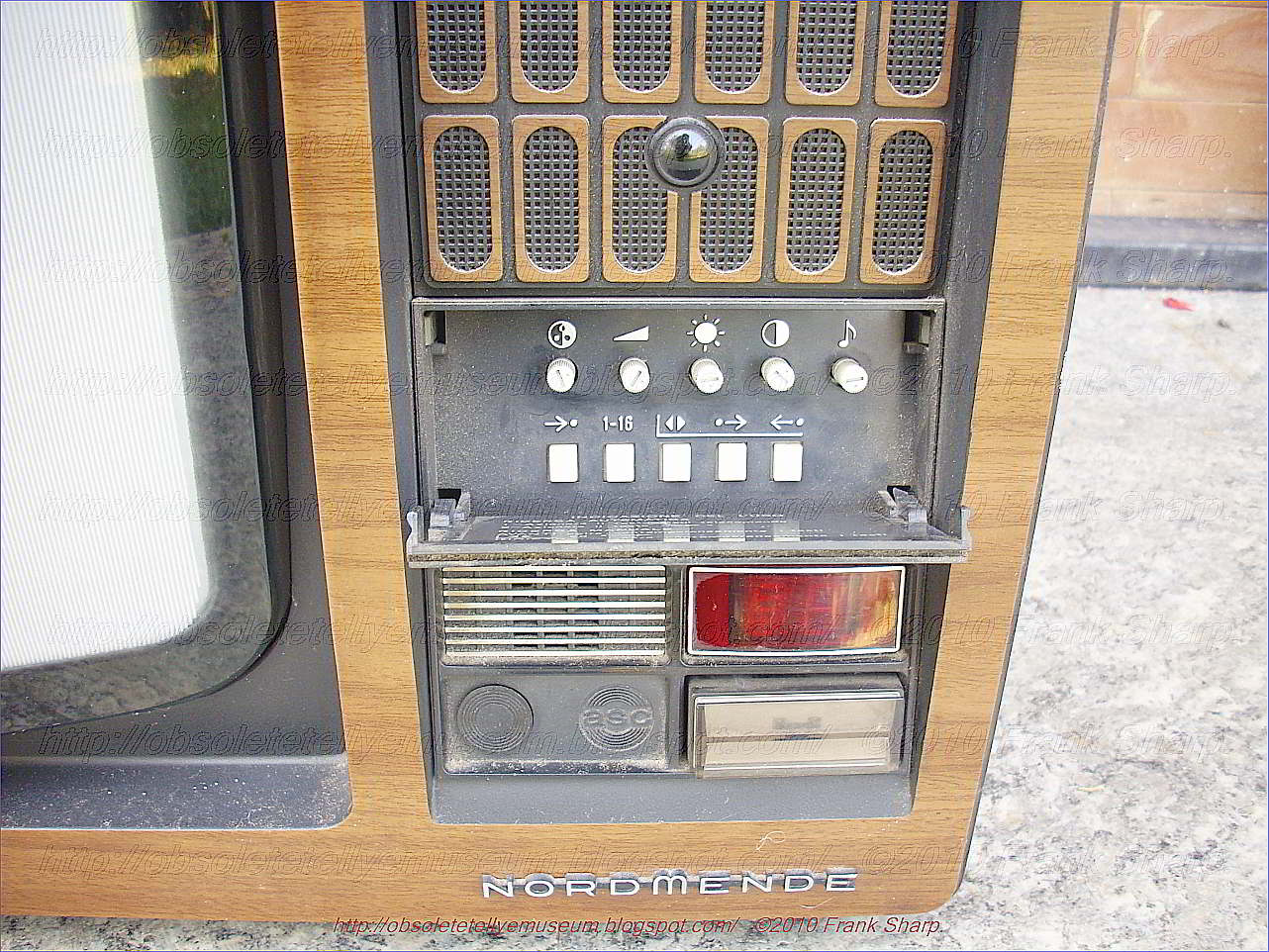
The set has even front led lamps to show the remote controls during calling via US remote and a front display showing program numbers.
IT also has a photo cell to control the ambient light and adjust contrast accordingly but different from others brands because it has an incorporated lamp to provide more accurate tracking.
On the front panel Right upside near the power switch there is a ambient light sensor which drives, in opportune, way the contrast tracking of the picture as a function of the light in the room were the tellye is running; more particularly to a control system for maintaining proper balance between room lighting conditions and the level of picture tube excitation in a color television receiver. More especially the present invention functions to increase contrast, intensity and chroma signal strength when the room lighting level increases to diminish these parameters when the level of room lighting decreases.
Conventional television receivers, of course, have manually operable controls by means of which a viewer may set the level of contrast, intensity, and chroma signal strength to what he feels to be an optimum level for given room lighting conditions. Under changed room lighting conditions, the viewer will obtain the optimum viewing situation by changing these manual controls to a new preferred level.
The set here shown has the well known "child lock" feature on the mains switch like almost all NORDMENDE color set from that era of time, see pictures. A power supply control apparatus for a television receiver is useful in preventing a child from watching a television for excessive lengths of time. There has been already proposed such an apparatus in which a key is used to mechanically lock the power switch of the television receiver. The power switch locking device of the invention cooperates with a function switch or key specified in the electrical appliance to control the on/off function of the power switch.
This here shown is a heavy used set for almost 25 Years by the original owner combined with all day permanent power on.
All transistor color VHF/UHF TV receiver powered from AC net 220V/50Hz.Woodencabinet.
(To see the Internal Chassis Just click on Older Post Button on bottom page, that's simple !)
Nordmende was a manufacturer of entertainment electronics based in Bremen, Germany.
The original company, Radio H. Mende Co, was founded in 1923 by Otto Hermann Mende
(1885-1940) in Dresden. Following the destruction of the plant during the bombing raids in 1945, Martin Mende (the founder's son) created a new company in Bremen in 1947, in a former Focke-Wulf plant, under the name North German Mende Broadcast GmbH.
The name was subsequently changed to Nordmende: subsequently the
company became one of the prominent German manufacturers of radios,
televisions, tape recorders and record players in the 1950s and 1960s.
In
the 1970s, Nordmende televisions were renowned for their innovative
chassis, and for the rigorous testing and quality control of their
finished products. Both created high costs, however, which soon proved a
competitive disadvantage when the price of colour televisions began to plunge.
In 1969, Mende's sons took over the company, and in 1977 a majority shareholding was sold to the French Thomson Brandt company and the chassis remains the original NordMende until CHASSIS F9. The
following year, the family sold their remaining shares to Thomson.
In the 1980s, the factories in Bremen were closed, Nordmende becoming
purely a Thomson trademark (Starting from chassis F10 F11 they're all THOMSON).
In the 1990s, the name Nordmende was used with decreasing frequency, and it eventually disappeared in favour of the Thomson name. In 2005 Videocon Group acquired all cathode ray tube activities from Thomson. This led to the creation of VDC Technologies, which manufactures TV sets using the Nordmende brand under licence from Thomson.
The Nordmende brand name was relaunched in Ireland in September 2008 by the KAL Group. Although
 Nordmende
was well known for its televisions throughout Ireland during the
1970s and 1980s, the company bought the rights to the name and
launched a range of white goods including fridges, freezers, washing machines, and dishwashers, alongside a revamped range of flat-screen TVs and stereos.
Nordmende
was well known for its televisions throughout Ireland during the
1970s and 1980s, the company bought the rights to the name and
launched a range of white goods including fridges, freezers, washing machines, and dishwashers, alongside a revamped range of flat-screen TVs and stereos.
NORDMENDE HISTORY IN GERMAN:
Die Vorkriegsgeschichte findet sich unter Mende. Nach dem T
otalverlust in
Dresden gründet Martin Mende (30.12.1898-1982) unter Mitwirkung von
Hermann Weber am 26. August 1947 in Bremen-Hemelingen die
Norddeutsche Mende-Rundfunk GmbH.Die ersten Gehäuse liefert ein Tischler in Achim gegen Kompensation von fünf Gehäusen zu einem Rundfunkgerät. Der frühere Mende-Konstrukteur, Obering. Heer zeichnet wieder für die Geräte verantwortlich [FT49??].
Ab 27. Juli 1948 liefert die neue, zuerst 18 und bald 60 Personen umfassende Firma auf Grund von Währungsreform, Krediten und Zulieferverträgen die neue Radioproduktion.
Das Regime in Ostdeutschland lässt den Namen Mende nicht zu, so dass Martin Mende mit grafischen Konstruktionen im Zusammenhang mit «Nord» an seinen Vorkriegserfolg anschliesst.
Die Hallen der ehemaligen Focke-Wulf AG beim Bahnhof Seebaldsbrück dienen als Werkstätten. 1950 beschäftigt das Unternehmen 700, 1959 schon 3500 und im Zenit 6300 Personen.
1950 beginnt die Firma mit UKW-, 1953 mit Fernseh- und 1954 mit Mess- und Prüfgeräten. Gegen Ende der 50er Jahre heisst die Firma Norddeutsche Mende Rundfunk KG [RP7901].
Nachdem sich Nordmende bislang nicht mit Magnettongeräten befasst hat, bringt das Werk 1958 das erste deutsche Heim-Tonbandgerät mit drei Motoren auf den Markt. Allerdings dominieren auf diesem Sektor eindeutig andere Firmen wie AEG/Telefunken und Grundig. Von Nordmende kommen jeweils nur ein bis zwei Geräte (1960 keines) in die Kataloge. Dafür hat die Firma Erfolg mit einem anderen Neueinstieg:
1958 stellt Nordmende mit «Mambo» ihr erstes Reisegerät vor - aber nicht «das erste deutsche, serienmässig hergestellte und volltransistorisierte Koffergerät», wie man aus einer Quelle nachlesen kann. Danach wird Nordmende in Deutschland auf dem Sektor Reisegeräte besonders stark, obwohl sie keine Röhren-Koffer baute. Immerhin kosten die in «Mambo» verwendeten 8 Halbleiter dann im Einzelhandel DM 98.70, während für die vier D-Röhren der 90er-Serie - auch zum Katalogpreis - etwa DM 35.- auszugeben wären. Preis des ganzen Gerätes: DM 189.- plus zwei Flachbatterien von 4,5 V.
Bis 1969 gibt es ca. 92 Modelle der tragbaren Radios (Koffer- bzw. «Handradios», d.h. «Hand held radios»). Beispielsweise finden sich im Katalog 1961/62 [448] je 11 Tischradios und Radiomöbel sowie 8 Modelle von Reiseradios. 17 verschiedene Fernsehmodelle zeigen dagegen, wo in jener Zeit der Erfolg zu holen war.
Gemäss [FT7901] liegt Nordmende während kurzer Zeit mit der sogenannten «Tippomatik-Bedienung» sogar technisch vorne. Siehe auch Philips etc.
Auch Konzertschränke scheinen Ende der 50er bis Anfang 60er Jahre eine tragende Säule für Nordmende zu sein. Dabei verwendet die Firma immer wieder gleiche Namen wie «Cabinet», «Caruso», «Casino», «Cosima» sowie «Arabella» und «Isobella» mit wechselnden Zusatz-Nummern oder den Zusatz «Stereo», z.B. in den Jahren 1959 und 1960/61.
Im März 1967 nimmt das Werk die Produktion von Farbfernsehgeräten auf. Zum Firmenjubiläum erscheint eine Gerätereihe mit der Bezeichnung 'Goldene 20'. 1969 übernehmen die Mende-Söhne Karl und Hermann die Geschäftsführung.
1977 führt der verschärfte Wettbewerb zum Verkauf der Mehrheit an den französischen Konzern Thomson-Brandt; die Familie Mende zieht sich anschliessend ganz aus dem Unternehmen zurück. Martin Mende stirbt 1982.

Weblinks:
Tote Marke NORDMENDE – Verblasster Stolz. Artikel im Manager-Magazin
Ein neues Programm. Artikel in der Zeit
Fernseher: Inder produzieren neue Nordmende. Artikel bei itespresso.de
Videocon produziert Plasmaschirme für Nordmende. Artikel im pressetext.de
Einzelnachweise
Spectra Color Studio und Spectra SK2 Color de Luxe Studio auf radiomuseum.orgMarke Nordmende mit Digital- und Internetradios zurück, teltarif.de, Artikel vom 2. September 2017.
Company profile. Phillar, archiviert vom Original am 6. März 2008; abgerufen am 26. April 2013 (englisch).
Broschüre – Sprachmanager24. Abgerufen am 5. Januar 2015.
No comments:
Post a Comment
The most important thing to remember about the Comment Rules is this:
The determination of whether any comment is in compliance is at the sole discretion of this blog’s owner.
Comments on this blog may be blocked or deleted at any time.
Fair people are getting fair reply. Spam and useless crap and filthy comments / scrapers / observations goes all directly to My Private HELL without even appearing in public !!!
The fact that a comment is permitted in no way constitutes an endorsement of any view expressed, fact alleged, or link provided in that comment by the administrator of this site.
This means that there may be a delay between the submission and the eventual appearance of your comment.
Requiring blog comments to obey well-defined rules does not infringe on the free speech of commenters.
Resisting the tide of post-modernity may be difficult, but I will attempt it anyway.
Your choice.........Live or DIE.
That indeed is where your liberty lies.
Note: Only a member of this blog may post a comment.